

Page 1
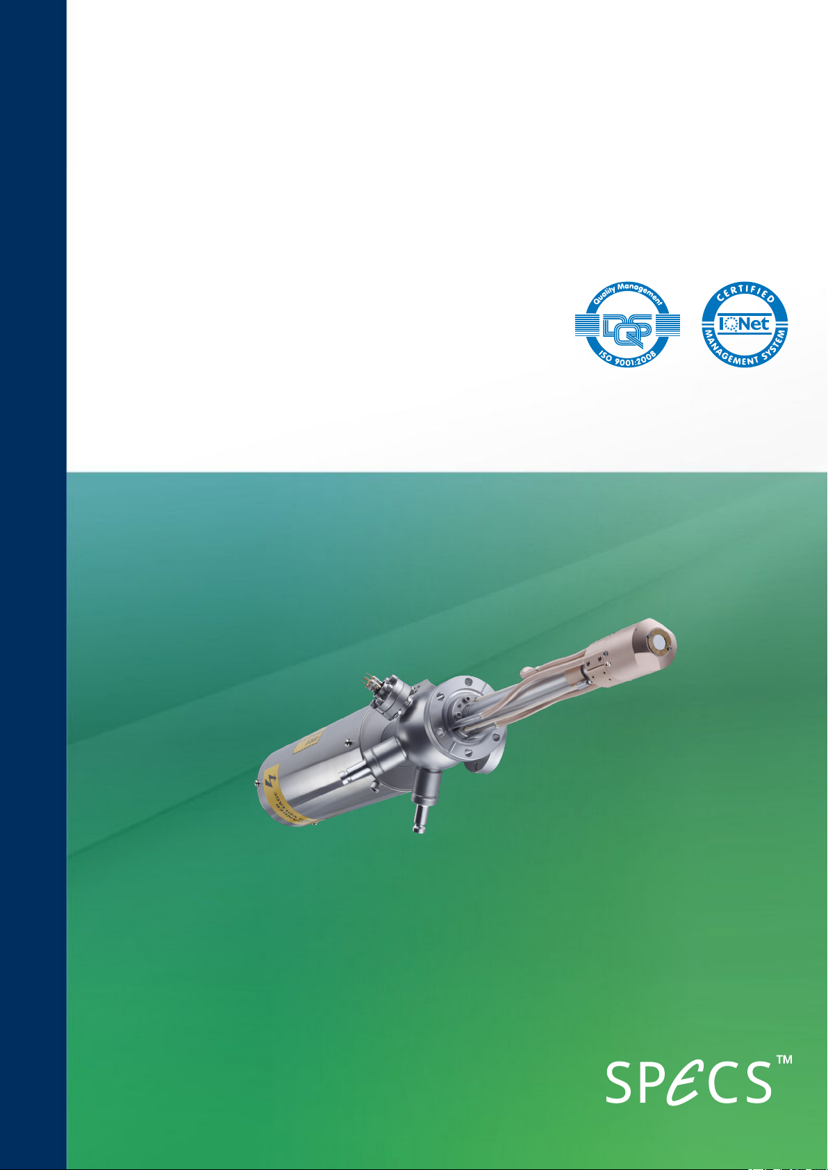
XR 50
XR 50 NAP
X-Ray Source
User Manual V3.1 | May 02, 2016
Page 2

SPECS Surface Nano Analysis GmbH
Voltastrasse 5
13355 Berlin
Germany
Tel:
Fax:
Email:
Web:
+49 30 46 78 24-0
+49 30 46 42 08-3
http://www.specs.com
SPECSUser Manual
XR 50—X-Ray Source, Version 3.1
May 02, 2016
SPECS order number reference: 2100002828
©2016. All rights reserved. No part of this manual may be reproduced without the prior per-
mission of SPECS GmbH. Other product and company names mentioned in this document may
be the trademarks or registered trademarks of their respective owners and are used for iden-
tification purposes only.
Page 3
Table of Contents
List of Figures
Chapter 1 – Introduction
1.1 About this Manual
1.2 Further Sources of Information
1.3 Safety
1.4 Environmental Operating Conditions
Chapter 2 – Installation
2.1 Unpacking
2.2 Vacuum Installation
2.2.1 Vacuum Conditions
2.2.2 Differential Pumping
2.2.3 Z-Drive (Optional)
2.3 Bakeout
2.4 Water Cooling
2.4.1 Fitting the Protection Cap
2.4.2 Head Cooling Circuit
2.5 Connecting Electrical Supplies
2.5.1 Electrical Connections
2.5.2 Interlocks
2.6 Anode and Filament Conditioning
iii
1
1
2
3
5
5
5
6
7
7
8
8
9
10
10
11
12
Chapter 3 – Operation
3.1 Switching On
3.2 Adjusting Settings During Operation
3.3 Switching Off the Source
Chapter 4 – Troubleshooting
4.1 High-Voltage Sparks
4.2 Basic Electrical Checks
4.3 Unstable Operation at Low Power
4.4 Cross Talk between Anodes
Chapter 5 – Maintenance
5.1 X-Ray Source Check
5.2 Replacing the Anode
5.3 Replacing the Cathode
5.4 Replacing the Water Inlet
5.5 Replacing the Aluminium Window
5.6 Anode Storage
15
17
18
19
20
21
21
25
26
27
29
30
31
XR 50 V3.1 | May 02, 2016
Page 4
iv
Chapter 6 – Source Overview
6.1 Anode
6.1.1 Operating Limits
6.1.2 Excitation Energies
6.1.3 Cross-Talk
6.1.4 Water Circulation
6.2 Specifications
6.2.1 Anode
6.2.2 Cathode
6.2.3 Operation Range
6.2.4 Setup
34
34
35
36
37
38
38
38
38
39
Chapter 7 – Principles of Operation
7.1 Generation of X-Rays
7.2 Output Intensity
7.3 Voltages and Currents
7.3.1 Anode Voltage and Current
7.3.2 Emission Current
7.3.3 Filament Current and Voltage
7.3.4 Water Current
7.4 Magnetic Fields
41
41
42
42
42
42
43
43
Chapter A – XR 50 NAP
A.1 Construction
A.2 Operation
A.3 Replacing the Window
Index
45
46
47
XR 50 V3.1 | May 02, 2016
Page 5

List of Figures
v
Figure 1: Differential pumping flange
Figure 2: Bypass ring in the open position
Figure 3: Head cooling connections
Figure 4: Electrical and water connections
Figure 5: The source startup menu
Figure 6: Conditioning the filament
Figure 7: Front panel of the UXC 1000
Figure 8: Entering the presets menu
Figure 9:Selecting a preset
Figure 10: Activating a preset
Figure 11: Operating menu
Figure 12: Pins on filament feedthrough
Figure 13: Checking isolation of sections in the source
Figure 14: Correct orientation of anode
Figure 15: Distance of anode to cross-talk suppression ring
Figure 16: Setting the cap position
Figure 17:Cathode (filament) assembly
Figure 18: Anode water cooling flange and tube
Figure 19: Source overview
Figure 20: Limits menu for setting maximum anode power
Figure 21: Cross-talk suppression
Figure 22: Cross-talk in the XR 50
Figure 23: Anode cooling circuit
Figure 24: Heat cooling circuit
Figure 25: Principle of operation
Figure 26: The voltages and currents involved in the X-ray source
Figure 27: Construction of the XR 50 HPand XR50
6
7
10
11
12
13
15
16
16
17
17
21
21
22
22
23
27
30
33
35
36
37
37
38
41
42
46
XR 50 V3.1 | May 02, 2016
Page 6
vi
This page intentionally left
XR 50 V3.1 | May 02, 2016
Page 7
Chapter 1 – Introduction
Welcome to the user manual for the SPECS XR 50. This instrument is an X-ray source with a
twin anode that is optimized for XPSmeasurements.
This chapter explains briefly how to use the manual and points you to further sources of inform-
ation.
Most importantly, it contains safety notices that you should read before operating the equip-
ment.
1.1 About th is Man u al
This manual is intended for users of the XR 50 X-Ray Source. It is divided into the following
chapters:
Chapter 2 contains instructions on how to install the equipment so that it is ready to be
switched on.
Chapter 3 guides you through the procedures for using the XR 50.
Chapter 4 has some troubleshooting advice.
Chapter 5 describes maintenance procedures that you can perform on the source.
Chapter 6 is an overview of the construction of the source, including specifications.
Chapter 7 offers some background information about the principle of operation.
1
Further information is also contained in the appendix:
Appendix A covers the XR 50 NAP, a high-pressure variant of the XR 50.
1.2 Fu r th er Sou rces of Informati on
This manual describes the UXC 1000 and its use with the XR 50. For safe and reliable operation,
you should also refer to the following manuals:
UXC 1000 manual for a full description of the power supply, including all available options
in the menu system, the pin assignments on the rear panel connectors and a complete list
of error messages for troubleshooting.
CCX 70 manual for information about the water cooling system, including water require-
ments and cleaning procedures.
For further advice and assistance, please contact SPECSsupport:
Tel: +49 30 46 78 24-0
email: [email protected]
XR 50 V3.1 | May 02, 2016
Page 8
2
If you need to return this SPECS product for repair, service or upgrade, please first contact
SPECS support. We will provide you with an RMA as well as details for correct packaging and
shipment of the instrument. This will ensure safe transportation and speedy processing.
1.3 Safety
Before any electrical or electronic operations please consult "SPECS Safety Instructions" and
follow them. Some tests which may have to be carried out are dangerous.
Pay special attention to the safety notices below as well as those that appear in the procedures
described in this manual and the other operating manuals listed in "Further Sources of Inform-
ation" on page 1.
Electrica l safety
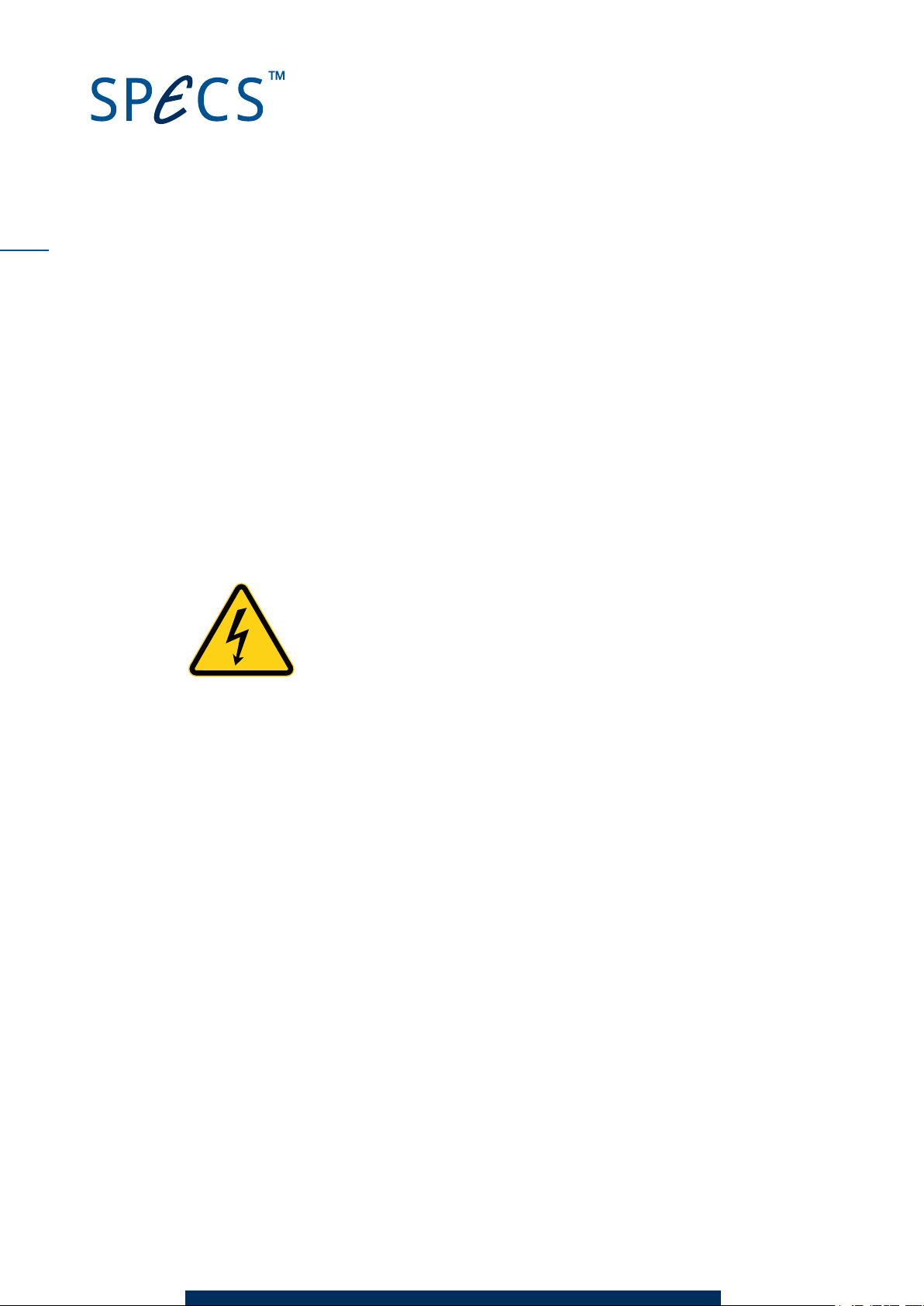
Danger—High Voltages Present!
Beware! Hazardous voltages are present. Lethal high voltages up to 15 kV
are applied to the X-ray source. Only trained, qualified personnel are allowed
to carry out the installation, adjustment and repair procedures described in
this manual. Make measurements only with specially insulated tools rated
for voltages higher than 20 kV!
The XR 50 module uses high voltages up to 15 kV! It is important to comply with the following
safety directives:
Use only original cables, connectors, and flexible conduits supplied by SPECS. Make sure
that all cables and water lines are without physical or electrical defects.
Make sure the power supply is grounded with a proper HF cable.
Only operate the XR 50 with the protection cap in place. Do not modify the protection cap in
any way.
Do not operate the X-ray source unless your system pressure is below 10–6mbar.
Do not override or defeat the interlocks in any way.
Never operate the power supplies with the case open.
Connect the XR 50 only when the power supplies are turned off.
After switching off the power units, wait a minimum of 3 minutes before making dis-
connections or opening power supplies or the X-ray source protection cover.
In the event of a water leak at the source, completely dry of the module, the protection
cover, the conduit and the cables before attempting to operate the source.
Operating the XR 50 with equipment other than that delivered by SPECS may void your war-
ranty. Contact SPECS for advice.
XR 50 V3.1 | May 02, 2016
Page 9
Rad i a tion saf ety
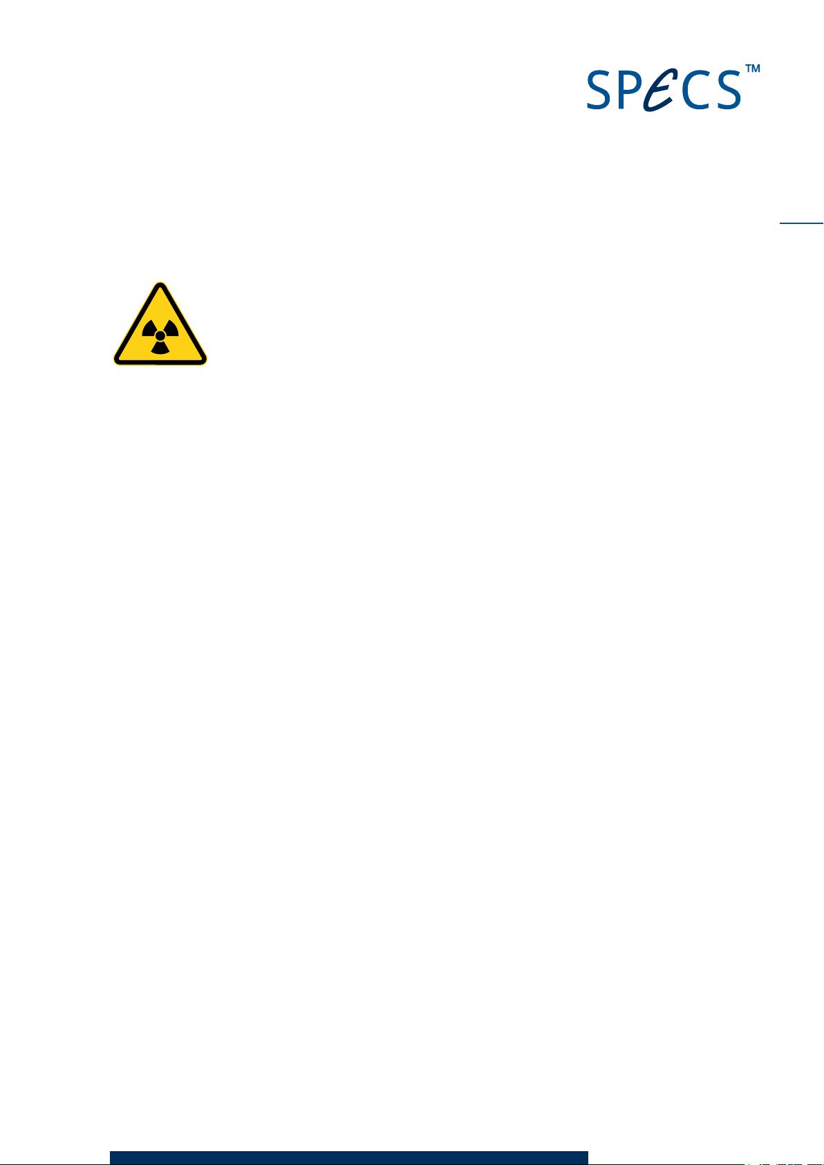
Warning—Ionizing!
All federal, state, company and/or department internal regulations, restric-
tions, codes, and rules for protection against radiation sources have to be
observed during installation and operation of the X-ray source at your site!
Consult your radiation control officer in case of any doubt. The user is
responsible for the correct labeling of the source and its power supplies, as
well as providing safety instructions in the native language of the site!
With accelerating voltages of less than 20 kV, the local dose of 0.1 µSv/h will not be exceeded
within a distance of 0.1 m from the source. The source only runs in vacuum, i.e. access through
an open port is not possible. Normally, stainless steel chambers, components and viewports
with thickness greater than 1.5 mm thickness are not permeable.
In addition to the regulations, restrictions, codes, and rules for protection against radiation
which have to be observed by the law at the operational site of the XR 50, SPECS recommends
the following:
All ports of the chamber should be closed by blank flanges or compact UHV components
made of stainless steel or leaded glass.
If the chamber is fitted with large components made of other materials (e.g. glass), consult
your radiation control officer.
Pregnant women should inform their supervisor or safety inspector of their pregnancy for
reasons of health, safety, and legal liability, and in the event that additional safety meas-
ures are required.
3
1.4 Environmental Operating Conditions
The equipment must be installed in a dry, dust free laboratory. The following conditions are
required for operation.
Temperature (normal system operation):
absolute limit range: 15–30 °C (60–85 °F)
recommended range: 20–25 °C (68–77 °F)
Relative humidity:
absolute limit values: 40–80%
recommended range: 50–60%
There must be no condensed water on the equipment.
Atmospheric pressure:
XR 50 V3.1 | May 02, 2016
Page 10
4
800–1200 mbar
Air conditioning is advisable in order to ensure the ambient requirements, especially for dis-
sipating heat produced by the equipment.
XR 50 V3.1 | May 02, 2016
Page 11
Chapter 2 – Installation
Installation of the XR 50 involves the following steps:
Unpacking and checking the source.
Fitting the source onto the vacuum chamber.
Baking out.
Connecting the water cooling supplies.
Connecting the power supplies.
Conditioning the source.
After performing these procedures, the source is ready for use.
2.1 Unpacking
The XR 50 is delivered with the UXC 1000 power supply, the CCX 70 water cooling controller
and connection cables and hoses. A packing list supplied with the delivery details all items sup-
plied. Please check this list carefully and save it for future reference.
When unpacking, carefully inspect all parts for signs of transport damage. If any parts are
broken or damaged, please contact SPECS before continuing.
5
2.2 Vac uum Installa tion
The XR 50 is suitable for UHV chambers and is mounted on a DN40CF flange.
When installing the XR 50, check the following:
The inner diameter of the flange where the XR 50 will be attached. Estimate the dimen-
sions of welding seams and mu-metal ports!
The gasket is large enough for the XR 50. The minimum inside diameter is 38mm—a gas-
ket with an inside diameter of 35 mm is too small.
There are no major restrictions on the orientation of the XR 50; however, if it is mounted on a
spherical chamber with the energy analyzer on top, the 4-pin feedthrough should be aligned
horizontally.
The following sections describe the necessary vacuum conditions and options for differential
pumping, as well as how to fit an optional Z-drive.
2.2.1 Vacuum Conditio ns
The upper operating limit of the XR 50 is 1 × 10⁻⁵mbar. In order to prevent contamination and
extend the lifetime of the source, you should use the source in the 10–6mbar range or better.
XR 50 V3.1 | May 02, 2016
Page 12
6
2.2.2 Differential Pumping
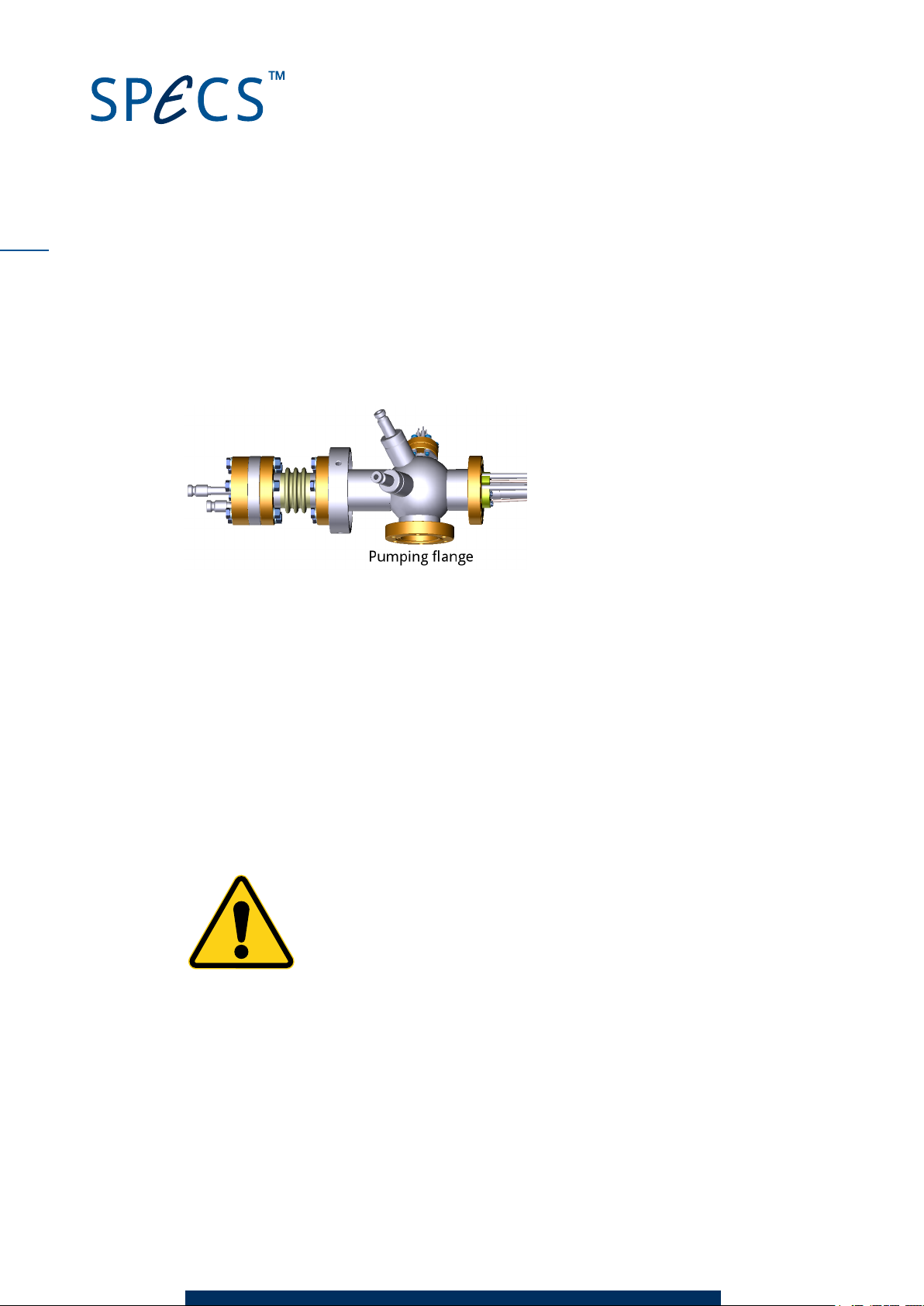
You can differentially pump the XR 50. There are several advantages to this:
Better vacuum conditions in the anode volume, especially during bakeout.
Less damage to the source if harmful or aggressive gases are in use.
Reduction of aging effects of the anode and the Al window.
Figure 1: Differential pumping flange
The simplest solution for a bypass is the installation of a flexible bellows between the XR 50
bypass flange and a suitable flange on the vacuum chamber. Depending on your configuration,
you may also want to fit a valve to the bypass line in order to be able to isolate the differential
pumping section from the pumping chamber.
More elaborate bypass systems include either ion getter pumps or turbomolecular pumps,
combined with a valve for simultaneous venting with the main chamber.
When installing the XR 50 with differential pumping, orient the source so that the water con-
nectors face upward.
Caution!
The bypass line must be vented simultaneously together with the main cham-
ber to avoid damaging the Al-window.
Set the bypass ring shutter on the X-ray source main frame as follows:
Open—if no differential pumping system is installed.
Closed—if a differential pumping system is installed.
XR 50 V3.1 | May 02, 2016
Page 13
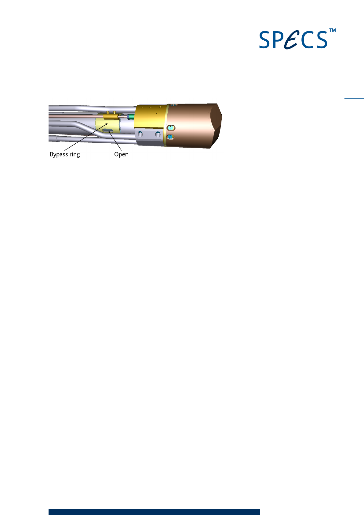
Figure 2: Bypass ring in the open position
2.2.3 Z-Drive ( Optional)
The XR 50 can be supplied with an optional Z-drive so that the source can be retracted from its
working position. This protects the head of the source (and its aluminium window) from dam-
age, e.g. from sputtering, or prevents the source from obstructing other equipment.
Note
The cooling system of the XR 50 is efficient—there is generally no need to retract the XR 50 in
order to reduce thermal strain on other equipment.
The Z-drive is available in 50 mm and 100 mm versions.
In order to prevent collisions between the HV shield and the Z-drive, a spacer is provided. This
is a 40 mm tube with a DN40CF flange at each end, one flange being rotatable. You should
attach the items to the chamber in the following order:
Z-drive
Spacer
Source
7
2.3 Bakeou t
The XR 50 can be baked up to 180 °C. Remember to observe the maximum bakeout tem-
perature for other equipment on your system. Do not use heating tapes or jackets for the
bakeout—these can lead to hotspots which can damage the source and cause uneven baking
conditions which may lead to pressure bursts and arcing during operation.
Before baking out, observe the following points:
Unplug the grounding cables.
Remove the protection cap and supporting frame.
Remove all cables and water connections from the XR 50.
Blow any water out of the source using compressed air.
XR 50 V3.1 | May 02, 2016
Page 14
8
Danger—High Voltages Present!
It will take 3 minutes before all high voltages are absent in the system. Wait
at least 3 minutes before disconnecting any cables from the power supply or
the X-ray source.
2.4 Wa ter Cooling
Adequate water cooling is vital for the operation of the XR 50. The electrical connections dia-
gram in Figure 4 on page 11 also shows the necessary water connections. The following sec-
tions provide additional information about the water circuits as well as the basic requirements
for the cooling water.
SPECS supports only the use of water as the cooling agent for the XR 50.
Caution!
The quality of the water supply is critical to the stable and reliable operation
of the XR 50. Please refer to the CCX 70 manual for requirements of the cool-
ing water.
2.4.1 Fitting the Protection Cap
During operation, the top flange of the XR 50 is at high voltage. For safety reasons, a protection
cap prevents access to this flange. A safety interlock switch mounted on the side of the cap is
closed when the cap is correctly in position. The high voltage can only be activated when this
switch is closed.
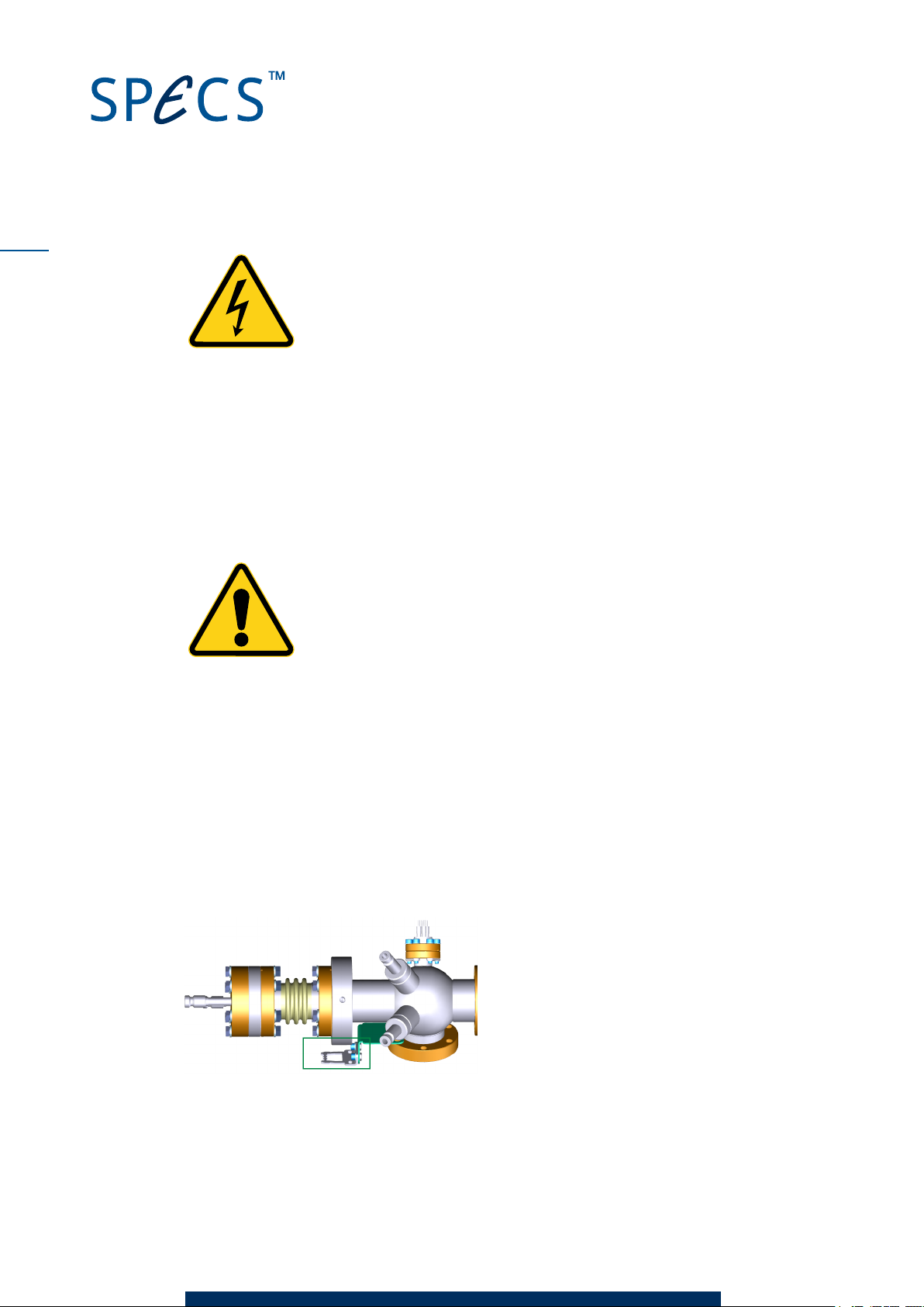
The picture below shows the source head before fitting the protection cap. Note the position of
the safety switch contact (marked with a green box) . You need to use this for orientation of the
protection cap.
To fit the protection cap:
1. Fit the support frame over the source flange and tighten the three grub screws to fix it into
place. This supports the weight of the conduit while connecting the water hoses.
XR 50 V3.1 | May 02, 2016
Page 15

2. Fit the water hoses onto the cooling pipes, making sure to observe the correct flow dir-
ection. The hoses and pipes are labeled with arrows. The center (longer) pipe is for water
flowing into the source.
Note
The high voltage connections are also made when you fit the hoses.
3. Slide the protection cap over the frame so that the contact fits into the safety switch.
4. Secure the protection cap with the three screws around the side of the cap.
9
Removing the protection cap is the reverse of the above. Note the following points:
When pulling the cap away from the head, take care not to strain the cable for the safety
switch interlock.
Always disconnect the water connectors before removing the support frame. Without the
frame, the weight of the conduit can damage the water hoses.
2.4.2 Head Cooling Circuit
The XR 50 has a second cooling circuit to cool the area around the filament and anode. The
body of the source remains cool, reducing radiative transfer of heat to other components (or
the sample).
Figure 3 shows the location of the head cooling connectors. The direction of flow through this
circuit is not important.
XR 50 V3.1 | May 02, 2016
Page 16

10
Figure 3: Head cooling connections
2.5 Connecting Electric a l Suppli e s
The following sections show the electrical connections for the XR 50 as well as a description of
the safety interlocks in the system.
For more information, please refer to the UXC 1000 manual.
2.5.1 Electrical Connections
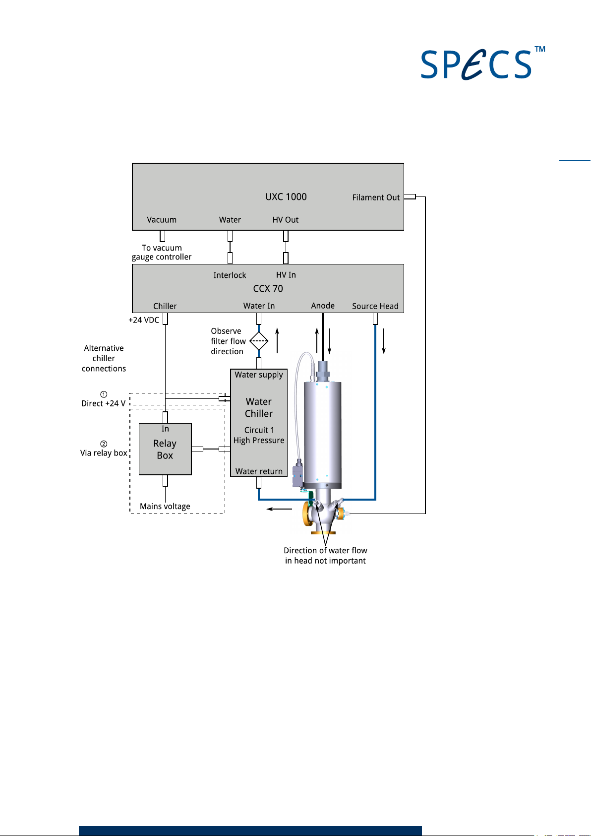
Figure 4 provides an overview of the electrical as well as the water connections for the XR 50.
If you have a water chiller supplied by SPECS, you can set it so that is it automatically switched
on and off by the CCX 70. There are two alternative methods for this connection (see Figure 4):
① Directly to the chiller, using a +24 V input on the chiller.
② Via a relay box, which switches the mains power supply to the chiller.
If you are not using a water chiller, e.g. tap water or another installed water supply, the con-
nection scheme is essentially the same, with your water supply in the place of the water chiller.
XR 50 V3.1 | May 02, 2016
Page 17
11
Figure 4: Electrical and water connections
2.5.2 Interlock s
The XR 50 is protected by a number of interlocks:
Water—sensors inside the CCX 70 monitor the water flow and temperature, sending the
signal to the UXC 1000. If these parameters fall outside the limits set in the UXC 1000,
source operation is stopped.
HV—the HVcable must be plugged into the back of the UXC 1000 before the high voltage
can be activated.
Protection cap—there is a microswitch on the protection cap that is closed when the cap is
correctly fitted. The high voltage can only be activated when this switch is closed.
XR 50 V3.1 | May 02, 2016
Page 18
12
Vacuum—the UXC 1000 can be connected to a vacuum gauge measurement controller.
When the pressure interlock trips, the high voltage and filament are switched off. A
bridging connector is provided in case you do not need to use this interlock. Some form of
vacuum interlock is however recommended in order to protect the source from high pres-
sures.
If the XR 50 is correctly connected and the conditions described in this chapter are met, these
interlocks are safe and the XR 50 can be operated.
Caution!
Do not attempt to defeat the interlocks. Death, serious injury or severe dam-
age to the source can result if the interlocks are overridden.
2.6 Anode and Fi lamen t Conditioning
After baking out the XR 50, there will still be adsorbates on the working surfaces of the source.
These will cause outgassing and HV discharges when you try to operate the source. The con-
ditioning procedure removes these adsorbates by slowly ramping the source parameters up to
their operating values. By the end of the conditioning, the source should be ready for normal
use.
To condition the filament and anode:
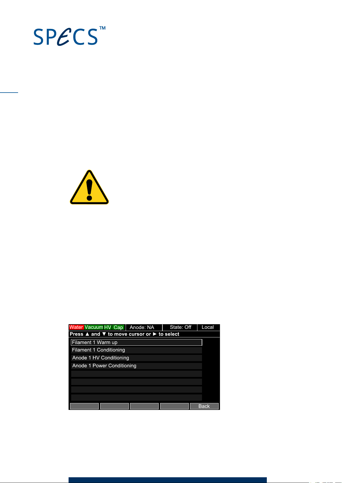
1. Switch on the UXC 1000. A splash screen will appear while the unit starts up. After a short
time. the main menu will appear. A rectangular cursor surrounds the item Anode 1 startup
procedures.
2. Press ► to select the item. The Anode 1 startup procedures menu will appear.
Figure 5: The source startup menu
XR 50 V3.1 | May 02, 2016
Page 19
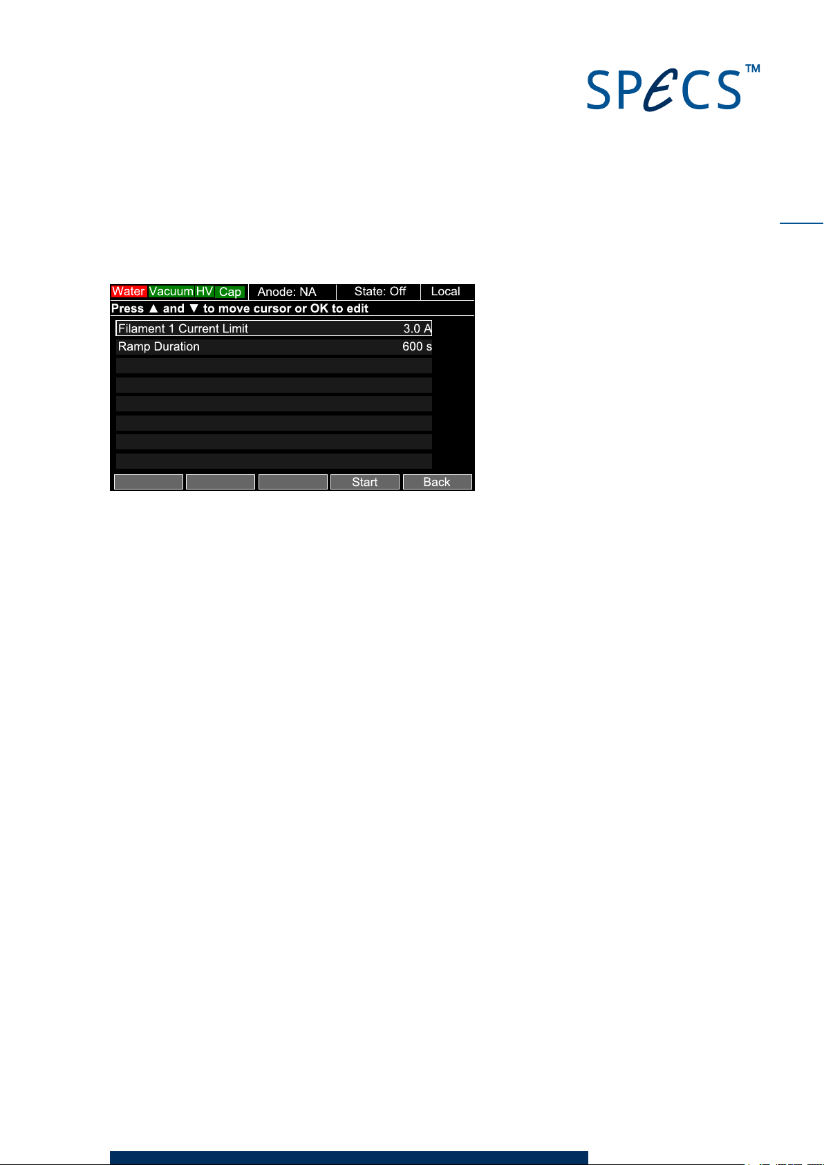
3. Press ▼ once to move the cursor down one space to Filament 1 Conditioning and then
press ► to select.
Figure 6: Conditioning the filament
13
4. Press the
Start
softkey (bottom right key below the display). The UXC 1000 will ramp the fil-
ament up to the current limit shown in the menu over the warmramp time. When it has fin-
ished, a notification will appear.
5. PressOK. The screen will return to the Anode 1 startup procedures menu. Note that Anode
1 is now indicated in the top information bar.
6. Press ▼ to select Anode 1 HV Conditioning and then press ►.
7. Press the
Start
softkey. The UXC 1000 will ramp the HV up to 15 kV over the ramp time.
When it has finished, a notification will appear.
8. PressOK. The screen will return to the Anode 1 startup procedures menu.
Note
Since the two anodes are electrically connected, this procedure also conditions anode 2.
9. Select
10. Press the
Anode 1 Power Conditioning
Start
softkey. The UXC 1000 will ramp the filament and anode until the preset
and then press ►.
maximum power is reached. This completes the conditioning for Anode 1. When it has fin-
ished, a notification will appear.
11. PressOK. The UXC 1000 will return to the main menu.
12. Select
Anode 2 Startup Procedures
and press ► to enter the Anode 2 startup procedures
menu.
13. Condition the filament and power for anode 2 in the same way as for anode 1.
Note
As noted above, the HV conditioning applies to both anodes. There is therefore no need to per-
form the Anode 2 HVconditioning if you have already done this for anode 1.
XR 50 V3.1 | May 02, 2016
Page 20
14
This page intentionally left
XR 50 V3.1 | May 02, 2016
Page 21
Chapter 3 – Operation
This chapter describes how to switch the XR 50 on and off and alter the operating parameters.
The UXC 1000 controls the source. It also activates the CCX 70 water cooling control box and
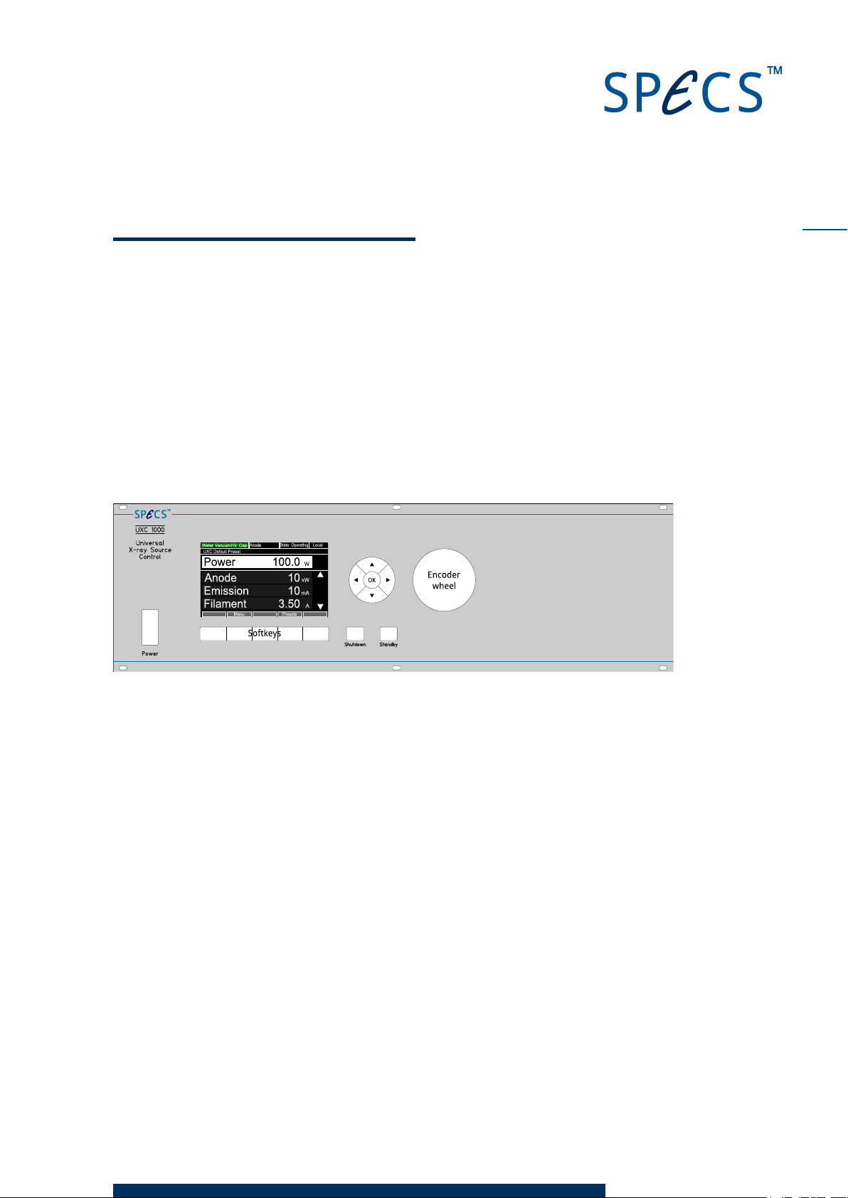
reads the status of the water cooling. Figure 7 shows the front panel of the UXC 1000 with the
controls.
For a full description of the features available in the UXC 1000, including how to set your own
presets and adjust the instrument limits, please see the UXC 1000 manual.
15
Figure 7: Front panel of the UXC 1000
3.1 Switchi ng On
The UXC 1000 uses predefined sets of operating parameters called presets to start operation.
This allows you to conveniently start the source in a working configuration.
Default presets are included for the major operating modes. You can also save your own pre-
sets.
To operate the XR 50:
1. Switch on the UXC 1000. A splash screen will appear as the unit performs its start up check,
before the initial menu is displayed.
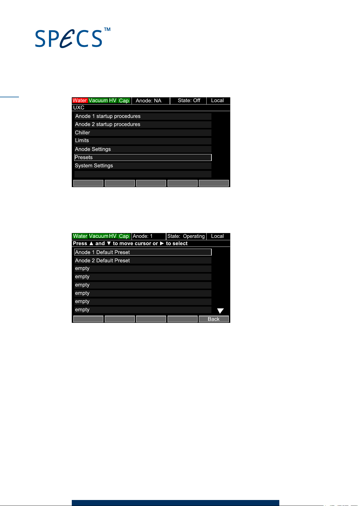
2. Press the ▼ key until the rectangular cursor surrounds
Presets
.
XR 50 V3.1 | May 02, 2016
Page 22
16
Figure 8: Entering the presets menu
3. Press ► to enter the
Preset
menu.
4. Use the ▲ and ▼ keys to select the preset you want to use.
Figure 9: Selecting a preset
5. Press the ► key to select the preset. A new screen appears which shows a list of para-
meters for the preset. The center column shows the current values of parameters; the
right column shows the saved preset parameters that you are going to use.
XR 50 V3.1 | May 02, 2016
Page 23
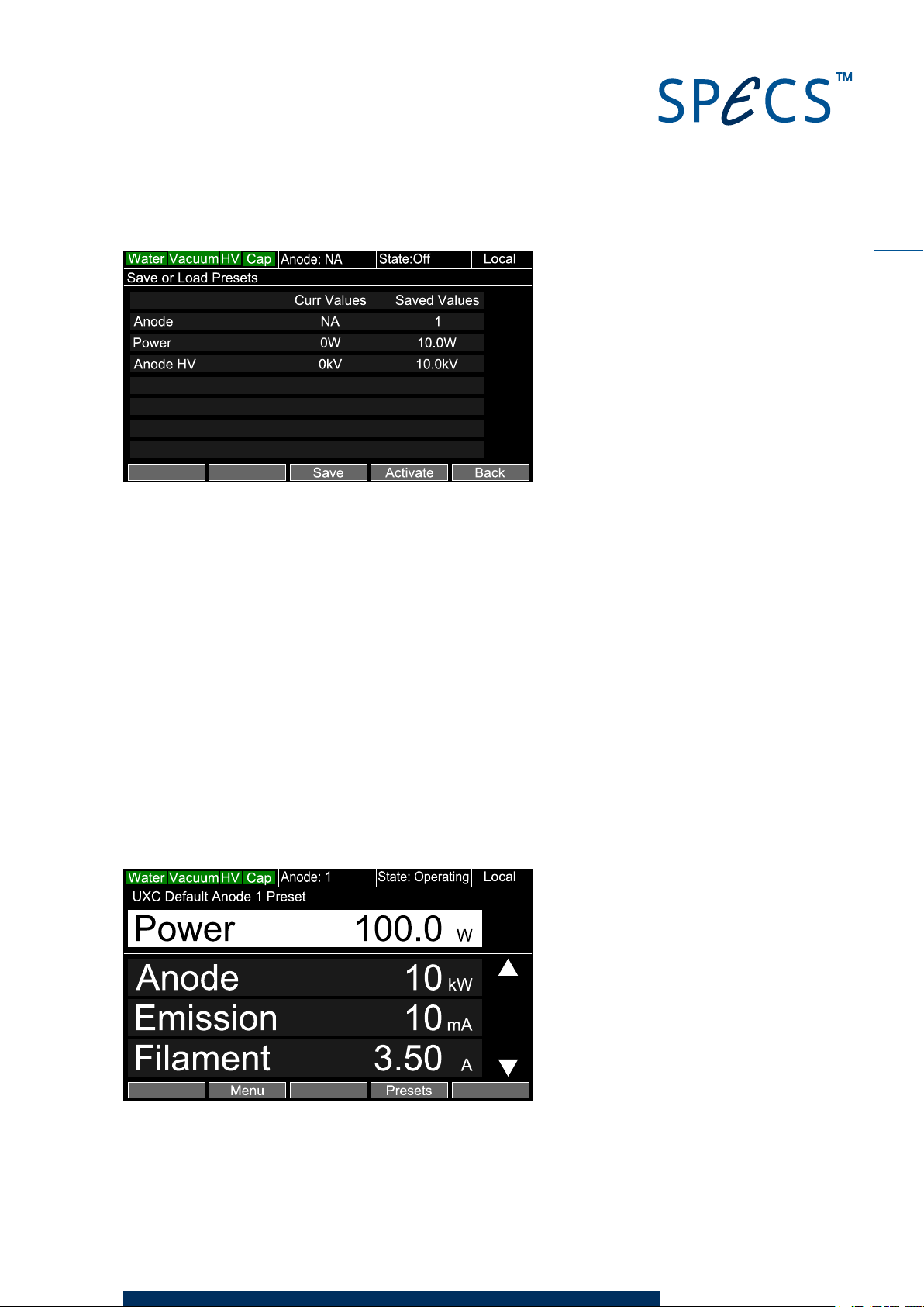
Figure 10: Activating a preset
17
6. Press the
Activate
softkey. This starts the following actions:
Current parameter values are replaced by those from the preset.
The water cooling will start, if it is not already running. A message will appear on the
screen as it starts.
The display switches to the operating screen.
The filament current ramps up to the standby current.
The high voltage is ramped up to the value in the preset.
The filament current is ramped up until the emission current enables the target power
(power = high voltage × emission current).
3.2 Adj u sting Settings Du ring Operati on
After starting the source, the operating menu is displayed. The top parameter shows the
power. This is the high voltage multiplied by the emission current. You can adjust the power
with the encoder wheel.
Figure 11: Operating menu
XR 50 V3.1 | May 02, 2016
Page 24
18
Three operating parameters are also shown in the display. You can view others by pressing the
▲ and ▼ keys to scroll the display. The complete list of parameters available in the display is:
Anode Voltage
Emission Current
Anode Current
Filament Voltage
Filament Current
There are the following active softkeys in the operating menu:
Menu—opens the main menu. This is the same as the initial menu but without the options
for conditioning the filament. You can view and change all settings from this menu.
Presets—opens the presets menu, allowing you to select a different preset.
3.3 Switchi ng Off the Source
To switch off the source:
Press the
filament to its standby value. The water cooling is still on in this case.
Press the
ply off.
Standby
Shutdown
button on the front panel. This switches the high voltage off and sets the
button. This switches the high voltage, the filament and the water sup-
XR 50 V3.1 | May 02, 2016
Page 25
Chapter 4 – Troubleshooting
This chapter discusses common problems that may occur during operation and offers some
methods for identifying the cause and solving the problem.
There are also some electrical checks that you can perform in order to locate problems, which
are also described here. If the source still does not work, you need to remove it from the cham-
ber and perform a visual inspection (anode, water cooling systems, etc). Please contact SPECS
support for further assistance.
The UXC 1000 displays an error message if there is a problem. These error messages may
help you to identify the problem. The UXC 1000 manual contains a full list of all error mes-
sages.
4.1 Hi gh -Voltage Sparks
The most common problem that occurs during the operation of the XR 50 is high-voltage spark-
ing. There are a number of reasons for this. If HV sparks occur, the power supply will switch off
the HV and go into standby mode. At the beginning of operation and after venting or after repla-
cing parts, some sparks may occur. Normally the occurrence of these HV sparks will decrease
over time.
19
Note
The risk of sparking is significantly lower when the high voltage is set to 12 kV rather than the
maximum of 15kV. The output intensity from the source is not much higher at 15 kV compared
to 12 kV.
Danger—High Voltages Present!
It will take 3 minutes before all high voltages are absent in the system. Wait
at least 3 minutes before disconnecting any cables from the power supply or
the X-ray source.
Warning!
If the frequency of sparks increases, it is absolutely necessary to determine
the cause. A high frequency of sparks indicates a problem with the source
that can lead to the evaporation of the anode material and even a cracked
anode.
XR 50 V3.1 | May 02, 2016
Page 26
20
The following checks may help you locate the cause of the problem. Contact SPECS (sup-
[email protected]) before performing potentially dangerous test procedures in your laboratory.
As a first step, check the following:
Water cooling. Make sure that the water temperature, flow and quality are all adequate.
See the CCX 70 manual for more information about the water requirements.
Anode power. Make sure it is within the limit set in "Operating Limits" on page 34.
Do the sp arks cau s e a p ressu re burs t?
Do the sparks affect the pressure inside the vacuum chamber? If so, check the following:
Operating pressure (10–6mbar or lower).
Water conductivity (see "Water Current" on page 43).
Aluminium window (see "Replacing the Aluminium Window" on page 30).
Anode condition (see "Replacing the Anode" on page 26)
Remove the source and check the following:
The distance between the anode and Al window rod. This rod suppresses the crosstalk
and the spacing is especially critical. It should be ~3.2 mm
Contamination or dust particles can cause HV sparks that result in the formation of
small craters.
Note
HV sparks outside the vacuum can affect the pressure reading—the response of the pressure
gauge controller to a HVdischarge may look like a pressure burst.
Are the co nnecti o ns and cables in tact?
Switch off the UXC 1000 and check the following:
The cables should all be intact, with no signs of wear or fraying. Remove the protection cap
and check the cable carefully.
Are there any traces of water, dirt or other contamination inside the protection cap? Check
also the flange, connectors and insulators.
Is the po wer s u p p ly wo rki n g correctly?
In the event of a problem with the power supply, the UXC 1000 will display an error message on
the display. Please refer to the UXC 1000 manual for a list of all error messages.
4.2 Basi c Electric al Checks
If the source is not working, you should first check that all parts are electrically intact. Use a
digital multimeter to perform the checks in this section in order to make sure there are no
short cuts and that the filament is not broken.
XR 50 V3.1 | May 02, 2016
Page 27

Check the resistance of the pins on the 4-pin filament feedthrough, as shown in Figure 12.
There should be a resistance of a few ohms between the pins.
Pin Assignment
A
Filament return
21
B
C
Filament 1
Shortcut to A
D Filament 2
Figure 12: Pins on filament feedthrough
There should be no connection between:
The anode and ground.
Any of the pins on the 4-pin feedthrough and ground.
The anode and any of the pins on the 4-pin feedthrough.
Figure 13: Checking isolation of sections in the source
4.3 Unstable Operation at Low Power
At very low powers (<5 W), the emission may be erratic. This is due to a limitation in the power
supply, which switches off the emission regulation below a certain threshold. When you try to
operate the source around this threshold, the operation can be unpredictable. As a result, the
XR 50 should be operated at powers above 5 W.
4.4 Cross Tal k between Anodes
As described in "Cross-Talk" on page 36, cross talk between the two anodes is very low. As
such, the amount of radiation coming from the other anode is almost negligible. If, however,
XR 50 V3.1 | May 02, 2016
Page 28
22
after changing the anode, you suddenly experience a substantial amount of cross talk, the new
anode is not in the correct position. There are two possible solutions for this problem, as
described below.
An o de is rotated
If the anode was inserted in the wrong orientation, both anodes will be visible to the cathode
and will therefore both emit X-rays. If you did not observe the correct orientation of the anode
when removing the old anode, you will need to remove the source from the chamber to check
the orientation. You can then easily correct the problem.
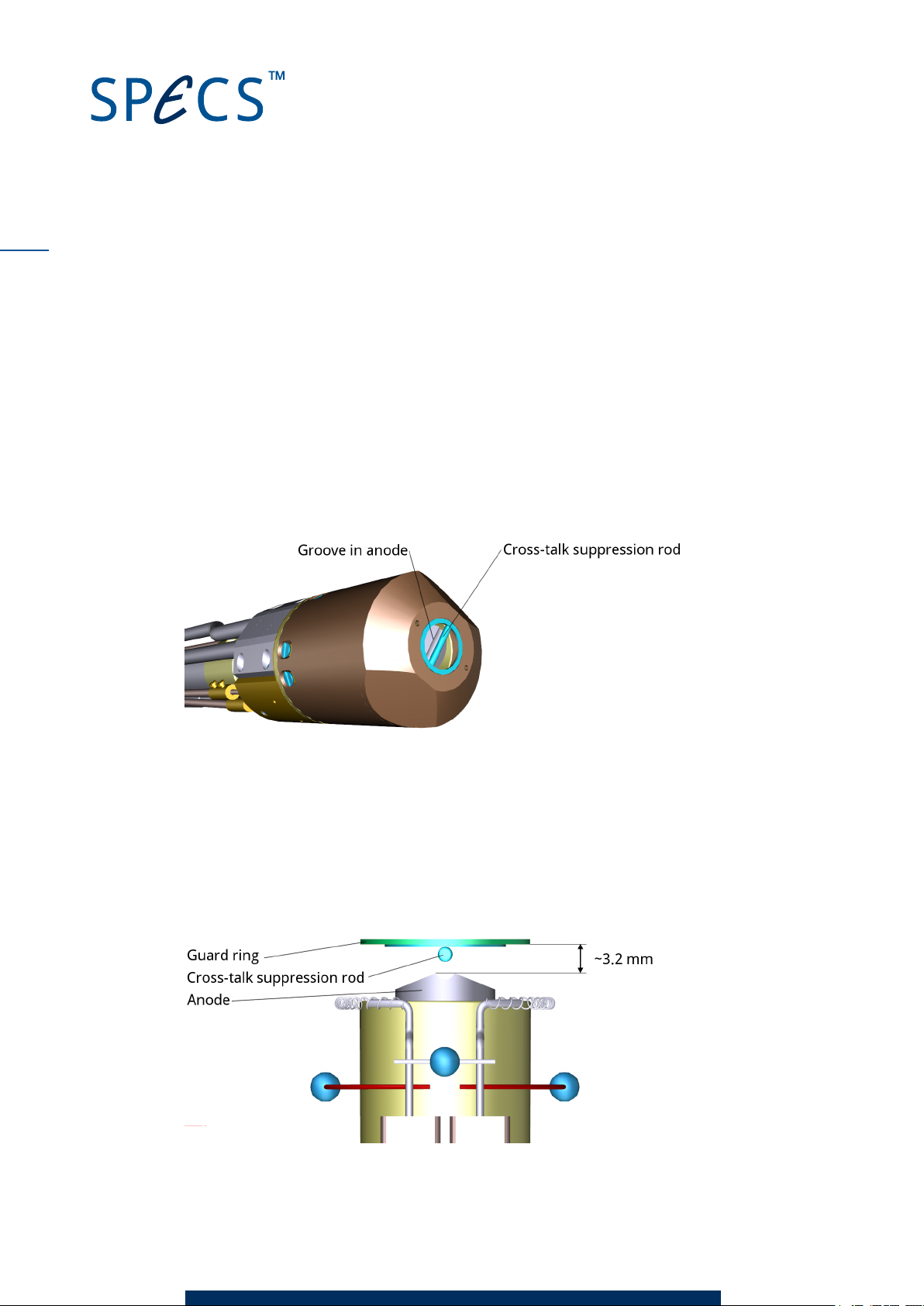
Figure 14 shows the front of the source (without guard ring and aluminium window), with the
correct orientation of the anode.
Figure 14: Correct orientation of anode
Insert i o n dep th o f ano d e i n co rrect
If the distance between the anode and the cross-talk suppression rod is incorrect, it is possible
to generate X-rays from the other anode. In this case, you need to remove the source from the
chamber and check this distance. Figure 15 is a cutaway that shows the correct distance
between the top of the anode and the top of the copper cap (or underside of the protection
ring).
Figure 15: Distance of anode to cross-talk suppression ring
XR 50 V3.1 | May 02, 2016
Page 29

To adjust the cap position:
Loosen the eight screws in the cap and slide the cap to the correct position. You can then
tighten the screws.
Figure 16: Setting the cap position
Caution!
Do not damage the surface of the anode.
23
XR 50 V3.1 | May 02, 2016
Page 30
24
This page intentionally left
XR 50 V3.1 | May 02, 2016
Page 31
Chapter 5 – Maintenance
The major working parts of the XR 50 are easily accessible and can be replaced in a normally
equipped laboratory. This chapter describes the maintenance tasks that you may need to per-
form.
For prices and delivery of spare parts, please contact SPECS. If you have any questions con-
cerning these procedures or need further assistance, SPECS support is glad to help.
Warning—Harmful!
Products returned to SPECS for repair or maintenance should be free of haz-
ardous substances, e.g. radioactive, toxic, caustic or microbiological. If such
contaminants are present, they must be declared. A suitable form is included
at the end of this manual.
Note
SPECS offers a complete cleaning, overhaul and testing of your XR 50 upon request. This ser-
vice includes anode and filament replacement, water inlet replacement or refurbishment if
necessary, and thorough testing with a specification report.
25
5.1 X-Ray Sou rce Chec k
If you remove the XR 50 for maintenance, you should place the source on a flat, clean surface.
The XR 50 can rest on the anode flange and water inlet/ outlet connectors or differential pump-
ing flange. Do not rest the source on the filament feedthrough!
If you remove the anode flange, the change in distribution of weight will cause the source to
rest on the head. In this case, make sure the filament is not damaged.
We recommend performing the following preliminary checks:
Check the resistance and appearance of the cathode.
Is the Al window in good condition? Are there holes or contamination from either the
sample or anode side? If the Al window has been damaged by a pressure difference, the
lost Al foil must be located, otherwise electrical contact between the anode and the groun-
ded XR 50 body can occur.
Is the anode centering bushing contaminated? Measure the resistance between anode
and body.
XR 50 V3.1 | May 02, 2016
Page 32
26
Is the anode centered or misaligned? If so, you will need to remove the copper cathode
cap. If you identify any damaged or malfunctioning parts, replace or refurbish these com-
ponents in order to avoid problems in the future.
5.2 Replacin g th e Anode
Two anodes are available, offering alternative excitations. These are mounted on the end of a
rod that is attached to the water cooling and HVflange at the back of the source. You can
remove this without needing to remove the entire X-ray source from the vacuum system.
Note
Avoid dust contamination on the anode. When high voltage is applied, local areas of high field
intensity, caused by specks of dust, can lead to sparking.
Danger—High Voltages Present!
It will take 3 minutes before all high voltages are absent in the system. Wait
at least 3 minutes before disconnecting any cables from the power supply or
the X-ray source.
Carry out the following procedure:
1. Remove the protection cap and water connections. Use compressed air to blow any excess
water out of the anode water cooling pipes.
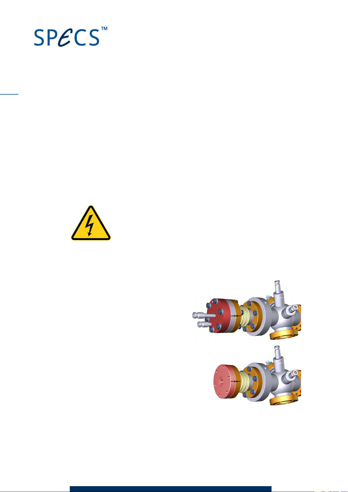
2. Mark the position of the anode flange, as
indicated in the picture, e.g. using a pencil,
marker pen or stickers. The orientation of
the anode is important and you need to be
able to fit the new anode correctly.
3. Remove the anode water cooling flange (high-
lighted red).
4. Remove the anode (flange highlighted red).
Remember that the anode rod is almost the
entire length of the source, so you will need
sufficient space to withdraw the entire anode
assembly.
5. Using the old anode as a guide, find the correct orientation of the new anode. Note the fol-
lowing points:
XR 50 V3.1 | May 02, 2016
Page 33
If the new anode has different excitation surfaces to the old anode, note which cor-
responds to anode 1 and anode 2.
A 180° rotation of the anode will still allow operation; however, you need to remember
that Anode 1 and Anode 2 in the UXC 1000 have swapped their properties (this will
also affect your presets).
6. Reassemble the source in the reverse order, observing the following points:
Use a new DN40CF copper gasket for the anode flange.
A new copper water sealing ring is supplied for the water seal between the anode and
water flanges. This seal only needs to be water-tight, not a vacuum seal. However, a
water leak will create a short-circuit to ground, causing the power supply to trip.
Tighten the screws until you can no longer see the gap between the flanges.
5.3 Replacin g th e Cath ode
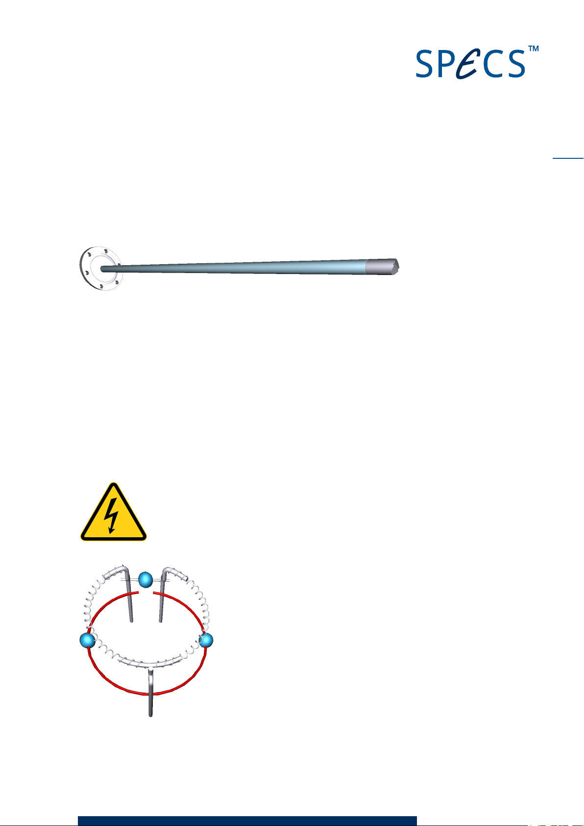
The cathode assembly contains the filament. It is divided into two parts which can be used inde-
pendently for the two anodes. The assembly is mounted at the front of the source. When chan-
ging the cathode, it is necessary to remove the entire X-ray source from the vacuum system.
27
Danger—High Voltages Present!
It will take 3 minutes before all high voltages are absent in the system. Wait
at least 3 minutes before disconnecting any cables from the power supply or
the X-ray source.
Figure 17:Cathode (filament) assembly
XR 50 V3.1 | May 02, 2016
Page 34
28
To replace the cathode:
1. Remove all connections to the source and remove the X-ray source.
2. Unscrew the eight countersunk screws.
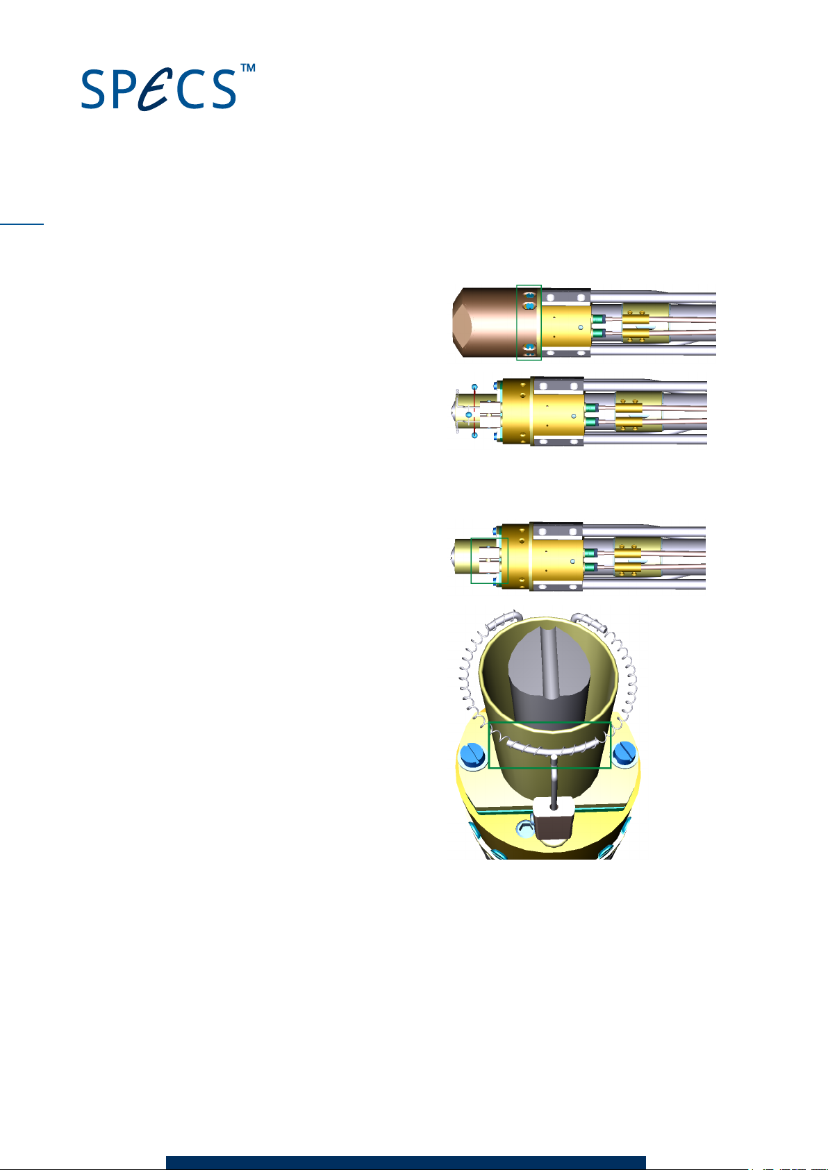
3. Carefully pull off the copper cap. The cop-
per cap should be pulled straight off—do
not tilt the copper cap when removing it.
Leave in place the spacer rings (if installed)
between the cathode cap and the main part
of the head. These rings are for distance
adjustment.
4. Loosen the grub screws that hold the cath-
ode assembly in place.
5. Pull the cathode out of the screw clamps.
6. Insert the new cathode into the supporting
pins until the uppermostpart of the fil-
ament is not quite exposed to the anode.
The part highlighted in the green box
should be close to, but not touching, the
anode protection tube.
7. Check that the filament is as circular as pos-
sible.
8. Tighten the M2 screws.
9. Make sure that the filament has an approximately circular shape. If necessary, carefully
bend the filament support pins.
10. Carefully mount the copper cap onto the head of the X-ray source. The crossover rod below
the Al-window has the same orientation as the anode. Push the cap all the way down so
that it has the same distance as before. Remember to keep the spacer rings in place.
11. Check that the filament is correctly positioned as follows:
XR 50 V3.1 | May 02, 2016
Page 35

Measure the resistance between the filament pin and ground. This should be infinite.
We recommend that you use an audible contact checker with crocodile clips for this
check.
While measuring, rotate the copper cap through 360º. Confirm that there is no contact
between filament and ground while turning.
If there is a short circuit while rotating the cap, remove it and correct the position of
the filament, or bend it inward.
12. Tighten the grub screws.
13. Once again, check that none of the filament pins have a short to ground. Also check that
the filaments are not broken. See Figure 12 on page 21 for the pin assignment of the fil-
ament feedthrough.
Before first use of the filament, degas the filament and both anodes. See "Anode and Filament
Conditioning" on page 12. This procedure ramps up the filament current so that the filament is
not deformed in its first use.
Note
If you are using a filament from another manufacturer, it may be necessary to adjust the
standby current and current limit setting. See the UXC 1000 manual for instructions.
5.4 Replacin g th e Water Inlet
Electrochemical effects make the anode water cooling system susceptible to corrosion. As long
as the anode water cooling connectors are smooth, there is no problem. However, if they show
significant signs of corrosion (deep pits on the connectors), or you experience water leaks, you
should change the water inlet.
29
In the procedure for replacing the anode, the first part to be removed is the water inlet. See
"Replacing the Anode" on page 26 for more information. Note also the following points:
Make sure to note the orientation of the anode before starting.
Even if you do not need to remove the anode, it is a good idea to do so—it will give you the
opportunity to check the condition of the anode.
The length of the cooling tube should fit exactly—you should not need to force the tube
into place.
XR 50 V3.1 | May 02, 2016
Page 36

30
Figure 18: Anode water cooling flange andtube
After fitting the cooling tube, blow into one of the ports to make sure that air flows through. The
pressure required should be similar to that needed to blow up a balloon.
5.5 Replacin g th e Alumi niu m Window
The aluminium radiation window (standard thickness 2 µm) suppresses Bremsstrahlung and
prevents the input of stray electrons generated by the filament from entering the energy ana-
lyzer. Additionally, the X-ray window acts as a barrier between the main chamber and anode
volumes.
The Al window can be torn, perforated or otherwise destroyed by a significant pressure dif-
ference between the source interior and chamber.
When replacing the Al window, it is necessary to remove the entire X-ray source from the
vacuum system.
Danger—High Voltages Present!
It will take 3 minutes before all high voltages are absent in the system. Wait
at least 3 minutes before disconnecting any cables from the power supply or
the X-ray source.
To replace the aluminium window:
XR 50 V3.1 | May 02, 2016
Page 37
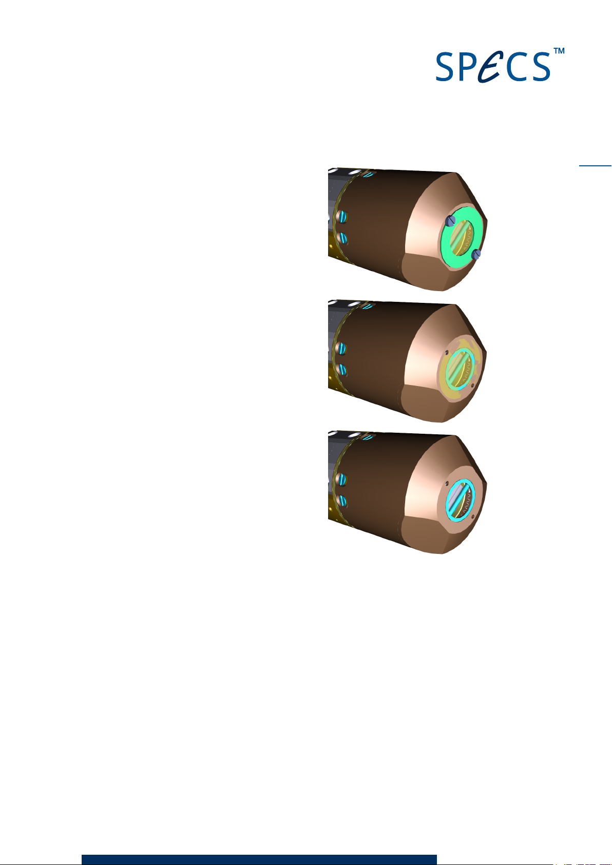
1. Remove all connections to the source and remove
the X-ray source.
2. Remove the two screws and the guard ring from the
source.
3. Carefully pull away the old window, taking care not to
allow any fragments to fall into the source.
31
4. Carefully insert the Al window into the groove of the copper cooling cap and press the win-
dow ring slightly. Make sure that the Al window lies flat on the cooling cap and is not bent.
5. Screw the ring into place.
5.6 Anode Stor age
When the source or the anode is stored in air for extended periods, the surface of the anode
can become oxidized. In order to obtain best performance, this oxide layer needs to be
removed:
Gently scratch the surface of the anode with a glass fiber brush. You only need to remove
the top oxide layer, which is a few microns thick. Take care not to remove the active mater-
ial of the anode.
Use a different brush for each anode material to prevent contamination. Label the brushes
for future use.
XR 50 V3.1 | May 02, 2016
Page 38

32
This page intentionally left
XR 50 V3.1 | May 02, 2016
Page 39

Chapter 6 – Source Overview
The XR 50 is a high-intensity twin anode X-ray source optimized for X-ray photoelectron spec-
troscopy (XPS) experiments, also known as electron spectroscopy for chemical analysis (ESCA).
Figure 19 shows the major parts that make up the XR 50.
33
Figure 19: Source overview
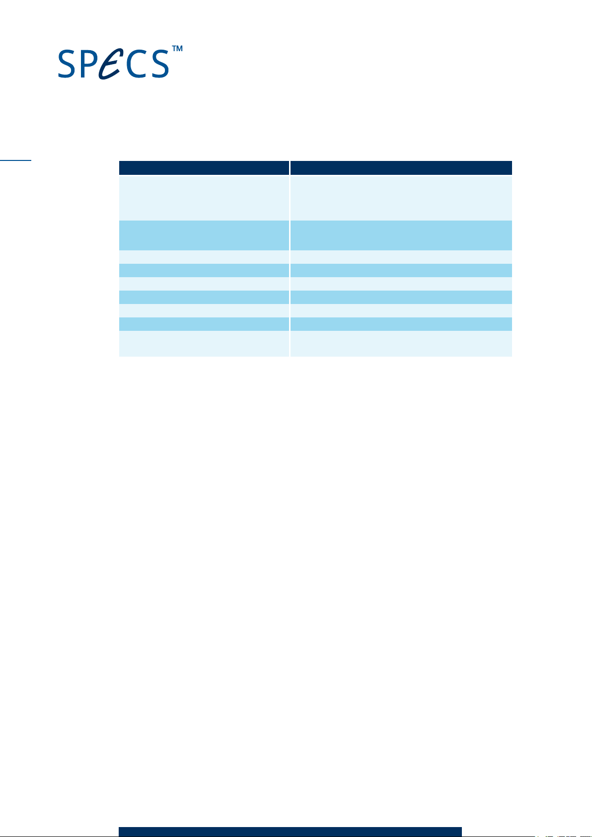
Table 1 lists the features indicated in Figure 19 and offers pointers to further information about
them in this chapter or in other parts of this manual.
XR 50 V3.1 | May 02, 2016
Page 40
34
Feature See section…
Protection cap
Conduit
Safety interlock switch
Jacket cooling
Anode cooling
Differential pumping port "Differential Pumping" on page 6.
Filament feedthrough "Basic Electrical Checks" on page 20
System flange "Vacuum Installation" on page 5.
Anode "Anode" on page 34.
Cathode / filament "Replacing the Cathode" on page 27.
Al window "Replacing the Anode" on page 26.
Anode centering bushing (of interest in
general maintenance procedures)
Table 1: Source features
"Fitting the Protection Cap" on page 8.
"Water Circulation" on page 37 for the mechanical
details of the cooling.
"X-Ray Source Check" on page 25.
6.1 Anode
The XR 50 has a silver-tipped anode coated with two thin films for different excitation energies.
Using silver prevents the presence of Cu Lα breakdown structures that could otherwise com-
plicate the XPS spectra are not expected when the active thin films wear out.
The main advantage of a dual anode is that operation with two different excitation energies
enables a rapid distinction of Auger electron lines from photoelectron structures.
Normally, the two active materials are aluminium and magnesium, although a variety of other
materials are available on request, including the option of two anodes with the same material.
The anodes are manufactured under carefully controlled conditions to guarantee an even and
pure coating with the intended thickness. UHV conditions during deposition ensure very low
levels of oxygen contamination, avoiding additional photoelectron structures and peak broad-
ening.
The following sections contain some operational and reference information about the anode:
Maximum power limits for different anode materials.
Excitation energies for common materials.
The effects of cross-talk between the two anodes.
6.1.1 Operating Limits
The UXC 1000 has default settings that allow safe operation for most anode materials (this
limit is however too high for zirconium anodes). Since some anodes can work at higher powers,
you can change the settings in the power supply. The Limits menu in the UXC 1000 allows you
to set the power limit for each anode. Please see the UXC 1000 manual for more details.
XR 50 V3.1 | May 02, 2016
Page 41
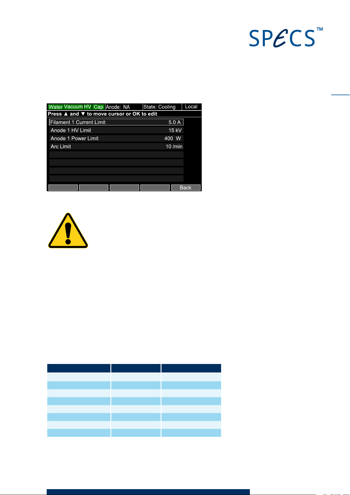
Figure 20: Limitsmenu for setting maximum anode power
Caution!
Do not exceed the maximum operating power for the anode. Too much
power will melt the exciting material.
6.1.2 Excitation Energies
The most commonly employed anode materials are Al and Mg that produce Kα1,2 radiation lines
at energies of 1486.6 eV and 1253.6 eV, respectively. The natural line width is less than 1 eV;
sufficient to determine the binding energies of core levels within 0.2 eV.
35
Low energy X-ray excitation lines (e.g. Zr Mζ) are attractive based on their energies of 132 eV
and 151 eV and their natural line widths of 470 meV and 770 meV, respectively. Their radiation
energies are intermediate between Al/Mg Kα and the quasi monochromatic UV excitations.
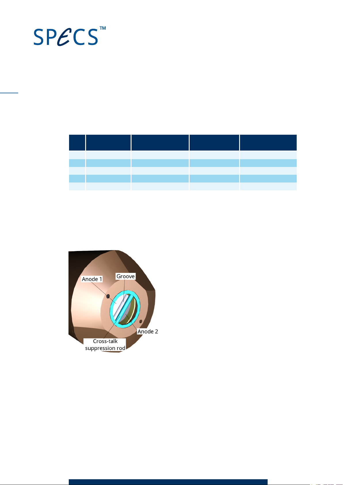
Table 2 shows excitation energies, relative intensities, and line widths of the most commonly
used anode materials.
Element and line Excitation (eV) Line width (eV)
Mg Kα1,2 1253.64 0.68
Al Kα1,2 1486.61 0.85
Zr Mζ 151.4 0.77
Cu Kα1 8055 2.1
Cu Lα 931.6
Cr Kα1,2 5417 2.1
Zr Lα 2042.4 1.7
AgLα 2984.4 2.6
XR 50 V3.1 | May 02, 2016
Page 42
36
Table 2: Main X-ray source excitationlines
Table 3 summarizes the energy shifts and relative intensities of satellite lines of the main excit-
ations.
Line
Energy shift
Mg (eV)
Relative intensity
Mg (%)
Energy shift Al
(eV)
Relative intensity
Al (%)
Kα3 8.4 8.0 9.8 6.4
Kα4 10.1 4.1 11.8 3.2
Kα5 17.6 0.6 20.1 0.4
Kα6 20.6 0.5 23.4 0.3
Kβ 48.7 0.5 69.7 0.6
Table 3: Mg/ Al Kα satellites
6.1.3 Cross-Talk
There is a small rod behind the Al-window which reduces the cross-talk between the excitations
of the two anodes to below 0.35 %. The rod is oriented parallel to the groove at the anode top
which separates the two anode sides from each other.
Figure 21: Cross-talk suppression
A cross-talk spectrum is shown in Figure 22. The peak highlighted in the aluminium spectrum is
due to Mg cross-talk.
XR 50 V3.1 | May 02, 2016
Page 43
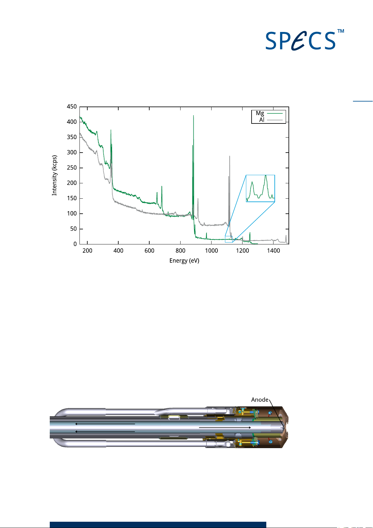
Figure 22: Cross-talk in the XR 50
37
6.1.4 Water Circulation
During operation, several hundred watts of power are dissipated into the small anode area.
Water cooling is essential in order to prevent the anode from melting.
Circuits
There are two cooling circuits in the XR 50.
The anode cooling is shown in the cutaway picture in Figure 23. Two concentric axial tubes form
the cooling circuit—the inner delivers water directly to the anode, while the outer carries it
away. The whole of the anode assembly is at high voltage during operation, leading to a small
current between the anode and ground caused by the water conductivity (see "Water Current"
on page 43).
Figure 23: Anode cooling circuit
XR 50 V3.1 | May 02, 2016
Page 44

38
The head cooling, shown in Figure 24, prevents excessive heating of the source head and its
surroundings. This significantly reduces desorption of adsorbates from the source and cham-
ber walls during operation. As you can see, there are cooling blocks on either side which are
connected with a U-tube.
Figure 24: Heat cooling circuit
6.2 Speci fications
The sections below describe the specifications for various aspects of the XR 50.
6.2.1 Anode
The properties of the anode are listed below.
Property Specification
Material Al, Mg; other materials upon request
Base material Ag-tipped
Voltage +15 kV max. 0–40 mA (with respect to ground)
Power dissipation 1 kW max.
Continuous load Al 400 W, Mg 300 W.
Anode cooling 6 to 8 bar, 2.5–3.5 l/min, 15–22°C
Head cooling Water > 1 l/min, 15–22°C
Water connections ¾" or ½" hoses with Quick Fit connectors
Working distance 15 mm (regular)
Table 4: Anode specifications
6.2.2 Cathode
The properties of the cathode are listed below.
Property Specification
Material Tungsten alloy (to reduce work function)
Power consumption 30 Wmax.
Table 5: Cathode specifications
6.2.3 Operation Range
The maximum allowed temperature and pressure are listed below.
XR 50 V3.1 | May 02, 2016
Page 45
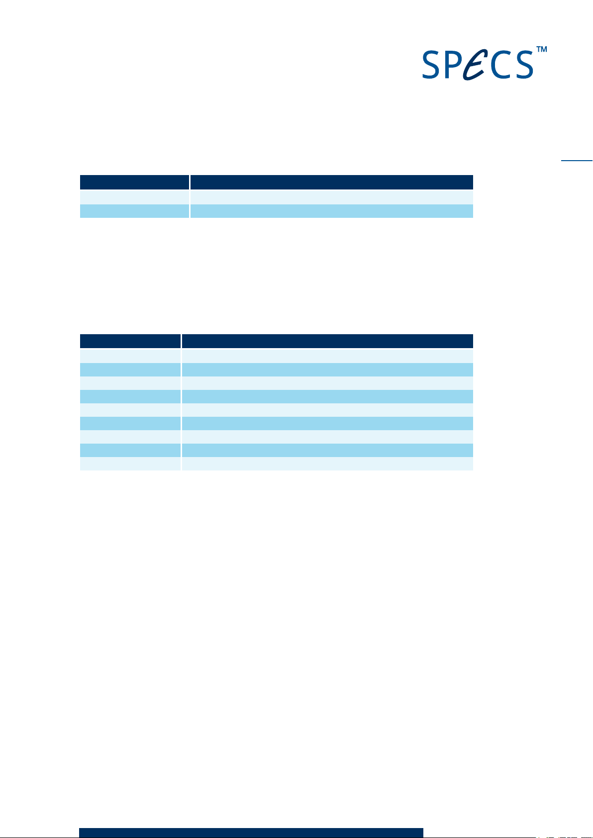
Property Specification
Working pressure 10–6mbar maximum
Bakeout temperature 180 °C without cable connections and protection cover
Table 6: Operationrange specifications
Note
To maximize lifetime, routine operation should be at a pressure of 10–8mbar or lower.
6.2.4 Setup
The specifications below describe the mechanical properties of the source.
Property Specification
Vacuum pumping Via analysis chamber or via separate pumping line
Outer jacket Copper pipes and copper blocks, water-cooled
Anode Exchangeable on flange DN40CF
Radiation window Al, thickness about 1.7–2 µm, pressure proof to 1 mbar difference
Mounting flange DN40CF, larger flanges upon request
Max. diameter 37.8 mm
Z-shift (optional) 50/100 mm
Copper gaskets DN38CF
Weight 10 kg
Table 7: Mechanicalproperties specifications
39
XR 50 V3.1 | May 02, 2016
Page 46
40
This page intentionally left
XR 50 V3.1 | May 02, 2016
Page 47
Chapter 7 – Principles of Operation
The sections in this chapter offer some background details about he operation of the XR 50.
Although not essential for normal use, this information may help you get a better under-
standing of how the source works. The following topics are covered:
A basic description of the generation of X-rays.
Theoretical output intensity from the source.
The voltages and currents involved in the operation of the source.
Magnetic fields in the source.
7.1 Gen eration of X -Rays
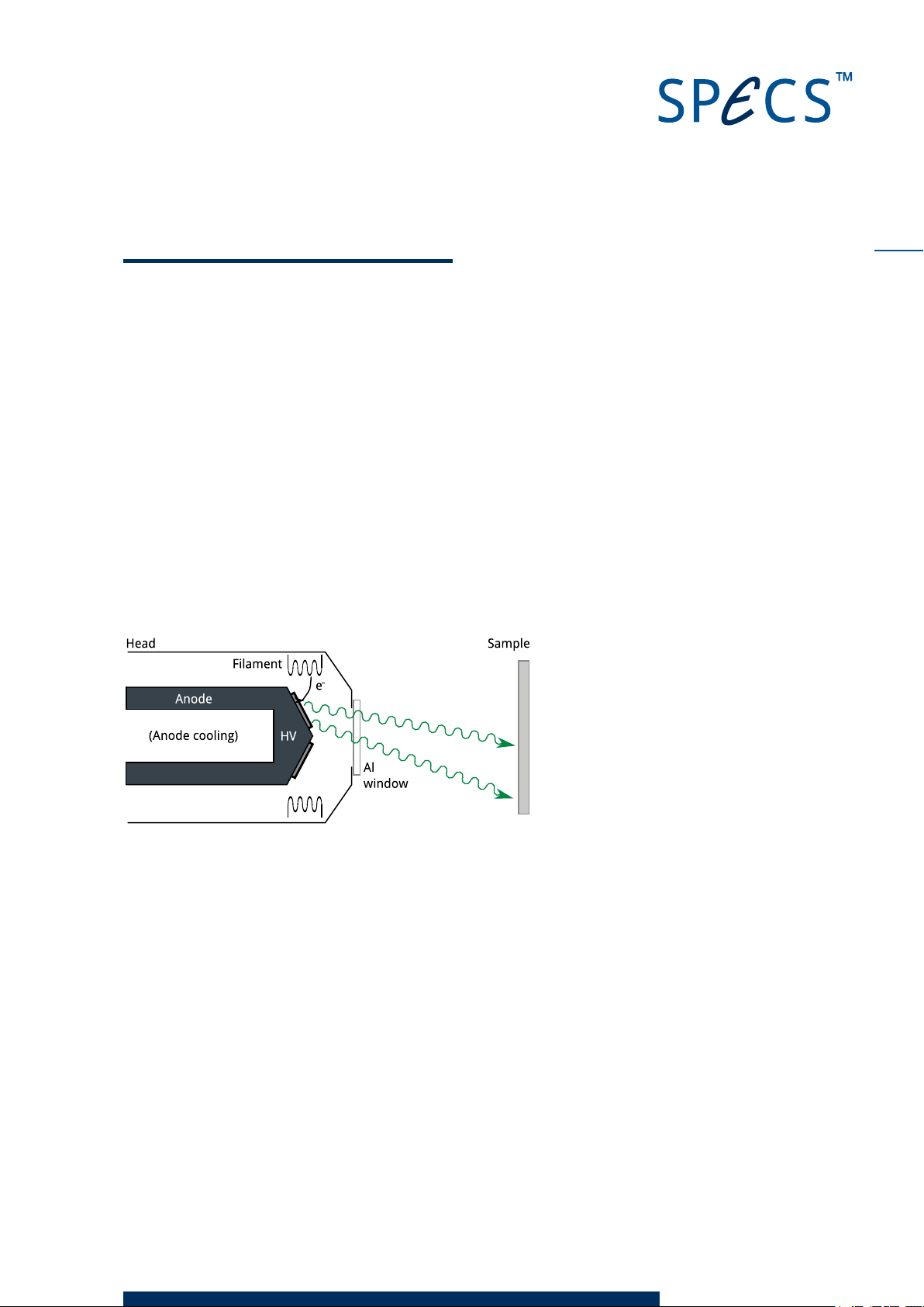
If a solid state material is bombarded with high energy electrons (greater than a few keV), elec-
trons in core levels are ionized. If these vacancies are refilled by electrons from energetically
higher levels, characteristic X-ray radiation is generated.
41
Figure 25: Principle of operation
In addition to this process, Bremsstrahlung—radiation with a continuous frequency spec-
trum—is also produced by retarded electrons.
7.2 Outpu t In tensity
The irradiated area on the sample is elliptical, with an area of 1–2 cm2depending on anode-
sample distance. An unbiased sample current of approximately 0.8 nA per 1 W of Mg Kα X-ray
power is generated by irradiating a clean sputtered Ag target.
If the quantum efficiency η is approximated to unity and a photon density of 5 × 10¹²s–1cm–2is
assumed, 300 Watts of X-ray power can be calculated. A more realistic approximation based on
a yield of η = 0.1 or η = 0.01 will change the value by the factors 10 and 100, respectively.
XR 50 V3.1 | May 02, 2016
Page 48

42
7.3 Voltages and Curren ts
Figure 26 shows the currents and voltages involved in generating X-rays.
UF = Filament voltage
IF = Filament current
IE = Emitter current
IA = Anode current
IW = Water current
UA = Anode voltage
Figure 26: The voltages and currentsinvolvedinthe X-ray source
All of these parameters are displayed on the operating menu of the UXC 1000 when you start a
preset with the exception of the water current, which is shown in the chiller menu (from the
operating menu, select
Menu
then
Chiller
).
7.3.1 Anode V oltage and Current
The output voltage of the UXC 1000 is applied to the source anode. This voltage is the anode
voltage, UA and can be set in the range 0…15 kV.
The anode current is measured directly in the high voltage power supply as the voltage across
a shunt resistor. In the operation of the XR 50, it has two constituents:
Emission current.
Water current.
7.3.2 Emissio n Current
During operation, electrons are emitted from the filament and accelerated toward the anode.
An emission current (IE) flows from the filament through the anode to ground. The amount of
the emission current depends on the filament current (IF) and the acceleration (anode) voltage
(UA) The emission current flows through a shunt resistor to ground allowing the current meas-
urement. The emission control unit of the UXC 1000 measures the emission current and con-
trols the filament current so that a constant emission current is achieved.
7.3.3 Filament Current and V o l tage
The emission control unit of the UXC 1000 supplies the filament voltage, UF, and the filament
current, IF. It is capable of powering the filament up to 10 V/ 8 A.
When the XR 50 is in standby mode, the filament current is set to a lower value. The standby cur-
rent is set so that the emission current in standby mode is around 0.1 mA. Under certain
XR 50 V3.1 | May 02, 2016
Page 49

circumstances, e.g. after changing the filament, the emission current in standby mode may
I I I
= −
W A E
exceed this value.
In order to ensure safe operation of the source, two concurrent regulation circuits are activ-
ated in standby mode. Thus two limits are used for standby mode:
Standby filament current.
Standby emission current.
These two limits are not exceeded at any time. The limit of the emission current in standby
mode is factory set to 0.1 mA.
7.3.4 Water Current
Cooling water is used to transport heat away from the anode and source housing. The cooling
water at the water output of the source has the same potential as the anode and the source
housing. Due to the water conductivity, there is a leakage current, called the water current (IW),
which flows through the water to ground. The amount of this current depends on the water con-
ductivity, as well as the length and thickness of the water hoses.
The water current is calculated in the UXC 1000 from the relation:
43
(1)
The net power of the anode consists of X-ray radiation and heat dissipation. The anode gross
power additionally includes the voltage drop caused by the water current.
The difference between gross and net anode power will increase as water conductivity
increases. At a certain conductivity, the water current where the sum of the emission current
and water current is higher than the available power rating for the UXC 1000. In this case, the
power supply will fail.
If the water resistance is too large (IW < 2 mA at 15 kV), there is a danger of electrochemical
corrosion.
Normal values are in the range 2…10 mA for the water current at 15 kV anode voltage. In order
to ensure stable operation, there needs to be a water current in this range.
7.4 Magnetic Fields
The source is constructed mainly from copper, aluminium and other non-magnetic or dia-
magnetic materials. There is a small residual magnetic field of >0.5 μT.
XR 50 V3.1 | May 02, 2016
Page 50
44
It is necessary to have a small field in the volume between the anode, sample and energy ana-
lyzer in order to produce X-ray excited photoelectron lines of different kinetic energies from the
same element inside the acceptance area.
XR 50 V3.1 | May 02, 2016
Page 51
Chapter A – XR 50 NAP
The XR 50 is also available as the XR 50 NAP. This is a version suitable for measurements in
near ambient pressures (up to 25 mbar).
This appendix provides a short overview of the XR 50 NAP, highlighting the features and oper-
ation modes where they differ from the standard XR 50.
A.1 Constr uction
The XR 50 NAP differs from the standard XR 50 in two ways:
The copper cap on the source head has a different design
The source is surrounded by a metal sheath.
A Viton O-ring is fitted around the copper cap. When the sheath is fitted, this presses against
the O-ring, forming a seal. The sheath is welded to a flange. When it is in place, therefore, the
interior of the X-ray source is isolated from the rest of the vacuum chamber.
There is a thin (0.2 μm) silicon nitride window mounted on the front end of the XR 50 NAP. This
allows the transmission of X-rays while providing a physical barrier between the source interior
and the high pressure in the chamber. The limit on the pressure difference between the
interior of the X-ray source and the measurement chamber is determined by the O-ring and the
window. The window is coated with aluminium on both sides to prevent charging during oper-
ation.
45
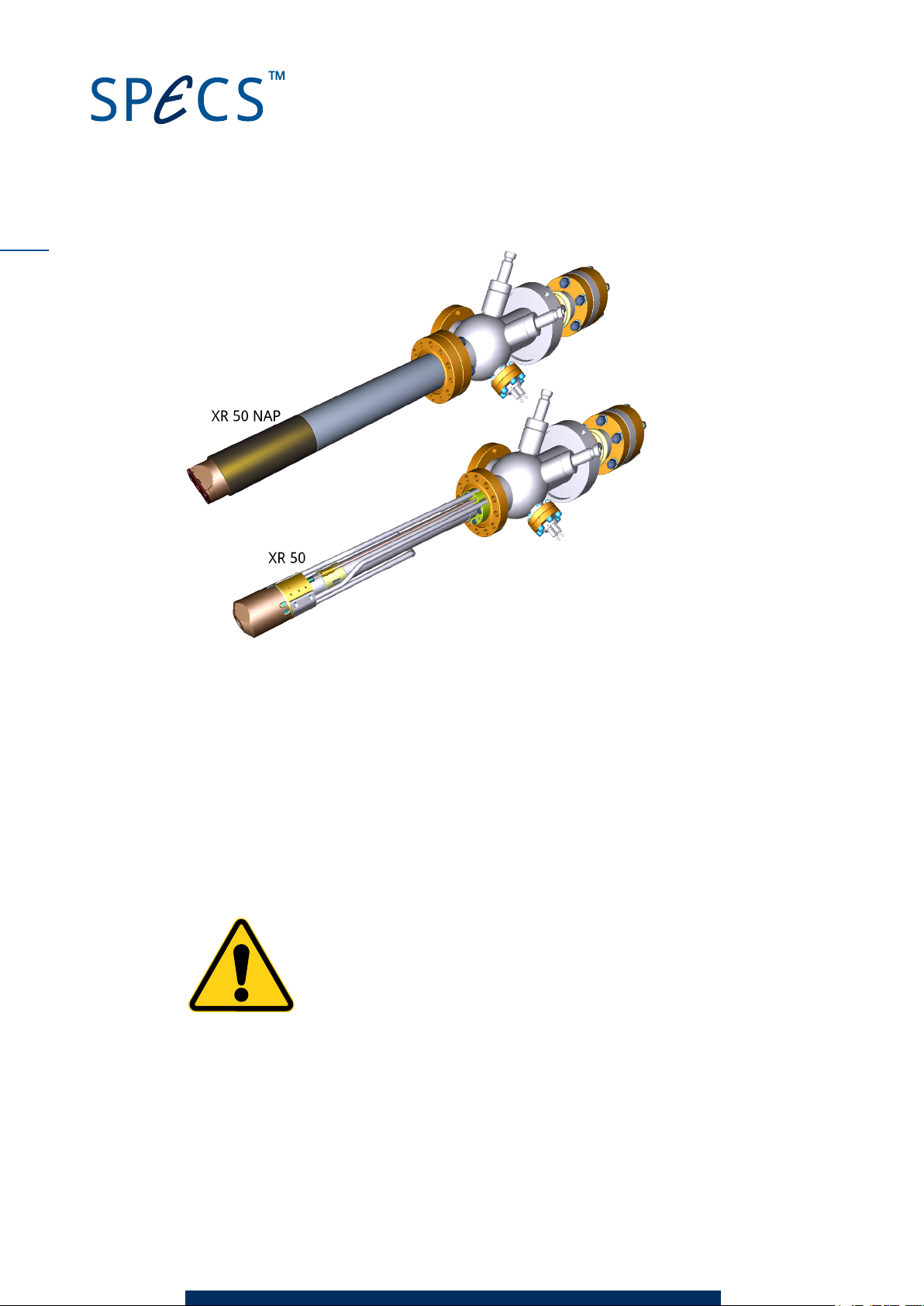
A turbopump needs to be fitted to the pumping port on the source.
Figure 27 shows the XR 50 NAP and the XR 50. You can clearly see the sheath that isolates the
source from the chamber.
XR 50 V3.1 | May 02, 2016
Page 52
46
Figure 27: Construction of the XR 50 H Pand XR50
A.2 Operation
You need to attach a 60 l/s turbopump to the pumping port on the XR 50. This allows a max-
imum pressure in the analysis chamber of 25 mbar. We recommend that you fit a bypass with a
valve between the source and chamber. This valve should be open when the chamber is not
being used for high pressure measurements. This is particularly important when venting the
chamber, in order to prevent a pressure difference across the window.
When degassing the filament, make sure that the cooling water is running. This ensures that
the sheath does not heat up, and thereby prevents any damage to the Viton O-ring.
Caution!
The silicone nitride window on the source is vital in separating the interior of
the X-ray source from the analysis chamber! Tears or perforations in the win-
dow will expose the X-ray source to the elevated pressure in the chamber,
potentially causing damage to the source!
If a high voltage spark occurs during operation, there is a strong possibility that the silicone
nitride window will be damaged. In order to avoid this, we recommend that you use a maximum
anode voltage of 12 kV. This considerably reduces the probability of sparking.
XR 50 V3.1 | May 02, 2016
Page 53
Caution!
We recommend that you do not exceed a bakeout temperature of 120°C in
order to avoid damage to the O-ring.
A.3 Replac i ng the Window
If the window on the front of the source breaks, it is no longer possible to operate the source at
elevated chamber pressures. In such a case, you need to fit a new window, as supplied by
SPECS.
You will need:
Flat-head screwdriver.
Replacement window from SPECS.
Conducting (silver) paint.
In case the anode needs to be cleaned—10 mm wrench (spanner) and new
DN40CFgasket.
To replace the window:
47
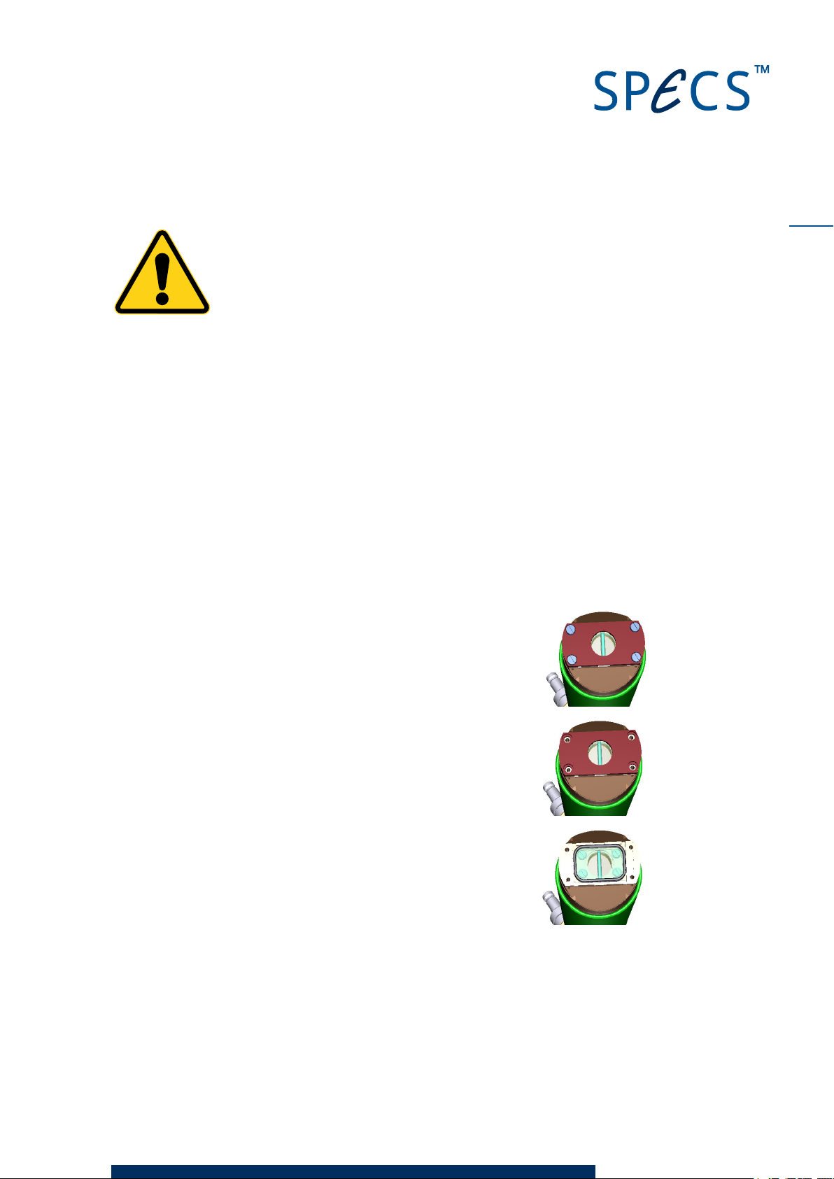
1. Remove the four screws at the source head.
2. Remove the cap from the end of the source that holds the window
in place.
3. Remove the Viton seal on top of the window,
4. Inspect the broken window:
If it is torn, i.e. there is a straight tear across the window, you can simply replace it.
If the window appears to have burst, it is likely that some flakes of the window will
have landed
inside the source. In this case, you need to remove the anode (see "Replacing the
XR 50 V3.1 | May 02, 2016
Page 54

48
Anode" on page 26 for a description of how to remove the anode section) and wipe
away any fragments of the window using a soft cloth or brush.
5. Replace the window, then fit the Viton seal and screw the cap into place.
6. Use a fine paintbrush to paint a thin strip of silver paint between the window and the
source cap (or source body). The window has an aluminium coating to prevent the window
from charging. There needs to be an electrical contact between the window and the body
of the source; however, this only needs to be a thin connection. You will see the paint
applied to the original window—use this as a guide when applying new paint.
XR 50 V3.1 | May 02, 2016
Page 55
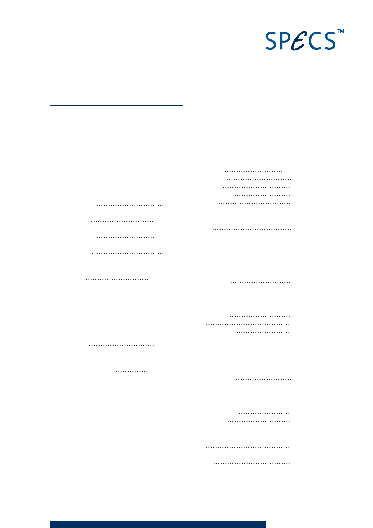
Index
49
4
4-Pin Feedthrough
A
Aluminium Window
Replacing
Anode
Cooling
Current
Replacing
Selecting
Storage
B
Bakeout
C
Cathode
Replacing
Conditioning
Connections
Electrical
Cross Talk
D
Differential Pumping
E
Emission
Excitation Lines
F
Feedthrough
Filament SeeCathode
G
Guard Ring
21
39
30
33, 35, 38
37-38
42
21, 26
16
31
7, 39, 47
34, 38, 41
27
12
10
21, 36
6, 34, 46
17, 42
35
21, 34
22, 31
H
Head Cooling
High Pressure
High Voltage
Hose Connectors
HV Sparks
I
Interlock
L
Line Widths
M
Magnetic Fields
Maintenance
P
Pin Assignment
Power
Power Dissipation
Preset
For Operation
Pressure
Protection Cap
Pumping
High pressure
R
Radiation Window SeeAluminium Window
Relative Intensities
Return/ Repair
S
Safety
Safety Interlock Switch
Satellites
Shutdown
37-38
45
42
38
19
34
35
43
25
20
17
38
15
38
34
46
35
34
36
18
2
2
XR 50 V3.1 | May 02, 2016
Page 56

50
Sparking
Specifications
Standby
19, 46
38
18
T
Troubleshooting
Water
Current
Water Circulation
Water Cooling
Water Current
Water Inlet
Weight
Window
Working Distance
Working Pressure
X-Rays
Excitation Energies
Generation
Z Shift
19
W
43
37
8
43
29
39
45, 47
38
39
X
35
15, 41
Z
7
XR 50 V3.1 | May 02, 2016
Page 57
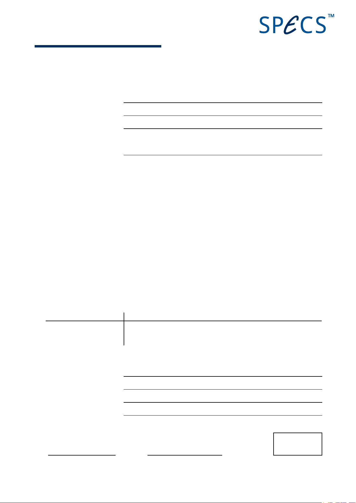
HE ALTH AND SAFETY D E C LARATIO N FOR USED VA CUUM EQU I PMENT AND COMPONENTS
The repair and/or service of vacuum equipment/components can only be carried out if a correctly completed declar-
ation has been submitted for every component.
1. Description of components
Model
Serial number
2. Reasons for return
3. Equipment condition
Has the equipment ever come into contact with the following (e.g. gases, liquids, evaporation products, sput-
tering products…)
Yes No
toxic substances?
corrosive substances?
microbiological substances (incl. sample material)?
radioactive substances (incl. sample material)?
ionizing particles/radiation (α, β, γ, neutrons, ...)?
Is the equipment free from potentially harmful and hazardous substances?
¨ ¨
¨ ¨
¨ ¨
¨ ¨
¨ ¨
¨ ¨
4. Decontamination Procedure
List all harmful substances, gases and by-products which have come into contact with the vacuum equip-
ment/component and the decontamination method used. Continue on a separate sheet if necessary.
Substance Decontamination Method
5. Legally Binding Declaration
Organization
Address
Phone/Fax
Name/Position
I hereby declare that the information supplied on this form is complete and accurate.
Date Signature Company Stamp
SPECS Health and Safety Declaration | Page 1/1
Page 58

 Loading...