

Page 1
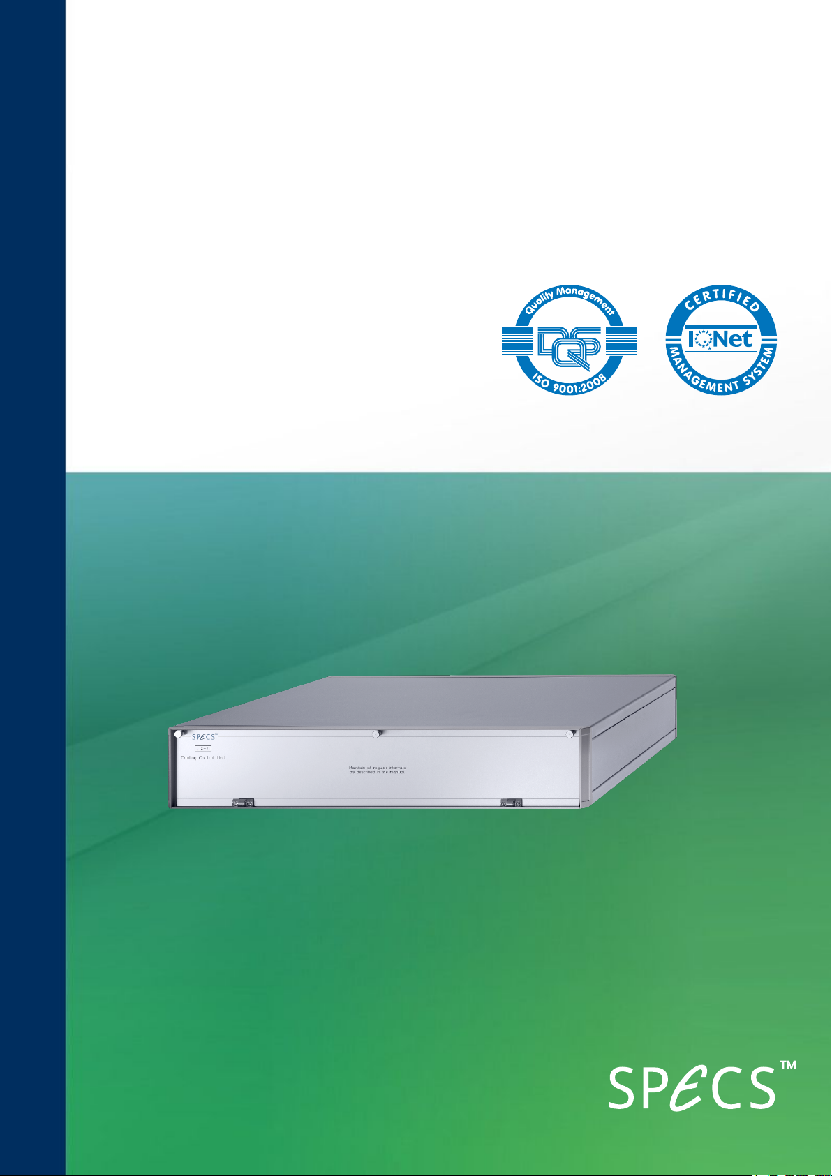
CCX 70
Cooling Water Controller
User Manual V1.1 | 29 April 2016
Page 2

SPECS Surface Nano Analysis GmbH
Voltastrasse 5
13355 Berlin
Germany
Tel:
Fax:
Email:
Web:
+49 30 46 78 24-0
+49 30 46 42 08-3
http://www.specs.com
SPECSUser Manual
CCX 70—Cooling Water Controller for X-Ray Sources, Version 1.1
29 April 2016
SPECS order number reference: 2078000459
©2016. All rights reserved. No part of this manual may be reproduced without the prior per-
mission of SPECS GmbH. Other product and company names mentioned in this document may
be the trademarks or registered trademarks of their respective owners and are used for iden-
tification purposes only.
Page 3
Table of Contents
Chapter 1 – Introduction
1.1 About
1.2 Information
1.3 Safety
1.4 Environmental Operating Conditions
Chapter 2 – Installation
2.1 Rack Mounting
2.2 Connections and Interlocks
2.3 Water Cooling
2.3.1 Fitting the Protection Cap
2.3.2 Head Cooling Circuit
Chapter 3 – Water Supply
3.1 Quality
3.2 Preventing Biological Activity
3.2.1 Algicide
3.2.2 Water Hoses
3.3 Pressure and Flow Rate
3.4 Temperature
3.5 Water Current
iii
1
1
2
3
5
5
6
7
8
11
12
12
12
12
13
13
Chapter 4 – Operation
4.1 Switching On
4.2 The Chiller Menu in the UXC 1000
4.3 Software
Chapter 5 – Troubleshooting
5.1 Water Interlock Problems
5.2 Water Flow Problems
Chapter 6 – Cleaning
6.1 Cleaning the Internal Filters
6.2 Cleaning the Anode Connections
6.3 Cleaning the External Filter
6.4 Cleaning the Water Cooling Circuit
Chapter 7 – Technical Details
7.1 Front Panel
7.2 Rear Panel
7.3 Block Diagram
15
15
16
20
20
23
24
25
26
29
29
31
CCX 70 V1.1 | 29 April 2016
Page 4

iv
7.4 Interior Details
7.5 Specifications
32
33
Index
35
CCX 70 V1.1 | 29 April 2016
Page 5

Chapter 1 – Introduction
Welcome to the user manual for the SPECS CCX 70. This controls and monitors the water cool-
ing for SPECS X-ray sources.
This chapter explains briefly how to use the manual and points you toward further sources of
information.
Most importantly, it contains safety notices that you should read before operating the equip-
ment.
1.1 Abou t
The manual is divided into the following chapters:
Chapter 2 has the installation procedures to get the instrument ready for operation.
Chapter 3 describes the requirements for the cooling water supply.
Chapter 4 covers the normal operating procedures.
Chapter 5 contains a list of error messages and offers some troubleshooting measures.
Chapter 6 has some maintenance procedures.
Chapter 7 contains technical details, including specifications and connector pin assignments.
1
1.2 Information
This manual describes the CCX 70 and its use with X-ray sources. For safe and reliable oper-
ation, you should also refer to the following manuals:
The X-ray source manual for installation, special operating notices and maintenance of the
source.
UXC 1000 manual for information about the power supply, its operation and troubleshoot-
ing procedures.
For further advice and assistance, please also contact SPECS support:
Tel. +49 30 46 78 24-0
email: [email protected]
If you need to return this SPECS product for repair, service or upgrade, please first contact
SPECS support. We will provide you with a Return Merchandise Authorization (RMA) as well as
details for correct packaging and shipment of the instrument. This will ensure safe trans-
portation and speedy processing.
CCX 70 V1.1 | 29 April 2016
Page 6
2
1.3 Safety
The document "Safety Instructions"is contained with this instrument. This contains important
warnings and procedures that you should adopt when using SPECSequipment.
In addition to the advice in the safety instructions, warnings and cautions are included in this
manual at appropriate places. Please observe these warnings for your own safety and to
ensure reliable operation of the equipment.
Danger—High Voltages Present!
Beware! Hazardous voltages are present. Lethal high voltages up to 15 kV
are applied to the X-ray source.
The water and voltage conduit from the CCX 70 carries high voltages up to 15 kV! It is important
to comply with the following safety directives:
Use only original cables, connectors, and flexible conduits supplied by SPECS. Make sure
that all cables and water lines are without physical or electrical defects.
Make sure the power supply is grounded with a proper HF cable.
Only operate the source with the protection cap in place. Do not modify the protection cap
in any way.
Do not override or defeat the interlocks in any way.
Never operate the power supplies with the case open.
Connect the high voltage cable only when the power supplies are turned off.
After switching off the power units, wait a minimum of 3 minutes before making dis-
connections or opening power supplies or the X-ray source protection cover.
In the event of a water leak in the CCX 70, make sure that all parts are dry before attempt-
ing to operate the source again.
Operating the CCX 70 with equipment other than that delivered by SPECS may void your
warranty. Contact SPECS for advice.
If you need to return the instrument to SPECS for repair, please fill out the declaration at the
end of this manual.
CCX 70 V1.1 | 29 April 2016
Page 7

1.4 Envi ronmental Oper ating Conditions
The equipment must be installed in a dry, dust free laboratory. The following conditions are
required for operation.
Temperature (normal system operation):
absolute limit range: 15–30 °C (60–85 °F)
recommended range: 20–25 °C (68–77 °F)
Relative humidity:
absolute limit values: 40–80%
recommended range: 50–60%
There must be no condensed water on the equipment.
Atmospheric pressure:
800–1200 mbar
Air conditioning is advisable in order to ensure the ambient requirements, especially for dis-
sipating heat produced by the equipment.
3
CCX 70 V1.1 | 29 April 2016
Page 8

4
This page intentionally left blank.
CCX 70 V1.1 | 29 April 2016
Page 9

Chapter 2 – Installation
This chapter describes the steps required to set up the CCX 70 so that the water cooling is
ready for activation. You should also refer to the source manual for details of the vacuum
installation and bakeout, as well as any warnings and special requirements for your source.
Installation involves the following steps:
Fitting the unit in a rack.
Water connections.
There is also some information about the interlock conditions that need to be fulfilled before
the instrument can be activated.
2.1 Rac k Mou ntin g
The CCX 70 fits into a standard 19" rack. You should observe the following points:
Mount the CCX 70 at the bottom of the 19" rack. In the event of a water leak, no other elec-
tronic units will be damaged.
Fit the unit into the same rack as the UXC 1000 for ease of connection.
Connect a hose to the Water Drain outlet on the rear panel in case of a water leak inside
the unit. Lead the outflow of this hose away from the rack.
Arrange the water hoses and the grounding cable so that the CCX 70 can be pulled out of
the rack for service purposes.
5
2.2 Connections and Interl ocks
For details of the electrical connections, please refer to the manual for your source.
The XR 50 is protected by a number of interlocks, most of which are handled by the CCX 70. The
interlock status is sent to the UXC 1000, which will only operate if all interlocks are safe. In the
event of an interlock trip, the UXC 1000 will show an error message detailing the problem.
It is helpful to know what these interlocks are when setting up the source:
Water—there is a flow meter and temperature sensor inside the CCX 70 to monitor the
water flow and temperature. The signals are sent to the UXC 1000. If the values fall out-
side the limits set in the UXC 1000, source operation is stopped.
HV—the HVcable must be plugged into the back of the UXC 1000 before the high voltage
can be activated in the UXC 1000.
Protection cap—there is a microswitch on the protection cap that is closed when the
cap is correctly fitted. The high voltage can only be activated when this switch is closed.
CCX 70 V1.1 | 29 April 2016
Page 10
6
Internal water detector—stops operation in the event of a water leak inside the CCX
70.
Front panel maintenance cover—this needs to be closed correctly before operation
can occur.
The UXC 1000 can also be connected to an interlock sensor, e.g. a pressure measurement
gauge. If this interlock is not in use, it needs to be bridged with a terminator (supplied).
If the XR 50 is correctly connected and the conditions described in this chapter are met, these
interlocks are safe and the XR 50 can be operated.
Caution!
Do not attempt to defeat the interlocks. Death, serious injury or severe dam-
age to the source can result if the interlocks are overridden.
2.3 Wa ter Coolin g
The XR 50 has the following requirements for the cooling water:
Flow rate: >2.5 l/min
Temperature: 20 ºC
There are a number of other important additional considerations for cooling water. These guar-
antee a long lifetime of the source as well as describing possible problems that might appear
during operation. Please read the chapter "Water Supply" on page 11 for a complete descrip-
tion of the water requirements.
Caution!
If several items of equipment share the cooling water supply (pumps, etc.),
make sure that the pressure and temperature is adequate and fulfills the
cooling requirements for all instruments.
The cooling requirements vary according to the source. The XR 50 and XR50 M have two cool-
ing circuits:
Anode. This circuit is made when you fit the protection cap over the source.
Head. The connectors are on the body of the source, near the system flange.
The XR-MF only has a cooling circuit for the anode. Nevertheless, you should read the section
"Head Cooling Circuit" on page 8 as it contains useful information about connecting a closed-cir-
cuit chiller. Please also see the XR-MF manual for more details.
CCX 70 V1.1 | 29 April 2016
Page 11
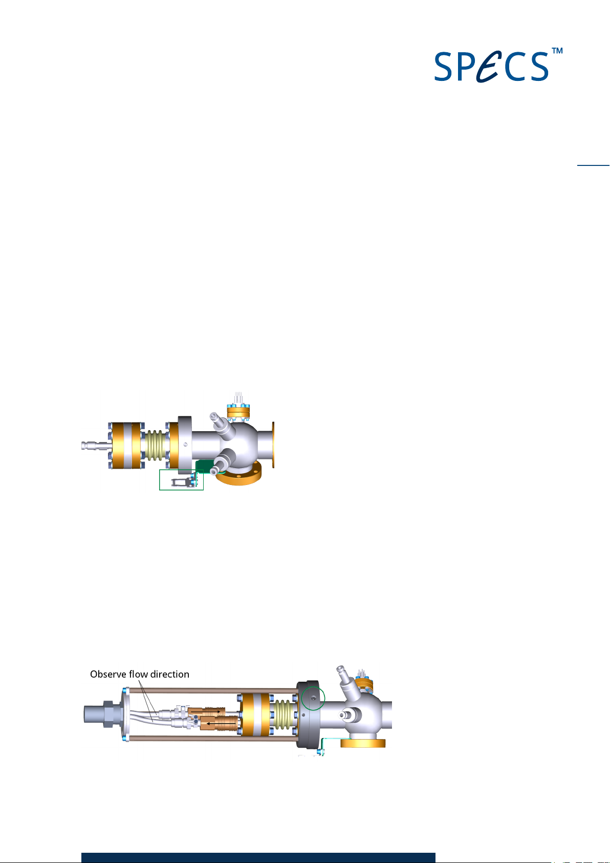
2.3.1 Fitting the Protection Cap
During operation, the top flange of the XR 50 is at high voltage. For safety reasons, a protection
cap prevents access to this flange. A safety interlock switch mounted on the side of the cap is
closed when the cap is correctly in position. The high voltage can only be activated when this
switch is closed.
The picture below shows the source head before fitting the protection cap. Note the position of
the safety switch contact (marked with a green box) . You need to use this for orientation of the
protection cap.
Note
Depending on the model, your source may appear to be different to that shown in the picture.
This does not affect the procedure for fitting the cap.
7
To fit the protection cap:
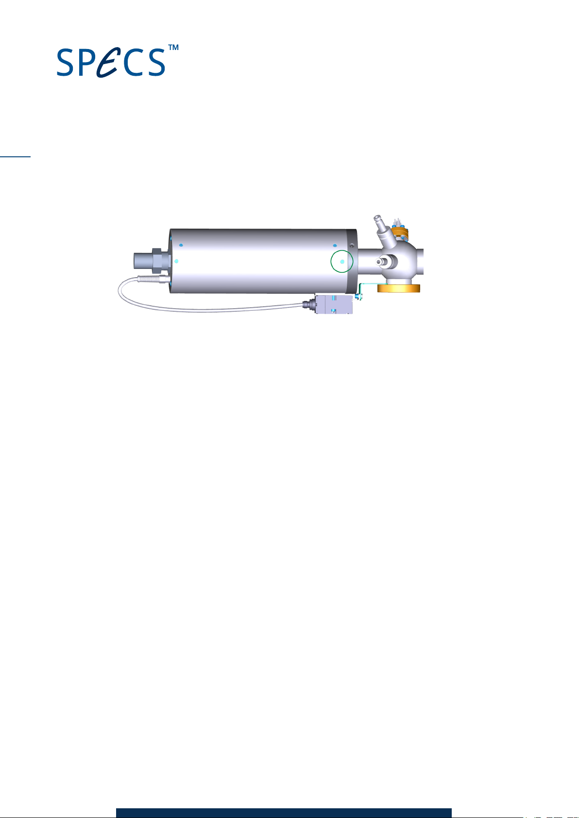
1. Fit the support frame over the source flange and tighten the three grub screws to fix it into
place. This supports the weight of the conduit while connecting the water hoses.
2. Fit the water hoses onto the cooling pipes, making sure to observe the correct flow dir-
ection. The hoses and pipes are labeled with arrows. The center (longer) pipe is for water
flowing into the source.
Note
The high voltage connections are also made when you fit the hoses.
CCX 70 V1.1 | 29 April 2016
Page 12
8
3. Slide the protection cap over the frame so that the contact fits into the safety switch.
4. Secure the protection cap with the three screws around the side of the cap.
Removing the protection cap is the reverse of the above. Note the following points:
When pulling the cap away from the head, take care not to strain the cable for the safety
switch interlock.
Always disconnect the water connectors before removing the support frame. Without the
frame, the weight of the conduit can damage the water hoses.
2.3.2 Head Cooling Circuit
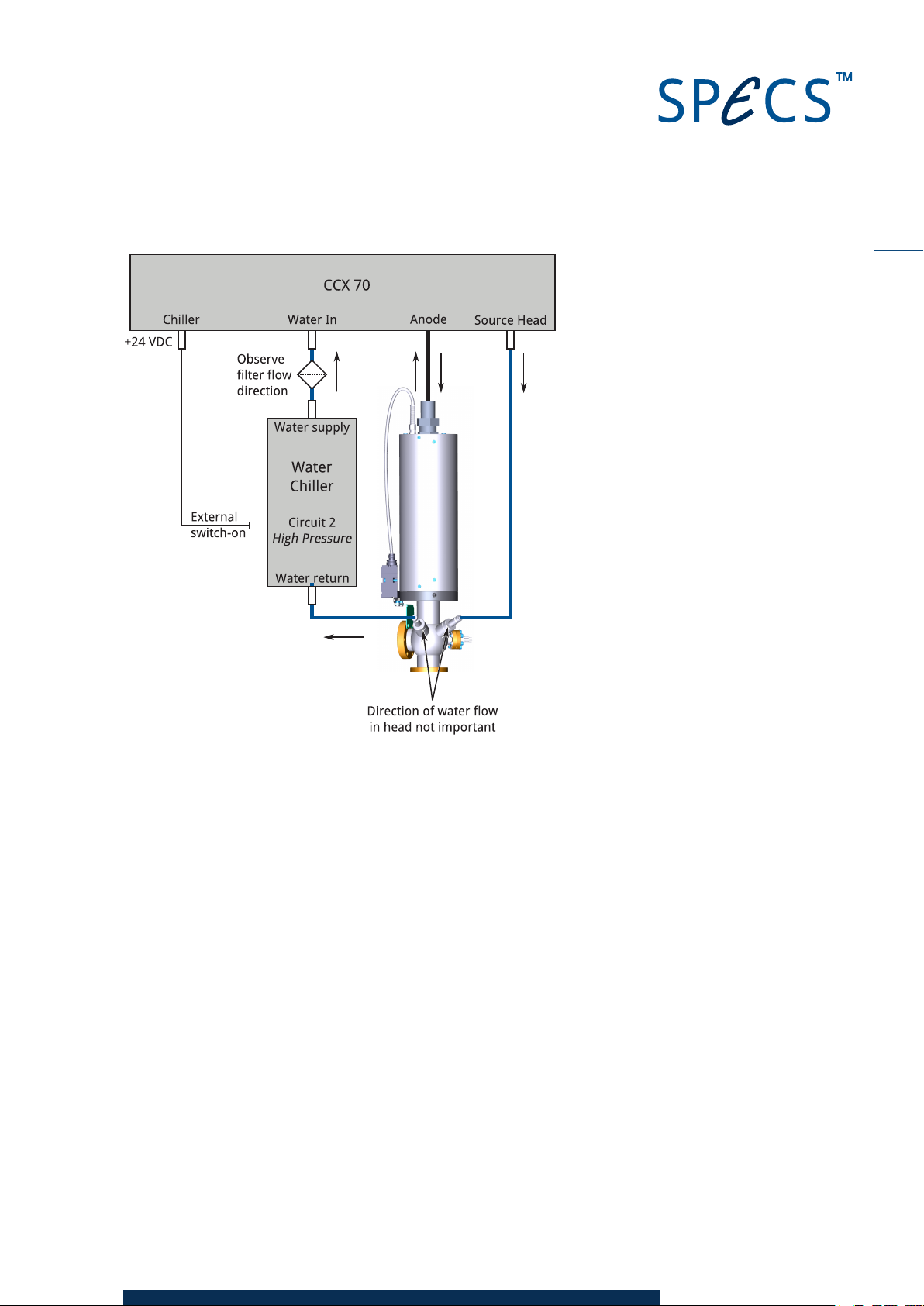
SPECS recommends a water chiller to supply water to both cooling circuits on the source. Fig-
ure 1 shows the connection scheme for the water cooling.
The Chiller output on the CCX 70 supplies a +24 VDC signal when the cooling is activated. This
switches the power supply to the water chiller.
If you are not using a water chiller, e.g. tap water or another installed water supply, the con-
nection scheme is essentially the same, with your water supply in the place of the water chiller.
CCX 70 V1.1 | 29 April 2016
Page 13
9
Figure 1: Connection scheme for water cooling
CCX 70 V1.1 | 29 April 2016
Page 14

10
This page intentionally left blank.
CCX 70 V1.1 | 29 April 2016
Page 15
Chapter 3 – Water Supply
Adequate water cooling is critical for the reliable operation of the X-ray source. Failure to
provide suitable cooling can lead to unstable operation and severely reduced lifetime of the
source.
Caution!
Experience shows that a common reason for equipment failure is inad-
equate cooling. It is vital that you observe the information in this chapter con-
cerning the properties of the cooling water.
The following topics are particularly important for the cooling water:
Make sure the water is clean and free of contaminants.
Prevent biological activity in the water system.
Ensure that the water pressure and flow rate is correct.
Maintain the water temperature within the correct operating range.
Check the source frequently for signs of corrosion.
Make sure the water current is within the accepted range for stable operation.
11
This chapter describes the above points in more detail. Please also refer to "Cleaning" on page
23 for details about the regular maintenance procedures. It is also necessary to clean the
source frequently to ensure the quality of the cooling water.
3.1 Qua lity
It is essential to use clean water for cooling:
Do not use polluted or dyed water.
If there are particles in your water supply, fit a filter.
Do not use salt water, as it will promote corrosion.
Distilled water is not advisable, as it can cause corrosion in the chiller. Its low conductivity also
means that there is a low water current, leading to unstable operation.
Clean tap water is recommended for the cooling water. If you have doubts about the quality of
your mains water supply, you should use distilled (or deionized) water and add bottled mineral
water until the water current reaches the normal range (2…10 mA).
CCX 70 V1.1 | 29 April 2016
Page 16
12
Caution!
Contaminants in the water supply can reduce the cooling efficiency, leading
to increased operating temperatures. This can cause damage to the source.
Refer to "Cleaning" on page 23 for details about regular checks and cleaning
procedures to avoid the accumulation of contaminants.
Note that particles and chemical compounds will be formed in solution by electrochemical pro-
cesses. These are deposited as sediments. For this reason, you need to clean the filters and
check the water quality periodically, replacing water as necessary.
3.2 Pr eventin g Bi ologi cal Activity
It is vital to hinder the growth of microorganisms in the cooling water. These can:
Promote corrosion inside the source.
Cause blockages and reduced water flow.
Create insulating layers, reducing the effectiveness of the cooling water.
3.2.1 Algicide
SPECS recommends the use of an algicide to prevent the growth of algae, bacteria and fungus
in the cooling water. This is essential when using a closed circuit water chiller. Please see the
water chiller documentation for more details about using an algicide.
Warning—Harmful!
Avoid contact with anti-algeon. Irritations of skin and mucosa are possible.
3.2.2 Water Hoses
SPECS supplies dark, opaque hoses with the CCX 70. These prevent light from reaching the
water and thereby reduce biological activity.
Note
If the X-ray source is out of use for long periods of time, remove the hoses and blow the water
out of the source. This will avoid possible sedimentation effects.
3.3 Pr essu re an d Flow R ate
The CCX 70 contains a pressure meter and a flow meter to monitor the static water pressure of
the inlet line as well as the rate of water flow through the system. The water inlet valve is con-
trolled by the UXC 1000. The reading of the pressure meter is read by the CCX 70 and can be
displayed by the UXC 1000.
CCX 70 V1.1 | 29 April 2016
Page 17
If several instruments use the water cooling supply, the water flow rate, temperature, and pres-
Water resistance
I
F
U
F
I
W
U
A
I
A
I
E
e
-
Filament Anode
sure need to be checked. In this case, water cooling for the instruments needs to be set up in a
shunt arrangement. Make sure that all instruments receive adequate cooling.
Caution!
The minimum flow rate for the XR 50 is 2.5 l/min. Do not operate the source
with a lower flow rate, as severe damage can result.
3.4 Temperatur e
The cooling water temperature is important for reliable operation. The recommended water
temperature range is 15–22 ºC, with a nominal temperature of 20 ºC.
You should avoid water temperatures outside this range:
Lower temperatures can easily cause condensation on the source (depending on the dew
point), leading to flashovers of the anode HV to ground.
Higher temperature may result in overheating of the source, leading to evaporation of the
anode or—in the worst case—a cracked anode with a water leak into the chamber.
The water temperature is displayed in the Chiller menu of the UXC 1000. You can also set the
lower and upper temperature limits in this menu.
13
3.5 Wa ter Cur ren t
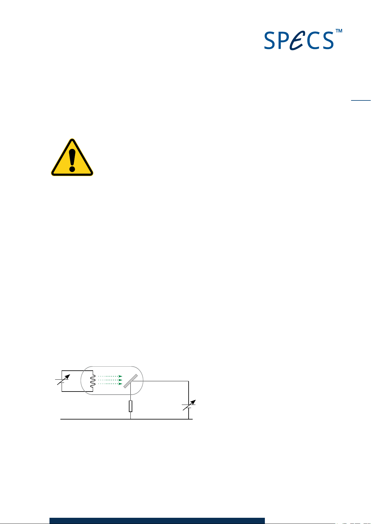
Figure 2 shows the principle of operation of an X-ray source. Of particular interest in this sec-
tion is the water resistance. During operation, the anode is at a potential of up to +15 kV. Due to
the finite conductivity of the anode cooling water, there is also a current that flows through the
water to ground.
UF = Filament voltage
IF = Filament current
IE = Emitter current
IA = Anode current
IW = Water current
UA = Anode voltage
Figure 2: Operationof X-ray source
For stable operation, the water current should be in the range 2…10 mA. You can monitor the
water current in the Chiller menu of the UXC 1000.
CCX 70 V1.1 | 29 April 2016
Page 18

14
Water current to o lo w
If the water current is too low, electrochemical attacks at the anode can occur.
The easiest way to reduce the water resistance is to add a small amount of tap water or min-
eral water to the cooling water. Alternatively, a small quantity of copper salt (sulfate, nitrate)
can provide the necessary conductivity.
Water current to o high
The power delivered by the source is given by the anode current and anode voltage. However,
the power supply is limited by the amount of emission current it can deliver. If too much current
is being lost as water current, the power output from the source drops.
In order to reduce the water current, you should add deionized or distilled water. If you are
using tap water and the water current is too high, you need to change the water supply—a
closed circuit system offers the best solution in this case.
High water current can also be caused by contaminants in the cooling water. In this case, per-
form some cleaning cycles with tap water to wash the cooler and the water lines, then refill the
cooler with deionized or distilled water.
CCX 70 V1.1 | 29 April 2016
Page 19

Chapter 4 – Operation
The CCX 70 is controlled by the UXC 1000. In addition to switching the water cooling on and off,
the UXC 1000 can display the status of the CCX 70 and allows you to set parameters such as
the water flow and temperature limits.
This chapter contains the basic information relevant to the CCX 70. For more information,
please refer to the UXC 1000 manual.
4.1 Swi tc hi ng O n
There is no power switch on the CCX 70—it is switched on by the UXC 1000.
Switching the water cooling on and off is also controlled by the UXC 1000. When you activate a
preset, a valve inside the CCX 70 opens, allowing water flow through the cooling circuits. If you
have a water chiller, this will also be switched on.
To stop the water cooling, use one of the following methods:
Press
Switch off the UXC 1000.
Shutdown
on the UXC 1000.
15
The Chiller menu enables you to switch the water on and off without starting source oper-
ation—see the following section.
4.2 Th e Chiller Me nu in th e UXC 1000
The UXC 1000 uses a menu control system. One of these menus contains information about
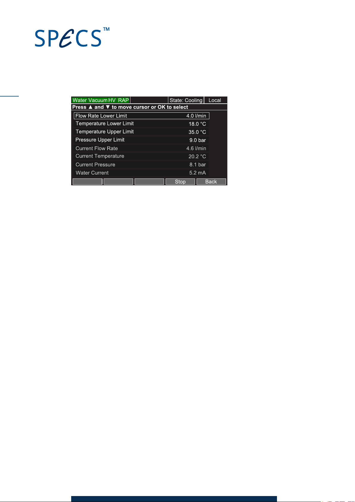
the CCX 70. This menu shows the flow rate, temperature and pressure limits as well as the
operating parameters read from the CCX 70.
You can access the chiller menu in the following ways:
Switch on the UXC 1000, move the cursor to
During operation, press the
Chiller menu as above.
There are two softkeys in the menu:
Start/Stop
depending on the cooling status. The
cooling. This option is not available if the unit is in standby or operating mode.
Back
. Activates and deactivates the water cooling. The label on the softkey changes
. Returns to the previous menu.
Menu
softkey to enter the main menu and then select the
Chiller
and press ► to enter the Chiller menu.
State
in the infobar shows the current status of the
CCX 70 V1.1 | 29 April 2016
Page 20
16
Figure 3: Chiller menu
You can edit the following parameters:
Flow rate lower limit.
Temperature lower limit.
Temperature upper limit.
Pressure upper limit.
To edit parameters in the Chiller menu:
1. Use the ▲ and ▼ keys to move the cursor to the parameter you want to change.
2. PressOKto edit the parameter.
3. Turn the encoder wheel to set the value.
4. PressOKto accept the value.
The following parameters are grayed out and are read-only:
Current flow rate.
Current temperature.
Current pressure.
Water current.
4.3 Software
SpecsLab Prodigy has facilities for controlling an X-ray source via the UXC 1000. You can view
the properties of the CCX 70 in the device control for the UXC 1000 as well as setting limits for
the cooling water.
Note
You need to configure SpecsLab Prodigy so that the UXC 1000 device control is available.
Please see the SpecsLab Prodigy Quick Guide for information about using the SpecsLab Prodigy
Config Tool.
CCX 70 V1.1 | 29 April 2016
Page 21
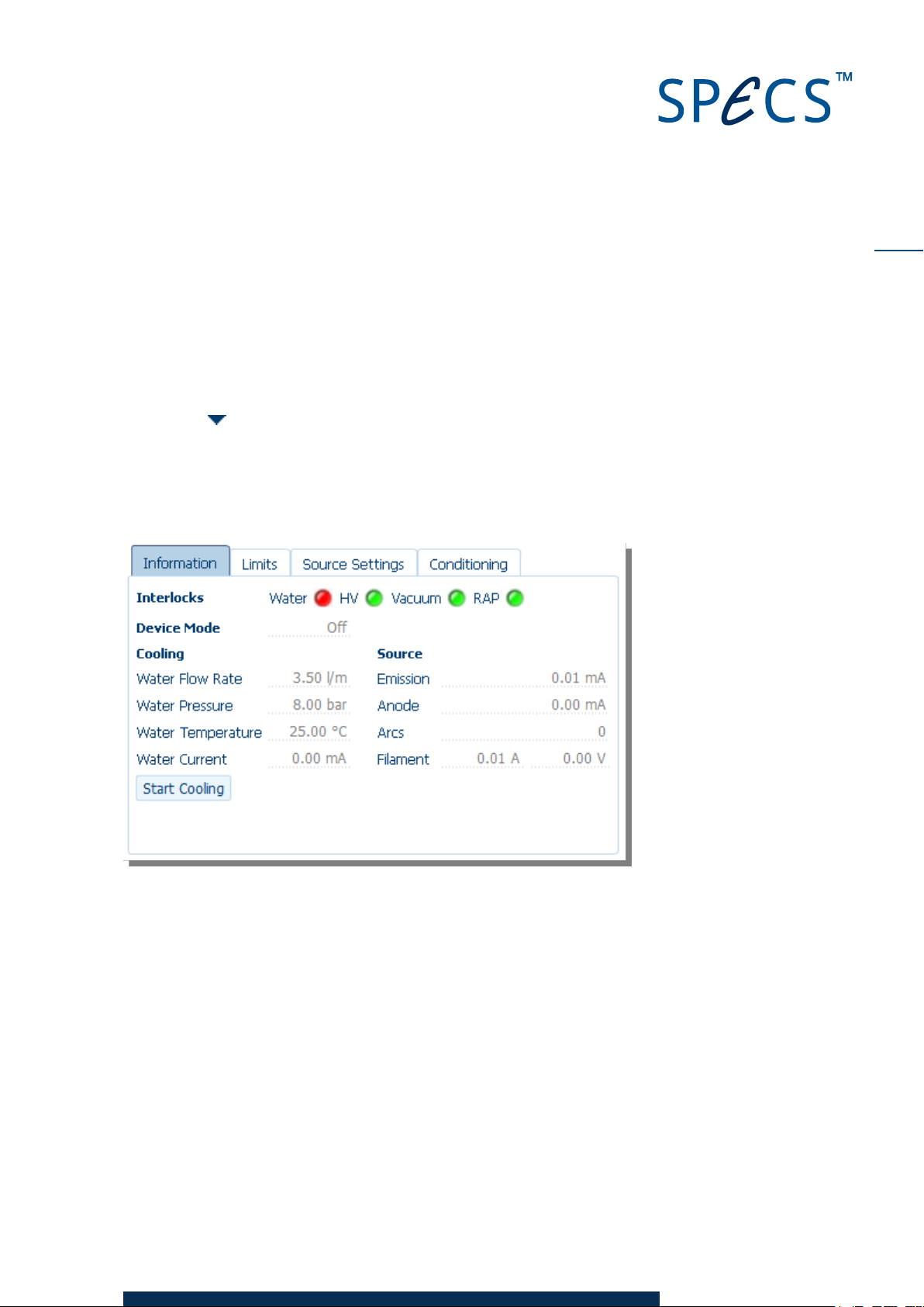
To view the cooling water parameters in SpecsLab Prodigy:
1. Start SpecsLab Prodigy.
2. Go to the Device Controls view. By default, this is open when the application starts and can
be selected by clicking the tab at the top of the Experiment Editor. If it is not open, select
Views/ Device Controls
3. Locate the UXC 1000 device control and click
from the menu bar.
Connect
. There will be a short delay while
SpecsLab Prodigy establishes a connection to the device.
4. Click the button to expand the device control. The status of the water cooling is shown in
the
Information
tab.
Note
The Water interlock indicator is red when the water cooling is switched off.
17
Figure 4: Viewing the cooling water parameters in SpecsLab Prodigy
The
Limits
tab allows you to change the settings for the cooling water. Please see the UXC 1000
manual as well as the SpecsLab Prodigy Online Help for more information.
CCX 70 V1.1 | 29 April 2016
Page 22

18
This page intentionally left blank.
CCX 70 V1.1 | 29 April 2016
Page 23
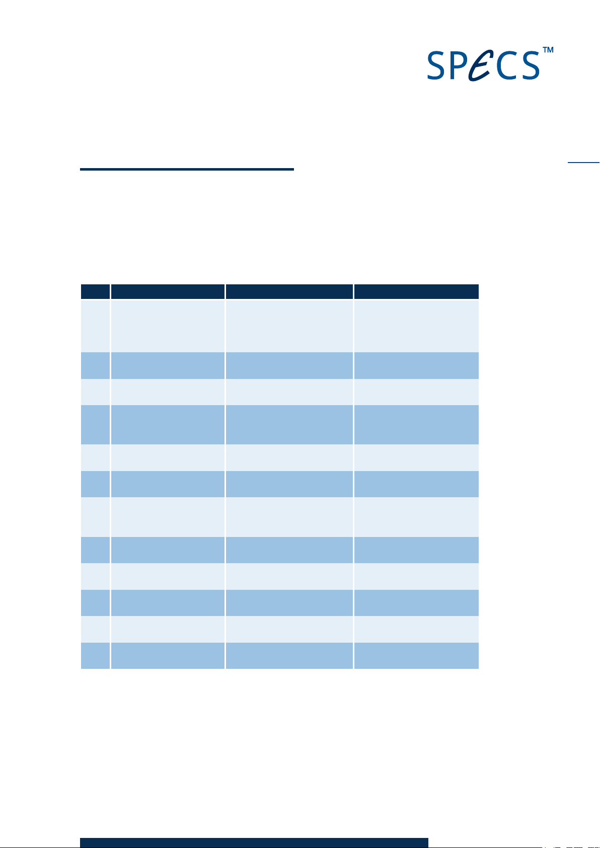
Chapter 5 – Troubleshooting
If a problem occurs during operation, the UXC 1000 will display an error message. The UXC
1000 manual contains a list of all error messages for reference. The table below lists all the
errors related to the water cooling and CCX 70.
Code Message Cause Remedy
1003 "Interlock: Water Interlock
Short Circuit! (1003)"
1004 "CCX-70: Water Interlock
Timeout! (1004)"
1100 "CCX 70: Water Flow too
low! (1100)"
1101 "CCX 70: Water Tem-
perature out of Range!
(1101)"
1102 "CCX 70: Water Pressure
too high! (1102)"
1103 "CCX 70: Water Pressure
too high! (1103)"
1104 "CCX 70: Overload (Short
Circuit)! (1104)"
1105 "CCX 70: Front Door
Open! (1105)"
1106 "CCX 70: Water Leak!
(1106)"
1107 "CCX 70: Communication
Error! (1107)"
1108 "CCX 70: Unknown Error!
(1108)"
2203 "HVC: Water Current too
high! (2203)"
Table 1: U XC 1000 error messages relating to the CCX 70
Water interlock is OK but
water should be OFF.
Water interlock did not turn
to OK within timeout.
Water flow is below limit. Check limits, check water cir-
Water temperature above
upper or below lower limit.
Water pressure above limit. Check limits, check water cir-
Water pressure above limit. Check limits, check water cir-
CCX 70 consumes too much
current, possible short circuit
in cable from UXC to CCX 70.
CCX 70 Front door is open. Close door.
Water leak inside CCX 70. Call service.
Communication problem
between UXC and CCX 70.
Might indicate communication problem.
Water current is too high. Check water.
Check water circuit, cooling,
CCX 70, cable connection
between UXC 1000 and CCX
70.
Check water circuit, cooling,
CCX 70.
cuit, check CCX 70.
Check limits, check cooling.
cuit, check CCX 70.
cuit, check CCX 70.
Check CCX 70 and all cables
and try again, if problem persists, call service.
Check cables.
Check cables.
19
Most of these problems are related to the interlock conditions being satisfied, or to the correct
flow of water in the circuits, as described in more detail in the following sections.
CCX 70 V1.1 | 29 April 2016
Page 24
20
5.1 Wa ter Interl ock Pr obl ems
With first operation after connecting, some air bubbles may pass through the system. These
will cause the interlock to trip. In this case, switch on a few times until all the bubbles have
gone.
The UXC 1000 will report any problems with the water interlock. The Chiller menu shows the
current status of the CCX 70. You should check the following points:
Water flow direction from between the CCX 70 and water supply.
Make sure the service panel on the front panel is closed. There is an interlock switch on
this panel.
Examine the water hoses between the CCX 70 and the source. Make sure there are no
kinks or loose connections.
Also check the temperature of the water. This should be ~20 °C. If it is not within the limits set
in the UXC 1000, check your water supply or chiller unit.
Caution!
Do not defeat the water interlocks. Severe damage to the source will result
during operation and the warranty will be voided.
5.2 Wa ter Fl ow Problems
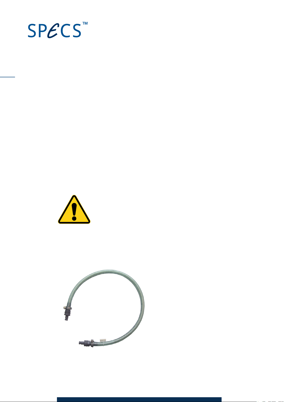
If it appears that the water flow is blocked or significantly reduced, you can use the water
bypass loop supplied with the source to try to locate the bottleneck. Since there are two cooling
circuits in the source, there are two potential places within the source itself where blockages
might exist.
Figure 5:Water bypass loop
CCX 70 V1.1 | 29 April 2016
Page 25
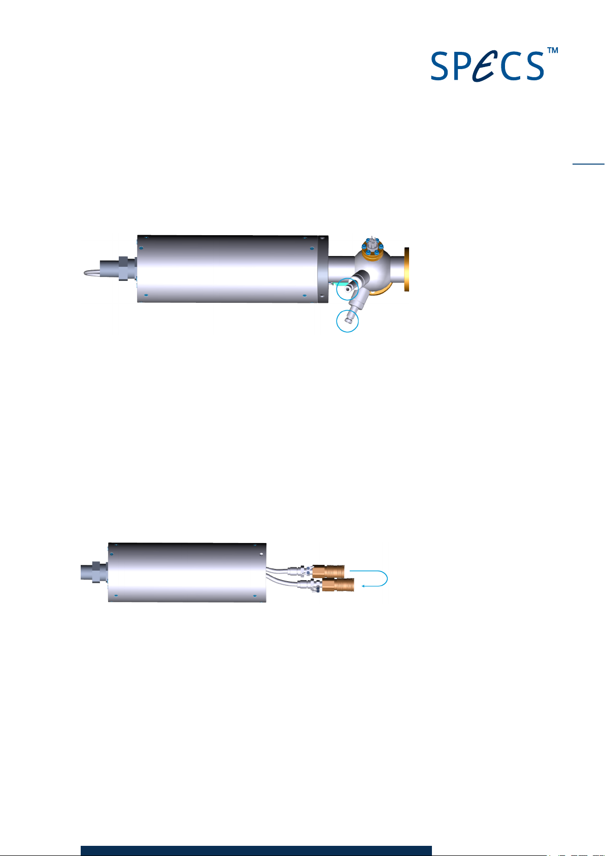
Head coo l ing ci rcuit
To check the head cooling circuit:
1. Remove the two hoses from the head cooling circuit, as indicated in the picture below.
2. Connect the bypass loop between the two hoses.
3. Switch on the water cooling circuit and check the water flow.
An o d e co o l ing ci rcuit
If you have removed the water hoses for the head cooling circuit, as in the description above, fit
them back into place.
To check the anode cooling circuit:
1. Remove the protection cap from the source and detach the connectors from the anode
flange.
2. Fit the bypass hose to the anode connectors in order to complete the circuit, as indicated in
the picture below.
21
3. Switch on the water cooling circuit and check the water flow.
CCX 70 V1.1 | 29 April 2016
Page 26

22
This page intentionally left blank.
CCX 70 V1.1 | 29 April 2016
Page 27
Chapter 6 – Cleaning
Over time, small particles will appear in the water supply due to electrochemical reactions. The
CCX 70 contains internal filters as well as an external filter to the water supply. Over time, con-
taminants will build up on these filters and connections. Clean these parts occasionally to
ensure adequate water flow and to prevent contaminants from damaging the source.
These maintenance steps involve the following tasks:
Removing the internal filters and cleaning them.
Cleaning the anode connections.
Cleaning the external filter.
Checking the condition of the hoses.
These procedures should be performed every 100–200 working hours. Observe the require-
ments and advice contained in Chapter 3 – and check the water quality regularly.
These cleaning operations should be performed approximately every year.
In the event of severe contamination, you will need to chemically clean the cooling system, as
described in "Cleaning the Water Cooling Circuit" on page 26.
23
6.1 Cleanin g the In terna l Fi lters
There are a set of internal filters that collect sediment from the water. A service area on the
front panel of the CCX 70 provides easy access to these filters without it being necessary to
open the case.
Caution!
There is a water leak sensor inside the CCX 70. If any water leaks into the
interior of the unit, it may disable the unit.
Note
The service panel contains an interlock switch that prevents operation when it is open.
To clean the internal filters:
1. Switch off the UXC 1000.
2. Undo the two screws retaining the service area on the front panel and let the panel down
on its hinges.
3. Remove the two cathode socket head cap screws and the two internal particle filters.
CCX 70 V1.1 | 29 April 2016
Page 28
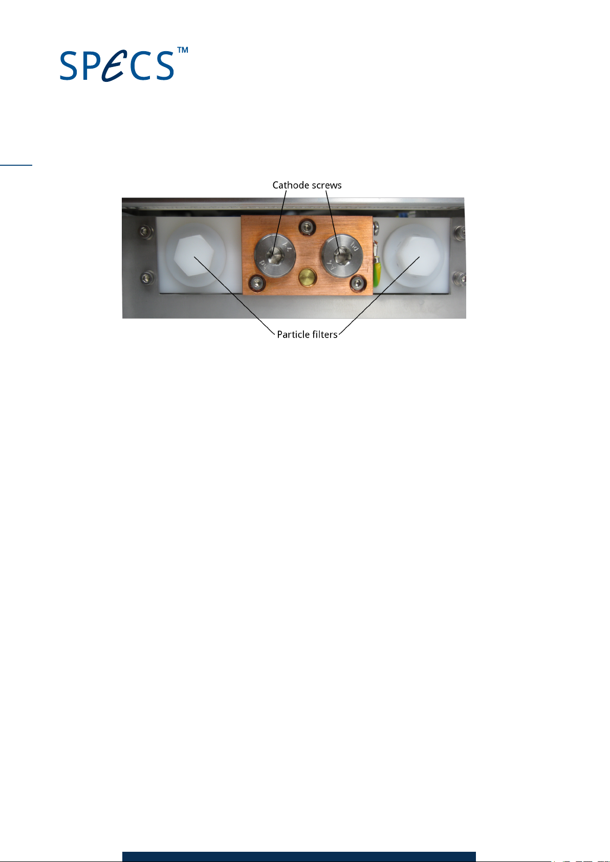
24
Figure 6: Open service area on front panel
4. Clean the following items:
Filters
Cathode screws
Cathode PTFEblock
5. Reassemble the cathode block and close the service area panel.
6. Run the water for a short time, then check for leaks. Remember that this panel is inter-
locked.
6.2 Cleanin g the An ode Con nec ti ons
In addition to the internal filters, contaminants can also build up on the anode water cooling
connections.
Inspect the anode before bakeout or as part of the routine maintenance, whichever is sooner.
Note
A spare set of HVelectrodes is included in the delivery. If you suspect that the anode is leaking
or corroded, replace the electrodes. See the source manual for details of how to change the
anode.
To clean the anode connections:
1. Switch off the source and allow it to cool down.
2. Remove the protection cap from the source (see "Fitting the Protection Cap" on page 7)
3. Remove the quick hose connector.
4. Clean the hose connectors and anode tubes on the source using tissues or cotton wool tips
and water.
CCX 70 V1.1 | 29 April 2016
Page 29
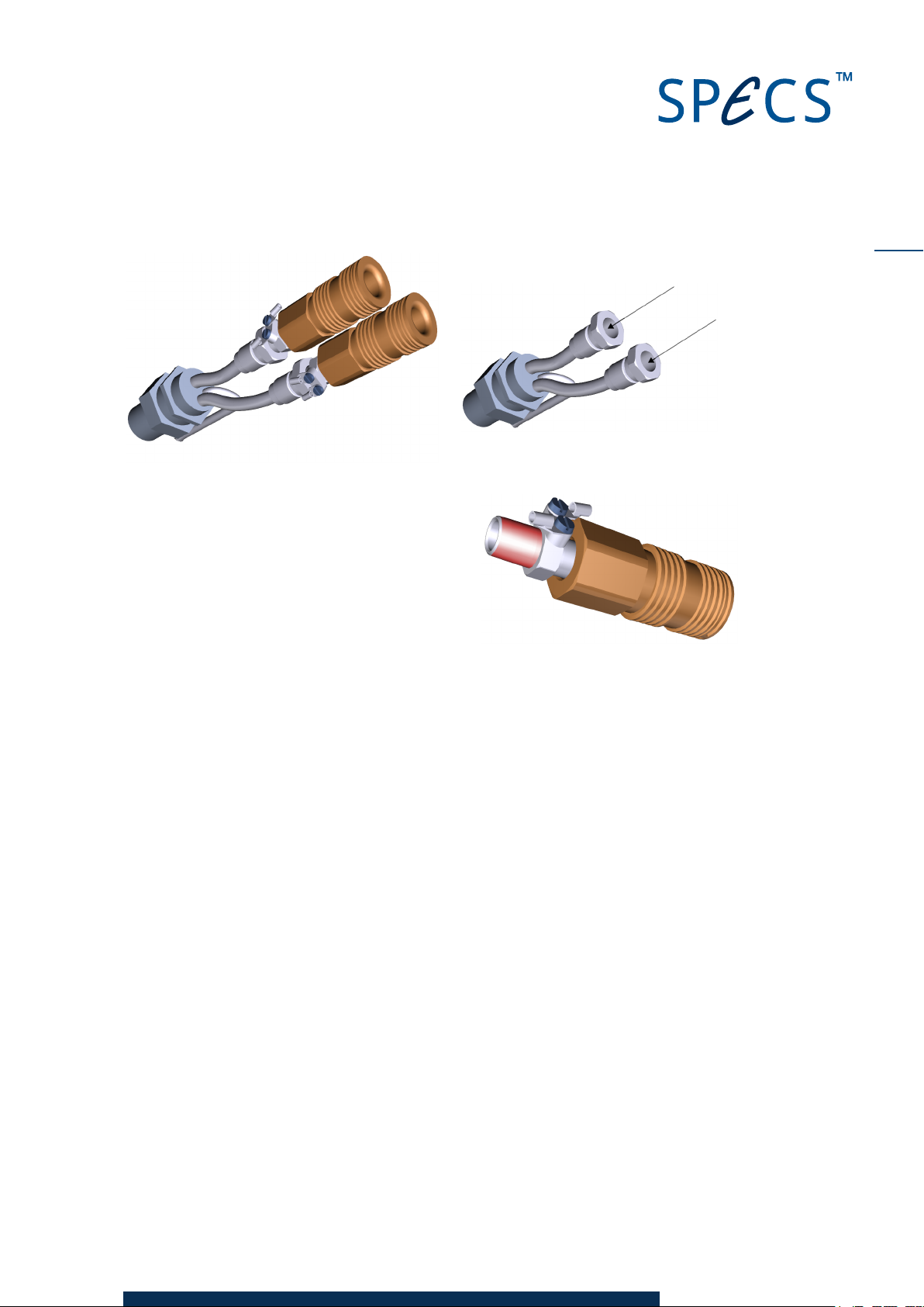
5. Reassemble the connectors. If necessary, wrap
PTFE tape around the connector to ensure a
water-tight seal.
6. After replacing the protection cap, allow water to run through the circuit for a few minutes,
then remove the cap to confirm that the connections are not leaking (i.e. no water drops or
moisture on the connectors).
7. Fit the protection cap. The source is ready for use.
25
6.3 Cleanin g the E xtern al Filter
For safe operation of the flow meter and to avoid blocking or reducing the water flow by
particles, an external particle filter is attached to the water input. This is easy to access and
clean and should also be cleaned as part of the routine maintenance procedure.
Note
If you remove the filter from the hose, observe the flow direction when reconnecting.
To clean the external filter:
1. Switch off the water cooling supply.
2. Unscrew the cover on the blue filter on the water input line.
3. Remove the white filter.
CCX 70 V1.1 | 29 April 2016
Page 30
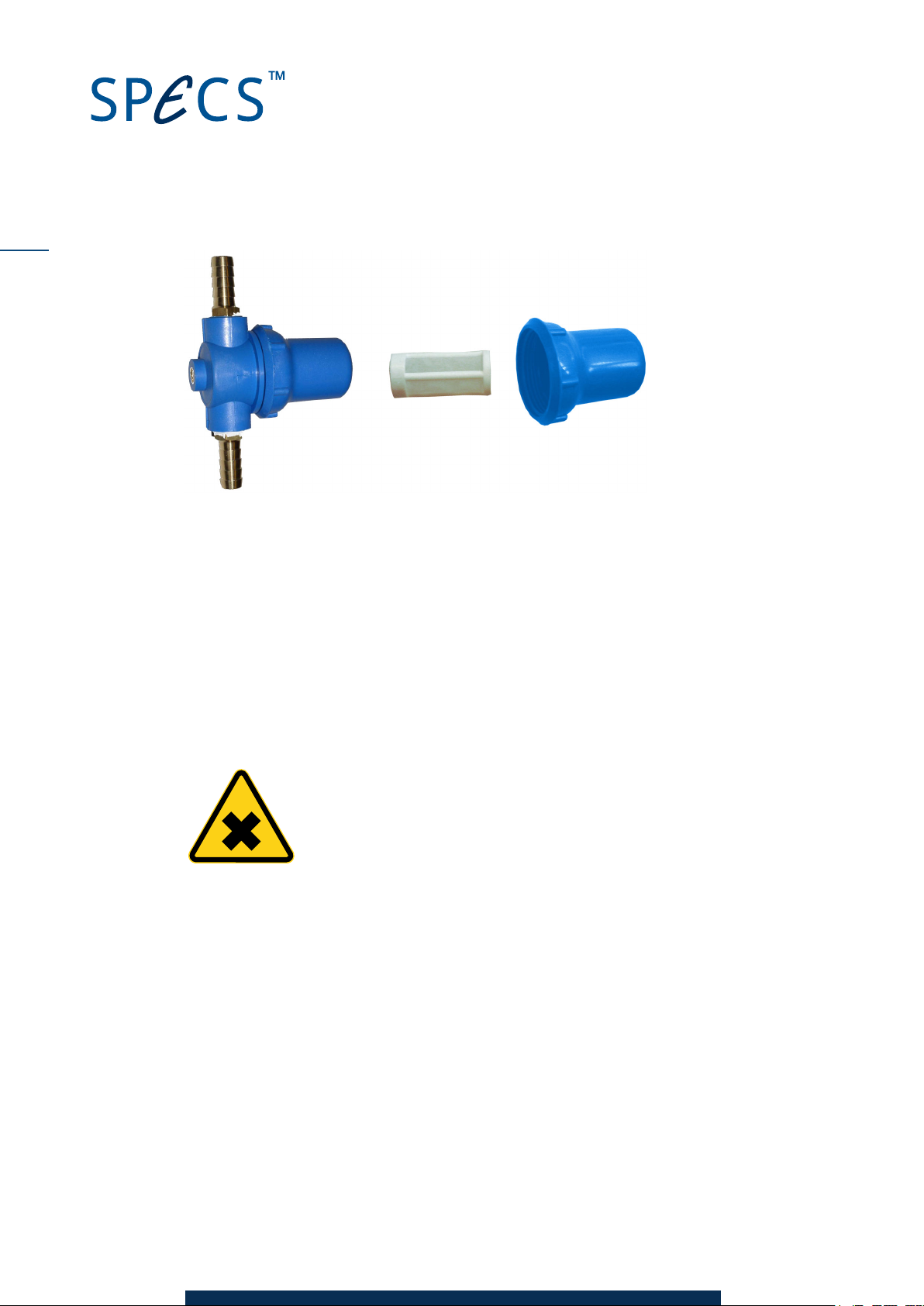
26
Figure 7:Removing the external filter
4. Wash the filter with tap water.
5. Replace the filter and screw the cover back into place.
6.4 Cleanin g the Water Cooli ng C ir cui t
Very long working periods or poor water quality can cause a build up of contamination in the
cooling circuit. These deposits are visible in the tubes inside the CCX 70.
If you have a closed circuit water chiller, you can clean the whole circuit by pumping a citric acid
solution through the system.
Warning—Harmful!
Citric acid (2-hydroxypropane-1,2,3-tricarboxylic acid) is a skin and eye irrit-
ant.
CAS-number 5949-29-1.
To clean the water cooling circuit:
1. Dissolve ~700 g of citric acid in water and add this solution to the water chiller.
2. Switch off the cooling for the water chiller, leaving the water pumps running.
3. Start water flow through the source by selecting the Chiller menu and pressing Start.
4. Allow the citric acid solution to run through the system for 12 hours. During this time, the
water temperature will rise slightly—this is desirable, as it increases the reactivity accord-
ingly.
5. Drain the water chiller and refill it with tap water. Allow the water to run through the source
for five minutes to rinse away the acid.
6. Repeat step 5 twice.
7. Refill the water chiller with distilled or deionized water.
8. Switch on the cooling and pump the water through the source.
CCX 70 V1.1 | 29 April 2016
Page 31

For exceptionally contaminated systems, you might try any or all of the following:
Use a saturated solution of citric acid (~750 g/l of water).
Warm the water with a thermostat up to a temperature of ~50–60 ºC.
Run the citric acid solution through the source for up to 24 hours.
27
CCX 70 V1.1 | 29 April 2016
Page 32

28
This page intentionally left blank.
CCX 70 V1.1 | 29 April 2016
Page 33
Chapter 7 – Technical Details
This chapter contains an overview of the features on the front and rear panels of the CCX 70,
including pin assignments of the electrical connectors. It also contains information about the
internal components and construction of the instrument.
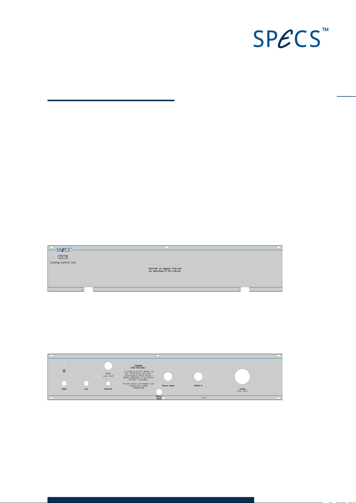
7.1 Fr on t Panel
There is no power switch on the front panel of the CCX 70—power is controlled by the UXC
1000.
The only feature on the front panel is the service area. This is held in place by two screws. The
service area opens on hinges, providing easy access to the cathode filters. The cleaning pro-
cedure is described in "Cleaning the Internal Filters" on page 23. There is a switch fitted to the
panel which acts as an interlock. The power is switched off when the panel is open.
29
Figure 8:Front panel
7.2 Rear Pan el
The rear panel is fitted with all electrical and water connections, as well as a water drain. The
figure and sections below describe the features. Pin assignments of the connectors are also
included.
Figure 9: Rear panel
HV I n
This cable connects to the HVOut on the UXC 1000. It routes the voltage with the anode cooling
water through the Anode conduit.
CCX 70 V1.1 | 29 April 2016
Page 34
30
An o d e
This plastic covered conduit carries the cooling water for the anode as well as the anode
voltage. At the source end of the conduit, there is a protection cap so that no exposed parts of
the source are at high voltage during operation. See "Fitting the Protection Cap" on page 7 for
more information.
Interlo ck
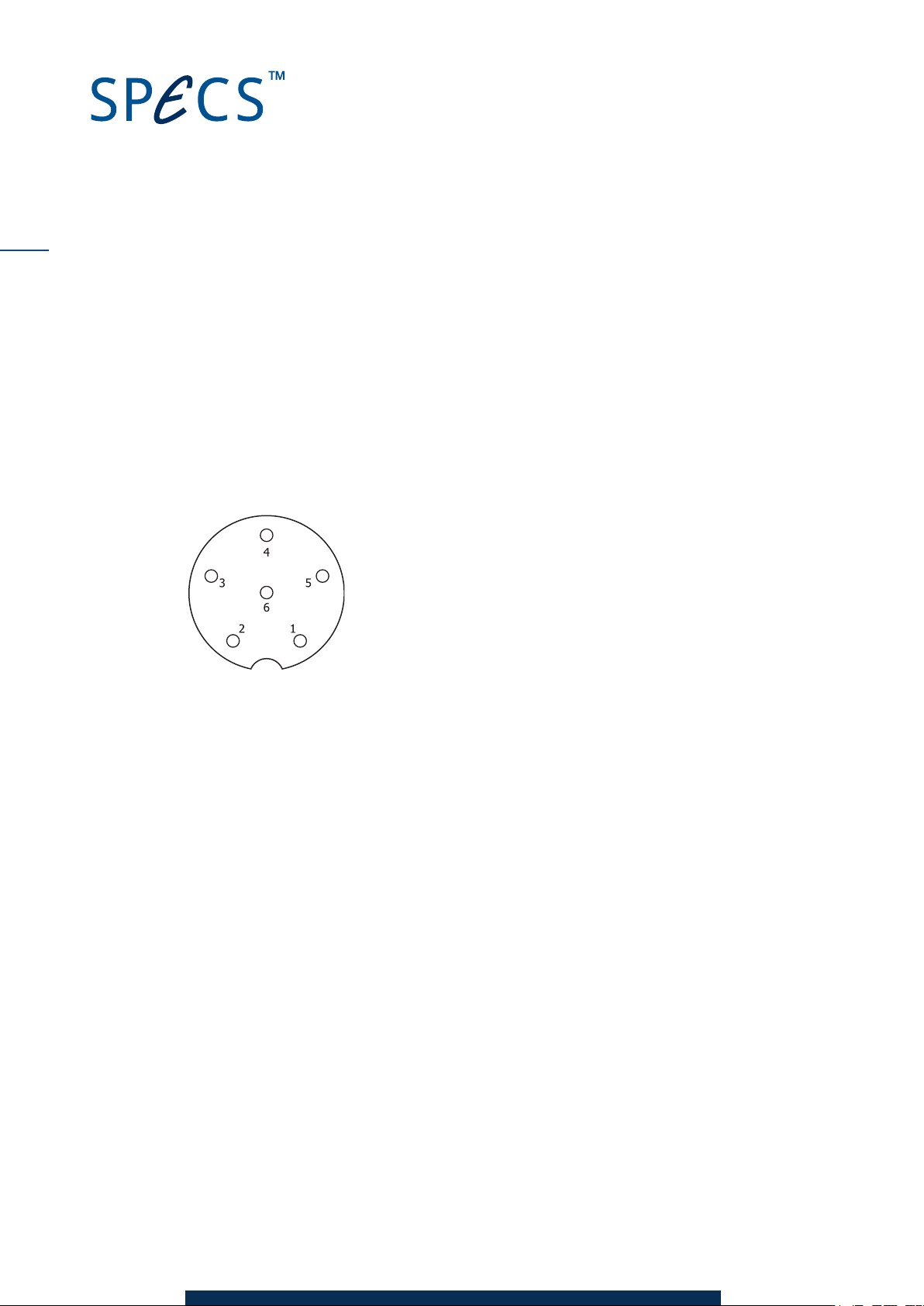
The Interlock connector (6-pin M8) provides power for the CCX 70, as well as carrying the inter-
lock status and the communication interface with the UXC 1000 HVUnit.
Pin Assignment
1 +5 V (interlock signal)
2 Water interlock
3 TXD (transmit control signal)
4 RXD (receive control signal)
5 GND
6 +24 V (power supply for CCX 70)
Figure 10:Water interlock connector pin-out
Chiller
The CCX 70. is able to control a water chiller. The Chiller output provides a 24 V signal that can
switches power to the water chiller. An example of the wiring scheme is shown in "Head Cool-
ing Circuit" on page 8
Link
The Link connector is useful if your system contains two or more CCX 70 units.
It provides a connection between two CCX 70 units and makes sure that only one CCX 70 is able
to control a closed circuit water cooler at any time. If more than one system simultaneously
accesses a cooling circuit, the water pressure will drop, potentially below the pressure required
for operation, causing one or both intruments to switch off.
Figure 11 shows the wiring scheme for two CCX 70 units. Each is connected to its own UXC
1000. The Chiller output on one CCX 70 is then connected to the Link on the other.
CCX 70 V1.1 | 29 April 2016
Page 35
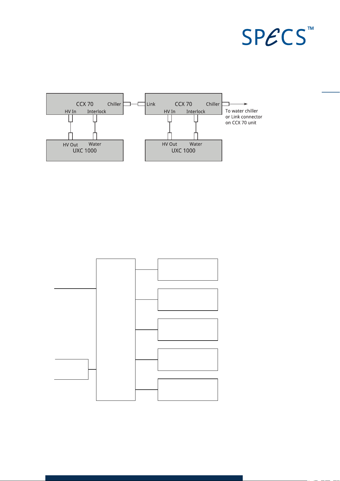
Figure 11: Using the L ink feature
Mainboard
Flowmeter
Pressure sensor
Temperature sensor
Capacitative sensor
Valve
Chiller
Link
HV control
Water interlock
RXD
TXD
ILOCK+
ILOCK–
+24 V
GND
Water co n nectio n s
See "Head Cooling Circuit" on page 8 for instructions of how to connect these connections.
Water drain
This tube is connected to the internal water tank and allows water to escape in the event of an
internal water leak. You should attach a hose which leads away from the electronic racks.
7.3 Block Di agr am
The diagram below shows the components used in the CCX 70.
31
Figure 12: Block diagram
CCX 70 V1.1 | 29 April 2016
Page 36
32
7.4 Interi or Details
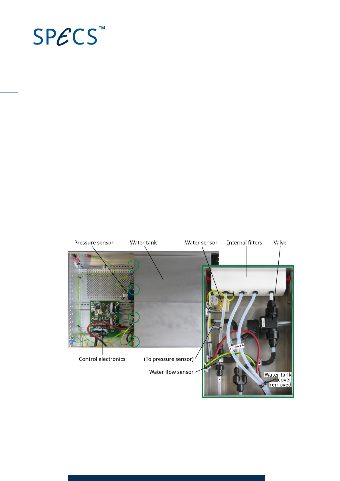
The water connections inside the CCX 70 are contained inside a water tank which prevents
water leakage into the rest of the unit. There is a water sensor on the bottom of the tank that
shuts down the water supply in the event of a leak.
Figure 13 shows the main internal features of the CCX 70. The inset shows the water tank with
the cover removed.
A water drain at the rear allows water to flow out of the unit. You should attach the water drain
to a hose to lead water away from electronics racks.
To open the water tank:
1. Remove the four screws marked with green circles in Figure 13. For most purposes, you
can leave the earthing straps attached. If you need to remove these, remember to replace
them when refitting the covers.
2. Slide the covers away from the edge of the case and lift them away.
Figure 13: Interior of the CCX 70
CCX 70 V1.1 | 29 April 2016
Page 37

7.5 Spec ifi cation s
Table 2 contains a list of general specifications for the CCX 70.
Property Value
Size 19" rack, 3 units height, 360 mm depth.
Weight 14 kg.
Power 24 VDC from UXC 1000 (no mains power).
Water pressure measurement 10 bar.
Water drain 1 cm above tank base.
Operating water pressure 3.5–10 bar.
Particle filter Fitted to input water line—observe correct direction!
Table 2:Specifications
33
CCX 70 V1.1 | 29 April 2016
Page 38

34
This page intentionally left blank.
CCX 70 V1.1 | 29 April 2016
Page 39

Index
35
Algicide
Cleaning
Connections
Electrical
Cooling Unit
Deionized Water
Distilled Water
Drain
External Filter
Filters
Flow Rate
Front Panel
Grounding
A
12
C
23, 25
Operation
Power
Pressure Sensor
O
15
P
33
32
5
5
D
Quality
13
11, 14
5, 32
E
Rack
Rear Panel
Resistance
Return Merchandise Authorization
Q
11
R
5
29
13
1
25
S
F
23, 25
6, 12
Safety
Service Area
Size
2
23
33
23, 29
T
G
5
Tank
Temperature
32
6, 13
H
Hoses
I
Interlock
Service area
Water
M
Mains Supply
CCX 70 V1.1 | 29 April 2016
12
23
12
29
Water
Water Current
Water Drain
Water Pressure
Water Sensor
Weight
X-Rays
Safety
W
15
13
5, 32
15, 29
32
33
X
2
Page 40

36
This page intentionally left blank.
CCX 70 V1.1 | 29 April 2016
 Loading...