

Page 1
/NXP
Quick Start Guide
NX
NVR Series
Version 1.0.1
Page 2

1
Table of Contents
1 Unit .............................................................................................................................................. 3
1.1 Check Unit ......................................................................................................................... 3
1.2 Product Label .................................................................................................................... 3
1.3 Front Panel ........................................................................................................................ 3
1.4 Rear Panel ......................................................................................................................... 4
2 Unit Operation ............................................................................................................................. 6
2.1 Unit Login .......................................................................................................................... 6
2.2 Camera Setup .................................................................................................................... 7
2.3 Schedule Setup .................................................................................................................. 7
2.4 Playback ............................................................................................................................ 8
3 Remote Web Access ..................................................................................................................... 9
Page 3

2
Welcome
Thank you for purchasing this NVR.
This guide is designed to be a quick reference for installing the system.
Please read this guide carefully before installing and operating the unit.
If technical assistance is needed, please contact Speco Technologies Technical Support.
Phone: 1-800-645-5516 option 3
Email: techsupport@specotech.com
Important Safeguards and Warnings
Speco Technologies assumes no liability or responsibility for any fires or electrical shock caused by
improper handling or installation.
Speco Technologies is not liable for any problems caused by unauthorized modifications or attempted
repair, which will void the warranty.
Note: All of the installation and operations here should conform to local electric
safety rules.
Package Contents
Power Cable
CD
Mouse
Ethernet Cable
Quick Start Guide
Unit
Rack mount ears and screws (N16NXP & N32NX only)
Page 4

1 Unit
After unpacking the unit, please check for any visible damage. Then check to make sure that all accessories are
Check that the model number and serial number that’s listed on the label on the unit are the same as what’s
Check that the model number and serial number that’s listed on the label on the unit are the same as w
Figure
1.1 Check Unit
included.
listed on the package label.
1.2 Product Label
listed on the package label.
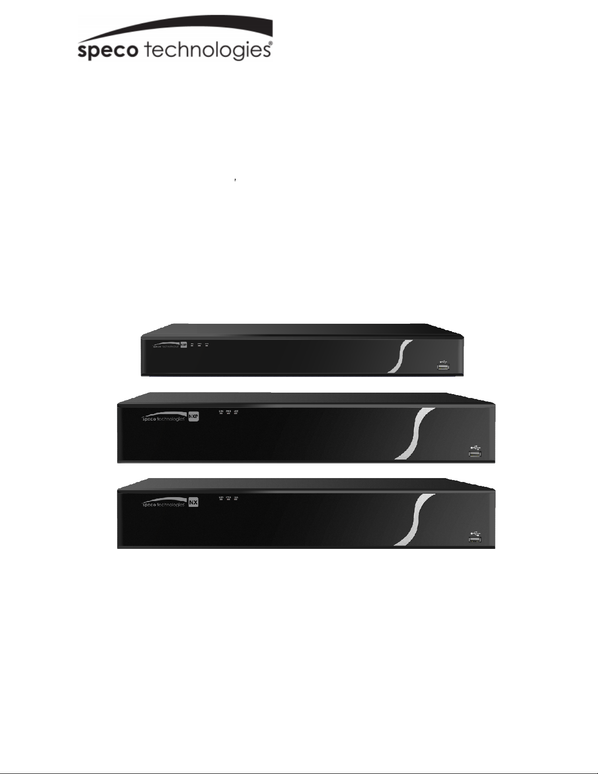
1.3 Front Panel
hat’s
The front panels are shown in
s 1-1 (N32NX), 1-2 (N16NXP), and 1-3 (N8NXP).
Figure1-1
Figure1-2
Figure 1-3
Page 5

4
1.4 Rear Panel
The N8NXP and N16NXP rear panels are shown in Figure 2-2 and Figure 2-2 for reference. The N32NX rear
panel is shown in Figure 2-3
Figure 2-2
Figure 2-2
Figure 2-3
Please refer to the following sheet for detailed information.
Port Name Connection Function
USB3.0 port May be used for a mouse and external storage.
Network port Gigabit Ethernet port. Connect to a network cable.
HDMI HDMI v1.4
VGA VGA output
GND Ground end
MIC IN Audio input port Audio input port for two-way audio. Connect a
MIC OUT Audio output port Audio output port to a speaker
Used for video output to a monitor/display with
HDMI port
Used for video output to a monitor/display with VGA
port
microphone.
Two-way audio output.
Audio output on full screen live view.
Audio output on full screen playback.
Page 6

5
Port Name Connection Function
RS232
(N16NXP/N32NX
only)
A
B
(N16NXP/N32NX
only)
1 – 4 (N8NXP)
1 – 16
(N16NXP/N32NX)
NO Relay output Normally open terminal
C Common terminal
CTRL 12V Relay output /
+12V Power output 12V DC power output. Can be used for devices that
RS232 port Communication port
RS485 Control port for PTZ keyboards, etc
Sensor Input Sensor input ports
Used as the last relay output. Also supplies 12VDC
Power output
power when there is no alarm.
require less than 1A.
Page 7

6
2 Unit Operation
2.1 Unit Login
After the system boots up, the EZ Setup wizard is displayed. See Figure 3-1.
Tips
Check the box to display the EZ Setup wizard window when the system is rebooted.
Figure 3-1
Click Cancel or Next to display the login interface. See Figure 3-2 for the login interface.
Listed below is the default login ID:
Username:
Note:
For security purposes, it is required to create the administrator password on the initial login.
5 incorrect login attempts within 30 minutes will result in a lock on the account. Once the unit is locked, please
wait for 30 minutes before attempting to log in again.
To reset the password, please contact Speco Technologies Technical Support.
admin (administrator, local and remote)
Figure 3-2
Page 8

7
2.2 Camera Setup
The NVR supports plug and play for IP cameras through the built-in PoE ports. In addition, the NVR can scan
for IP cameras that are on the same local network through the EZ Camera feature.
To add cameras, right click and then click on Main menu->Setup->Camera->Site Locate. See Figure 3-3.
Figure 3-3
Click Device Search to find cameras on the local network.
Double click on a camera to add it to the NVR.
2.3 Schedule Setup
Right click and select Main Menu->Setup->Storage->Schedule. See Figure 3-4.
Select the recording mode and then click and drag to set up the recording time period. The system is set to
24hr continuous recording by default.
Page 9

8
Figure 3-4
2.4 Playback
Right click and select Main Menu->Search to bring up the playback interface as shown in Figure 3-6. From this
screen, you can access EZ Search as well as searching by timeframe.
Figure 3-6
Page 10

9
3 Remote Web Access
Open Internet Explorer and enter the NVR’s IP address in the address bar.
Follow the instructions to install the plug-in.
After installation, the login interface is shown as below. See Figure
Please enter the user name and password.
4-1
.
Figure 4-1
For detailed operation information, please refer to the user’s manual.
 Loading...