

Page 1
NLA NVR
User Manual
V1.0
Page 2

Table of Contents
1 Features and Specifications ..................................................................................................................... 12
1.1 Overview ............................................................................................................................................ 12
1.2 Features ............................................................................................................................................. 12
1.3 Specifications .................................................................................................................................... 13
1.3.1 NLA NVR ..................................................................................................................................... 13
2 Front Panel and Rear Panel ..................................................................................................................... 15
2.1 Front Panel ........................................................................................................................................ 15
2.1.1 NLA Series .................................................................................................................................. 15
2.2 Rear Panel ......................................................................................................................................... 15
2.2.1 NLA Series .................................................................................................................................. 15
2.3 Two-Way Audio .................................................................................................................................. 17
2.3.1 Device to PC ............................................................................................................................... 17
2.3.2 PC to Device ............................................................................................................................... 17
2.4 Mouse Operation ............................................................................................................................... 18
3 Device Installation ..................................................................................................................................... 19
3.1 Check Unit ......................................................................................................................................... 19
3.2 Product Label .................................................................................................................................... 19
3.3 Connection ........................................................................................................................................ 19
3.3.1 Example....................................................................................................................................... 19
4 Unit Local Operation ................................................................................................................................. 20
4.1 Startup and Shutdown ....................................................................................................................... 20
1
Page 3

4.1.1 Startup ......................................................................................................................................... 20
4.1.2 Shutdown .................................................................................................................................... 20
4.2 Change/Reset Password ................................................................................................................... 21
4.2.1 Change Password ....................................................................................................................... 21
4.2.2 Reset Password .......................................................................................................................... 22
4.3 EZ Setup ............................................................................................................................................ 23
4.4 Camera .............................................................................................................................................. 26
4.4.1 Camera Setup ............................................................................................................................. 26
4.4.2 Image ........................................................................................................................................... 29
4.4.3 Channel Name ............................................................................................................................ 30
4.4.4 Camera Upgrade ......................................................................................................................... 31
4.4.5 Right Click Menu ......................................................................................................................... 32
4.4.6 Display ......................................................................................................................................... 32
4.4.7 Sequence .................................................................................................................................... 33
4.4.8 PTZ Control ................................................................................................................................. 34
4.4.8.1
4.4.8.2
4.5 Recording .......................................................................................................................................... 40
4.5.1 Stream ......................................................................................................................................... 40
4.5.1.1
4.5.1.2
4.5.2 Schedule ..................................................................................................................................... 42
4.5.2.1
PTZ Function Setup ............................................................................................................ 36
Call PTZ Function ............................................................................................................... 38
Stream ................................................................................................................................. 40
Snapshot ............................................................................................................................. 41
Schedule Recording............................................................................................................ 42
4.5.2.2
Schedule Snapshot ............................................................................................................. 46
2
Page 4

4.5.3 Motion detection .......................................................................................................................... 49
4.5.3.1
4.5.3.2
4.5.4 Alarm Recording/Snapshot ......................................................................................................... 51
4.5.4.1
4.5.4.2
4.5.5 Manual Recording/Snapshot ....................................................................................................... 53
4.5.5.1
4.5.5.2
4.5.6 Holiday Recording ....................................................................................................................... 55
4.6 Playback and Search ........................................................................................................................ 57
4.6.1 Instant Playback .......................................................................................................................... 57
Motion recording ................................................................................................................. 49
Motion Detection Snapshot ................................................................................................. 50
Alarm Recording ................................................................................................................. 51
Alarm Snapshot .................................................................................................................. 52
Manual Recording ............................................................................................................... 53
Manual Snapshot ................................................................................................................ 54
4.6.2 Search Interface .......................................................................................................................... 57
4.6.2.1
4.6.2.2
4.6.3 Snapshot Playback ..................................................................................................................... 64
4.7 Export ................................................................................................................................................ 65
4.7.1 File Backup .................................................................................................................................. 65
4.7.2 Import/Export ............................................................................................................................... 66
4.7.3 Backup Log ................................................................................................................................. 68
4.7.4 USB Device Auto Pop-up ............................................................................................................ 69
4.8 Alarm ................................................................................................................................................. 69
4.8.1 Alarm Detection ........................................................................................................................... 69
File list ................................................................................................................................. 62
Bookmark Pins .................................................................................................................... 62
4.8.1.1
Motion Detection ................................................................................................................. 69
3
Page 5

4.8.1.2
Tampering ........................................................................................................................... 73
4.8.1.3
4.8.2 Notification ................................................................................................................................... 74
4.9 Network .............................................................................................................................................. 76
4.9.1.1
4.9.1.2
4.9.1.3
4.9.1.4
4.9.1.5
4.9.1.6
4.9.2 Network Test ................................................................................................................................ 84
4.9.2.1
Video Loss .......................................................................................................................... 73
TCP/IP ................................................................................................................................. 76
Connection .......................................................................................................................... 77
DDNS .................................................................................................................................. 78
UPnP (EZ Network) ............................................................................................................ 79
Email ................................................................................................................................... 81
FTP ..................................................................................................................................... 82
Network Test ....................................................................................................................... 84
4.9.2.2
4.10 HDD Setup ........................................................................................................................................ 86
4.10.1
4.10.2
4.11 General System Setup ...................................................................................................................... 89
4.11.1
4.11.2
4.12 Device Maintenance and Manager ................................................................................................... 92
4.12.1
4.12.1.1 Version ................................................................................................................................ 92
4.12.1.2 Bitrate .................................................................................................................................. 92
Network Load ...................................................................................................................... 85
Format ..................................................................................................................................... 86
HDD Information ..................................................................................................................... 87
Device Setup ........................................................................................................................... 89
Date and Time ......................................................................................................................... 90
System Info ............................................................................................................................. 92
4.12.1.3 Online User ......................................................................................................................... 93
4
Page 6

4.12.1.4 Remote Device Information ................................................................................................ 94
4.12.1.5 Camera ............................................................................................................................... 95
4.12.1.5.1 Status .............................................................................................................................. 95
4.12.1.5.2 Firmware ......................................................................................................................... 95
4.12.2
Log .......................................................................................................................................... 96
4.12.3
Digital Deterrent ...................................................................................................................... 98
4.12.3.1.1 File Manage .................................................................................................................... 98
4.12.4
Account ................................................................................................................................... 99
4.12.4.1.1 Add User ....................................................................................................................... 100
4.12.4.1.2 Modify user .................................................................................................................... 102
4.12.4.1.3 Change Password ......................................................................................................... 102
4.12.4.1.4 Add/Modify Group ......................................................................................................... 103
4.12.4.1.5 Verification ..................................................................................................................... 104
4.12.5
System Upgrade ................................................................................................................... 105
4.12.5.1 Local Upgrade ................................................................................................................... 105
4.12.6
Factory Default ...................................................................................................................... 106
4.12.7
Maintenance .......................................................................................................................... 107
4.12.8
Logout /Shutdown/Restart .................................................................................................... 107
5 Web Operation ........................................................................................................................................ 108
5.1 General Introduction ........................................................................................................................ 108
5.1.1 Log in ......................................................................................................................................... 108
5.2 LAN Mode ........................................................................................................................................ 110
5.3 Live View ......................................................................................................................................... 112
5.4 PTZ .................................................................................................................................................. 113
5
Page 7

5.5 Image/Alarm-out .............................................................................................................................. 115
5.5.1 Image ......................................................................................................................................... 115
5.6 WAN mode ...................................................................................................................................... 115
5.7 Setup ............................................................................................................................................... 117
5.7.1 Camera ...................................................................................................................................... 117
5.7.1.1
5.7.1.2
5.7.1.3
Camera Setup ................................................................................................................... 117
Stream ............................................................................................................................... 119
5.7.1.2.1 Stream ............................................................................................................................. 119
5.7.1.2.2 Snapshot ......................................................................................................................... 120
5.7.1.2.3 Privacy Mask ................................................................................................................... 120
5.7.1.2.4 Path ................................................................................................................................. 121
Channel Name .................................................................................................................. 121
5.7.1.4
5.7.2 Network ..................................................................................................................................... 123
5.7.2.1
5.7.2.2
5.7.2.3
5.7.2.4
5.7.2.5
5.7.2.6
5.7.2.7
IP Camera Upgrade .......................................................................................................... 122
TCP/IP ............................................................................................................................... 123
Connection ........................................................................................................................ 123
DDNS ................................................................................................................................ 124
Email ................................................................................................................................. 125
UPnP (EZ Network) .......................................................................................................... 125
FTP ................................................................................................................................... 126
HTTPS .............................................................................................................................. 126
5.7.2.7.1 Create Server Certificate ................................................................................................ 127
5.7.2.7.2 Download root certificate ................................................................................................ 128
5.7.2.7.3 View and set HTTPS port ............................................................................................... 130
6
Page 8

5.7.2.7.4 Login ............................................................................................................................... 130
5.7.3 Event ......................................................................................................................................... 131
5.7.3.1
5.7.4 Storage ...................................................................................................................................... 134
5.7.4.1
5.7.4.2
5.7.5 Setup ......................................................................................................................................... 136
5.7.5.1
Video ................................................................................................................................. 131
5.7.3.1.1 Motion Detection ............................................................................................................. 131
5.7.3.1.2 Video Loss ...................................................................................................................... 133
5.7.3.1.3 Tampering ....................................................................................................................... 133
Schedule ........................................................................................................................... 134
Recording Control ............................................................................................................. 135
General ............................................................................................................................. 136
5.7.5.1.1 General ........................................................................................................................... 136
5.7.5.1.2 Date and time .................................................................................................................. 136
5.7.5.1.3 Holiday Setup .................................................................................................................. 137
5.7.5.2
5.7.5.3
5.7.5.4
5.7.5.5
5.7.5.6
5.7.5.7
Account ............................................................................................................................. 137
5.7.5.2.1 User name....................................................................................................................... 137
Display .............................................................................................................................. 140
5.7.5.3.1 Display ............................................................................................................................ 140
5.7.5.3.2 Sequence ........................................................................................................................ 140
Default ............................................................................................................................... 141
Import/Export .................................................................................................................... 141
Maintenance ..................................................................................................................... 141
Upgrade ............................................................................................................................ 142
5.8 System Information.......................................................................................................................... 143
7
Page 9

5.8.1 Version....................................................................................................................................... 143
5.8.2 Log ............................................................................................................................................. 144
5.8.3 Online User ............................................................................................................................... 144
5.9 Playback .......................................................................................................................................... 145
5.9.1 Search Record .......................................................................................................................... 145
5.9.2 File List ...................................................................................................................................... 146
5.9.3 Playback .................................................................................................................................... 147
5.9.4 Download .................................................................................................................................. 147
5.9.5 Additional Download Options .................................................................................................... 148
5.9.5.1
5.9.5.2
5.9.5.3
Download By File .............................................................................................................. 148
Download by Time ............................................................................................................ 149
Watermark ......................................................................................................................... 150
5.10 Log out ............................................................................................................................................. 150
6 Troubleshooting ...................................................................................................................................... 151
8
Page 10

Welcome
Thank you for purchasing this NVR.
Please read this manual carefully before installing and operating the unit.
If technical assistance is needed, please contact Speco Technologies Technical Support.
Phone: 1-800-645-5516 option 3
Email: techsupport@specotech.com
9
Page 11

Important Safeguards and Warnings
1
....
Electrical safety
All installation and operation here should conform to local electrical safety codes.
The product must be grounded to reduce the risk of electric shock.
Speco Technologies assumes no liability or responsibility for all the fires or electric shock caused by improper
handling or installation.
2
....
Transportation security
Heavy stress, violent vibration or water splash are not allowed during transportation, storage and installation.
3
....
Installation
Keep upwards. Handle with care.
Do not apply power to the NVR before completing installation.
Do not place objects on the NVR.
4
....
Qualified personnel
All the examination and repair work should be done by the qualified service engineers.
Speco Technologies is not liable for any problems caused by unauthorized modifications or attempted repair.
5
....
Environment
The product should be installed in a cool, dry place away from direct sunlight, inflammable, explosive
substances and etc.
6. Accessories
Be sure to use the included accessories only.
Before installation, please open the package and check that all components are included.
10
Page 12

Contact the supplier immediately if something is broken or missing in the package.
7. Lithium battery
Improper battery use may result in fire, explosion, or personal injury.
When replacing the battery, please make sure to use the same exact model.
CAUTION
RISK OF EXPLOSION IF BATTERY IS REPLACED BY AN INCORRECT TYPE.
DISPOSE OF USED BATTERIES ACCORDING TO LOCAL LAWS.
Before operation, please read the following instructions carefully.
Keep away from extreme hot places and sources and avoid direct sunlight
Keep away from extreme humid place
Avoid violent vibration
Do not put other devices on the top of the NVR
Be installed in well ventilated place; do not block the vent
11
Page 13

1 Features and Specifications
•
•
•
•
1.1 Overview
The NLA NVR supports live view, recording and playback, and remote management and control of IP
cameras.
The NLA supports plug and play for Speco’s IP cameras. If a camera is connected to one of the PoE ports
that are built into the back of the NVR, it will auto populate on the designated channel without any additional
setup. Once the unit is set up, it can be accessed over the network through: 1) a web browser for quick
viewing, playback, and setup and 2) SecureGuard® VMS, which provides a robust solution for viewing
multiple devices simultaneously and redundancy.
1.2 Features
Viewing layout options: 1x1, 2x2, 3x3
Live View
Playback
User
Management
• HDMI and VGA outputs for monitors
• PTZ control interface
• Swappable channel tiles in real time
Record up to 8MP (4K) on every channel at 30fps max
• Instant playback for any channel
• Supports various playback modes: slow play, fast play, backward play
and frame by frame play.
• EZ Search (thumbnail based search)
• Export clips on USB flash drives and hard drives
Customizable groups with access for individual features
• Assign users to different groups
• Up to 128 user accounts supported
Record
Alarm
Upgrade
• Supports video and snapshot storage
• Record in continuous, motion, and sensor modes
• Trigger recording through motion, sensor, and tampering.
• Events can also trigger a relay alarm device and Digital Deterrent®
• Alerts can be also sent via email.
Supports local and remote upgrades via web browser
12
Page 14

1.3 Specifications
1.3.1 NLA NVR
Model N4NLA N8NLA
System System
Resources
OS
Interface
Decode Compression
Decode
Capability
(local viewing)
Video Input
Output
Split View
Audio Input
Output
4 connections. Total camera
bandwidth of 80Mbps.
Embedded Linux real-time operation system
Local GUI / Web Viewer
H.265 / H.264
Up to 8 channels, 720p @ 30fps
Up to 4 channels, 1080p @ 30fps
1 channel, 8MP @ 30fps
4 channels, network video 8 channels, network video
1 HDMI, 1 VGA
1 RCA input
1 RCA output
8 connections. Total camera
bandwidth of 80Mbps.
1/4/8
Compression
Alarm Input
Output
Function Storage
Port and
Indicator
RS232 Port
RS485 Port
USB Port
Network
Connection
PoE Ports
Indicator Light
G.711a
N/A
N/A
1 internal HDD slot, up to 6TB supported
N/A
N/A
2 USB 2.0 ports
1 10/100/1000Base-T Ethernet port
4 8
Network / Power / HDD status indicators
13
Page 15

Model N4NLA N8NLA
General
Power
Operating
Temperature
Operating
Humidity
Dimensions
(WxHxL)
Weight
48VDC, 1.25A; 50W PoE budget 48VDC, 2A; 80W PoE budget
14°F ~ 131°F
10℅~90℅ RH
10.2” x 1.8” x 8.7”
3 lbs
14
Page 16
2 Front Panel and Rear Panel
2.1 Front Panel
2.1.1 NLA Series
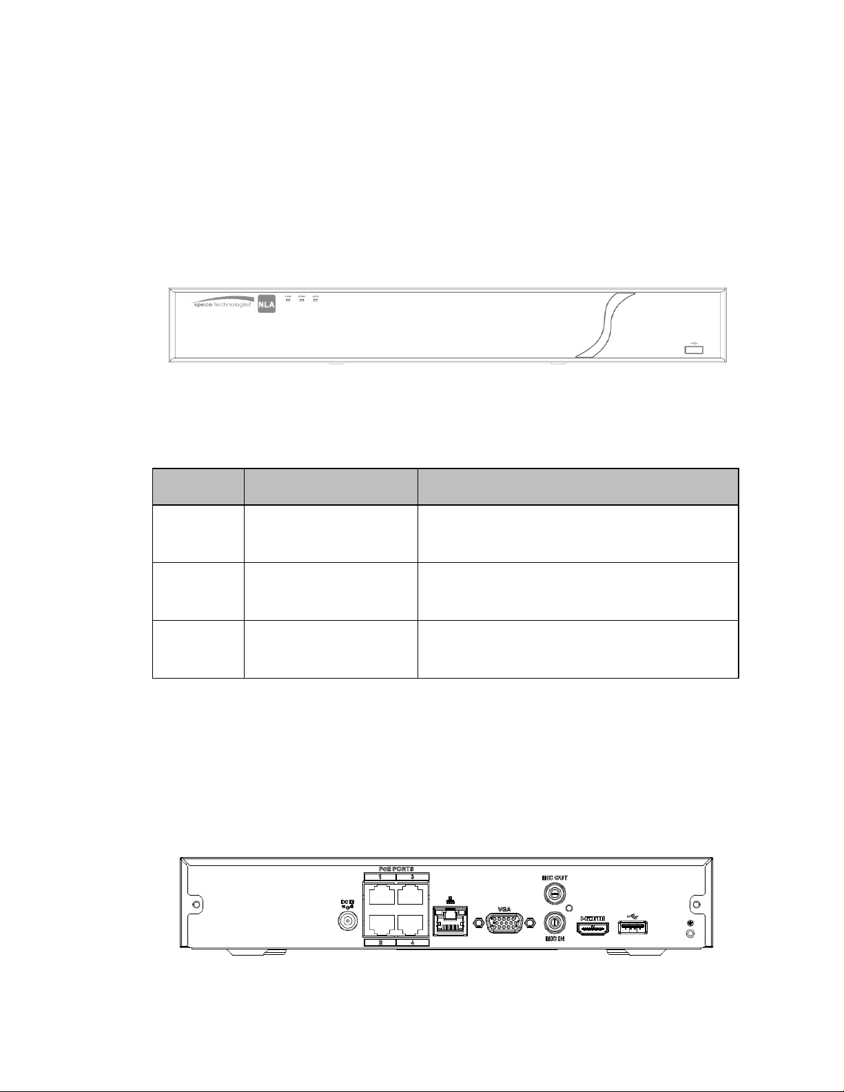
The NLA front panel is shown below. See Figure 2-1.
Figure 2-1
Please refer to the following sheet for detailed information.
Icon
LAN
PWR
HDD
Name Function
Network status indicator
Power indicator
HDD status indicator
Blue indicator is on when connected to a
network
Blue indicator is on when power is operating
normally
Blue indicator is on when the hard drive is
operating normally
2.2 Rear Panel
2.2.1 NLA Series
The 4ch unit’s rear panel is shown below in Figure 2-2.
Figure 2-2
15
Page 17
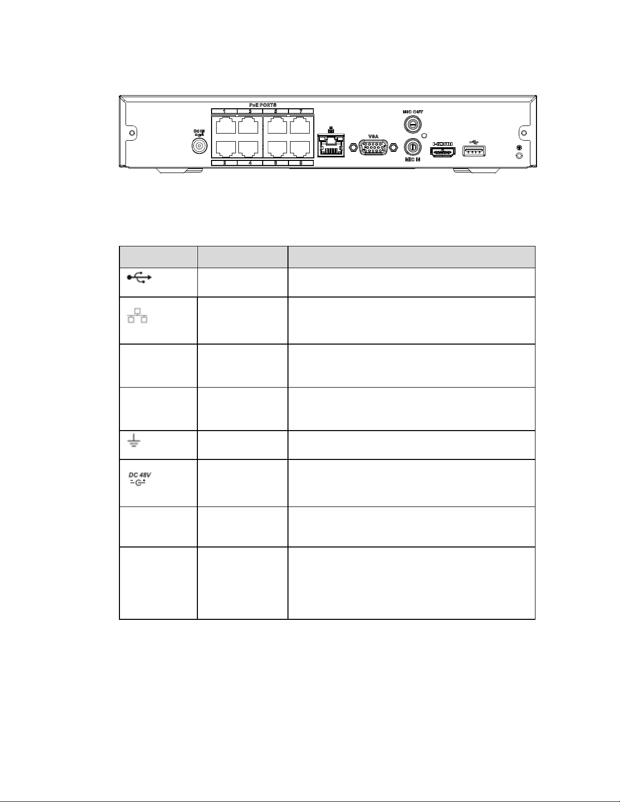
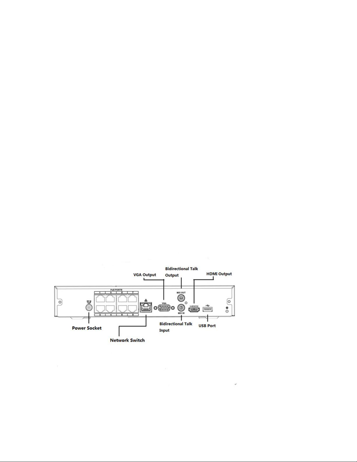
The 8ch unit’s rear panel is shown below in Figure 2-3.
Figure 2-3
Please refer to the following sheet for detailed information.
Port Name Connection Function
USB2.0 port May be used for a mouse and external storage.
Gigabit Ethernet port. Connect to a network
HDMI
Network port
cable.
Used for video output to a monitor/display with
HDMI v1.4
HDMI port
VGA
VGA output
Used for video output to a monitor/display with
VGA port
GND Ground end
Power input
port
Input DC 48V/2A.
MIC IN Audio input port Audio input port for two-way audio. Connect a
microphone.
MIC OUT Audio output
port
Audio output port to a speaker
Two-way audio output.
Audio output on full screen live view.
Audio output on full screen playback.
16
Page 18
2.3 Two-Way Audio
2.3.1 Device to PC
Device Connection
Connect a microphone to the input port located on the rear panel of the NVR. Then connect a speaker to the
audio output port on the PC.
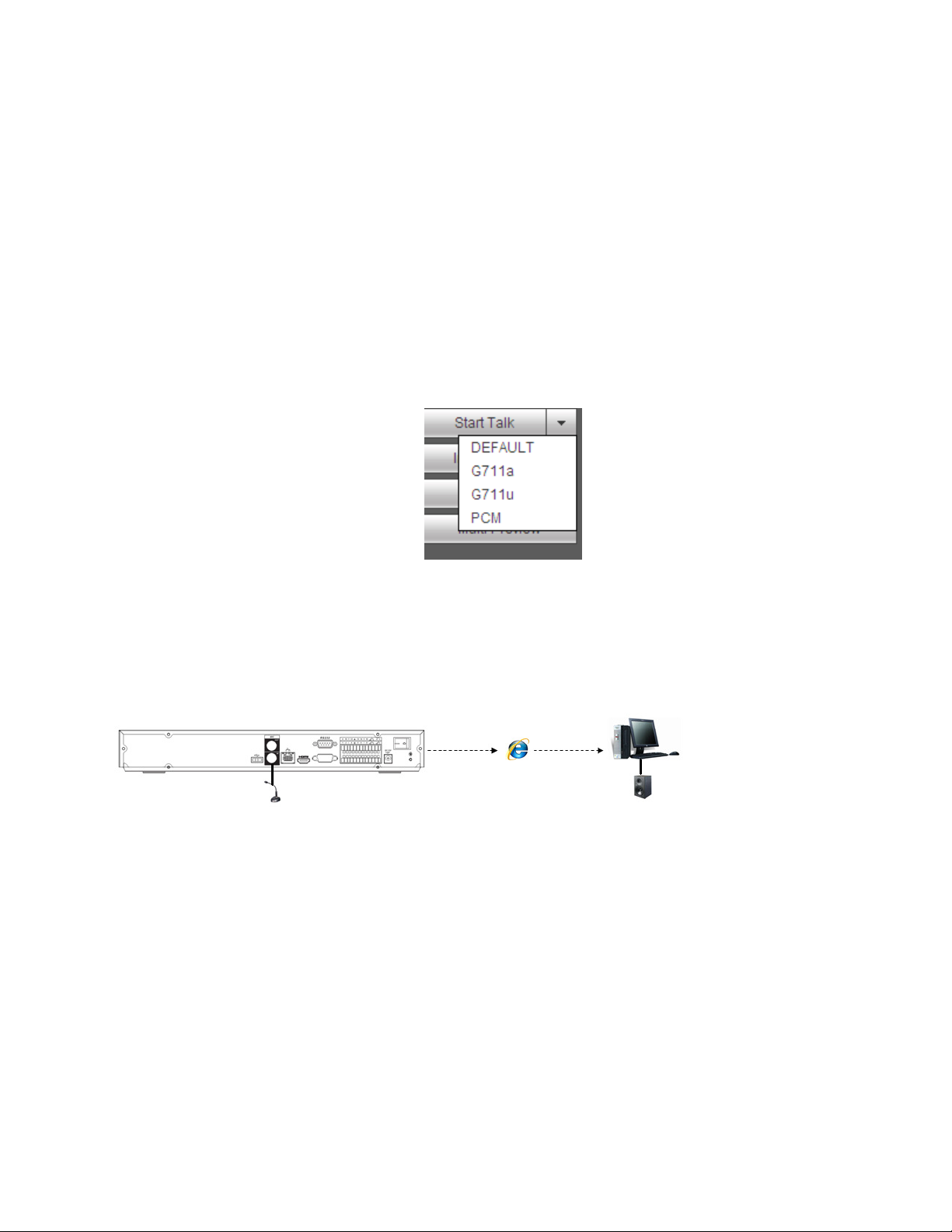
Log into the web viewer to enable two-way audio:
After logging in, look in the left menu panel at the bottom. See Figure 2-4.
Figure 2-4
Audio
See Figure 2-5.
Figure 2-5
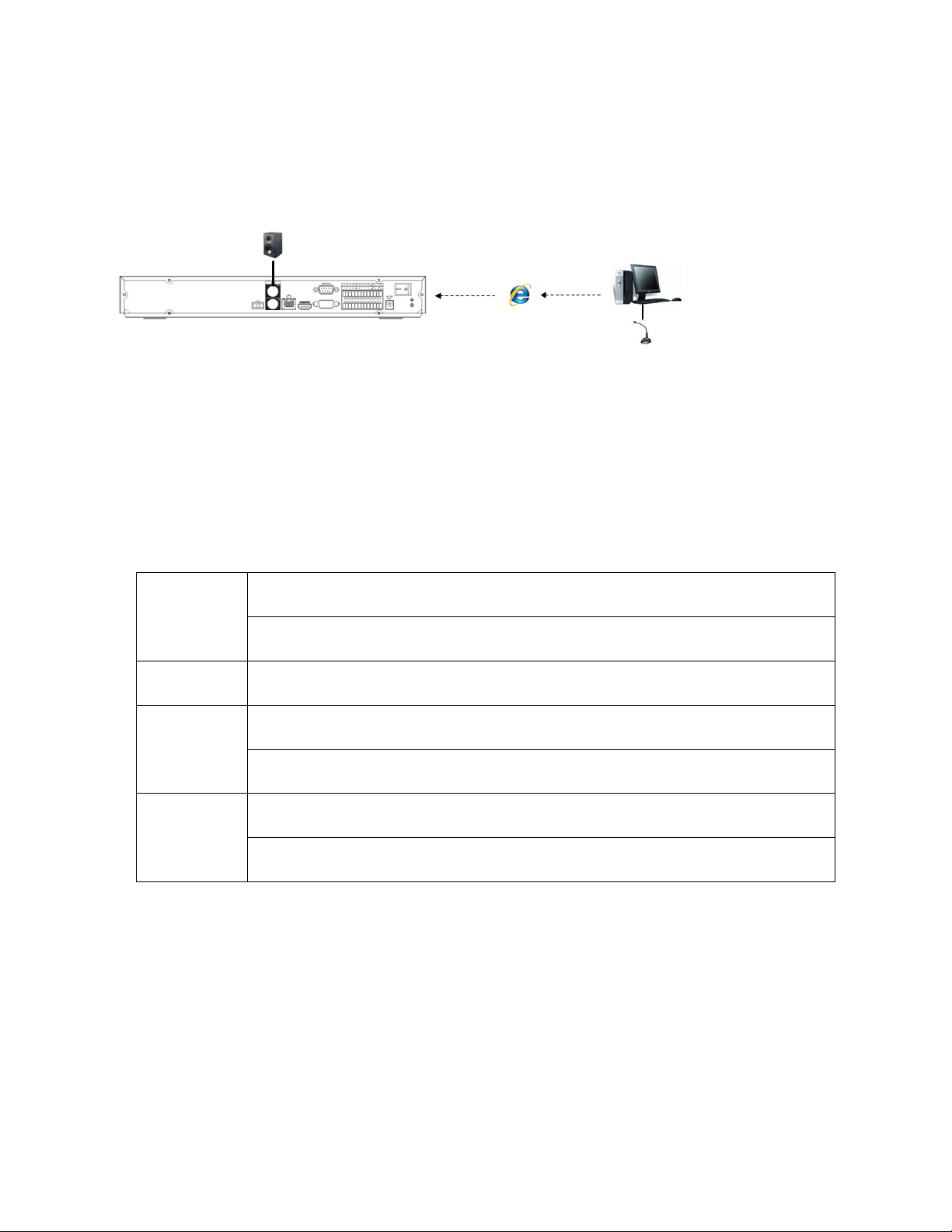
2.3.2 PC to Device
Device Connection
Connect a microphone to the audio input port on the PC and then connect a speaker to the output port on the
rear panel of the NVR.
Log into the web viewer to enable two-way audio.
Please refer to the diagram above (Figure 2-4) to enable this option.
17
Page 19
Audio
See Figure 2-6.
Figure 2-6
2.4 Mouse Operation
Please refer to the following table for mouse operation instructions.
Left Click Menu item selection
Use for on-screen keyboard
Double Click In live view, double click to go from split screen to a full screen and back
Right click Brings up menu options in live view
Exit current menu without saving when in setup
Drag mouse Select motion detection zone
Select privacy mask zone
18
Page 20
3 Device Installation
Note: All of the installation and operations here should conform to local electric safety rules.
3.1 Check Unit
After unpacking the unit, please check for any visible damage. Then check to make sure that all accessories
are included.
3.2 Product Label
Check that the model number and serial number that’s listed on the label on the unit are the same as what’s
listed on the package label.
3.3 Connection
3.3.1 Example
Please refer to Figure 3-1 for a connection example.
The 8-channel unit is shown below.
Figure 3-1
19
Page 21
4 Unit Local Operation
4.1 Startup and Shutdown
4.1.1 Startup
Caution
Before powering up the unit, please make sure:
Connect the NVR to the power adapter first and then connect the power adapter to the power
outlet.
Please follow the steps listed below to start the device.
Connect the device to the monitor and then connect a mouse.
Connect power.
The system will be in split screen mode by default upon startup.
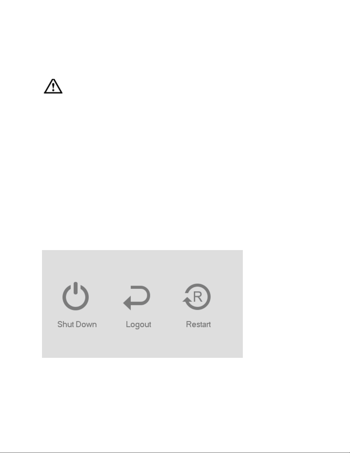
4.1.2 Shutdown
Note
Do not unplug the power adapter when the device is running (especially when it is recording).
The proper way to shut down the unit is:
Main Menu->Shutdown
Click OK.
20
Page 22
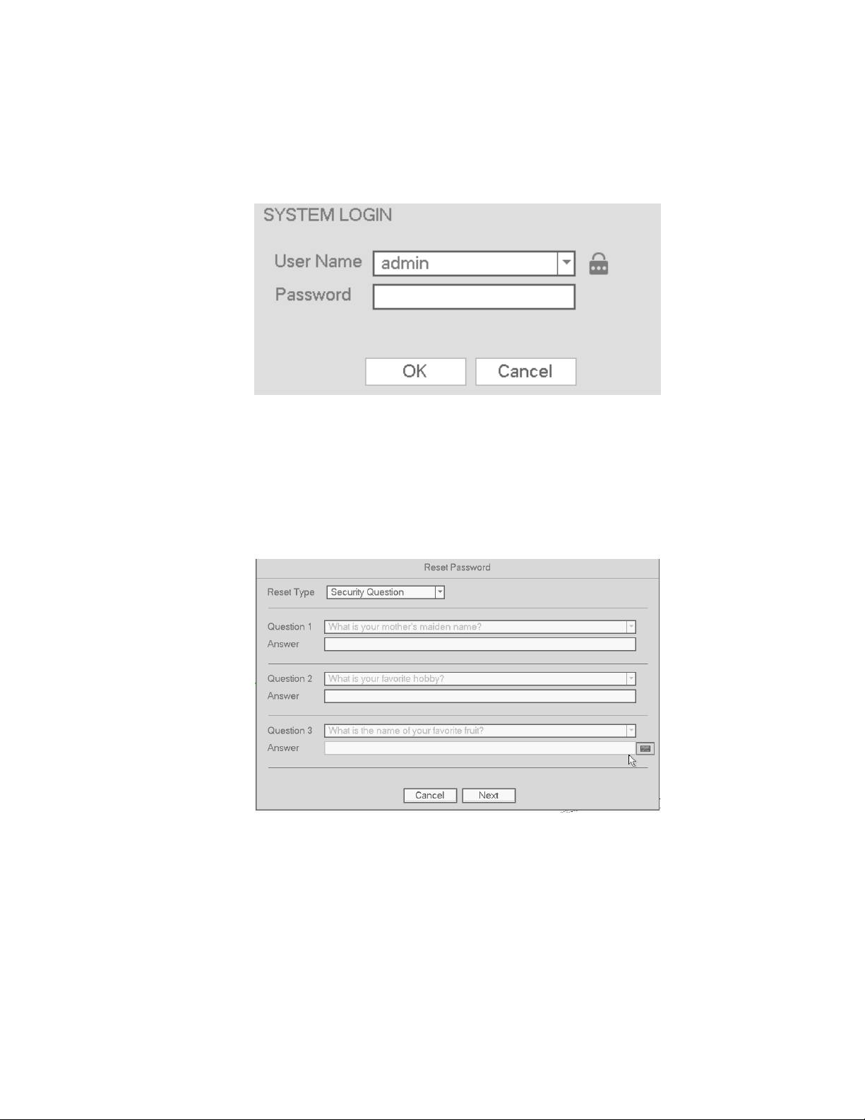
4.2 Change/Reset Password
4.2.1 Change Password
Listed below is the default login ID:
Username: admin (administrator, local and remote)
Note:
For security purposes, it is required to create the administrator password on the initial login.
5 incorrect login attempts within 30 minutes will result in a lock on the account. Once the unit is locked,
please wait for 30 minutes before attempting to log in again.
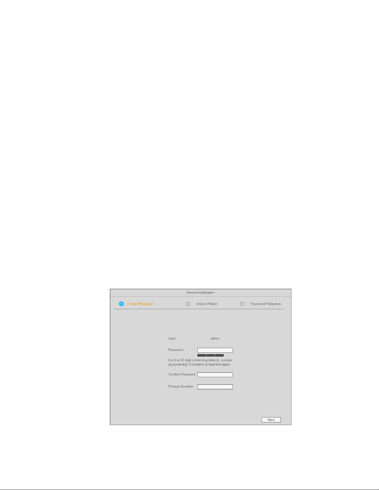
See below for the password change screen.
Create an 8-digit password, consisting of letters and numbers. As a backup, an unlock pattern can be
created.
Security questions can be set here to reset the password in case it is forgotten. Three security questions
must be set. These questions must be answered correctly when resetting the password.
For more information, please refer to section 4.2.2.
Figure 4-1
21
Page 23
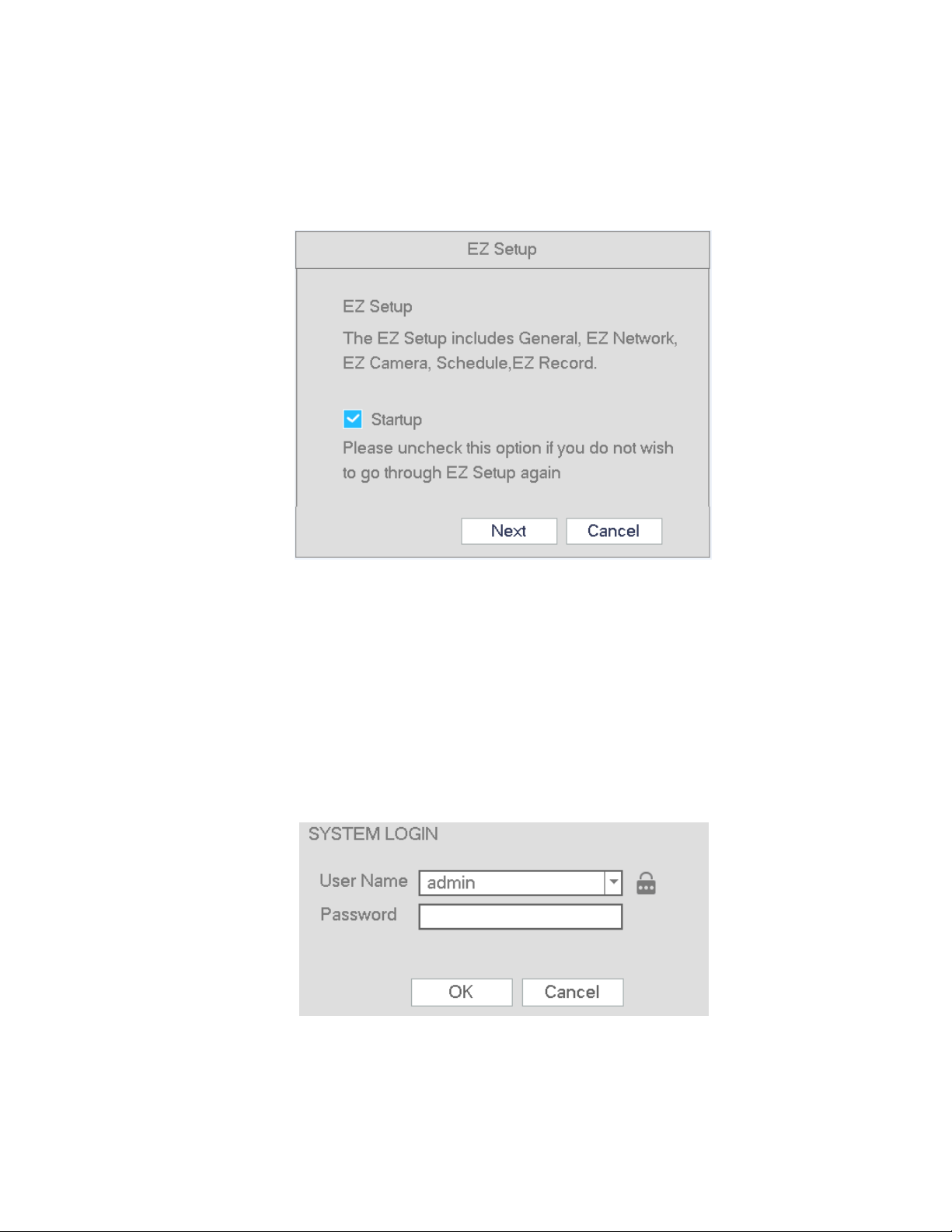
4.2.2 Reset Password
If the password has been forgotten, answer the security questions set in section 4.2.1 to reset the password.
Figure 4-2
The following dialogue box will pop up. Please answer the security questions and then enter Next. See
Figure 4-3.
.
Figure 4-3
22
Page 24
4.3 EZ Setup
After the NVR successfully boots up, the prompt for EZ Setup will pop up. To prevent EZ Setup from running
again on the next reboot, uncheck the Startup box before selecting Next or Cancel.
Figure 4-4
Click Next or Cancel button. See Figure 4-4
The system consists of two accounts:
Username: admin. Password: admin. (administrator, local and network)
Username: default. Password: default (hidden user). Hidden user “default” is for system interior use
only and can not be deleted. When there is no login user, hidden user “default” will automatically login.
Figure 4-5
Click the OK button to go to the Setup Interface. See Figure 4-6.
23
Page 25
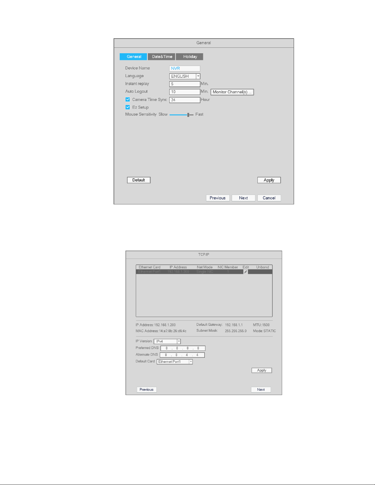
Figure 4-6
Click the Next button to go the to network interface. See Figure 4-7.
Figure 4-7
After configuring, network, DDNS, and UPnP settings, click the Next button to go to the Site Locate tab. See
Figure 4-8.
24
Page 26
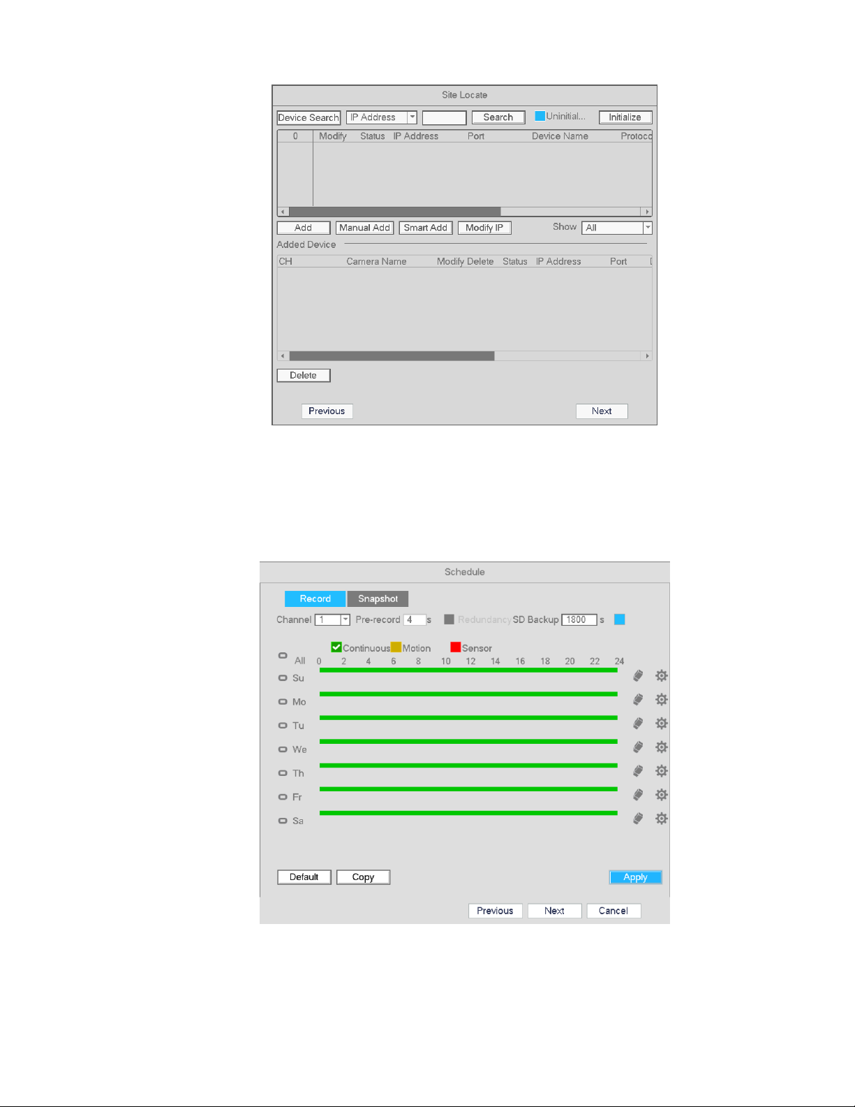
Figure 4-8
Click the Next button to go to the Schedule interface/EZ Record. See Figure 4-9.
For detailed information, please refer to section 4.5.2.
Figure 4-9
25
Page 27
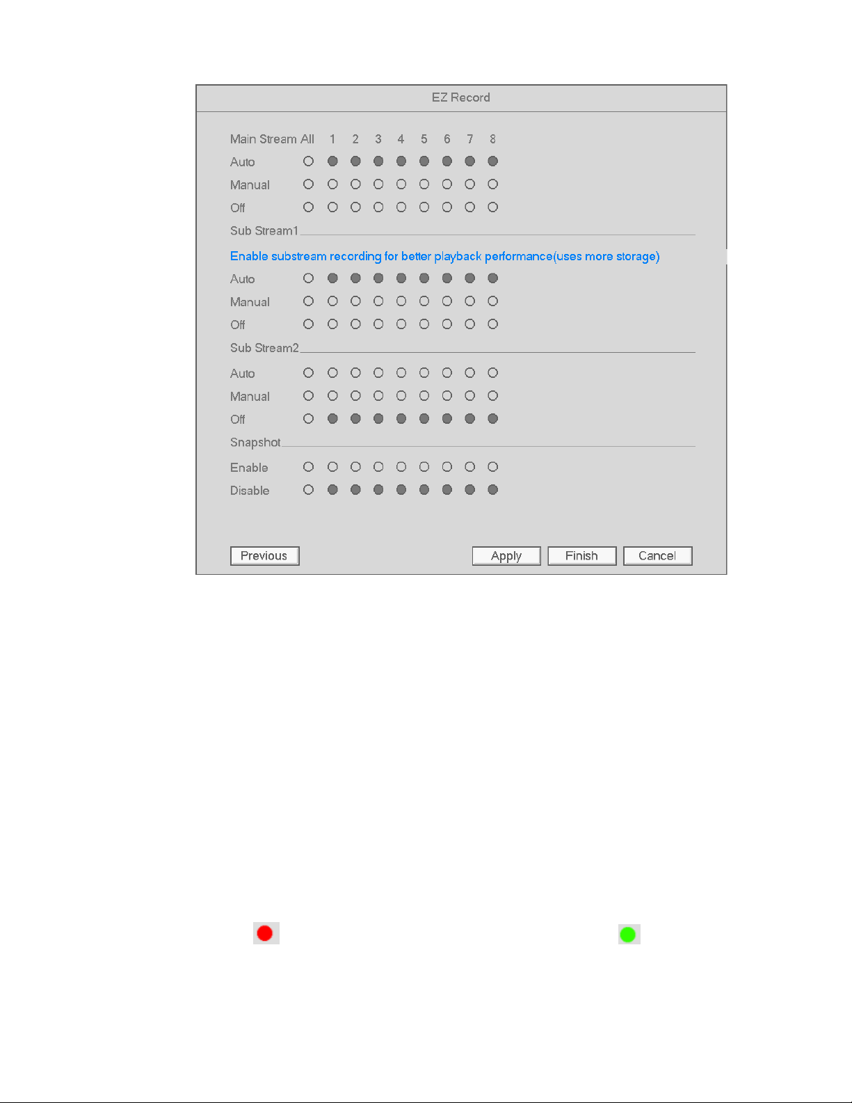
Figure 4-10
4.4 Camera
4.4.1 Camera Setup
Note: For Speco’s IP cameras, the built-in PoE ports support plug and play. In order to this feature to work,
the IP camera’s user ID and password must be kept at the default values, which are admin and 1234,
respectively.
Go to Main menu->Setup->Camera->Camera to open the camera setup interface.
Device search: Click the button to search for all network cameras in the same network segment.
Status: Red circle ( ) means current channel has no video, green circle ( ) means current channel
has video.
26
Page 28
IP address: Displays the network camera IP address.
Port: Indicates the connection port of the IP camera. If the camera is connected to a PoE port on the
NVR, the port number will be indicated.
Add/Delete: Click to remove a camera from a channel. Click “Add” to add a device to the NVR.
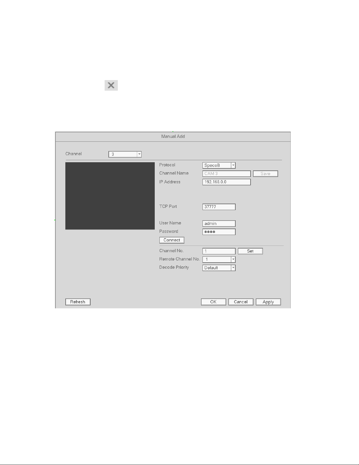
Manual Add: Click the Manual Add button to manually enter camera information and assign it to a
channel. The interface is shown below:
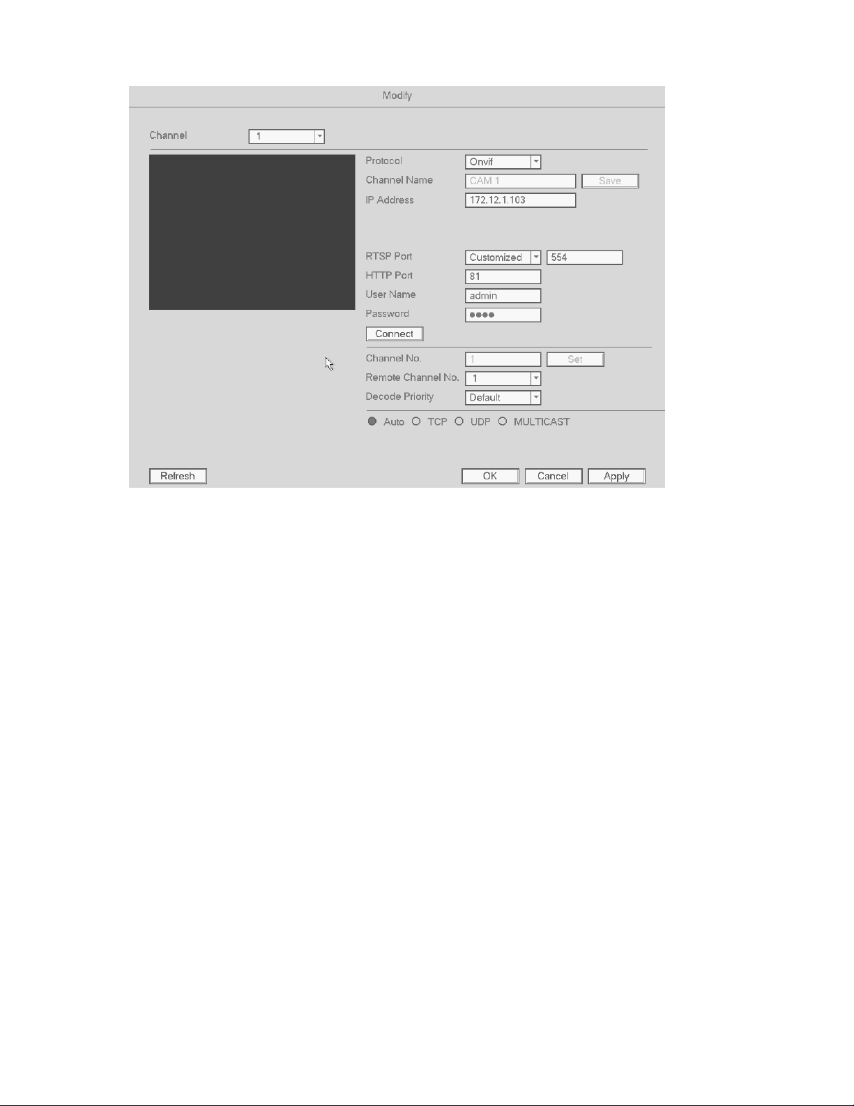
Modify: Click the modify icon for a channel to edit the camera’s information. See below.
27
Page 29
Channel: Change assigned channel.
Protocol: Select protocol from the dropdown list. For Speco A and Speco B, the applicable protocol will
be chosen automatically. Note that for Customized, the RTSP stream URL must be entered for the main
and sub streams.
Channel Name: Enter the nickname of the channel.
RTSP/HTTP port: Enter the correct port values for the camera. If the ports have not been changed on
the camera, the default values are 554 and 80 respectively for almost all camera models.
User name/Password: Enter user name and password of the camera. The default user name is admin
and the default password is 1234.
Decode Priority: There are three options: Time/Video/Default. Please select from the dropdown list. Time
puts a priority on keeping the video as close to realtime as possible in case of a network not performing
optimally. Video puts a priority on video streaming quality.
Remote Channel: Channel number for network access.
28
Page 30

4.4.2 Image
Go to Main Menu->Setup->Camera->Image. The interface is shown below in Figure 4-11.
Note: This section is available for configuring Speco B protocol cameras only.
Channel: Select the desired channel from the dropdown list.
Saturation: For changing the saturation value of the camera. The value ranges from 0 to 100. The
default value is 50. The colors will become more saturated as the value is increased. Saturation has no
effect on the general brightness of the video. The recommended range is from 40 to 60.
Brightness: For changing the brightness value of the camera. The value ranges from 0 to 100. The
default value is 50.
Contrast: For changing the contrast value of the camera. The default value is 50. The recommended
value is from 40 to 60.
Auto Iris: When you disable this function, the iris is at the max. This option is on by default.
Mirror: Horizontal flip.
Flip: To flip the video vertically or 90°.
BLC: Depending on the camera model, this may include the following options: BLC/WDR/HLC/OFF.
WB: To set the white balance mode of the camera. This has an effect on the general hue of the video.
This function is on by default.
Auto: Auto white balance is on. System can auto compensate the color temperature to make sure the
video color is proper.
Sunny: The threshold of the white balance is in the day mode.
Night: The threshold of the white balance is in the night mode.
Customized: You can set the gain of the red/blue channel. The value ranges from 0 to 100.
Day/night. To set color or monochrome mode for the camera. The default setup is auto.
Color: Camera video stays in color.
Auto: Camera switches to monochrome in low light.
29
Page 31

B/W: Camera video stays in monochrome.
Figure 4-11
4.4.3 Channel Name
Go to Main Menu->Setup->Camera->Channel name. The interface is shown in Figure 4-12.
This is for setting the name of the local channel name on the NVR. This does not affect the nickname of the
camera itself. Maximum of 31 letters are supported.
Figure 4-12
30
Page 32

4.4.4 Camera Upgrade
Note
Speco B protocol camera models can have firmware be updated through the NVR, both locally through USB
or remotely through a web browser.
To update:
Go to Main Menu->Setup->Camera->Upgrade. The interface is shown below in Figure 4-13.
Click Browse button and then select the upgrade file. Then select a channel (or you can select device type
filter to select several devices at the same time.)
Click Start Upgrade. You can see the corresponding dialogue once the upgrade is finished.
Figure 4-13
31
Page 33

4.4.5 Right Click Menu
4.4.6 Display
Figure 4-14
Go to Main Menu->Setup->System->Display. See Figure 4-15.
These options do not affect recording and playback.
Figure 4-15
32
Page 34

Resolution: Choose the appropriate resolution for the monitor: 1280×1024 (Default), 1280×720,
1920×1080, and 1024×768. Please note the system needs to reboot to apply the new resolution.
Picture Mode: Please select from the dropdown list
Transparency: Higher value provides more transparency of the Setup interface.
Time display: Enable this to display the time and date of the NVR.
Channel display: Enable this to display the local channel names and the local IP addresses of the
cameras.
Enhance Image: Enable this to sharpen the image on live view. This option does not affect the camera
itself.
Original scale: For selected channels, this displays the camera resolutions in their original aspect ratio.
Resolutions in 4:3 format will have black bars on the sides when this option is enabled.
Click Apply to save the setup.
4.4.7 Sequence
Enable tour: Check the box here to enable the sequence function.
Interval: Enter the desired time for how long the display will stay on the current screen. The range is from
1-120 seconds.
Motion tour type: Single channel and 8-channel views are supported. For a channel to be displayed
under this function, make sure to enable the Sequence option under Main
Menu->Setup->Event->Video->Motion.
Alarm tour type: Single channel and 8-channel views are supported. For a channel to be displayed under
this function, make sure to enable the Sequence option under Main
Menu->Setup->Event->Video->Alarm.
33
Page 35

Figure 4-16
4.4.8 PTZ Control
To bring up the PTZ control interface, right-click when hovering over the desired channel and choose
PTZ as shown in Figure 4-17. The display will switch to single-channel mode.
Figure 4-17
34
Page 36

The PTZ setup is shown as in See Figure 4-18.
Here you can control PTZ direction, speed, zoom, focus, iris, presets, tours, and other PTZ options.
Speed controls PTZ movement speed. The value ranges from 1 to 8 with 8 being the fastest.
You can click and for zoom, focus and iris.
The PTZ rotation supports 8 directions.
Figure 4-18
For supported camera models, the NVR can control the camera with 3D intelligent positioning (3DP). See
Figure 4-19. Click this key, to enter single screen mode. Click and drag the mouse on the screen to identify a
region of interest. The PTZ will automatically pan, tilt, and zoom to the area that was identified.
Figure 4-19
In Figure 4-18, click to open the menu, you can set preset, tour, pattern, scan, etc. See Figure
4-20.
Figure 4-20
35
Page 37

Please refer to the following table for detailed information.
Please note the above interface may vary due to different protocols. The button is grey and can not be
selected once the current function is null.
Right click mouse or click the ESC button at the front panel to go back to the Figure 4-18.
Icon Function Icon Function
Preset Flip
Tour Reset
Pattern Aux Config
Scan Aux on/off
Rotate
4.4.8.1 PTZ Function Setup
Click to go to the following interface to set preset, tour, pattern, and scan. See Figure 4-21.
Figure 4-21
36
Page 38

Preset
As shown in Figure 4-21, click preset and use the direction arrows to set the camera to the proper position.
Click the Set button and then enter the preset number.
Click the Set button again to save current preset.
Tour Setup
As shown below, click the tour button.
Enter the tour value and preset number. Click Add Preset to add the preset value to the tour.
Tips
Repeat the above steps to add more presets to the tour. Click Del preset button to remove it from the tour.
Pattern Setup
As shown below, click Pattern and enter the pattern number.
Click Begin button to start recording the directions for the pattern. You can also use the full PTZ controls
shown in Figure 4-18 to operate zoom/focus/iris/direction.
Click the End button to finish recording the pattern.
37
Page 39

Scan Setup
Click Scan button as shown below.
Use the direction buttons to set the left position of the camera and then click the Left button.
Use the direction buttons to set the right positions of the camera and then click the Right button. The scan
setup process is then complete.
4.4.8.2 Call PTZ Function
Call Preset
As shown in Figure 4-20, enter preset value and then click to call the preset. Click again to
stop.
38
Page 40

Call Pattern
As shown in Figure 4-20, enter pattern value and then click to call the pattern. Click again
to stop.
Call Tour
As shown in Figure 4-20, enter tour value and then click to call the tour. Click again to stop.
Call Scan
As shown in Figure 4-20, enter scan value and then click to call the scan. Click again to
stop.
Rotate
As shown in Figure 4-20, click to enable the camera to rotate.
Aux
Click to go to the following interface. The options here are defined by the protocol. See Figure 4-22.
Figure 4-22
39
Page 41

4.5 Recording
The priority order for recording is: Alarm -> Motion detection -> Schedule.
4.5.1 Stream
4.5.1.1 Stream
The Stream section is used to set the IP camera’s stream settings.
The interface is shown in Figure 4-23.
Channel: Select the desired channel.
Type: The NVR can process two streams, main and sub.
Compression: The NVR supports H.264 (HP, MP, BP profiles) and MJPEG.
Resolution: The current setting of the camera will be displayed. Changes made in the NVR will be
reflected in the camera.
Frame rate: The current setting of the camera will be displayed. Changes made in the NVR will be
reflected in the camera.
Bit rate type: The NVR supports two types: CBR (constant bit rate) and VBR (variable bit rate). In VBR
mode, you can set the video quality. The current setting of the camera will be displayed. Changes made
in the NVR will be reflected in the camera.
Quality: Options will be available in VBR mode. There are six levels ranging from 1 to 6. The sixth level
has the highest image quality.
Video/audio: Check the box to enable audio for the channel. Please note, once you enable audio
function for one channel, the system may enable audio function of the rest of the channels by default.
Copy:After you complete the setup, you can click Copy button to copy the current setup to other
channel(s). The current channel number will be highlighted gray. Select the desired channels and click
the OK button to complete the setup.
40
Page 42

Figure 4-23
4.5.1.2 Snapshot
For Speco B protocol camera models, the snapshot mode, picture size, quality and frequency can be set.
See Figure 4-24.
Channel: Select applicable channel
Mode: There are two modes: schedule and event. If you select schedule mode, you need to set the
snapshot frequency. If you select event mode, you need to set an event trigger (Under Setup -> Event).
Image size: Set the snapshot picture size.
Quality: Set the snapshot quality. The value ranges from 1 to 6 with 6 being the highest
Snapshot Frequency: Used to set snapshot interval for schedule mode.
41
Page 43

Figure 4-24
4.5.2 Schedule
4.5.2.1 Schedule Recording
To set up schedule recording, go to Main Menu->Setup->Storage->Schedule. See Figure 4-28.
Channel: Select the desired channel number first. You can select “all” if you want to set the schedule for
all of the channels.
: Select icon of multiple days to link them together. This will allow the linked days to be edited
simultaneously.
: Click to delete the schedule for the selected recording type from one period.
Recording Type: Check the box of the desired recording type. There are three modes for recording:
Continuous / Motion detection / Sensor.
Week day: There are eight options: ranges from Saturday to Sunday and all.
42
Page 44

Holiday: Special schedules can be set for holidays if needed. Holidays must be added manually. To add
a holiday, go to Main Menu->Setup->System->General->Holiday. This option will not be shown if no
holidays have been added.
Pre-record: This option is to set up the pre-record interval for events. The range is from 1 to 30 seconds.
Redundancy: Not applicable for the NLA series.
SD Backup: For supported IP camera models, the video can be recorded to an SD card in case the
network connection fails. The time range is from 0 to 43200 seconds. After the network connection
resumes, the NVR will retrieve the video from the SD card.
Period setup: Click to bring up the interface to enter a time period manually.
Follow the steps listed below to visually draw the period.
a) Select the desired channel. See Figure 4-25.
Figure 4-25
b) Set the recording type. See Figure 4-26.
Figure 4-26
c) Click and drag. See Figure 4-27. Note: for all schedules, a maximum of 6 separate periods can be
specified for a day.
43
Page 45

Figure 4-27
After completing setup, click Apply to save the settings.
Figure 4-28
44
Page 46

Figure 4-29
Quick Setup
Copy function allows you to copy one channel setup to another. After setting up a channel, click the Copy
button to go to the interface shown in Figure 4-30. The current channel will be highlighted gray. Select the
other channels to copy the settings into. Click the OK button to save. Then click the Apply button in the
schedule interface.
Figure 4-30
45
Page 47

4.5.2.2 Schedule Snapshot
Go to Main Menu->Setup->Storage->Record as shown in Figure 4-31.
Select the desired channels for snapshot and press Apply to save the setting.
Figure 4-31
After snapshot recording is enabled, go to Main Menu->Setup->Camera->Stream->Snapshot, as shown in
Figure 4-32.
Select the snapshot channel from the dropdown list and then select snapshot mode as Schedule. Then set
picture size, quality and snapshot frequency.
46
Page 48

Figure 4-32
To set up the schedule for snapshots, go to Main Menu->Setup->Storage->Schedule. Refer to the
screenshot below. Please refer to chapter 4.5.2.1 for detailed setup information.
Figure 4-33
47
Page 49

Note
Please note that a snapshot for an event has higher priority than continuous. If both are enabled, the
NVR will activate the event snapshot when an alarm occurs, and will just operate the continuous mode
otherwise.
48
Page 50

4.5.3 Motion detection
4.5.3.1 Motion recording
a) Go to Main Menu->Setup->Event->Video->Motion. See Figure 4-34.
Figure 4-34
b) Select a channel from the dropdown list and then check the Enable box to enable motion detection.
c) Select the Region Setup button to set up the motion detection zone. Click and drag to identify the
desired zones. Multiple areas within the window can be highlighted.
d) Period: Select the Period Setup button. The interface is shown below. Follow the same procedure
as the general schedule setup. Note that a maximum of 6 separate periods can be specified for one
day.
49
Page 51

Figure 4-35
Figure 4-36
4.5.3.2 Motion Detection Snapshot
a) Go to Main Menu->Setup->Camera->Stream->Snapshot. See Figure 4-37.
b) Select the mode from the dropdown list and then set picture size, quality and snapshot frequency.
Click Apply to save.
50
Page 52

c) Set up motion detection type and channel as describe in the previous section 4.5.3.1.
Figure 4-37
4.5.4 Alarm Recording/Snapshot
4.5.4.1 Alarm Recording
Go to Setup->Event-> Alarm for the alarm setup interface. See Figure 4-38.
Select the desired channel.
Alarm type: Two types are supported.
A sensor input can be connected to an IP camera to generate the event
If an IP camera loses connection with the NVR, the NVR can generate the event. The alarm can last
until the connection resumes.
Check the enable box to enable the function.
Type: normally open or normally closed.
a) Click Apply to complete alarm setup.
51
Page 53

Figure 4-38
b)
To setup a schedule for alarm recording, follow the same instructions as motion recording schedule,
but choose Sensor instead of Motion.
4.5.4.2 Alarm Snapshot
a) Enable snapshot mode as shown in Figure 4-39.
b) Follow the same procedure as motion snapshots to set up the schedule.
52
Page 54

Figure 4-39
4.5.5 Manual Recording/Snapshot
4.5.5.1 Manual Recording
a) To enable manual recording, right click mouse and select manual record or in the main menu,
from Setup->Storage->Record. See Figure 4-40.
53
Page 55

Figure 4-40
b) Check the boxes to select the channels for manual recording.
Manual: The NVR will record the selected channels, regardless of the schedule.
Auto: The NVR will record the selected channels based on the schedule setup.
Stop: The NVR will not record the selected channels, regardless of the schedule.
4.5.5.2 Manual Snapshot
Click on the control bar in live view to manually take snapshots. The number of snapshots that are
generated depends on the setting in Main Menu->Setup->Camera->Stream->Snapshot.
54
Page 56

4.5.6 Holiday Recording
The NVR can be set up for recording on a holiday. Holidays are manually added. Please set up the holiday
schedule as needed. Note that holiday recording/snapshot setup has a higher priority than regular schedule
setup.
a) Go to Main Menu->Setup->System->General->Holiday as shown in Figure 4-41.
Figure 4-41
b) Click Add New Holidays, to bring up the interface shown in Figure 4-42. Here you can set the
holiday name, repeat mode, and the date range.
55
Page 57

Figure 4-42
c) Click Add to complete the holiday setup.
d) Make sure to set up for holiday recording within the schedule setup as shown below.
Figure 4-43
56
Page 58

4.6 Playback and Search
4.6.1 Instant Playback
The NVR supports instant playback on any channel during live view. On any channel, hover the mouse
pointer near the top of the channel display to bring up the pop-up menu. Select the left-most icon to start
instant playback.
4.6.2 Search Interface
To start playback, go to Main menu->Search, or right click and then select Search from the live view screen.
See Figure 4-44 for the playback interface.
Figure 4-44
57
Page 59

Please refer to the following sheet for more information.
Select the internal HDD or an external storage device to search for recordings.
SN Name Function
Channel
Displays camera channels for playback.
1
Display
Search
Supports 1/4/8 channel views.
Select video recording or snapshot for playback.
2
type
3 Calendar Dates highlighted in blue means that there are recordings for those days.
Playback mode:1/4/8 channel views.
Channel
In single window mode: select the desired channel to view.
4
selection
In 4-channel mode: select the 4 channels to view.
In 8-channel mode: all channels will be displayed.
Displays thumbnails at time intervals (every hour and then every 2.5 minutes).
5 EZ search
Select the desired time to start playback for the chosen channel. Note that EZ
Search can operate only in single-channel mode.
6
7
Card
record
Bookmark
pin list
N/A for the NLA series
Displays the bookmark pin list of the chosen channel.
58
Page 60
8
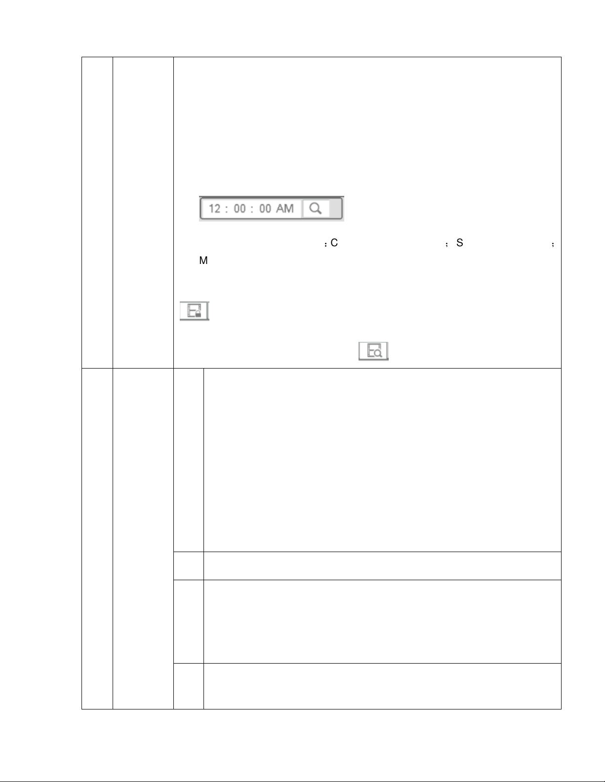
Enter a time in the following search box to start playback for a specific time.
Recorded
file list
Click to view the file list of the selected date and channel
The duration of the files correspond to the value of “Pack Duration” that is set
in Setup->System->General.
Maximum of 128 files can be displayed at once. Double click on a file to start
playback.
9
Playback
control
File types that can be listed:C—continuous recording; S—sensor recording
M—Motion recording.
File lock: Check the box the file to lock and then click the file lock button
. A locked file cannot be overwritten.
Search locked file: Click the button to view locked files.
Play/Pause
There are three ways begin playback.
Play button
►/
■ Stop
Click on the applicable channel and time in the time bar.
Click on a file in the file list.
When in slow play mode, click the play/pause button to resume playback at
normal speed
;
Rewind
│/
│
Press once to start rewind. Press again to pause.
Click play/pause to restore normal playback.
When paused, press to play the next or the previous frame..
59
Page 61

Press ►/ to restore normal playback.
Slow play
10 Time bar
►
In playback mode, press to start slow play. Supported speeds are 1/2x,
1/4x, 1/8x, and 1/16x.
Fast forward
Supported speeds are 2x, 4x, 8x, and 16x.
Audio volume for recorded audio
Pin button.
Displays the record type and the time period for the selected date.
In 2x2 mode, there are four separate time bars for each channel that’s
selected. In other playback modes, there is only one time bar.
Color schemes for the different recording modes are: green for continous,
yellow for motion, and red for sensor.
11
Time bar
unit
12 Backup
13 Clip
• The options are: , , , . Press an option
to divide the entire time bar over the selected time period. Use this option to
quickly choose a time slot for playback more accurately.
Select the file(s) to backup from the file list. Then click the backup button,
which will then bring up the backup menu. Make sure that a USB flash drive or
HDD is inserted in the USB port. Select or create new folder and then click the
Backup button to begin the backup operation.
This function is for editing a file with a specified time period and backing it up.
Press to start the file to edit.
Select the clip start time on the time bar and then press .
60
Page 62

Select the clip stop time on the time bar and then press again.
Press to bring up the backup menu.
Please note:
A maximum of 1024 files can be backed up at the same time.
The clip operation will not work if any files have been checked in the file
list.
14
Record
type and
Sync
Digital
Select which recording modes are shown on the time bar (continuous, motion,
sensor). Sync enables all channels to play back at the same exact time period. If
Sync is unchecked, each channel can play back recordings at different times.
When full-screen playback mode, click and drag to select a section and then left
zoom
click to digitally zoom in. Right click to exit digital zoom.
Other Functions
61
Page 63

4.6.2.1 File list
To see the list of recorded files go to the file list interface. Enter a time at the top right corner to search the
records by time. See image on the left side of Figure 4-45. For example, enter 11:00.00 and then click the
search button to view all recorded files after 11:00.00. See image on the right side of Figure 4-45.
Double click a file to start playback.
Figure 4-45
4.6.2.2 Bookmark Pins
During playback, a bookmark pin can be added to mark an important clip. The pin list can be retrieved from
the playback screen
Add Pin
During playback, click the button to go to the following interface. See Figure 4-46. Add a name for
the event and press OK.
62
Page 64

Figure 4-46
Playback Mark
In single-channel mode, click the Pin Event List button to go to the list interface. Double click on a file
to begin playback.
Bookmark Pin Manager
Click the button on the Search interface to go to the Manager interface. See Figure 4-47.
63
Page 65

Figure 4-47
Modify
Double click on an item, which will bring up a dialogue box to modify the pin name.
Delete
To remove a pin, check the box of a pin and then press Delete.
4.6.3 Snapshot Playback
a) To view recorded snapshots, in the search interface, select Snapshot in the top right section and the
interval
b) Please refer to chapter 4.6.2 to select the snapshot to view.
64
Page 66

4.7 Export
4.7.1 File Backup
In this interface, you can backup to a USB device.
a) Connect a USB flash drive or an external HDD to a USB port on the unit.
b) Go to Main menu->Export as shown in Figure 4-49
Figure 4-48
c) Select the backup device and then select the channel along with the file start time and end time.
d) Click Add and the system will begin the search. All matched files will be listed. System automatically
calculates the required and remaining capacity. See Figure 4-491.
e) System will only backup files with the checkbox enabled before the channel name.
f) When the system completes backup, there will be a prompt indicating successful operation.
65
Page 67

Figure 4-49
Note
During the backup process, click on ESC to exit the current interface. However, the system will
not terminate the backup process.
The file name format is: Channel number+Record type+Time. In the file name, the date format is
Y+M+D+H+M+S. File extension is .dav.
4.7.2 Import/Export
This function allows you to copy the current system configuration to other units. It also supports import,
create new folder, and delete folder.
In Main menu->Setting->System->Import/Export, the configuration file backup interface is shown as below.
See Figure 4-51.
66
Page 68

Figure 4-50
Export: Please connect the USB backup device first and then go to the interface. Click Export and then
there will be a corresponding “Config_Time” folder. Double click the folder to view the backup
configuration files.
Import: Use this function to import the configuration files from a USB device to the unit. You need to
select a folder first. The system will pop up a prompt if there is no configuration file under the selected
folder. After a successful import, the system will reboot to activate the new setup.
Note:
System will not open the config backup interface again if there is a backup operation already in process.
System refreshes the device every time when you go to the config backup and sets current directory as
the root directory of the peripheral device.
67
Page 69

If you go to the configuration backup interface first and then insert the peripheral device, please click the
Refresh button to see the newly added device.
4.7.3 Backup Log
a) Go to Main menu->Info->Log as shown in Figure 4-52.
Figure 4-51
b) Select the log type under the drop-down menu and then set the start time/end time. Click Search to
see log time and event information. Click to view detailed log information.
c) Select log items you want to save and then click the backup button. Select a folder to save the items
to. Click Start to backup.
68
Page 70

4.7.4 USB Device Auto Pop-up
When a USB device is inserted, the system can auto detect it and pop up the following interface. It allows
you to conveniently backup files, log, and configuration or update the system firmware.
Figure 4-52
4.8 Alarm
4.8.1 Alarm Detection
See Figure 4-53 4-55. There are three detection types: motion detection, tampering, and video loss.
4.8.1.1 Motion Detection
Motion setup interface is shown in Figure 4-53 4-54
Event type: Choose the Motion tab at the top
Channel: Select a channel from the dropdown list to configure for motion
Enable: Check the box here to enable motion detection for the selected channel.
69
Page 71

Region: Click the Setup button to set up the motion detection zone. Click and drag the mouse to define
the zone and right click to exit.
Sensitivity: The highest value is the most sensitive. This determines how easily motion alarm will be
triggered.
Anti-dither: This determines how long the motion alarm lasts. The maximum value is 600 seconds. For
example, if the value is set to 10 seconds, the motion alarm will last for 10 seconds even if the actual
motion event only lasts for a couple of seconds.
Period: This is to set the motion detection schedule.
Show message: System can pop up a local notification window when a motion event occurs.
Alarm upload: System can upload the alarm signal to the network.
Send email: System can send out a notification email when a motion event occurs.
Record channel: Select the channel to record to once a motion event occurs.
PTZ activation: PTZ cameras that are on the unit can be set to go to a specific preset when a motion
event occurs.
Delay: This is the post record time. The system can continue to record for the duration of the time that’s
specified after the motion alarm has ended. The value ranges from 10s to 300s.
Sequence: Choose which channels that the unit will sequence through when a motion event occurs.
Snapshot: Take a snapshot of the chosen channels when a motion event occurs.
Voice Prompts: Select an audio file to play when a motion event occurs. Files must be added first
through System->Digital Deterrent.
70
Page 72

Figure 4-53
Figure 4-54
71
Page 73

Figure 4-55
Figure 4-56
72
Page 74

4.8.1.2 Tampering
Note: This function is supported only for cameras that include a tampering detection function.
When a camera is tampered with (lens masking, color change, etc), the system can alert you to
guarantee video continuity. Tampering setup interface is shown in See Figure 4-58.
Sensitivity: The value range is from 1 to 6. Sensitivity is mainly related to brightness in the image.
Note:
During tampering detection, motion detection and video loss functions are not active.
Figure 4-57
4.8.1.3 Video Loss
Note: This function is supported only for cameras that include a video loss detection function.
In Figure 4-53, select the video loss tab. The interface is shown in Figure 4-58. This function allows you
to be notified when video loss occurs.
73
Page 75

Figure 4-58
4.8.2 Notification
There are two types: Disk/Network.
HDD: HDD error, no HDD, no space. See Figure 4-59.
Network: Disconnect, IP conflict, MAC conflict. See Figure 4-60.
Show message: system can pop up the message in the local screen to alert you when an alarm
event occurs.
Send email: System can send out an email notification to alert you when an alarm event occurs.
Voice Prompts: Select an audio file to play when a motion event occurs. Files must be added first
through System->Digital Deterrent.
74
Page 76

Figure 4-59
Figure 4-60
75
Page 77

4.9 Network
4.9.1.1 TCP/IP
The interface is shown in Figure 4-61.
IP Version: IPv4 and IPv6 are supported.
MAC address: Shows the MAC address of the unit.
IP address: Shows the current IP address. If DHCP is disabled, a static IP address can be entered here.
Default gateway: Shows the current gateway. If DHCP is disabled, a gateway can be entered manually.
Note that the IP address and the default gateway must be in the same subnet.
DHCP: If this option is enabled and the unit is on network with DHCP capability, the unit will
automatically have an IP address assigned.
MTU: This sets the MTU value of the network adapter. This determines the maximum size of a packet in
any transmission. The value can range from 1280-1500 bytes. The default value is 1500. The following
MTU values are for reference only.
1500: Ethernet information packet max value and also the default value. This is the typical setup
when there is no PPPoE or VPN. It is the default setup of some routers, switches, and network
adapters.
1492: Recommend value for PPPoE.
1468: Recommend value for DHCP.
Preferred DNS server: DNS server IP address.
Alternate DNS server: DNS server alternate address.
LAN download: If the PC and the NVR are on the same local network, when downloading recordings to
the PC, this option will speed up the download. The download speed is 1.5X or 2.0X of the normal
speed.
After completing setup, click the save button and the system will return to the previous menu.
76
Page 78

Figure 4-61
4.9.1.2 Connection
The connection setup interface is shown in Figure 4-62.
Max connection: system supports a maximum of 128 users. Performance varies depending on the
network bandwidth.
TCP port: Default value is 37777.
UDP port: Default value is 37778.
HTTP port: Default value is 80.
HTTPS port: Default value is 443.
RTSP port: Default value is 554.
Important: System will reboot after any of the above ports are changed. Please make sure the port
values do not conflict.
77
Page 79

Figure 4-62
4.9.1.3 DDNS
DDNS setup interface is shown in Figure 4-63.
Check the Enable box and click on Apply. The DDNS address will be “specoXXXXXX.specoddns.net” with
“XXXXXX” being the last 6 digits of the unit’s MAC address. When connected, the status field will show
“connected”.
78
Page 80

Figure 4-63
4.9.1.4 UPnP (EZ Network)
UPnP is used to establish necessary connections between the device and the router to provide access to the
internet. Please make sure that the default gateway is set under the TCP/IP section. See Figure 4-64 for the
UPnP interface.
Enable: Check to enable UPnP.
Status: Displays the UPnP connection status.
LAN: Value of the default gateway.
WAN: Public IP address of the router.
Port Mapping List
Service name:Default list. More can be defined by the user.
Protocol: Protocol type
Internal port:Port that has been mapped in the router.
External port:Port that has been mapped locally.
79
Page 81

Default: Press Default and then Apply to restore the default list.
Add: Used to add new items to the list
Delete: Used to remove items from the list. Make sure the checkbox for the item is selected first.
Double click an item to view or change the mapping information. See Figure 4-65.
Important:
When setting the external port, please use a port in the range 1024~5000. Do not use ports 1~1023 to
avoid conflicts.
For TCP and UDP, please make sure the internal port and external port are the same to guarantee
proper data transmission.
Figure 4-64
80
Page 82

Figure 4-65
4.9.1.5 Email
The email interface is shown below in Figure 4-66.
SMTP server: Enter the mail server information.
Port: Enter the corresponding port for the mail server.
User name: Enter the user name of the email account.
Password: Enter the password of the email account.
Sender: Enter sender email address that will be displayed in the emails.
Subject: A maximum of 32 characters are supported for the subject.
Receiver: Enter the recipient’s emails address. A maximum of 3 email addresses are supported.
Encryption Type: Choose between SSL and TLS.
Interval: This is to set how often the email gets sent. The range is from 0 to 3600 seconds. 0 means
there is no interval.
Check Status: This function allows the system to send out a test email to check the connection.
Interval: This is for the Check Status interval.
Please note that system will not send out the email immediately when an alarm occurs. The system sends
out the email according to the interval that’s specified. The purposed of this is to reduce heavy loads on the
email server if/when there are too many false alarms occurring.
81
Page 83

Figure 4-66
4.9.1.6 FTP
The FTP interface is shown in Figure 4-67.
Use this section to enter the FTP server address, port, and remote directory. If a remote directory is not
specified, the system will automatically create folders according to the IP, time, and channel.
File length is the upload file size. If the specified value is larger than the actual file size, the system will
upload the entire file. When the value is 0, the system will upload all corresponding files.
After specifiying the channel and weekday, two periods can be set for each channel according to the desired
event type (sensor, motion, or continuous).
Click the Test button to test the FTP connection.
82
Page 84

Figure 4-67
83
Page 85

4.9.2 Network Test
4.9.2.1 Network Test
Go to Main menu->System Info->Network->Test shown in Figure 4-68.
Destination IP: Enter a valid IPV4 address or domain.
Test: The test results can display average delay and packet loss rate. View the network status.
Network Analyzer Backup: Insert a USB drive and click the Refresh button to view the device. Use the
dropdown list to select the device. Click the Browse button to select the path.
Click the button on the right panel to begin the network packet analyzer. At this point, all network
operations will be backed up. Please go back to the interface and click to stop. System will save the
packets to the specified path.
Figure 4-68
84
Page 86

4.9.2.2 Network Load
Go to Main menu->Info->Network->Load, shown in Figure 4-69. View statistics of the device network adapter.
Connection status is shown as offline if disconnected.
Figure 4-69
85
Page 87

4.10 HDD Setup
View HDD information such as type, status, total capacity, record time, etc.
4.10.1 Format
a) Go to Main menu->Setup->Storage->Manage HDD shown in Figure 4-70.
Figure 4-70
b) Select the HDD and then select Format.
c) Click the OK button to complete the format. The system will need to restart.
Important: This will erase all recorded data on the system. This option will not reset any system settings.
86
Page 88

4.10.2 HDD Information
Shows hard drive type, total space, free space, and status. See Figure 4-71.
Go to Main menu->System Info->System->HDD Info
If the drive is damaged, the system will show “?”.
Figure 4-71
Click the icon under the S.M.A.R.T column to bring up the interface is shown in Figure 4-72.
87
Page 89

Figure 4-72
88
Page 90

4.11 General System Setup
4.11.1 Device Setup
Go to Main menu->Setup->System->General for the general setup interface.
Pack duration: Recording duration for a single file. The value ranges from 0 to 120 minutes. Default
value is 60 minutes.
Device Name: Specify a name for the unit. This name can be used to differentiate between multiple
units.
Language: Choose between English, Spanish, and French.
Video standard: NTSC
HDD Full: Choose between two options - stop recording or overwrite.
Instant Playback: Within live view, a single channel can be chosen for playback. The value ranges from
5 to 60 minutes.
Auto logout: If a logged in user remains inactive for the duration of the specified time, the user will be
logged out. Value ranges from 0 to 60 minutes.
Navigation bar: Check to display the navigation bar on the interface.
Camera Time Sync: The system will synchronize the time between the NVR and the IP cameras at the
intervals specified.
EZ Setup: If enabled, the system will go to the startup wizard directly when the system is rebooted.
Otherwise, it will go to the login interface.
Mouse sensitivity: Sets the double-click speed of the mouse.
89
Page 91

Figure 4-73
4.11.2 Date and Time
Go to Main menu->Setup->System->General, shown in Figure 4-74
System Time: Set the time of the system
Date format: There are three types: YYYY-MM-DD, MM-DD-YYYY, or DD-MM-YYYY.
Date separator: There are three types.
DST: Set the start and end dates for Daylight Saving Time. DST must be enabled to use this function.
Time format: Choose between 24-hour mode or 12-hour mode.
NTP: Specify an NTP server to synchronize the time.
Note:
Do not modify the system time unless it is important.
Before modification, please stop recording.
90
Page 92

Figure 4-74
91
Page 93

4.12 Device Maintenance and Manager
4.12.1 System Info
4.12.1.1 Version
Go to Main menu->System Info->System->Version, shown in Figure 4-75.
Figure 4-75
4.12.1.2 Bitrate
See Figure 4-76, for information on cameras connected to the unit.
Figure 4-76
92
Page 94

4.12.1.3 Online User
Manage online users connected to the NVR. See Figure 4-77.
Click the button to disconnect or block one user. Note that only an administrator can perform this
function. The NVR detects when there are any newly added or deleted users every five seconds and then
refreshes the list automatically.
Figure 4-77
93
Page 95

4.12.1.4 Remote Device Information
Go to Main Menu->System Info->Status to view the channel status of the remote device, connection log, etc.
See Figure 4-78.
Figure 4-78
94
Page 96

4.12.1.5 Camera
4.12.1.5.1 Status
View the IP Camera status of connected channels. See Figure 4-79.
Connection status: : Connection success. : Connection failed.
Refresh: Click to refresh the status of the connected channels.
4.12.1.5.2 Firmware
View camera information. See Figure 4-80.
Figure 4-79
95
Page 97

Figure 4-80
4.12.2 Log
Go to Main Menu->System Info->Log, shown in Figure 4-81.
Start time/End time: Please select the start and end time and then click search. The log files will be
displayed in a list. The system can display 100 logs on one page. Up to 1024 log files can be saved.
Use page up/down buttons on the interface to view more.
Tips
Double click on a log item to view detailed information. See Figure 4-82.
96
Page 98

Figure 4-81
Figure 4-82
97
Page 99

4.12.3 Digital Deterrent
Digital Deterrent can be used to play an audio file when an alarm occurs.
4.12.3.1.1 File Manage
Add audio files, listen to an audio file, or rename/delete audio files. See Figure 4-83.
Figure 4-83
Click the Add button, to add an audio file via USB. Supported audio formats are MP3 and PCM. See Figure
4-84.
98
Page 100

4.12.4 Account
See Figure 4-85. This section is used for:
Add new user
Modify user
Add group
Modify group
Modify password.
For account management please note:
Figure 4-84
For the user account name and the user group, a space in front of or at the back of the string is invalid.
There can be a space in the middle. The string can include letters, numbers, underline, dash, and dot.
The default user amount is 64 and the default group amount is 20. There is no limit to group or user
amount.
For group or user management, there are two levels: admin and user.
There are two default users: admin and hidden user “default”.
99
 Loading...