

Page 1
N8NXP
!
!
!
NXP (8 and 16 Channel)
Quick Start Guide!
!
!
!
!
!
!
!
!
!!!!!!!!!!!!!!!!!
!
!
Version 1.0.1
!
Features and specifications subject to change, please check www.specotech.com for firmware updates.
N16NXP
Page 2
1
Welc om e!
Thank you for purchasing this NVR.
This guide is designed to be a quick reference for installing the system.
Please read this guide carefully before installing and operating the unit.
For more detailed information, please refer to the user manual.
If technical assistance is needed, please contact Speco Technologies Technical Support.
Phone: 1-800-645-5516 option 3
Email: techsupport@specotech.com
Important Safeguards and Warnings
! Speco Technologies assumes no liability or responsibility for any fires or electrical shock caused by improper
handling or installation.
! Speco Technologies is not liable for any problems caused by unauthorized modifications or attempted repair.
Note: All of the installation and operations here should conform to your local electric safety rules.
!
!
!
1. Contents
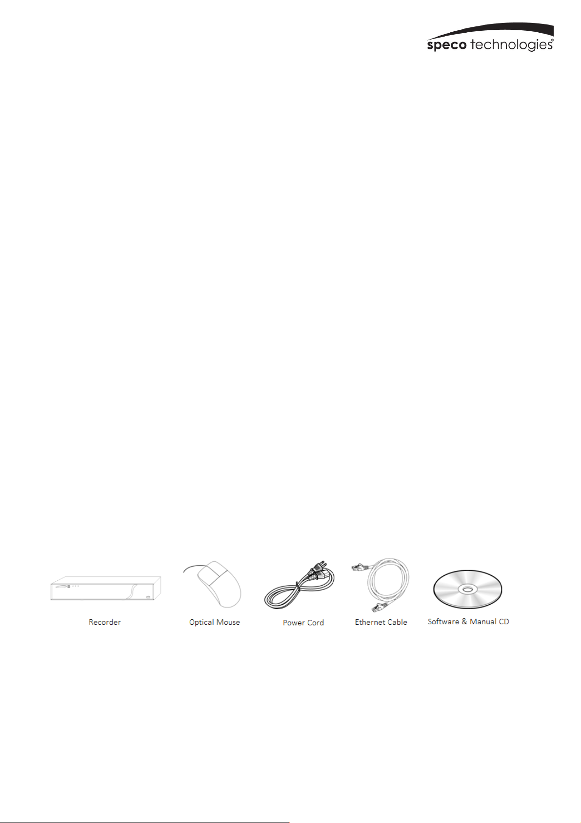
1.1 Check Unit and Accessories
After unpacking the unit, please check for any visible damage. Then check to make sure that all accessories are included.
Check that the model number and serial number that’s listed on the label on the unit are the same as what’s listed on the
package label.
!
!
!
!
!
Page 3
2
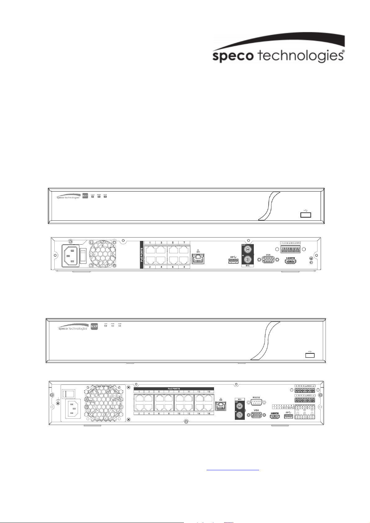
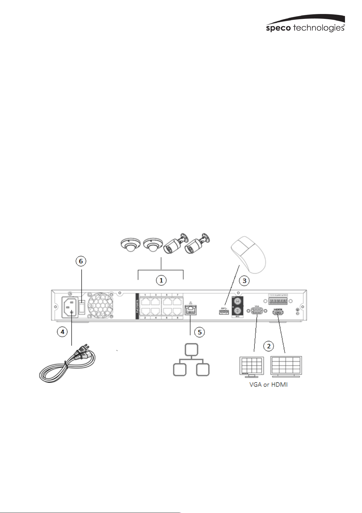
1.2 Connections
To quickly get started, connect the following to your recorder in the following order, please refer to Figure 1-2 (N8NXP
shown for reference).
1. Connect IP cameras to the PoE ports of the recorder.
2. Connect a monitor to the recorder via VGA or HDMI cable (not included).
3. Connect the included optical mouse into any USB port of the recorder.
4. Connect the power cord to the recorder and plug into a 120VAC 50/60Hz outlet.
5. Connect recorder to network (optional)
6. Turn on power switch and allow recorder to boot up.
!
!
!
!
Figure 1-2
! !
Page 4
3
!
!
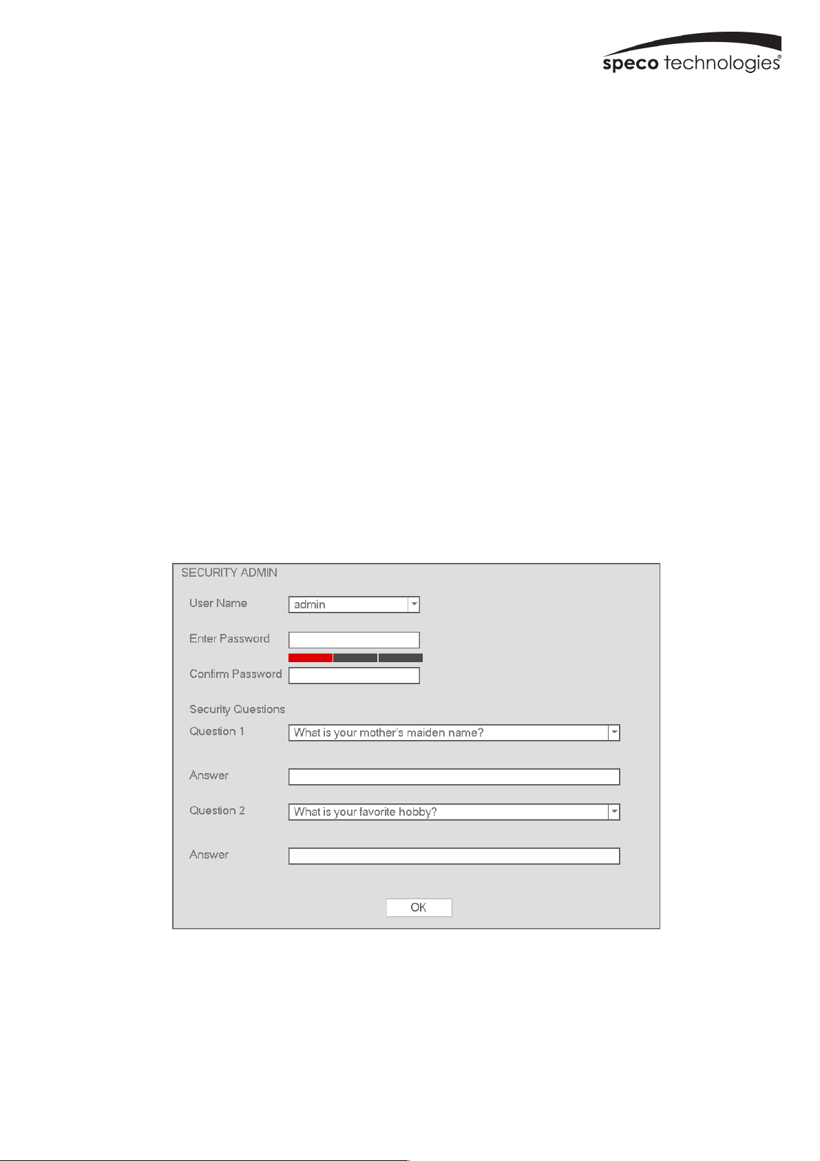
2. Set Password and Security Questions
2.1 Enter a password
Note: You will be prompted to set a Password and security questions upon initial bootup. see Fig 2-1
The default login ID and administrator username is: admin
The password strength indicator can be used as a reference. Re-enter the password to confirm.
2.2 Enter answers for two security questions.
You can select which security questions to provide answers for. It is important that you remember the answers for these
questions or you will not be able to reset your password and be locked out.
Note: These questions must be answered correctly when resetting the password.
WARNING: 5 incorrect login attempts within 30 minutes will result in a lock on the account.
!
!
Figure 2-1
Page 5

4
3. Update Firmware (if necessary)
Speco will continuously make improvements, please check the website to ensure you are running the latest firmware
version.
3.1 Check firmware version on recorder
Go to Main menu->System Info->System->Version, shown in Figure 3-1. Please note the build date on your recorder.
Figure 3-1
3.2 Check latest firmware version on website
Go to www.specotech.com, then click on Support, then Recorder Software updates and follow the prompts until you find
the model of your recorder. Then compare the release date of the firmware on the website with the recorder’s build date.
See Figure 3-2 and 3-3.
!
!
Figure 3-2
Page 6

5
!
Figure 3-3
If the web has a more recent firmware version than your recorder’s build date, then please update your device to the
latest firmware.
3.3 Updating Firmware
3.1 Download the firmware from the website on to a USB disk.
Insert USB disk into available USB port on the recorder. A prompt should show that the drive is detected, select ‘System
upgrade’ and click on the new firmware file to upload. See Figure 3-4
Figure 3-4
After firmware is updated, the unit will restart. You can now remove the USB disk from the unit.
Page 7

6
4. EZ Setup
After the system boots up, the EZ Setup wizard is displayed. See Figure 4. If not, right click, and select EZ Setup.
!
Figure 4
Tip: Check the “Startup” box to display the EZ Setup wizard every time the device is rebooted.
4.1 General Settings – Date & Time
Go to Main menu->Setup->System->General, shown in Figure 4-1
! System Time: Set the time and date format of the system
! DST: Set the start and end dates for Daylight Saving Time. DST must be enabled to use this function.
! Time format: Choose between 24-hour mode or 12-hour mode.
! NTP: Specify an NTP server to synchronize the time.
Figure 4-1
Page 8

7
4.2 Camera Setup
The NVR supports plug and play for IP cameras through the built-in PoE ports.
If desired, you can scan for IP cameras that are on the same local network through the EZ Camera feature.
To add cameras, right click and then click on Main menu->Setup->Camera->Site Locate. See Figure 4-2.
!
Figure 4-2
Click Device Search to find cameras on the local network.
Double click on a camera to add it to the NVR.
4.3 Schedule Setup
To set up schedule recording, go to Main Menu->Setup->Storage->Schedule. See figure 4-3
! Channel: Select the desired channel number first. You can select “all” if you want to set the schedule for all of the
channels.
" : Select icon of multiple days to link them together. This will allow the linked days to be edited
simultaneously.
" : Click to delete the schedule for the selected recording type from one period.
! Recording Type: Check the box of the desired recording type. There are three modes for recording: Continuous / Motion
detection / Sensor.
! Week day: There are eight options: ranges from Saturday to Sunday and all.
! Holiday: Special schedules can be set for holidays if needed. Holidays must be added manually. To add a holiday, go to
Main Menu->Setup->System->General->Holiday. This option will not be shown if no holidays have been added.
! Pre-record: This option is to set up the pre-record interval for events. The range is from 1 to 30 seconds.
! SD Backup: For supported IP camera models, the video can be recorded to an SD card in case the network connection
fails. The time range is from 0 to 43200 seconds. After the network connection resumes, the NVR will retrieve the video
from the SD card.
Page 9

8
! Period setup: Click to bring up the interface to enter a time period manually.
Follow the steps listed below to visually draw the period.
a) Select the desired channel.
b) Set the recording type.
c) Click and drag. See Figure 4-3. Note: for all schedules, a maximum of 6 separate periods can be
specified for a day.
Figure 4-3
After completing setup, click Apply to save the settings.
4.4 Motion Recording
1. Go to Main Menu->Setup->Event->Video->Motion. See Figure 4-4.
Page 10

9
!
Figure 4-4
2. Select a channel from the dropdown list and then check the Enable box to enable motion detection.
3. Select the Region Setup button to set up the motion detection zone. Click and drag to identify the desired zones.
Multiple areas within the window can be highlighted.
4. Period: Select the Period Setup button. The interface is shown below (Figure 4-5). Follow the same procedure as
the general schedule setup. Note that a maximum of 6 separate periods can be specified for one day.
Figure 4-5
Page 11

10
4.5 Playback
Right click and select Main Menu->Search to bring up the playback interface as shown in Figure 6. From this screen, you
can access EZ Search as well as searching by timeframe.
Figure 4-6
Tip: Check the “Sync” box to sync cameras to the same time index during playback.
5. Remote Web Access
1. Open Internet Explorer and enter the NVR’s IP address in the address bar.
2. Follow the instructions to install the plug-in.
3. After installation, the login interface is shown as below. See Figure 5-1.
4. Please enter the user name and password.
Figure 5-1
For detailed operation information, please refer to the user’s manual.
Page 12

11
!
!!! +!
NXP Camera Compatibility Chart
Camera Function Resolution Housing Format PoE Type Zoom Focal Length IR Range Weather Rating Color Included Accessory Compression Certification
O2LPR67
Monochrome License Plate Capture 2MP Bullet IP 802.3af 10x 5-50mm 165 IP66 White N/A H.265, H.264, MJPEG FCC, RoHS
O2P12X
PTZ (pan/tilt/zoom) 2MP Dome IP 802.3at 12x 5.1-61.1mm N/A IP66 White Wall Bracket H.264, MJPEG FCC, RoHS, UL
O2P4X
PTZ (pan/tilt/zoom) 2MP Dome IP 802.3af 4x 2.7-11mm N/A IP66 White Junction Box H.264, MJPEG FCC, RoHS, UL
O3VFBM
Motorized varifocal lens, auto focus 3MP Bullet IP 802.3af 4.5x 2.7-12mm 190 IP67 Gray Junction Box H.264, MJPEG FCC, RoHS, UL
O3VFDM
Motorized varifocal lens, auto focus 3MP Dome IP 802.3af 4.5x 2.7-12mm 98 IP67 White Junction Box H.264, MJPEG FCC, RoHS, UL
O3VLB3
Fixed lens 3MP Bullet IP 802.3af N/A 2.8mm 98 IP67 Gray Junction Box H.264, MJPEG FCC, RoHS, UL
O4D1
Fixed lens 4MP Dome IP 802.3af N/A 2.8mm 98 IP67 White Junction Box H.264, MJPEG FCC, RoHS, UL
O4B7
Fixed lens 4MP Bullet IP 802.3af N/A 2.8mm 98 IP67 Gray Junction Box H.264, MJPEG FCC, RoHS, UL
O4P30X
PTZ (pan/tilt/zoom) 4MP Dome IP 802.3at 30x 4.5-135mm N/A IP66 White Wall Bracket H.264, MJPEG FCC, RoHS, UL
O8B2M
Ultra high definition, motorized, auto focus 4K Bullet IP 802.3af 4.5x 2.7-12mm 160 IP67 Gray Junction Box H.264, MJPEG FCC, RoHS, UL
O8D2M
Ultra high definition, motorized, auto focus 4K Dome IP 802.3af 4.5x 2.7-12mm 160 IP67 White Junction Box H.264, MJPEG FCC, RoHS, UL
 Loading...