

Page 1

Page 2

Page 3
Digital Video Recorder
WARNING
RISK OF ELECTRIC SHOCK
DO NOT OPEN
WARNING: TO REDUCE THE RISK OF ELECTRIC SHOCK,
DO NOT REMOVE COVER (OR BACK).
NO USER-SERVICEABLE PARTS INSIDE.
REFER SERVICING TO QUALIFIED
SERVICE PERSONNEL.
The lightning flash with arrowhead symbol, within an equilateral triangle, is intended to alert
the user to the presence of uninsulated "dangerous voltage" within the product’s enclosure
that may be of sufficient magnitude to constitute a risk of electric shock.
The exclamation point within an equilateral triangle is intended to alert the user to the presence
of important operating and maintenance (servicing) instructions in the lite rature accompanying
the appliance.
COMPLIANCE NOTICE OF FCC:
THIS EQUIPMENT HAS BEEN TESTED AND FOUND TO COMPLY WITH THE LIMITS FOR A CLASS A DIGITAL
DEVICE, PURSUANT TO PART 15 OF THE FCC RULES. THESE LIMITS ARE DESIGNED TO PROVIDE
REASONABLE PROTECTION AGAINST HARMFUL INTERFERENCE WHEN THE EQUIPMENT IS OPERATED IN
A COMMERCIAL ENVIRONMENT. THIS EQUIPMENT GENERATES, USES, AND CAN RADIATE RADIO
FREQUENCY ENERGY AND IF NOT INSTALLED AND USED IN ACCORDANCE WITH THE INSTRUCTION
MANUAL, MAY CAUSE HARMFUL INTERFERENCE TO RADIO COMMUNICATIONS. OPERATION OF THIS
EQUIPMENT IN A RESIDENTIAL AREA IS LIKELY TO CAUSE HARMFUL INTERFERENCE, IN WHICH CASE
USERS WILL BE REQUIRED TO CORRECT THE INTERFERENCE AT THEIR OWN EXPENSE.
WARNING: CHANGES OR MODIFICATIONS NOT EXPRESSLY APPROVED BY THE PARTY RESPONSIBLE FOR
COMPLIANCE COULD VOID THE USER’S AUTHORITY TO OPERATE THE EQUIPMENT.
THIS CLASS OF DIGITAL APPARATUS MEETS ALL REQUIREMENTS OF THE CANADIAN INTERFERENCECAUSING EQUIPMENT REGULATIONS.
The information in this manual is believed to be accurate as of the date of publication. We are not responsible for any
problems resulting from the use thereof. The information contained herein is subject to change without notice. Revisions
or new editions to this publication may be issued to incorporate such changes.
The software included in this product contains so me Open Source s. You may obta in the complet e corresponding sour ce
code from us. See the Open Source Guide on th e software CD (OpenSourceGu ide\OpenSourceGuide.pd f) or as a printed
document included along wit h the Oper atio n Instr uct ion.
i
Page 4
Operation Instruction
Important Safeguards
1. Read Instructions
All the safety and operating instructions should be read before the
appliance is operated.
2. Retain Instructions
The safety and operating instructions should be retained for future
reference.
3. Cleaning
Unplug this equipment from the wall outlet befo re cleaning it . Do not
use liquid aerosol cleaners. Use a damp soft cloth for cleaning.
4. Attachments
Never add any attachments and/or equipment without the approval of
the manufacturer as such additions may result in the risk of fire, electric
shock or other personal injury .
5. Water and/or Moisture
Do not use this equipment near water or in contact with water.
6. Ventilation
Place this equipment only in an upright position. This equipment has an
open-frame Switching Mode Power Supply (SMPS), which can cause a
fire or electric shock if anything is inserted through the ventilation holes
on the side of the equipment.
7. Accessories
Do not place this equipment on an unstable cart, stand or table. The
equipment may fall, causing serious injury to a child or adult, and
serious damage to the equipment. Wall or shelf mounting should follow
the manufacturer's instruction s, and sho uld use a m ounting k it approve d
by the manufacturer.
This equipment and cart combination should be moved with care. Quick
stops, excessive force, and uneven surfaces may cause the equipment
and cart combination to overturn.
8. Power Sources
This equipment should be operated only from the type of power source
indicated on the marking label. If y ou are n ot sure of t he type of power,
please consult your equipment dealer or local power company.
9. Power Cords
Operator or installer must remove power and TNT connections before
handling the equipment.
10. Lightning
For added protection for this equipment during a lightning storm, or when
it is left unattended and unused for long periods of time, unplug it from the
wall outlet and disconnect the antenna or cable system. This will prevent
damage to the equipment due to lightning and power-line surges.
11. Overloading
Do not overload wall outlets and exte nsion cords a s this can result in t he
risk of fire or electric shock.
12. Objects and Liquids
Never push objects of any kind through openings of this equipment as they
may touch dangerous voltage points or short out parts that could result in a
fire or electric shock. Never spil l liquid of any kind on the equipment.
13. Servicing
Do not attempt to service this e quipment y ourself. Refer al l servicing to
qualified service personnel.
14. Damage requiring Service
Unplug this equipment from the wall outlet and refer servicing to
qualified service personnel under the following conditions:
A. When the power-supply cord or the plug has been damaged.
B. If liquid is spilled, or objects have fallen into the equipment.
C. If the equipment has been exposed to rain or water.
D. If the equipment does not operate normally by following the operating
instructions, adjust only those controls that are covered by the operating
instructions as an improper adjustment of other controls may result in
damage and will often require extensive work by a qualified technician
to restore the equipment to its normal operation.
E. If the equipment has been dropped, or the cabinet damaged.
F. When the equipment exhibits a disti nct change in performance ─ this
indicates a need for service.
15. Replacement Parts
When replacement parts are required, be s ure the serv ice technici an has
used replacement parts specified by the manufacturer or that have the same
characteristics as the original part. Unauthorized substitutions may result
in fire, electric shock or other hazards.
16. Safety Check
Upon completion of any service or repairs to this equipment, ask the service
technician to perform safety checks to determ
proper operating condition.
17. Field Installation
This installation should be made by a qualified service person and
should conform to all local codes.
18. Correct Batteries
Warning: Risk of explosion if battery is replaced by an incorrect type.
Dispose of used batteries according to the instructions.
19. Tmra
A manufacturer’s maximum recommended ambient temperature (Tmra)
for the equipment must be specified so that the customer and installer may
determine a suitable maximum operating environment for the equipment.
20. Elevated Operating Ambient Temperature
If installed in a closed or multi-unit rack assembly, the operating ambient
temperature of the rack environment may be greater than r oom am bient.
Therefore, consideration should be given to installing the equipment in an
environment compatible with the manufacturer’s maximum rated am bient
temperature (Tmra).
21. Reduced Air Flow
Installation of the equipment in the rack should be such that the amount
of airflow required for safe operation of the equipment is not compromised.
22. Mechanical Loading
Mounting of the equipment in the rack should be such that a hazardous
condition is not caused by uneven mechanical loading.
23. Circuit Overloading
Consideration should be given to connection of the equipment to supply
circuit and the effect that overloading of circuits might have on over current
protection and supply wiring. Appropriat e considerat ion of equipment
nameplate ratings should be used when addressing this concern.
24. Reliable Earthing (Grounding)
Reliable grounding of rack mounted equipment should be maintained.
Particular attention should be given to supply connections other than direct
connections to the branch circuit (e.g., use of power strips).
ine that the equipment is in
WEEE (Waste Electrical & Electronic Equipment)
Correct Disposal of This Product
(Applicable in the European Union and other European countries with separate collection systems)
This marking shown on the product or its literature, indicates that it should not be disposed with other household wastes at the
end of its working life. To prevent possible harm to the environment or human health from uncontrolled waste disposal, please
separate this from other types of wastes and recycle it responsibly to promote the sustainable reuse of material resources.
Household users should contact either the retailer where they purchased this pro duct, or their local government office, for
details of where and how they can take this item for environmentally safe recycling.
Business users should contact their supplier and check the terms and conditions of the purchase contract. This product should
not be mixed with other commercial wastes for disposal.
ii
Page 5

Digital Video Recorder
Table of Contents
Chapter 1 — Introduction ........................................................................................................... 1
Feature ................................................................................................................................... 1
Technical Overview ................................................................................................................ 1
Chapter 2 — Installation ............................................................................................................. 3
Package Contents .................................................................................................................. 3
Required Installation Tools .................................................................................................... 3
Video Input......................................................................................................................... 3
Video Loop Through .......................................................................................................... 4
eSATA Port ........................................................................................................................ 4
Network Port ...................................................................................................................... 4
Video Out ........................................................................................................................... 4
Alarm Input/Output ............................................................................................................ 4
RS232C Port ..................................................................................................................... 5
Factory Reset Switch ......................................................................................................... 5
RS485 Port ........................................................................................................................ 5
Audio In/Out ....................................................................................................................... 5
Power Cord Connector ...................................................................................................... 6
Chapter 3 — Configuration ........................................................................................................ 7
Front Panel Controls .............................................................................................................. 7
Power LED......................................................................................................................... 7
HDD LED ........................................................................................................................... 7
Camera Buttons ................................................................................................................. 7
Menu Button ...................................................................................................................... 8
Copy Button ....................................................................................................................... 8
Esc Button ......................................................................................................................... 8
Play/Stop Button ................................................................................................................ 8
Alarm Button ...................................................................................................................... 8
Sequence Button ............................................................................................................... 8
PTZ Button......................................................................................................................... 8
Mode Button ...................................................................................................................... 8
Arrow Buttons .................................................................................................................... 8
Enter Button
Jog Dial .............................................................................................................................. 9
Shuttle Ring ....................................................................................................................... 9
USB Port ............................................................................................................................ 9
Remote Control Buttons....................................................................................................... 10
ID Button .......................................................................................................................... 10
Camera Buttons ............................................................................................................... 10
Sequence Button ............................................................................................................. 10
Login/Logout Button ........................................................................................................ 10
Arrow Buttons .................................................................................................................. 11
Menu Button .................................................................................................................... 11
Playback Buttons ............................................................................................................. 11
Alarm Button .................................................................................................................... 11
Layout Button .................................................................................................................. 11
Zoom Button .................................................................................................................... 11
....................................................................................................................... 9
iii
Page 6

Operation Instruction
PTZ Button....................................................................................................................... 11
Enter Button ..................................................................................................................... 11
Esc Button ....................................................................................................................... 11
PTZ Control Buttons ........................................................................................................ 12
Copy Button ..................................................................................................................... 12
Play/Stop Button .............................................................................................................. 12
Turning on the Power ........................................................................................................... 12
Initial Unit Setup ................................................................................................................... 12
Setup Screen ....................................................................................................................... 13
System Setup ....................................................................................................................... 13
General ............................................................................................................................ 13
Date/Time ........................................................................................................................ 21
User ................................................................................................................................. 22
Storage ............................................................................................................................ 24
Monitoring ........................................................................................................................ 25
Capacity Estimator .......................................................................................................... 26
Recording Setup .................................................................................................................. 27
General ............................................................................................................................ 27
Schedule .......................................................................................................................... 28
Pre-Event ......................................................................................................................... 30
Archive ............................................................................................................................. 31
Event Setup ......................................................................................................................... 32
Motion .............................................................................................................................. 32
Alarm-In ........................................................................................................................... 33
Video Loss ....................................................................................................................... 34
Video Blind....................................................................................................................... 35
Text-In .............................................................................................................................. 35
Network ............................................................................................................................ 37
Network Setup ..................................................................................................................... 38
General ............................................................................................................................ 38
IP Address ....................................................................................................................... 40
DVRNS ............................................................................................................................ 42
RTSP ............................................................................................................................... 43
ation ....................................................................................................................... 44
Notific
Device Setup ........................................................................................................................ 46
Local Audio ...................................................................................................................... 46
Network Audio ................................................................................................................. 47
Digital Deterrent ............................................................................................................... 48
Alarm-Out ........................................................................................................................ 50
Remote Control ............................................................................................................... 51
Display Setup ....................................................................................................................... 51
OSD ................................................................................................................................. 51
Primary Monitor ............................................................................................................... 52
Spot Monitor .................................................................................................................... 53
Status Setup ........................................................................................................................ 54
Event ................................................................................................................................ 54
Storage ............................................................................................................................ 55
Camera Setup ...................................................................................................................... 55
General ............................................................................................................................ 55
PTZ .................................................................................................................................. 56
Network Camera .............................................................................................................. 57
iv
Page 7

Digital Video Recorder
Chapter 4 — Operation ............................................................................................................ 61
Turning on the Power ........................................................................................................... 61
Live Monitoring ..................................................................................................................... 61
Live Monitoring Menu ...................................................................................................... 62
Active Cameo Mode ........................................................................................................ 64
Zoom Mode...................................................................................................................... 64
PTZ Mode ........................................................................................................................ 64
Event Monitoring .............................................................................................................. 65
Covert Camera ................................................................................................................ 66
Spot Monitoring ............................................................................................................... 66
Recording Video .................................................................................................................. 66
Panic Recording .............................................................................................................. 67
Recording Audio .................................................................................................................. 67
Playing Recorded Video ...................................................................................................... 67
Searching Video ................................................................................................................... 68
Search Menu ................................................................................................................... 69
Event Log Search ............................................................................................................ 71
Record Table Search ....................................................................................................... 73
Motion Search ................................................................................................................. 74
Text-In Search ................................................................................................................. 76
EZ Search ........................................................................................................................ 77
Bookmarks ....................................................................................................................... 78
Clip-Copy ......................................................................................................................... 78
Print ................................................................................................................................. 80
Disk Mirroring ....................................................................................................................... 80
Appendix .................................................................................................................................. 83
USB Hard Disk Drive Preparation ........................................................................................ 83
Text-In Search Examples..................................................................................................... 83
Search Example I ............................................................................................................ 83
Search Example II ........................................................................................................... 84
Speco Remote ..................................................................................................................... 85
Web Monitoring
Mode ..................................................................................................... 86
Web Search Mode ........................................................................................................... 87
Time Overlap ....................................................................................................................... 88
Remote Setup of Network Devices ...................................................................................... 89
Connector Pin Outs .............................................................................................................. 92
I/O Connector Pin Outs ................................................................................................... 92
RS485 Connector Pin Outs ............................................................................................. 92
Map of Screens .................................................................................................................... 93
Error Code Notices .............................................................................................................. 94
System Log Notices ............................................................................................................. 95
Troubleshooting ................................................................................................................... 95
Specifications ....................................................................................................................... 96
v
Page 8

Operation Instruction
List of Illustrations
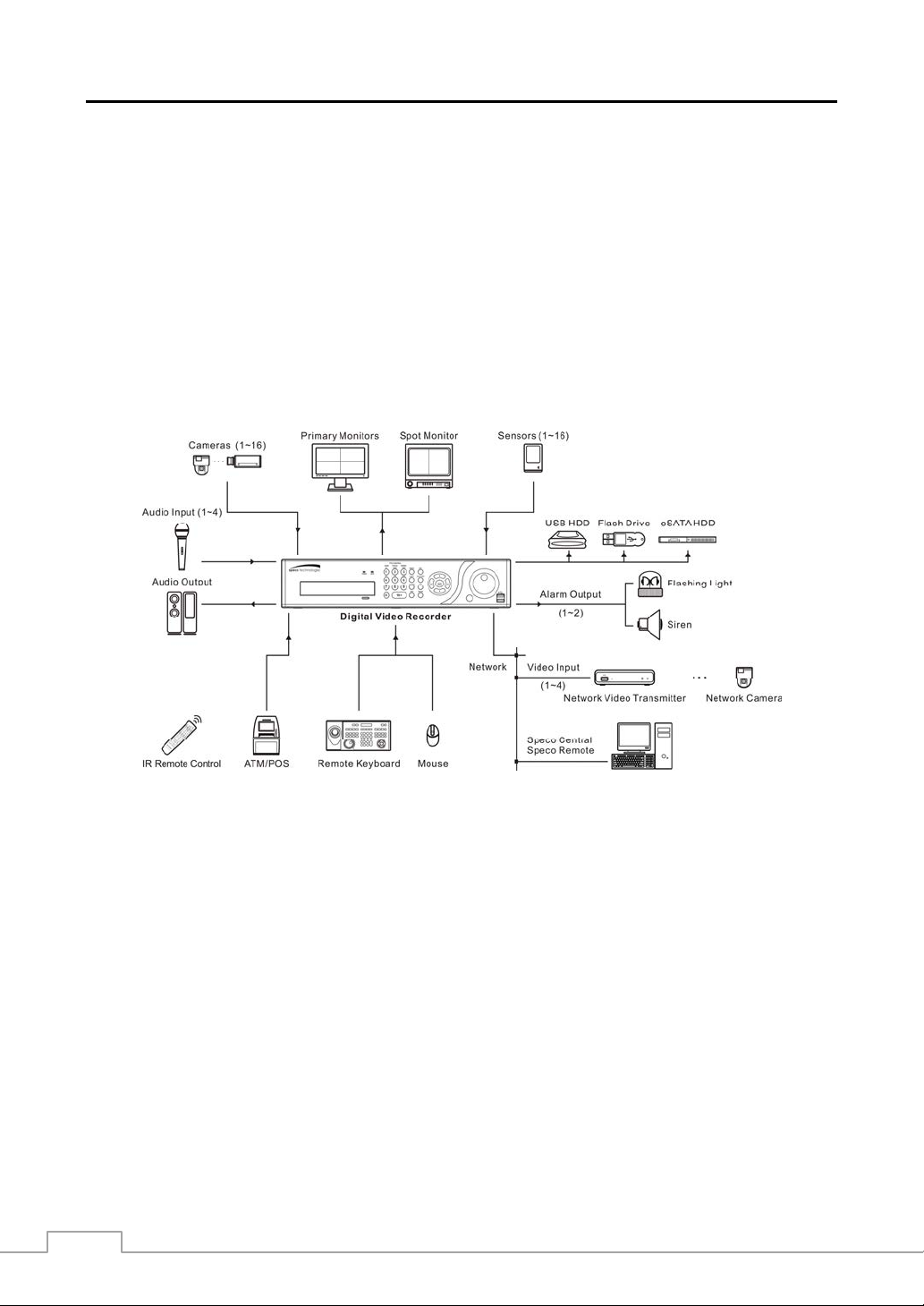
Figure 1 : Typical DVR installation. ....................................................................................................................... 2
Figure 2 : 16-Channel DVR rear panel. ................................................................................................................ 3
Figure 3 : 16-Channel DVR front panel. ............................................................................................................... 7
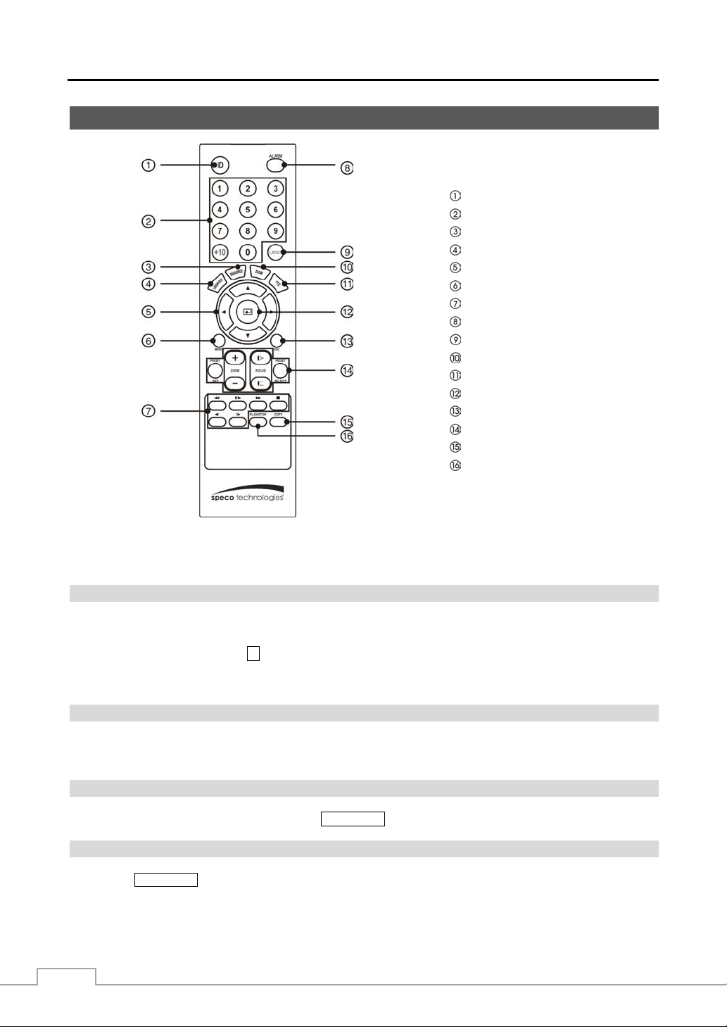
Figure 4 : Infrared remote control. ...................................................................................................................... 10
Figure 5 : Login screen. ...................................................................................................................................... 12
Figure 6 : Logout screen. .................................................................................................................................... 12
Figure 7 : Setup screen. ...................................................................................................................................... 13
Figure 8 : System – General setup screen. ........................................................................................................ 14
Figure 9 : System – Date/Time setup screen. .................................................................................................... 21
Figure 10 : System – User setup screen. ........................................................................................................... 22
Figure 11 : System – Storage setup screen. ...................................................................................................... 24
Figure 12 : System – Monitoring setup screen. .................................................................................................. 25
Figure 13 : System – Capacity Estimator setup screen...................................................................................... 26
Figure 14 : Record – General setup screen. ...................................................................................................... 27
Figure 15 : Record – Schedule setup screen. .................................................................................................... 28
Figure 16 : Schedule – Settings (Advanced Mode) setup screen. ..................................................................... 29
Figure 17 : Record – Pre-Event setup screen. ................................................................................................... 30
Figure 18 : Record – Archive setup screen. ....................................................................................................... 31
Figure 19 : Event – Motion setup screen. ........................................................................................................... 32
e 20 : Event – Alarm-In setup screen. ........................................................................................................ 33
Figur
Figure 21 : Event – Video Loss setup screen. .................................................................................................... 34
Figure 22 : Event – Video Blind setup screen. ................................................................................................... 35
Figure 23 : Event – Text-In setup screen. .......................................................................................................... 36
Figure 24 : Text-In Device screen. ...................................................................................................................... 36
Figure 25 : Event – Network setup screen. ........................................................................................................ 37
Figure 26 : Network – General setup screen. ..................................................................................................... 38
Figure 27 : Network – IP Address (Manual) setup screen. ................................................................................. 40
Figure 28 : Network – DVRNS setup screen. ..................................................................................................... 42
Figure 29 : Network – RTSP setup screen. ........................................................................................................ 43
Figure 30 : Network – Notification setup screen. ................................................................................................ 44
Figure 31 : Device – Local Audio setup screen. ................................................................................................. 47
Figure 32 : Device – Network Audio setup screen. ............................................................................................ 47
Figure 33 : Device – Digital Deterrent setup screen. .......................................................................................... 48
Figure 34 : Device – Alarm-Out setup screen. ................................................................................................... 50
Figure 35 : Device – Remote Control setup screen. ........................................................................................... 51
Figure 36 : Display – OSD setup screen. ........................................................................................................... 51
Figure 37 : Display – Primary Monitor setup screen. .......................................................................................... 52
Figure 38 : Display – Spot Monitor setup screen. ............................................................................................... 53
e 39 : Status – Event setup screen. ........................................................................................................... 54
Figur
Figure 40 : Status – Storage setup screen. ........................................................................................................ 55
Figure 41 : Camera – General setup screen. ..................................................................................................... 56
Figure 42 : Camera – PTZ setup screen. ........................................................................................................... 56
Figure 43 : Camera – Network Camera setup screen. ....................................................................................... 57
Figure 44 : Live Monitoring menu. ...................................................................................................................... 61
Figure 45 : PTZ Select Camera menu. ............................................................................................................... 64
Figure 46 : PTZ Preset menu. ............................................................................................................................ 65
Figure 47 : Select Playback Camera menu. ....................................................................................................... 67
Figure 48 : Search menu. ................................................................................................................................... 68
Figure 49 : Event Log Search screen. ................................................................................................................ 71
Figure 50 : Record Table Search screen. ........................................................................................................... 73
Figure 51 : Motion Search screen. ...................................................................................................................... 74
Figure 52 : Text-In Search screen. ..................................................................................................................... 76
Figure 53 : Bookmarks screen. ........................................................................................................................... 78
Figure 54 : Clip-Copy screen. ............................................................................................................................. 78
Figure 55 : Print screen. ...................................................................................................................................... 80
Figure 56 : System – Storage setup screen. ...................................................................................................... 81
vi
Page 9

Digital Video Recorder
Chapter 1 — Introduction
Feature
Your color digital video recorder (DVR) provides recording capabilities for eight or 16 camera inputs. It provides
exceptional picture quality in both live and playback modes, and offers the following features:
NOTE: Your DVR can record both analog CCTV video input and network video input. For a list of supported
In addition to replacing both a time-lapse VCR and a multiplexer in a security installation, your DVR has many features
that make it much more powerful and easier to use than even the most advanced VCR.
The DVR converts analog NTSC or PAL video to digital images and records them o n a hard disk drive. Using a hard
disk drive allows you to access recorded video almost instantaneously; there is no need to rewind tape. The technology
also allows you to view recorded video while the DVR continues recording video.
Digitally recorded video has several advantages over analog video recorded on tape. There is no need to adjust tracking.
You can freeze frames, fast forward, fast reverse, slow forward and slow reverse without image streaking or tearing .
Digital video can be indexed by time or events, and you can instantly view video after selecting the time or event.
Your DVR can be set up for event or time-lapse recording. You can define times to record, and the schedule can change
for different days of the week and user defined holidays.
network devices (network cameras and network video tran smitters ), contact your in staller o r distribut er.
8 or 16 Composite Video Input Connectors
Compatible with Color (NTSC or PAL) and B&W (CCIR and EIA-170) Video Sources
Auto Detection for NTSC and PAL
H.264 and JPEG Dual Codec
Multiple Monitor Connectors: 1 HDMI, 1 VGA, 1 Spot
Multiple Search Engines (Date/Time, Record Table, Event, EZ Search)
Real-time Recording (480/400 Images per Second (NTSC/PAL) with Very High (4CIF/960H) Resolution)
“Loop-Through” Video Connectors
Continuous Recording in Disk Overwrite Mode
Pentaplex Functionality (Monitoring, Recording, Playback, Archiving and Transmission at the same time)
Video Archiving via eSATA Interface
2 USB 2.0 Ports
Continues Recording while Archiving, Transmitting to Remote Site and during Playback
User-friendly Graphical User Interface (GUI) Menu System
Multiple Recording Modes (Time-lapse, Pre-event, Event and Panic)
4 Network Video Inputs
Two-way Audio Communication
4-Channel Audio Recording and 1-Channel Audio Playback
Text Input for ATM and POS
Alarm Connections Include: Input, Output and Reset Input
Built-in Alarm Buzzer
Live or Recorded Video Access via Ethernet
Time Synchronization using industry standard protocol
Built-in DVD RW Drive
IR Remote Control
Self-diagnostics with automatic notification including hard disk drive S.M.A.R.T. protocol
Technical Overview
1
Page 10
Operation Instruction
The DVR can be set up to alert you when the hard disk drive is full, or it can be set to record over the oldest video once
the disk is full.
Your DVR supports disk mirroring functions to prevent any unexpected loss of recorded video data that might be caused
by disk damage or corruption.
Your DVR uses a proprietary encryption scheme making it nearly impossible to alter video.
Your DVR can be used to monitor video from network video tr ansmitters and/or network cameras, r ecord monitored
video and play back recorded video.
You can view video and control your DVR remotely by connecting via Ethernet. There is an eSATA port that can be
used to record video or archive to external hard disk drives, and there are tw o USB ports that can b e used to upgrad e
the system or copy video clips to external hard disk and flash drives.
Figure 1 : Typical DVR installation.
NOTE: This manual covers the 8- and 16-channel digital video recorders. The DVRs are identical except for the
number of cameras and alarms that can be conne cted and the n umber of cameras that can be disp layed.
For simplicity, the illustrations and descriptions in this manual refer to the 16-camera model.
2
Page 11
Digital Video Recorder
Chapter 2 — Installation
Package Contents
The package contains the following:
Digital Video Recorder
Power Cord
Operation Instruction (This Document)
Speco Central Software CD and Operation Instruction
Rack-mount Kit
Infrared Remote Control
Required Installation Tools
No special tools are required to install the DVR. Refer to the installation manuals for the other items that make up part
of your system.
Video Input Video Loop Through eSATA Port
Network Port Video Out Alarm Input/Output
RS232 Port
Audio In/Out
Your DVR can be used with either NTSC or PAL equipment.
NOTE: You cannot mix NTSC and PAL equipment. For example you cannot use a PAL camera and an NTSC
monitor.
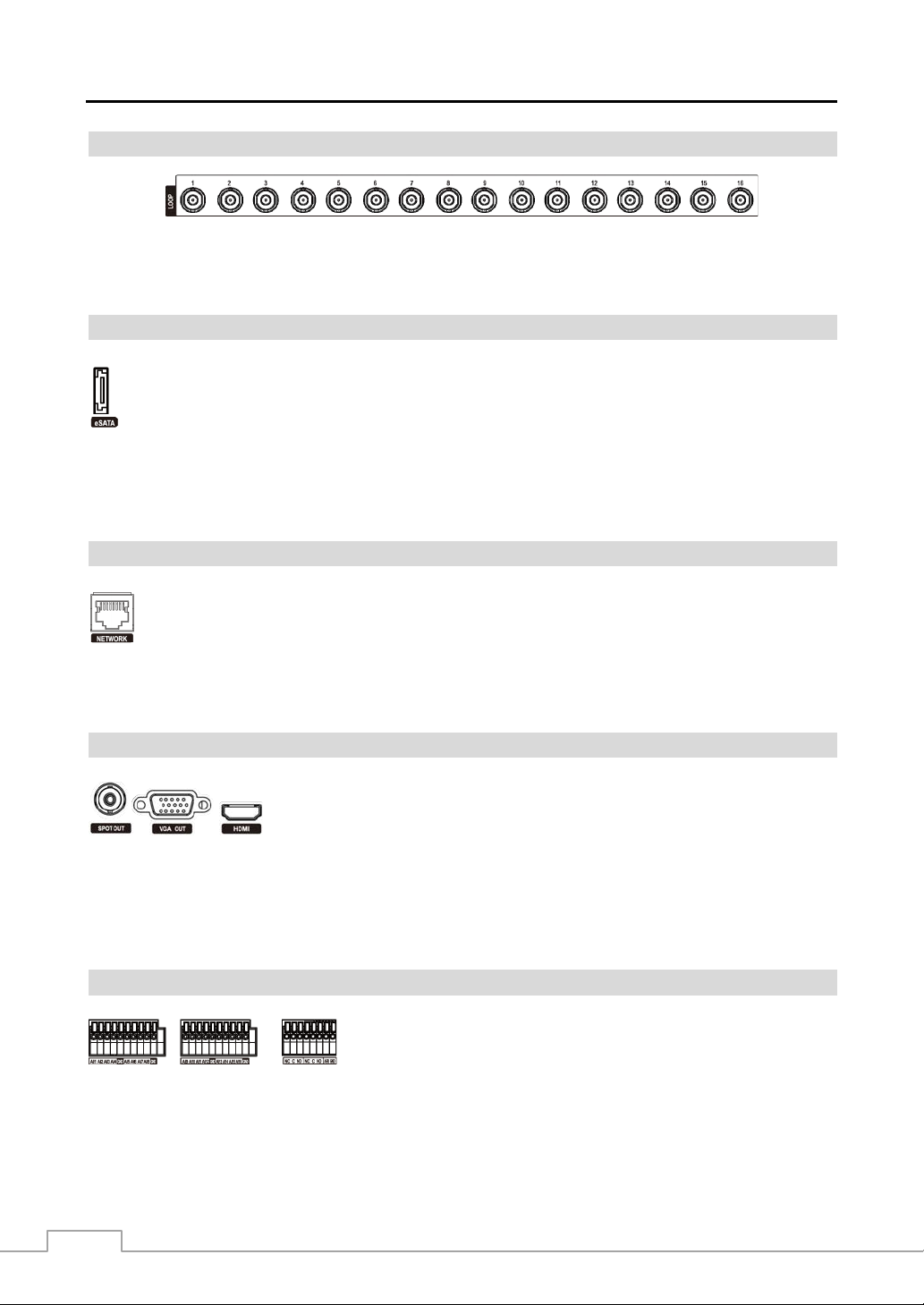
Figure 2 : 16-Channel DVR rear panel.
Factory Reset Switch RS485 Port
Power Cord Connector
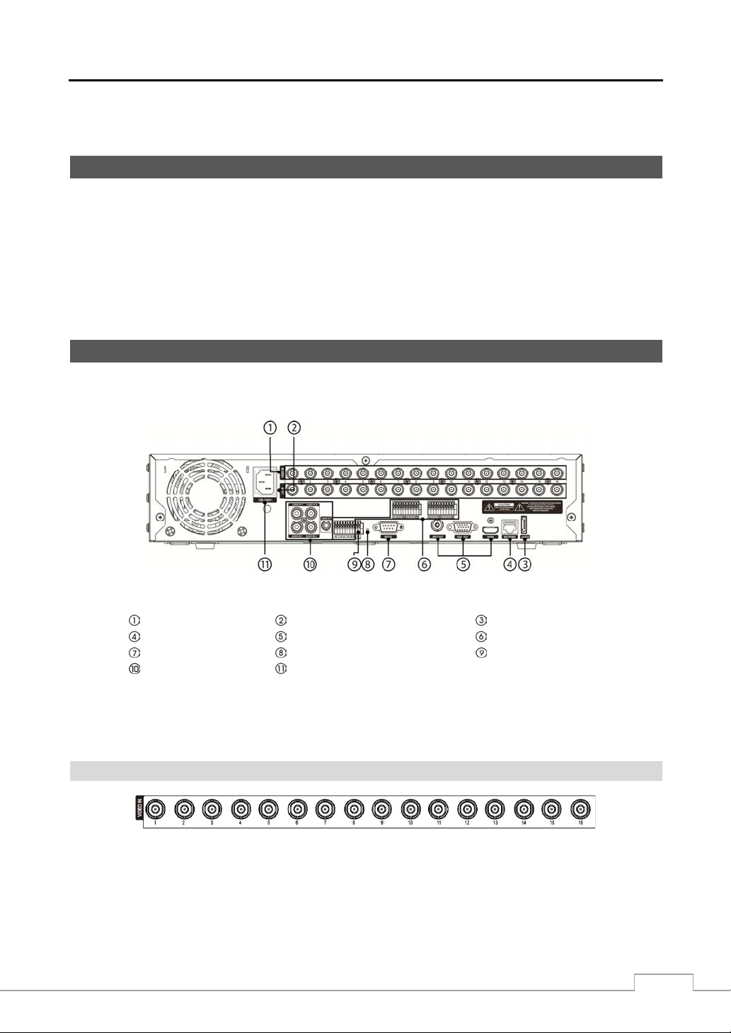
Video Input
Connect the coaxial cables from the video sources to the BNC Video In connectors.
3
Page 12
Operation Instruction
A
Video Loop Through
If you would like to connect your video source to another device, you can use the Loop BNC connectors.
NOTE: The Loop BNC connectors are auto terminated. Do NOT connect a cable to the Loop BNC unless it is
connected to a terminated device because it will cause poor quality video.
eSATA Port
An eSATA port is provided to connect external storage devices for recording or archiving video. Connect
the external eSATA hard disk drive (RAID) cable to the eSATA port.
CAUTION: Do NOT connect or dis conne ct eSA T
devices while the DVR power is on. The DVR must
be powered down to connect or disconnect eSATA devices. Power up eSATA devices
so they are ready for operation before powering up the DVR. Power down eSATA devices
after powering down the DVR and then disconnect eSATA devices.
Network Port
The DVR can be networked using the 10Mb/1Gb Ethernet connector. Connect a Cat5 cable with an RJ-45
jack to the DVR connector. The DVR can be networked with network cam eras or video transmitters for remote
monitoring and recording, and can also be networked with a computer for remote monitoring, searching,
configuration and software upgrades. See Chapter 3 ─ Configuration for configuring the Ethernet connections.
CAUTION: The network connector is not designed to be connected directly with cable or wire
intended for outdoor use.
Video Out
An HDMI (High-Definition Multimedia Interface) connector is provided so that you
can use an HDMI monitor as your primary monitor.
A VGA OUT connector is provided so that you can use a standard, multi-sync computer
monitor as your primary monitor. Use the cable supplied with your monitor to connect
it to the DVR.
NOTE: Connect the monitor before the DVR boots so that video can be displayed on the monitor with the resolution
you have set during system setup.
Connect the spot monitor to the SPOT OUT connector as needed.
Alarm Input/Output
AI 1 to 16 (Alarm-In): You can use external devices to signal the DVR to react to events. Mechanical or electrical
switches can be wired to the AI (Alarm-In) and GND (Ground) connectors. The threshold voltage of electrical switches
for NC (Normally Closed) is above 2.4V and for NO (Normally Open) is below 0 .3V, and should be stable at least 0.5
seconds to be detected. The voltage range of alarm input is from 0V to 5V. See Chap ter 3 ─ Configuration f or configuring
alarm input.
NOTE: To make connections on the Alarm Connector Strip, press
and hold the button and insert the wire in the hole below the button.
After releasing the button, tug gently on the wire to make certain it
is connected. To disconnect a wire, press and hold the button above
the wire and pull out the wire.
4
Page 13
Digital Video Recorder
y
GND (Ground): Connect the ground side of the Alarm input and/or alarm output to the GND connector.
NOTE: All the connectors marked GND are common.
NC/NO (Relay Alarm Outputs): The DVR can activate external devices such as buzzers or lights. Connect the device
to the C (Common) and NC (Normally Closed) or C and NO (Normally Open) connectors. NC/NO is a relay output
which sinks 2A@125VAC and 1A@30VDC. See Chapter 3 ─ Configuration for configuring alarm output.
ARI (Alarm Reset In): An external signal to the Alarm Reset In can be used to reset both the Alar m Out signal and
the DVR’s internal buzzer. Mechanical or electrical switches can be wired to the ARI (Alarm Reset In) and GND (Ground)
connectors. The threshold voltage is below 0.3V and should be stable at least 0.5 seconds to be detected. Connect the
wires to the ARI and GND connectors.
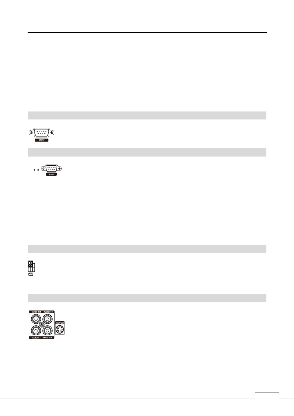
RS232C Port
An RS232 port is provided to connect a remote control keyboard.
Factory Reset Switch
The DVR has a Factory Reset switch to the left of the RS232 connector on the rear panel. This
switch will only be used on the rare occasions that you want to return all the settings to the original
factory settings.
CAUTION: When using the Factor
Reset, you will lose any settings you have saved.
To reset the unit, you will need a straightened paperclip:
1. Turn the DVR off.
2. Turn it on again.
3. While the DVR is initializing, the front panel LEDs will blink. When the front panel LEDs blink, poke the
straightened paperclip into the unlabeled hole to the left of the RS232 connector.
4. Hold the switch until the DVR’ internal buzzer sounds twice.
5. Release the reset switch. All of the DVR’s settings are now at the original settings it had when it left the factor y.
RS485 Port
The DVR can be controlled remotely by an external device or control system, such as a control keyboard,
using RS485 half-duplex serial communications signals. The RS485 connector can also be used to control
PTZ (pan, tilt, zoom) cameras. Connect RX+/TX+ and RX-/TX- of the control system to the + and –
(respectively) of the DVR. See Chapter 3 ─ Configuration and the PTZ camera or remote controller
manufacturer’s manual for configuring the RS485 connection.
Audio In/Out
Your DVR can record audio from up to four sources. Connect the audio sources to Audio In 1,
Audio In 2, Audio In 3 and Audio In 4 as needed using RCA jacks. Connect Audio Out to
your amplifier.
NOTE: It is the user’s responsibility to determine if local laws and regulations permit recording audio.
The DVR does not have amplified audio output, so you will need a speaker with an amplifier. The DVR
does not have a pre-amplifie r for audio in put, so the a udio in put shou ld b e from a n ampl ified source, not
directly from a microphone.
5
Page 14

Operation Instruction
Power Cord Connector
Connect the AC power cord to the DVR and then to a wall outlet.
WARNING: ROUTE POWER CORDS SO THAT THEY ARE NOT A TRIPPING HAZARD. MAKE
CERTAIN THE POWER CORD WILL NOT BE PINCHED OR ABRADED BY FURNITURE.
DO NOT INSTALL POWER CORDS UNDER RUGS OR CARPET.
THE POWER CORD HAS A GROUNDING PIN. IF YOUR POWER OUTLET DOES NOT
HAVE A GROUNDING PIN RECEPTACLE, DO NOT MODIFY THE PLUG. DO NOT
OVERLOAD THE CIRCUIT BY PLUGGING TOO MANY DEVICES IN TO ONE CIRCUIT.
Your DVR is now ready to operate. Refer to Chapter 3 ─ Configuration and Chapter 4 ─ Operation.
6
Page 15
Digital Video Recorder
Chapter 3 — Configuration
NOTE: Your DVR should be completely installed before proceeding. Refer to Chapter 2 — Installation.
Front Panel Controls
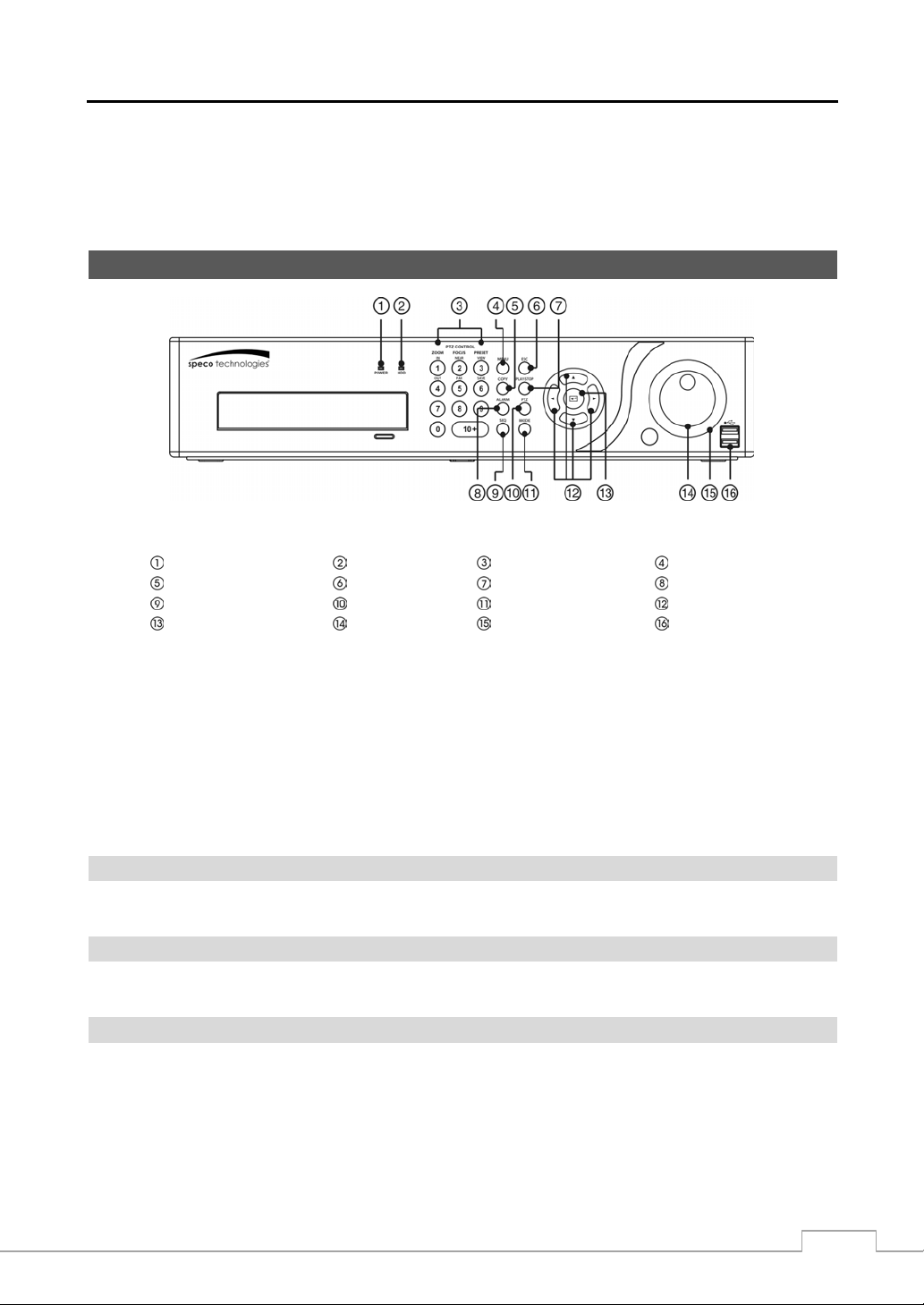
Figure 3 : 16-Channel DVR front panel.
Power LED HDD LED Camera Buttons Menu Button
Copy Button Esc Button Play/Stop Button Alarm Button
Sequence Button PTZ Button Mode Button Arrow Buttons
Enter Button Jog Dial Shuttle Ring USB Port
The front panel looks and operates much like a VCR combined with a multiplexer. The following describes each button
and control. Take a few minutes to review the descriptions. You will use these to initially set up your DVR and for
daily operations.
NOTE: The infrared sensor on the DVR is just to the left of the Jog Dial. Make certain that nothing blocks the
sensor, or the remote control will not function properly.
When you use wireless communication devices (such as Wi-Fi or Bluetooth) near the DVR, the remote
control might not function properly.
You can also use a USB mouse (not supp lied) to nav igate through the s creens and menus m uch like y ou
would on a computer.
Power LED
The POWER LED is lit when the unit is On.
HDD LED
The HDD LED flickers when the DVR is recording or searching video on the hard disk drive.
Camera Buttons
Pressing the individual camera buttons will cause the selected came ra to display full screen. Pressing the buttons 1 to
4 toggles the camera selection between local cameras and network cameras. For example, pressing the button 1 displays
the local camera number 1 and pressing the button 1 again displays the network camera number 1. Buttons are also
used to enter passwords.
NOTE: When selecting the camera channel from 10 to 16, press the 10+ and then 0 to 6.
7
Page 16
Operation Instruction
In the PTZ mode, pressing the button 1 zooms in the screen and the button 4 zooms out the screen, pressing the button
2 focuses near and button 5 focuses far, and pressing the button 3 moves to the preset and button 6 saves the preset.
Menu Button
In the Live Monitoring mode and Search mode, pressing the MENU button displays the menu icons to the right edge
of the screen.
Copy Button
Pressing the
COPY button allows you to copy video clips.
Esc Button
During menu setup, pressing the
ESC button closes the current menu or setup dialog box.
Play/Stop Button
Pressing the
entering the playback mode, video is paused.
PLAY/STOP button enters the playback mode, and pressing the button again exits the playback mode. When
When in one of the multi-view formats, pressing this button enters the Triplex mode. The DVR supports the Triplex
function: monitoring, recording and playing back at the same time.
Alarm Button
ALARM button has two functions. First, it will reset the DVR’s outputs including the internal buzzer during an
The
alarm. Second, it will display the event log when you are in the live monitoring mo de unless there is an active alarm.
This operation can be user password protected.
Sequence Button
When in the live mode, pressing the SEQ button displays live channels sequentially.
PTZ Button
Pressing the PTZ button enters the PTZ (Pan/Tilt/Zoom) mode and the PTZ icon flickers. Pressing the button again
exits the PTZ mode. Pressing the arrow buttons or MENU button allows you to control properly configured cameras.
Mode Button
Pressing the
MODE button toggles between different display formats. The available formats are: PIP, 2x2, 3x2, 3x3,
4x3, 4x4 or 5x4.
Arrow Buttons
These buttons are used to navigate through menus and GUI. You can also use them to change numbers by highlighting
a number in the menu and using the Up and Down arrow buttons to increase or decrease the number’s value.
These buttons are also used to control Pan and Tilt when in the PTZ mode. When in the PIP display format, pressing
the Up and Down arrow buttons moves the position of the small screen counter-clockwise and clockwise, and pressing
the Left and Right buttons moves through screen pages.
8
Page 17
Digital Video Recorder
Enter Button
The
(Enter) button selects a highlighted item or completes an entry that you have made during system setup.
Jog Dial
When in the playback mode, you can play video forward image-by-image by turning the Jog Dial clockwise and backward
image-by-image by turning the Jog Dial counterclockwise. When in the PIP mode, you can make the PIP screen smaller
by turning the Jog Dial clockwise and larger by turning the Jog Dial counterclockwise. When in the Setup mode, you
can change number values by highlighting the item in the menu and turning Jog Dial clockwise or counterclockwise
to increase or decrease the number.
Shuttle Ring
The Shuttle Ring only functions in the Playback mode. The Shuttle Ring is spring loaded and returns to the center position
when released. Turning the ring clockwise plays video forward. Turning the ring counterclockwise plays video backward.
Playback speed varies with the amount the ring is turned. The playback speeds are
and
. When you release the ring, it snaps back to the center position and the video pauses.
, , , x0.5, , ,
USB Port
Two USB ports on the front panel are provided to connect external hard disk or flash drives for video clip copying or
system upgrades. Position external drives close enough to the DVR so that you can make the cable connections, usually
less than 6 feet. Use the USB cable provided with the hard disk drive to connect it to the DVR.
A USB mouse (not supplied) can be connected to one of the ports. You can use the mouse to navigate through the
screens and menus much like you would on a computer.
A PostScript™ USB printer (not supplied) can be connected to one of the ports. You can print selected images resulting
from a search. Refer to Chapter 4 — Operation, Searching Video.
A USB to Serial converter can be connected to the USB port. Multiple text-in devices can be used with a USB to Serial
converter.
9
Page 18
Operation Instruction
Remote Control Buttons
ID Button
Camera Buttons
Sequence Button
Login/Logout Button
Arrow Buttons
Menu Button
Playback Buttons
Alarm Button
Layout Button
Zoom Button
PTZ Button
Enter Button
Esc Button
PTZ Control Buttons
Copy Button
Play/Stop Button
Figure 4 : Infrared remote control.
NOTE: For simplicity, the button descriptions in this manual refer to the front panel buttons.
ID Button
If a DVR System ID is set to 0, the infrared remote control will control that DVR without any additional operations.
(Refer to the System General setup screen in this chapter for further information on setting the System ID.) If the system
ID is 1 to 16, you must to press the ID button and then press the number button (1 to 16 (+10 & 6)) in order to control
that DVR. If the System ID of two or more DVRs is set to 0, those DVRs will react to th e infr ared rem ote contro l at
the same time.
Camera Buttons
Pressing the individual camera buttons will cause the selected camera to display full screen. Buttons 1 to 9 are also
used to enter passwords.
Sequence Button
When in the Live Monitoring mode, pressing the SEQUENCE button displays live channels sequentially.
Login/Logout Button
Pressing the
LOGIN/OUT button displays the Login or Logout screen.
10
Page 19
Digital Video Recorder
Arrow Buttons
These buttons are used to navigate through menus and GUI. You can also use them to change numbers by highlighting
a number in the menu and using the Up and Down arrow buttons to in cre as e or decrease the number’s value. These
buttons are also used to control Pan and Tilt when in the PTZ mode.
Menu Button
In the Live Monitoring mode and Search mode, pressing the
of the screen.
MENU button displays the menu icons to the right edge
Playback Buttons
Rewind: Pressing the button plays video backward at high speed. Pressing the button again toggles the playback
speed from
Play/Pause: Pressing the
The screen displays
video.
Fast Forward: Pressing the
playback speed from
Stop: Pre ssing the button stops playback and enters the Live Monitoring mode.
Backward: Wh en in the pause mode, pressing the button moves to the previous image.
Forward: When in the pause mode, pressing the button moves to the next image.
In the Live Monitoring mode, pressing any playback button enters to the Search mode.
, and .
button plays back video at regular speed and pressing the button again pauses video.
when the DVR is in the Pause mode and the screen displays when the DVR is playing back
button plays video forward at high speed. Pressing the button again toggles the
, and .
Alarm Button
Pressing the
ALARM button resets the DVR’s outputs including the internal buzzer during an alarm.
Layout Button
Pressing the LAYOUT button toggles between different display formats. The available formats are: 5x4, 4x4, 4x3, 3x3,
3x2, 2x2 and PIP.
Zoom Button
Pressing the ZOOM button zooms the current image on the screen. A PIP with a rectangle temporarily displays showing
what area of the screen has been enlarged. You can use the arrow buttons to move the rectangle to another area.
PTZ Button
Pressing the PTZ button enters the PTZ (Pan/Tilt/Zoom) mode which allows you to control properly configured cameras.
Enter Button
The
(Enter) button selects a highlighted item or completes an entry that you have made during system setup.
Esc Button
During menu setup, pressing the ESC button closes the current menu or setup dialog box.
11
Page 20
Operation Instruction
PTZ Control Buttons
While in the PTZ mode, the PRESET buttons are used to save Presets and load a Preset View, the ZOOM buttons are used
to Zoom In and Zoom Out, and the FOCUS buttons are used for Near Focus and Far Focus.
Copy Button
Pressing the
COPY button allows you to copy video clips.
Play/Stop Button
Pressing the PLAY/STOP button enters the playback mode, and pressing the button again exits the playback mode. When
entering the playback mode, video is paused. Pressing the button plays back video at regular speed. The screen
displays
when the DVR is in the Pause mode and the screen displays when the DVR is playing back video.
When in one of the multi-view formats, pressing this button enters the Triplex mode. The DVR supports the Triplex
function: monitoring, recording and playing back at the same time.
Turning on the Power
Connecting the power cord to the DVR turns on the unit. The unit takes approximately 60 seconds to initialize.
Initial Unit Setup
Before using your DVR for the first time, you will want to establish the initial settings. This includes items such as
time and date, display language, camera, remote control, r ecord mode, network an d password. Your DVR can be set
up using various screens and dialog boxes.
Throughout the screens you will see
reset that screen to its default settings. After you are finished with any setup screen, you can highlight Save and press
the
button to save the changes and exit the screen. If you do not wish to save the changes, highlight Cancel and
press the
button to exit the screen.
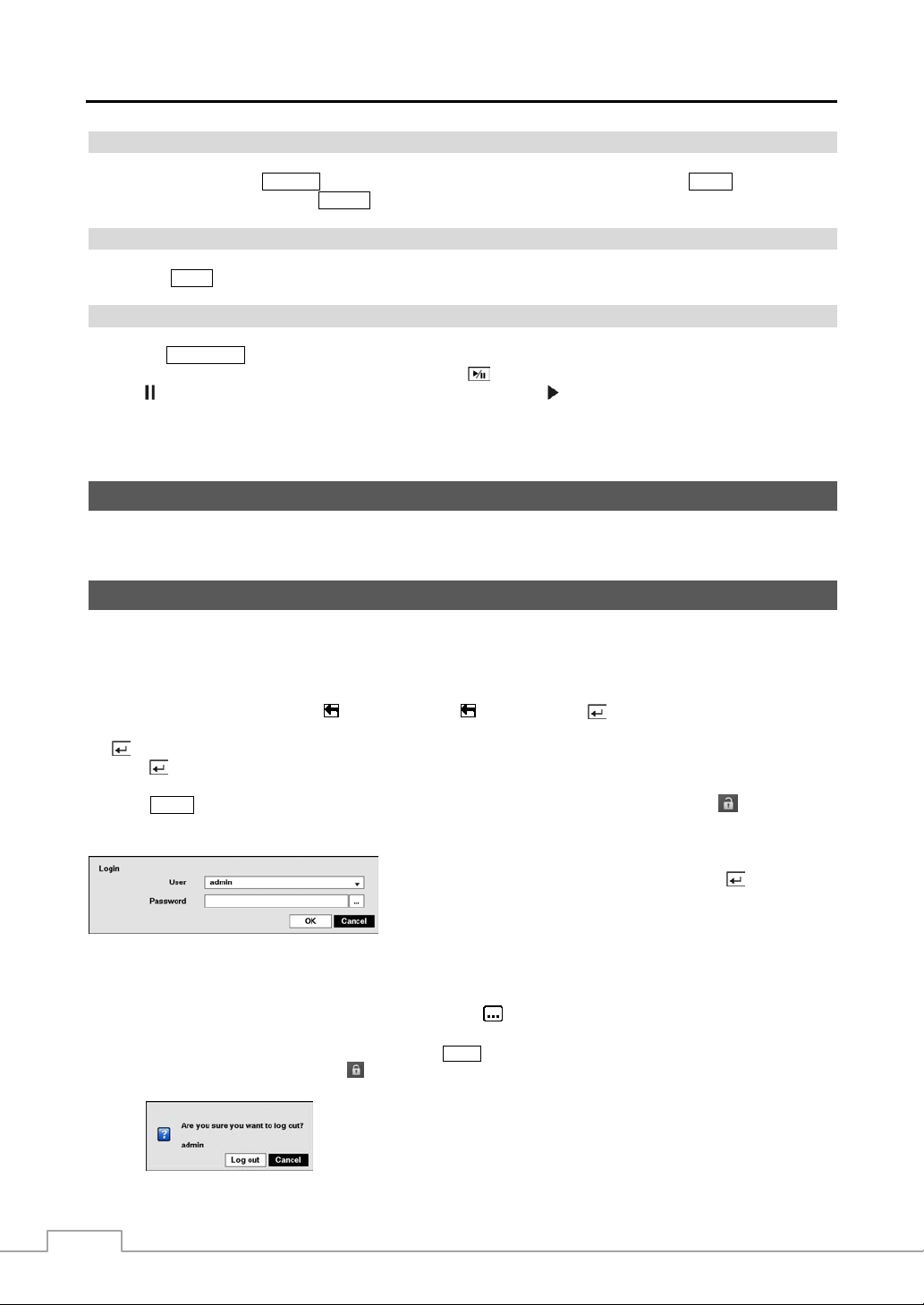
Press the MENU button or move the mouse pointer on the right edge of the screen and then select (Login) in the
Live Monitoring menu to enter the setup screens. The Login screen appears.
Figure 5 : Login screen.
NOTE: To assure the secure management of the system, setting up a password is strongly recommended.
If you cannot use the front panel but ton s, c li ck the
the virtual keyboard displays. See instructions below for using the virtual keyboard.
To log the user out of the system, press the
of the screen and then select (Logout) in the Live Monitoring menu. The Logout screen displays
asking you to confirm whether or not you want to log out the current user.
. Highlighting the and pressing the button gives you the opportunity to
Select a User and enter the password by pressing the appropriate
combination of Camera number buttons and then the
button. There
is no default password when logging in the admin user for the first
time.
button using the mouse to enter a password, and
MENU button or move the mouse pointer on the right edge
12
Figure 6 : Logout screen.
Page 21
Setup Screen
Digital Video Recorder
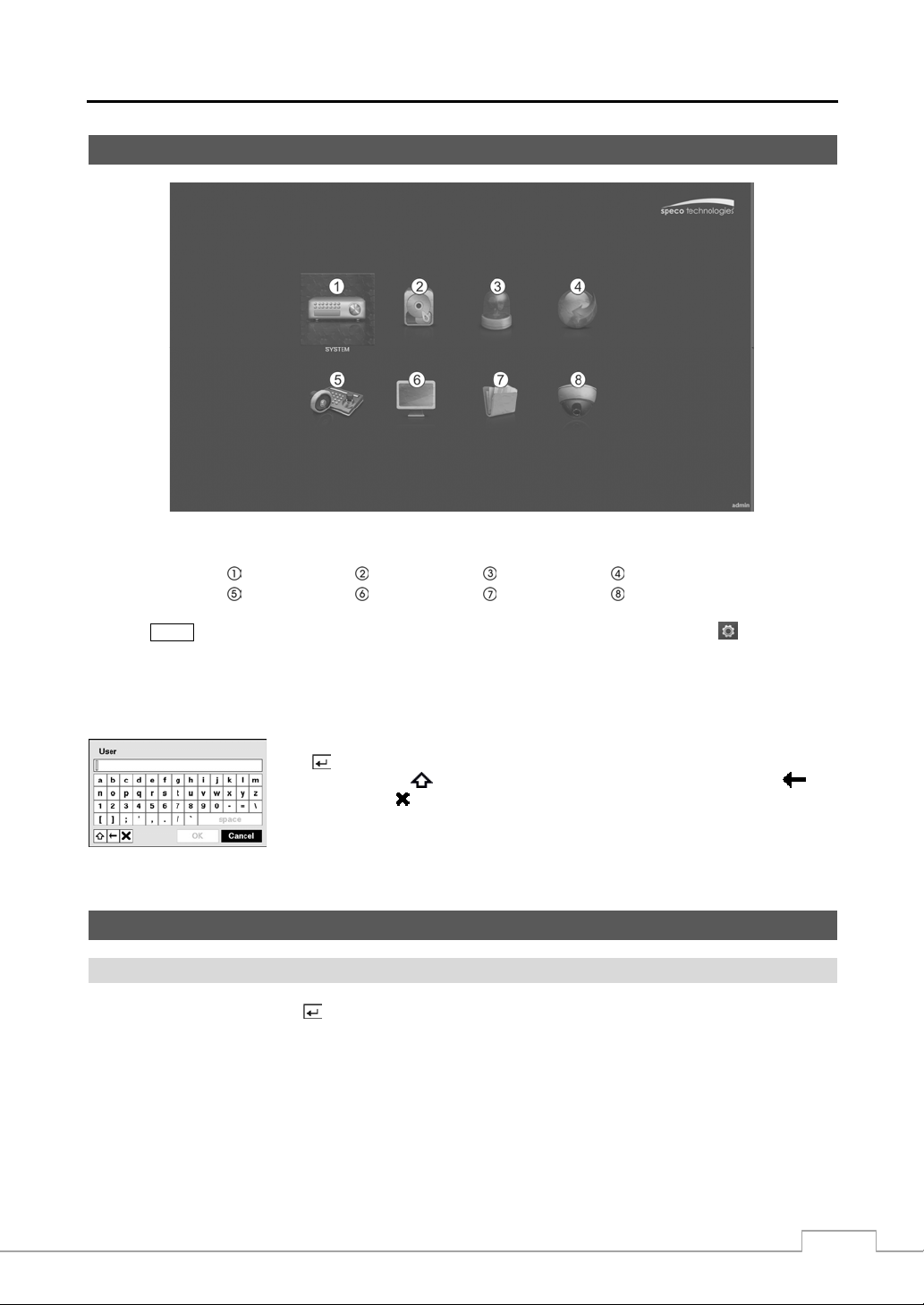
Figure 7 : Setup screen.
System Record Event Network
Device Display Status Camera
Press the
MENU button or move the mouse pointer on the right edge of the screen and then select (Setup) in the
Live Monitoring menu to enter the setup screen.
While setting up the DVR, there will be many opportunities to enter names and titles. When making these entr ies, a
Virtual Keyboard will appear.
Use the arrow keys to highlight the character you want in the name or title and press
the
button. That character appears in the title bar and the cursor moves to the next
position. Pressing
backspaces, and
toggles between the upper and lower case keyboards,
deletes entered characters.
Special characters can be created using ^ and a capital letter; e.g., ^J for NL (New Line),
^M for CR (Carriage Return). Special ch aracters ar e commonly us ed by text inp ut devices
and will be useful when performing Text-In Searches.
System Setup
General
Highlight General and press the button, and the General screen appears.
13
Page 22
Operation Instruction
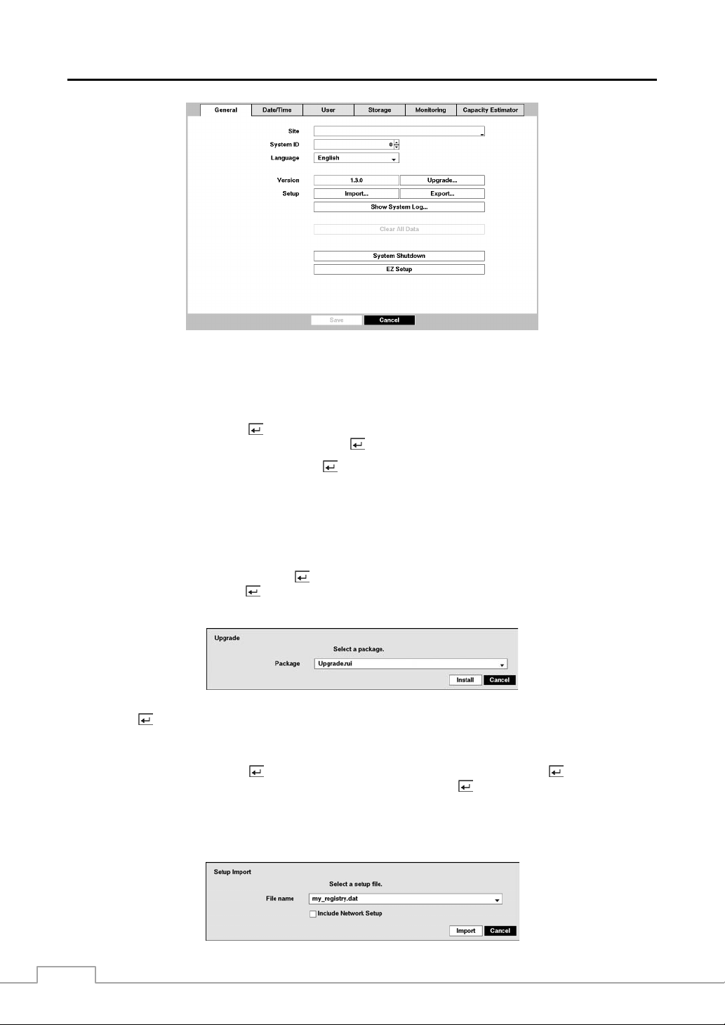
Figure 8 : System – General setup screen.
In the General screen, you can name the site loc ation, assign a S ystem ID number, select th e language the screens are
displayed in, display software version number, upgrade the software, show the System Log, display recorded time data,
and clear all data.
Highlight the Site box and press the button. A virtual keyboard appears that you can use to enter a Site Name. Once
you have entered your title, highlight OK and press the
button.
Highlight the box beside System ID and press the button. Change the number by highlighting it and using the Up
and Down arrow buttons to increase and decrease the number from 0 to 99.
NOTE: The System ID number is used to identify the unit when it is connected with other DVRs through the
Highlight the box beside Language and press
the desired language and press the
The box beside Version displays the software version of the DVR.
RS485 port. You cannot use the same ID number for two or more DVRs that are in the same RS485
network. It is possible to have multiple DVRs with System ID 0 that are in the same area as long as they
are not part of an RS485 network. If this is the case, all will be controlled at the same time when using
the infrared remote control.
button. A drop-down menu displays the available langu ages. Highligh t
button.
To upgrade the software, connect a USB device containing the upgrade package file to the DVR. Highlight Upgrade…
and press the
button. The Upgrade screen appears. The screen displays the upgr ade packag e file names that are
available. The “.rui” indicates that the file is for software upgrades and “.ofi” indicates that the file is for optical drive
firmware upgrades.
Select the desired file and press the button. Highlighting the Install button and pressing the button will install
the selected software package. Highlighting the Cancel button and pressing the
button will close the window without
upgrading the software. If the upgrade package file is not installed on the DVR properly, you will get an error message.
The system restarts automatically after completing the upgrade.
CAUTION: The USB device must be FAT16 or FAT32 format.
14
Page 23
Digital Video Recorder
You can import saved DVR settings or export the current DVR settings. To import saved DVR settings, connect the
USB device containing the setup file (.dat) to the DVR. Highlight Setup – Import… and press the
button. Select
the desired setup file and press the Import button to import the selected settings and change the DVR settings accordingly.
Highlight Include Network Se tup and press the
settings will not be changed.
button to toggle between On and Off. When set to Off, the network
To export the current DVR settings, connect the USB device to the DVR. Highlight Setup – Export… and press the
button. Highlight the box beside File name and press the button. A virtual keyboard allows you to enter the
file name. Selecting Export will save the current settings in .dat file format on the USB device.
NOTE: Even after changing the DVR settings by importing saved settings, the time-related settings (D ate /T im e,
Time Zone and Daylight Saving Time) will NOT be changed.
CAUTION: The USB device must be FAT16 or FAT32 format.
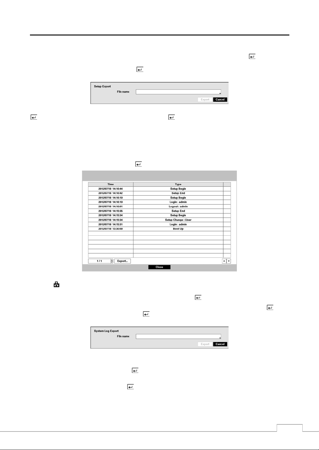
Highlight Show System Log… and press the button to display the System Log.
The System Log screen lists system activities (up to 5,000 from the latest) that have occurred along with the time and
date. The icon will be displayed in the last column for s ystem activities of the r emote site. You can scrol l through
the log pages by using the Up and Down arrows, or you can go directly to a log page by entering the log page number
in the box at the bottom left of the screen. Highlight Close and press the
button to exit the screen.
To export the system log information, connect the USB device to the DVR. Highlight Export… and press the button.
Highlight the box beside File name and press the
Selecting Export will save the log information in .txt file format on the USB device.
button. A virtual keyboard allows you to enter the file name.
NOTE: When opening the saved .txt file, setting to the proper character encoding and using fixed width fonts
will be required to read the file properly.
Highlighting Clear All Data and pressing the button will clear all video data. You will be asked to verify that you
wish to clear all data before the DVR erases the video data. Clear All Data will not clear the System Log.
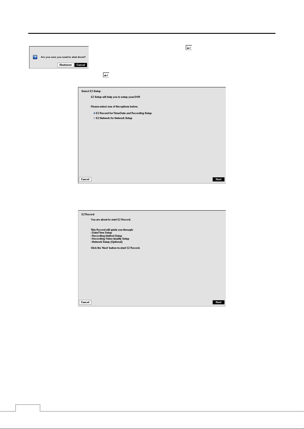
Highlight System Shutdown and press the button. The Shutdown screen displays asking you to confirm whether
or not you want to shut the system down.
15
Page 24
Operation Instruction
After selecting Shutdown and pressing the
button, a screen will appear telling you
when it is safe to disconnect power.
Highlight EZ Setup and press the button. The EZ Setup screen appears and guides you through configuring the
system for basic operation.
Select either EZ Record or EZ Network and select the Next button to start the selected setup.
NOTE: Selecting the Cancel button throughout the screens exits the EZ Setup without saving your changes
If you selected the EZ Record, selecting the Next button starts the EZ Record.
and returns to the System – General setup screen.
16
Page 25
Digital Video Recorder
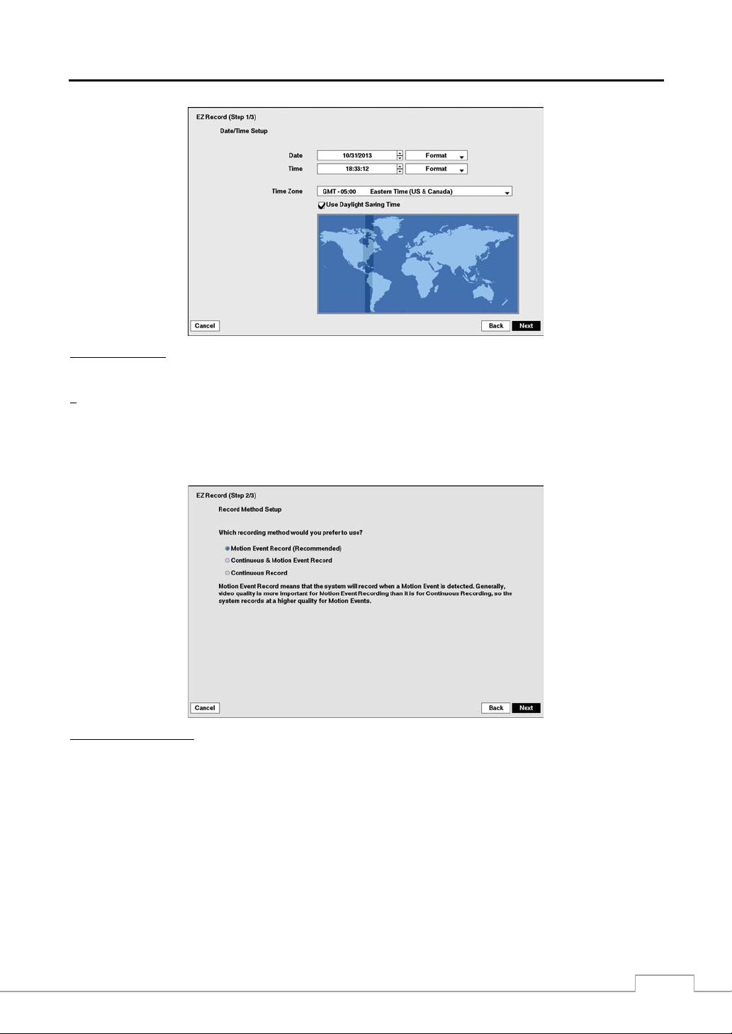
Date/Time Setup
Date: Set the system date and select the date format.
Time: Set the system time and select the time format.
Time Zone: Select your time zone.
Use Daylight Saving Time: Selecting the box sets the system to use daylight saving time.
NOTE: The Date/Time will be set, and the clock will start when you click the Next button.
Record Method Setup
The Time Zone can also be selected on the map belo w by press ing the Left and Right buttons or sc rolling
the mouse wheel up and down.
Select the desired recording mode from:
– Motion Event Record (Recommended)
– Continuous & Motion Event Record
– Continuous Record
NOTE: You should understand each recording mode before setting the DVR’s recording method.
17
Page 26
Operation Instruction
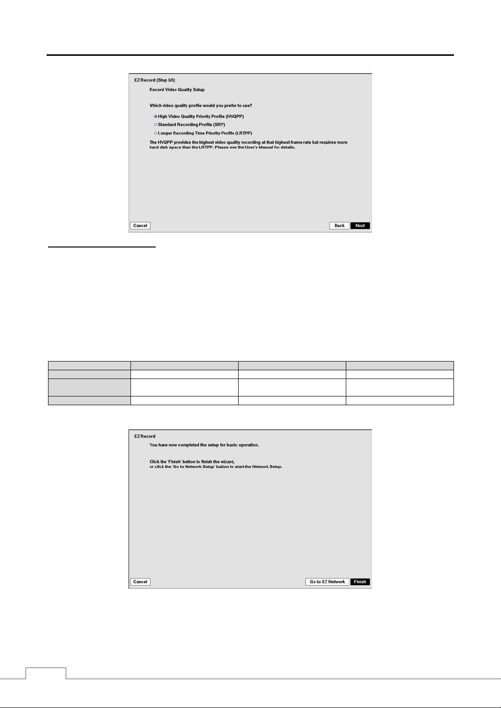
Record Video Quality Setup
Select the desired video quality profile from:
– Higher Video Quality Priority Profile
– Standard Recording Profile
– Longer Recording Time Priority Profile
NOTE: The higher quality setting requires more storage space.
The recording resolution will be set to Very High when selecting High Video Quality Priority Profile, High
when selecting Standard Recording Profile, and Standard when selecting Longer Recording Time Priority
Profile.
The recording quality and recording speed of each camera channel will be set as show below according
to the Record Method and Record Video Quality you s et.
HVQPP* SRP* LRTPP*
Motion Event Record Very High / 30 ips High / 5 ips Standard / 3 ips
Continuous &
Motion Event Record
Continuous Record Very High / 30 ips High / 5 ips Standard / 3 ips
* Record Video Quality: HVQPP (High Video Quality Priori ty Profile), SRP (S tandard Recording Pro file), LRTPP (Longer Recording Time
Priority Profile)
Very High / 30 ips (Time)
Very High / 30 ips (Event)
High / 5 ips (Time)
Very High / 30 ips (Event)
Standard / 3 ips (Time)
High / 5 ips (Event)
Select the Finish button to finish the EZ Record and select the Go to EZ Network button to start the EZ Network.
18
Page 27
Digital Video Recorder
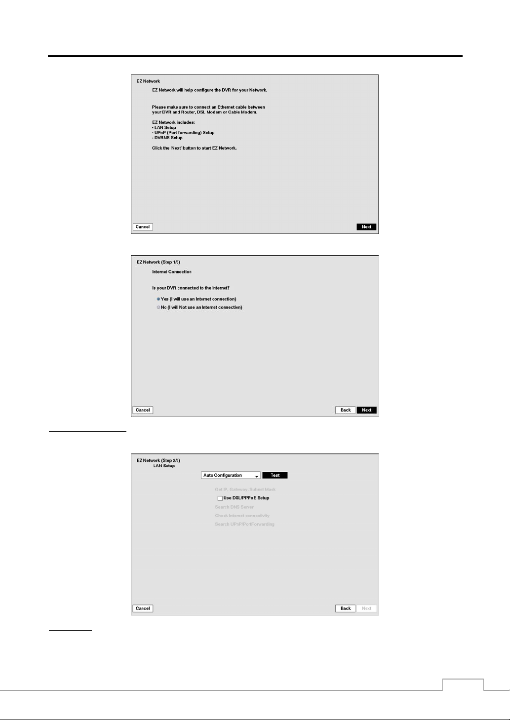
If you selected the Go to EZ Network, select the Next button to start the EZ Network.
Internet Connection
Select whether or not your DVR is connected to the Internet.
LAN Setup
Select between Auto Configuration and Manual Configuration for network configuration, and then select the Test
button to test the network configuration you selected.
19
Page 28
Operation Instruction
NOTE: Selecting Auto Configuration allows the DVR to automatically obtain LAN parameters (IP address, Gateway,
Subnet Mask and DNS Server address). Selecting Manual Conf igurati on allows you to set up LAN
parameters manually.
The network configuration you set should be tested by selecting Test, otherwise the Next button will
cannot be selected, and you cannot move to the next step.
Use DSL/PPPoE Setup: Selecting the box allows you to set up the DSL network. Entering the ID and password
for DSL connection is required.
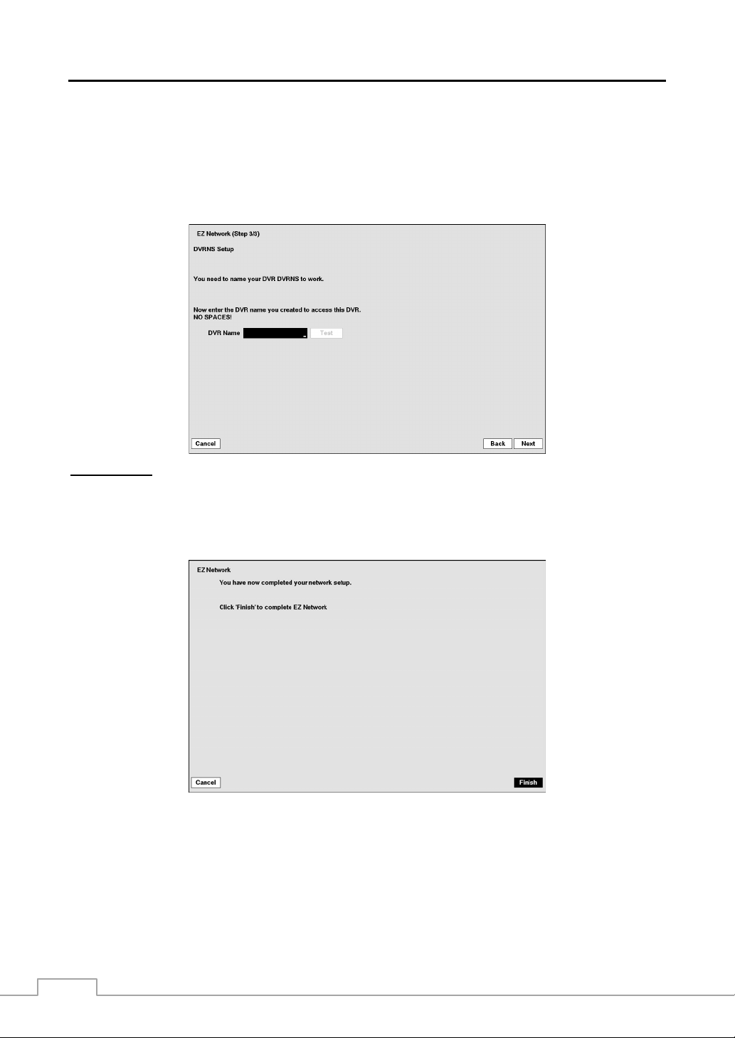
DVRNS Setup
DVR Name: Enter the DVR name to be registered on the DVRNS server.
NOTE: The DVR Name you entered should be checked by selecting Test, otherwise the DVRNS changes will
not be saved.
Select the Finish button to finish the EZ Setup.
When entering no name or a name already registered on the DVRNS server, an error message displays.
20
Page 29
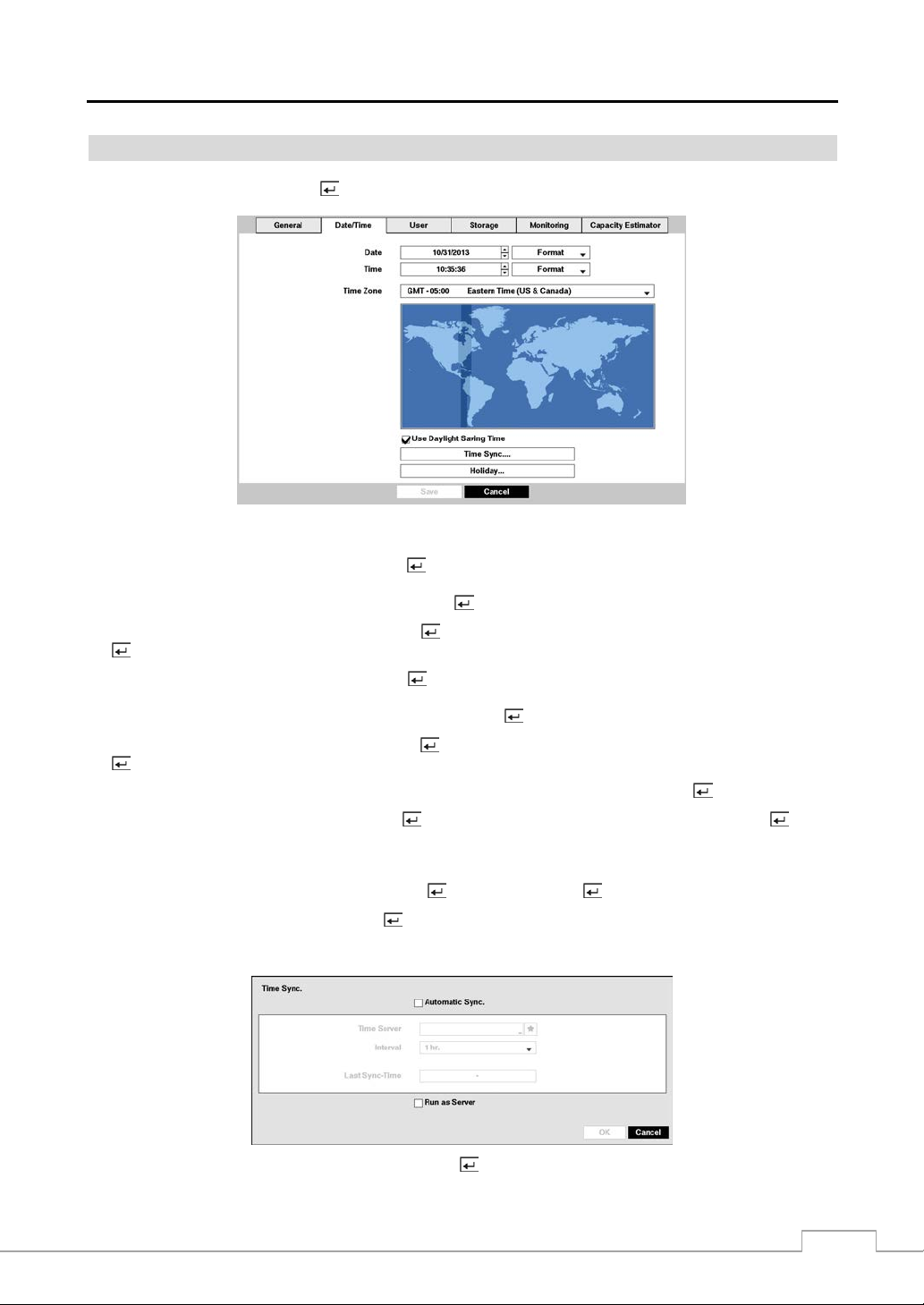
Date/Time
Highlight Date/Time and press the button, and the Date/Time setup screen appears.
Digital Video Recorder
Figure 9 : System – Date/Time setup screen.
Highlight the first box beside Date and press the
button. The individual sections of the date will highlight. Use
the Up and Down arrow buttons to change the number. Use the Left and Right arrow buttons to move between month,
date and year. Once you have the correct date, press the button.
Highlight the Format box beside Date and press the button. Select from the three available date formats and press
the
button to save your selected format.
Highlight the first box beside Time and press the button. The individual sections of the time will highlight. Use
the Up and Down arrow buttons to change th e number. Use the Left and Right arrow buttons to move between hour,
minutes and seconds. Once you have the correct time, press the button.
Highlight the Format box beside Time and press the button. Select from the three available time formats and press
button to save your selected format.
the
NOTE: The clock will not start running until you have highlighted Save and pressed the button.
Highlight the box beside Time Zone and press the button. Select your time zone from the list and press the button.
NOTE: The Time Zone can also be selected on the m ap belo w by pressing the Left and Right buttons o r scrol ling
Highlight Use Daylight Saving Time and press the button. Pressing the button toggles between On and Off.
the mouse wheel up and down.
Highlighting Time Sync.… and pressing the button displays the Time Sync. screen. You can set up time
synchronization between the DVR and standard time servers that are available in most time zones and countries, or
between the DVR and another DVR.
Highlight the box beside Automatic Sync. and press the button. This toggles between On and Off.
21
Page 30
Operation Instruction
Highlight the box beside Time Server and press the
the IP address or domain name of the time server. Highlighting
registered time servers.
NOTE: You can use the domain name instead of IP address if you already set up the DNS Server when setting
up the Network – IP Address.
button. A virtual keyboard appears that you can use to enter
allows you to select your time server from a list of
Highlight the box beside Interval and press the button. Set the time interval for synchronization from 30 minutes
to 1 day at various time intervals.
Last Sync-Time displays the last time the DVR was synchronized with the time server.
Highlight Run as Server and press the button. Pressing the button toggles between On and Off. When it is
On, the DVR you are setting up will run as a time server.
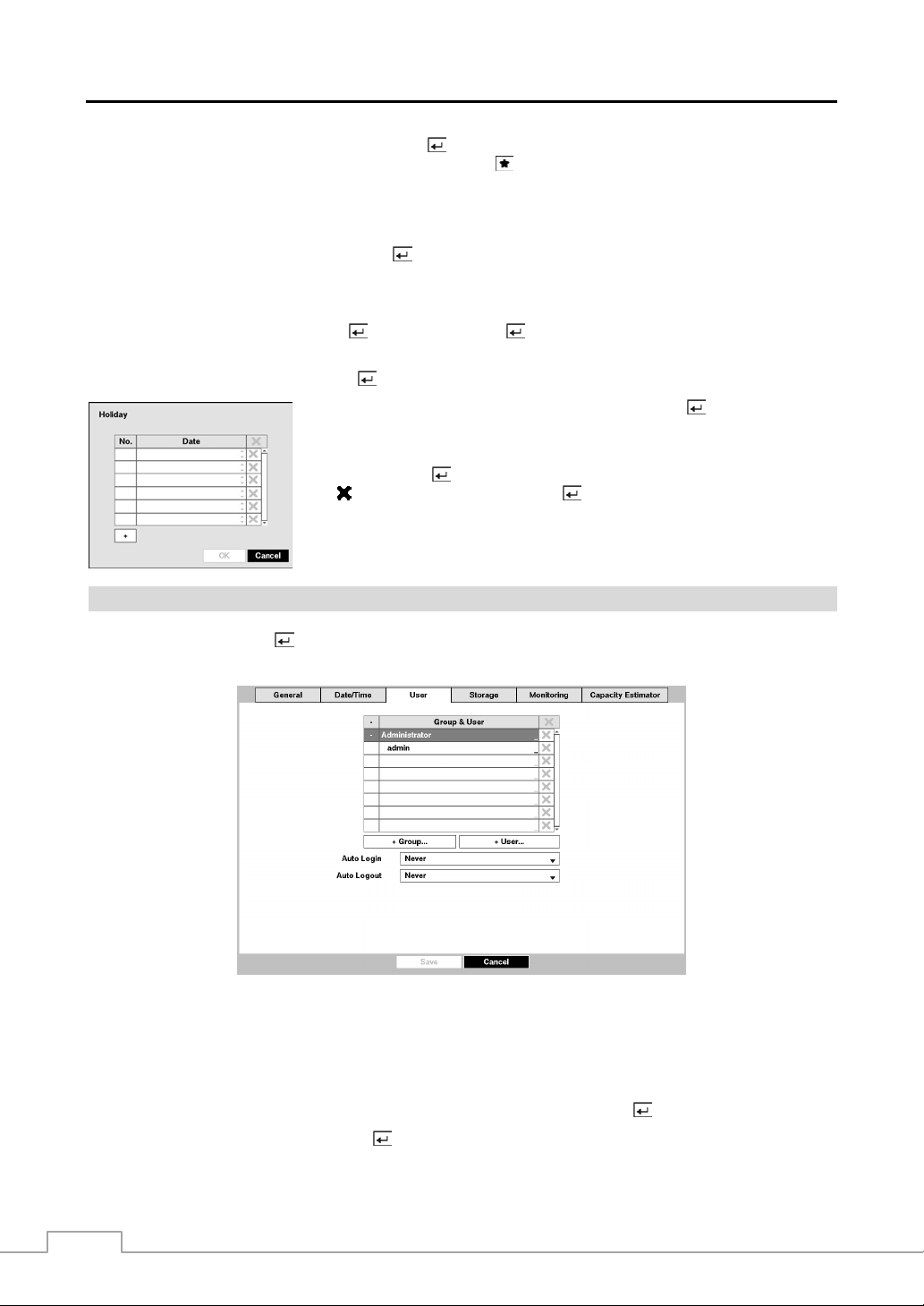
Highlighting Holiday… and pressing the button displays the Holiday screen.
You can set up holidays by highlighting + and pressing the
date appears.
button. The current
Highlight the month and day and change them by using the Up and Dow n arrow
buttons. Press the
beside the date and pressing the button.
the
NOTE: Holidays that do not fall on the same date each year should be updated
once the current year’s holiday has passed.
button to add the date. Dates can be deleted by highlighting
User
Highlight User and press the
and delete groups and users. When adding a group, you can assign authority levels to the group.
button. The User setup screen displays the authorized groups and users. You can add
Figure 10 : System – User setup screen.
The +/– column is used to collapse and expand user groups. If ther e is a + or – in th is column, it indi cates the item is
a Group Name. If there is a – in front of the Group Name, it indicates that the group has been “expanded” and all of
the User Names within that group are displayed below the Group Name. If there is a + in front of the Group Nam e, it
indicates that the group has been “collapsed” and all of the User Names within that group are hidden . To collapse or
expand a group, highlight the +/– column in front of the desired group and press the
Highlighting a Group Name and pressing the
button allows you to change the authority levels assigned to the group.
button.
22
Page 31

Digital Video Recorder
CAUTION: Write down the new password and save it in a secure place. If the password is forgotten,
the unit must be reset using the Factory Reset Button and all data settings will be lost.
Highlighting a User Name and pressing the
You can also change the group to which the user is assigned.
button allows you to add or change the password assigned to that user.
The column can be used to delete a User Name or an entire Group. If the is grayed out, that Group or User cannot
be deleted. Highlight the
and press the
button. You will be asked to confirm that you want to delete the User or
Group. To delete the User currently logged into the DVR on a local system or a PC running Speco Central, log the
user out of the system first and then delete the user.
To add a Group, highlight the + Group… box and press the
button. A virtual keyboard appears allowing you to
enter the Group name. You can use up to 15 characters including spaces in the group name. Enter the name and assign
authority levels to the group.
Highlighting the Authority box and pressing the
button will toggle
between all authority levels being turned On and Off. Highlighting
the individual authority level boxes and pressing the
button will
toggle between that authority level being turned On and Off. The
authority levels that can be turned On and Off are:
Shutdown – The user can shut the system down on a local system.
Upgrade – The user can upgrade the software on a local system or a PC
running Speco Central.
Color Control – The user can control brightness, contrast, hue and saturation
for cameras on a local system or a PC running Speco Central.
System Check – The user can view the remote system status or check
PTZ Control – The user can control the PTZ camera on a local system or a PC running Speco Central.
Alarm-Out Control – The user can reset the DVR’s outputs including the internal buzzer during an alarm by pressing the
button on a local system or alarm-out control button on a PC running Speco Central.
Covert Camera View – The user can view video from cameras set as Covert while in the Live Monitoring or Search mode on
a local system or a PC running Speco Central.
Digital Deterrent Control – The user can trigger the Digital Deterrent sound manually by selecting
Live Monitoring menu and Search menu on a local system.
Search – The user can access the Search mode on a local system or a PC running Speco Central.
Clip-Copy – The user can copy video clips on a local system or a PC running Speco Central.
Setup – The user without Setup authority cannot establish any system settings excluding system shutdown and logout on a local
system or a PC running Speco Central.
System Time Change – The user can change the system date and time on a local system or a PC running Speco Central.
Data Clear – The user can clear all video data or format disks on a local system or a PC running Speco Central.
PTZ Setup – The user can establish all PTZ settings on a local system or a PC running Speco Central.
Alarm-Out Setup – The user can establish all Alarm-Out settings on a local system or a PC running Speco Central.
Covert Camera Setup – The user can establish all Covert Camera settings on a local system or a PC running Speco Central.
Record Setup – The user can establish all Record settings on a local system or a PC running Speco Central.
Digital Deterrent Setup – The user can establish all Digital Deterrent settings on a local system.
Setup Import – The user can import saved DVR settings from a local system or a PC running Speco Central.
Setup Export – The user can export the current DVR settings to a local system or a PC running Speco Central.
VNC Setup – The user can establish all VNC settings on a local system or a PC running Speco Central.
the remote system status as a batch proces s on a PC running Speco Centr al.
(Digital Deterrent) in the
To add a User, highlight the + User… box and press the
ALARM
button. A
virtual keyboard appears allowing you to enter the User Name. Enter the
name and assign the User to a Group and password. You can use camera
buttons 1 to 9 on the front panel to assign the password. The password
can be up to 8 digits. You will be asked to confirm the password.
NOTE: In addition to using the front panel buttons or the infrared remote control, you can use the virtual keyboard
to assign the password. To display the virtual keyboard click the
button using the mouse (not supplied).
Highlighting the box beside Auto Login allows you to select a User to be automatically logged in when the DVR is
powered up. It can also be set to never automatically login a user.
23
Page 32

Operation Instruction
Highlighting the box beside Auto Logout allows you to select from a l ist of t imes that the user will be autom aticall y
logged out. The options are: Never, 1 min., 3 min., 5 min., 10 min., 15 min., 20 min., 30 min. and 1 hr.
Storage
Highlight Storage and press the
storage devices.
button. The Storage setup screen appears and displays information about the DVR’s
Figure 11 : System – Storage setup screen.
The information in the Type column describes the storage device.
The capacity of the storage device is displayed in the Capacity column.
The Format column displays whether the device is used for recording (Record), archiving (Archive) or not (Not Using).
Not formatted indicates the device is not formatted. indicates when the device has temporary space set aside so
that video clips can be saved on a DVD RW.
Highlight the box in the Format column for the desired storage device and
press the button. You will be able to format the device for recording or
archiving. When selecting Not Using from Use As and highlighting the
Format button, the device will not be used for either recording or archiving.
You can also set aside space to store temporary files for CD or DVD burning
NOTE: The DVR does NOT support USB hard disk drives with a version lower than 2.0.
by selecting Partition – CD/DVD Burn.
The Information column displays whether the device is being used or not. Other indicates the device has been used
for another DVR.
Highlight the box in the Information column for the desired storage device and press the
to check the model name, serial number and the time information about recorded data.
button. You will be able
If you want to erase recorded data on the selected device,
highlight Clear and press the
whether or not you want to delete the data.
button. You will be asked
If you want to use a USB hard disk drive, highlight Use and
press the button after connecting the device. Highlight
Don’t Use and press the
button if you want to stop using
the device.
24
Page 33
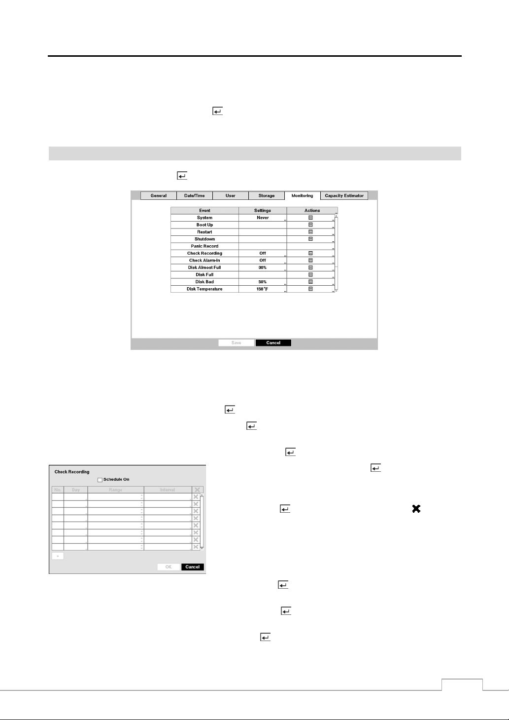
Digital Video Recorder
CAUTION: Do NOT disconnect the USB cable or the power from the device while copying video clips.
If the USB cable is disconnected while copying video clips, archived data might be lost.
Highlight the boxes beside Mirror and press the
button. The DVR can be set up to mirror Source disks to designated
Dest. (destination) disks selected from internal hard disk drives. Refer to th e Chapter 4 – Disk Mirroring for furth er
information on setting up disk mirroring.
Monitoring
Highlight Monitoring and press the
button, and the Monitoring setup screen appears.
Figure 12 : System – Monitoring setup screen.
The DVR can be configured to run self-diagnostics and report the results.
Highlight the Settings box beside the desired event (System, Check Recording, Check Alarm-In, Disk Almost Full,
Disk Bad, or Disk Temperature), and press the
button.
Highlight the Settings box beside System and press the button. You can select the interval that you want the DVR
to run self-diagnostics on the system. You can select from 1 hr. to 30 days or Never.
Highlight the Settings box beside Check Recording and press the button. The Check Recording screen appears.
Highlighting Schedule On and pressing the button toggles On and
Off. When set to On, you can select the day, time range and interval
that you want the DVR to run self-diagnostics on the recorder. The
Interval can be selectable from 1 min. to 7 days or Never. Highlight
the + and press the button to add a schedule item. The
box allows
you to delete a check recording schedule.
Highlight the Settings box beside Check Alarm-In and press the button. You can select the interval that you want
the DVR to run self-diagnostics on Alarm Inputs. You can select from 1 hr. to 30 days or Never.
Highlight the Settings box beside Disk Almost Full, and press the
at which you want the DVR to trigger an alert. Percentage levels range from 80% to 99%.
Highlight the Settings box beside Disk Bad, and press the
which you want the DVR to trigger an alert. Percentage levels range from 10% to 90%.
button. Select the percentage level of disk usage
button. Select percentage level of bad disk sectors at
25
Page 34

Operation Instruction
Highlight the Settings box beside Disk Temperature, and press the
button. Select the temperature of hard disk
drive at which you want the DVR to trigger an alert if the temperature exceeds the defined threshold. Refer to the hard
disk drive manufacturer’s documentation for the correct temperature setting.
The DVR can be set to react to system events. Highlight the Actions box beside the desired event and press the
button. System events can be associated with an Alarm-Out connector, sound the DVR’s internal buzzer, and/or notify
a number of different devices.
NOTE: Alarm-Out action cannot be set to System , Boot Up, Restart and Shutdown events.
For the Notify action t o work, t he DVR should b e register ed in the Speco C entral (Remo te Admin istration
System).
Capacity Estimator
Highlight Capacity Estimator and press the
button, and the Capacity Estimator setup screen appears.
Figure 13 : System – Capacity Estimator setup screen.
The Capacity Estimator screen allows you to calculate the available record time
up the calculation conditions.
of the DVR’s storage device. Set
Video Format: Select the video format: NTSC or PAL. (Local Camera Only)
Number of Cameras: Select the number of cameras.
Number of Audio-In: Select the number of audio inputs.
Average Event Rate: Set the average event rate. (Network Camera Only)
Quality: Set the recorded image quality.
Resolution: Set the recorded image resolution.
Frame Rate: Set the images per second for recording.
Disk Capacity: Set the capacity of the storage device.
Number of Cameras: Select the video format: NTSC or PAL.
Quality: Select the number of cameras.
Average Event Rate: Select the number of audio inputs.
Number of Audio-In: Set the average event rate.
Resolution: Set the recorded image quality.
Frame Rate: Set the recorded image resolution.
Frame Rate: Set the images per second for recording.
Disk Capacity: Set the capacity of the storage device.
Estimated Recordable Time displays the estimated available record time.
NOTE: The estimated available record time can vary from the actual recording time.
26
Page 35

Recording Setup
General
Highlight General and press the
button, and the General setup screen appears.
Digital Video Recorder
Figure 14 : Record – General setup screen.
Highlighting Recycle and pressing the
button toggles between On and Off. In the Recycle mode, the DVR records
over the oldest video data once all available storage space has been used. When Recycle is turned off, the DVR stops
recording once all available storage space has been used.
Highlight the Event Record Dwell box and set the length of time you would like to record for the associated event.
You can set the dwell from 5 seconds to 15 minutes. Refer to Event Actions screen in this chapter for information
regarding event recording.
The DVR can record up to four audio inputs. Highlighting Record Audio and pressing the button toggles between
On and Off.
Highlight the slide bar beside Auto Deletion, and use the Left and Right arrow buttons or Up and Down arrow buttons
to adjust the length of time recorded data will be kept from 1 to 999 days. The DVR automatically deletes video recorded
earlier than the user-defined period under three conditions: at midnight, whenev er the system reboots or whenever the
user changes the Auto Deletion settings. Selecting Never will disable the Auto Deletion function.
Highlight the slide bar beside Limit Time-Lapse Recording, and use the Left and Right arrow buttons to adjust the
length of the maximum storage time for time-lapse recording from 1 to 99 days. The Limit Time-Lapse Recording
feature will function when the storage device has enough space to record video data longer than the preset period. When
this feature is On, the DVR records over the oldes t “tim e-lapse” v ideo once all avai lable storag e has been used in the
Recycle mode, so more event video can be saved. Selecting Never will disable the Limit Time-Lapse Recording function.
NOTE: When the storage device does not have enough space to record video data longer than the preset Limit
Time-Lapse Recording period, the DVR records over the oldest video data (time-lapse or event video)
as it would in the Recycle mode even if this feature is turned On.
The maximum storage time is only an estimate because the amount of space required to store video v aries
depending on many factors such as motion and image complexity.
27
Page 36

Operation Instruction
CAUTION: When more than one disk is installed in the unit, the DVR records video on the d isks
sequentially based on time. And these sequentially recorded videos have the advantage
that you can search recorded video easily even though a disk is removed from the unit.
However, video recorded in the same time range might be saved on different disks b y
channel and by the ty pe of re cor din g mode . Once the Lim it Time-L apse Rec ord ing is s et
to On, the DVR will maintain this recording limitation even after disabling the function.
If you want the DVR to record video on the disks sequentially based on time again, you
must format all disks that are currently used for recording.
Highlighting Use Panic Recording and pressing the
button toggles between On and Off.
Highlight the Panic Recording – Duration box and set the duration of panic recording. Panic recording will stop
automatically after the preset duration as long as
recording. You can set the dwell from 5 minutes to 1 hour. Select No Limit if you want to stop panic recording manually.
(Panic) in the Live Monitoring menu is not selected to stop the panic
Highlighting the Panic Recording – ips and pressing the button allows you to set the images per second for Panic
recording. You can select from 1.00 to 30.00 ips (25.00 ips PAL).
Highlighting the Panic Recording – Quality and pressing the button allows you to set the recorded image quality
for Panic recording. You can select from: Very High, High, Standard and Basic.
Highlighting the Panic Recording – Resolution and pressing the button allows you to set the recorded image
resolution for Panic recording. You can select from: Very High (4CIF/960H), High (2CIF/H960H) and Standard
(CIF/Q960H).
Schedule
Highlight Schedule and press the
button, and the Schedule setup screen appears.
< Simple Mode >
< Advanced Mode >
Figure 15 : Record – Schedule setup screen.
You can program the DVR to record only during certain times based on time, day of the week, and holidays. The smallest
time segment you can use is 15 minutes.
Highlighting Schedule On and pressing the button toggles between On and Off. In the Schedule On mode, the
DVR records video based on the schedule established in the Schedule screen. When turning Schedule recording Off,
you will be asked to confirm your decision, and
will function even when Schedule is turned off.
displays at the top-left corner of each camera screen. Panic recording
displays during panic recording.
Highlight the Schedule Mode box and press the button. You can select between Simple Mode and Advanced
Mode. Selecting Advanced Mode allows you to set up individual recording schedule for each event.
NOTE: Changing the schedule mode will reset all event and action statuses.
Highlight the + and press the
28
button to add a schedule item.
Page 37

Digital Video Recorder
Highlight the box under the Day heading and press the
take place. Choose from: Sun, Mon, Tue, Wed, Thu, Fri, Sat, M~F, Hol and All.
Highlight the box under the Range heading and press the
will take place. The smallest time segment you can use is 15 minutes.
Highlight the box under the Mode heading and press the
Choose from: No Record, Time, Event and Time & Event. (Simple Mode Only)
button to change the days that the scheduled recording will
button to change the time range that the scheduled recording
button to change the recording mode that will be used.
When the DVR is in the No Record mode, it will not record during the preset day and time range as long as (Panic)
in the Live Monitoring menu is not selected. Use the No Record mode when you do NOT want the DVR to record
during certain times.
When the DVR is in the Time
and displays the icon at the top-left corner of the screen during the scheduled times.
, the icon displays at the top-left corner of the screen. The DVR will record
mode
When the DVR is in the Event mode, the red icon displays at the top-left corner of the screen. The DVR will record
and displays the
recoding mode, the yellow
in the Pre-Event mode, the red
icon at the top-left corner of the screen when any event occurs. When the DVR is in the Pre-Event
icon displays when there is no event, and the DVR is not recording. When the DVR is
and display when any event occurs and the DVR starts recoding.
When the DVR is in the Time & Event mode, the DVR will follow the Time settings and the icon displays at the
top-left corner of the screen. The DVR follows the Event settings and the
Highlight the box under the Channels heading and press the
Mode Only)
Highlight the box under the Settings heading and press the
button to sel ect which cameras will b e recor ded. (Simp le
button to define the recording settings.
icon displays.
Figure 16 : Schedule – Settings (Advanced Mode) setup screen.
You can set the ips, Quality and Resolution (ips, Quality, Resolu tion and Dwell for Advanced M ode setup) of th e recording
for any modes you set up in the Mode column. If you do not set the ips, Quality, Resolution and Dwell in the Settings
column, the DVR will follow the default settings. See below for details.
NOTE: The recording speed (ips), quality and resolution used by the network camera are the settings you set
in the camera not those set in the DVR.
Descriptions of the Record icons in the Type column are as follows:
Time-lapse (Time) Alarm-In Motion Video Loss
Video Blind Audio (Network Devices Only) Trip-Zone (Network Devices Only)
Tampering (Network Devices Only) Text-In
Channels that are not defined will use the setting values of the previous schedule item.
29
Page 38

Operation Instruction
NOTE: When multiple events are detected at the same time from a specific channel, the DVR will record event
video with the high setting v alues if the ips , Quality, Re solution and Dwell value s of events are different
from each other. However, the ips will be reset to the supported maximum value when the ips, Quality,
Resolution and Dwell are all set to the highest value. (Advanced Mode Only).
When the ips, quality and reso lution for the network v ideo trans mitter you s et in the D VR are highe r than
those you set in the network video transmitter, the DVR will record video using the settings in the network
video transmitter.
Depending on network cond ition s, the i ps, quality and reso lut ion fo r th e net work v ide o tran smitt er (i ps
for the network camera) may not be attainable.
For network devices using the ONVIF
TM
Conformance Protocol, the DVR records using the profile settings
designated in the DVR preset profile s. You can design ate which pro file to use for record ing when se tting
up the network device. Refer to Camera – Network Camera setup scree n in this chap ter and Append ix –
Remote Setup of Network Devices for further information on setting up the network device.
Highlight the box under the heading and press the
confirm that you want to delete the settings.
Highlight Default… and press the
When recording video from network devices, the archiving speed might decrease.
button to delete the recording settings. You will be asked to
button. The Default screen appears.
Highlighting boxes under ips and pressing the button allows you to set the images per second for Time and Event
recording. You can select from 1.00 to 30.00 ips (25.00 ips PAL).
Highlighting boxes under Quality and pressing the button allows you to set the recorded image quality for Time
and Event recording. You can select from: Very High, High, Standard and Basic.
Highlighting boxes under Resolution and pressing the button allows you to set the recorded image resolution for
Time and Event recording. You can select from: Very High (4CIF/960H), High (2CIF/H960H) and Standard
(CIF/Q960H).
Highlighting boxes under Dwell and pressing the button allows you to set the length of time you would like to record
for the associated event. (Advanced Mode Only)
Pre-Event
Highlight Pre-Event and press the
up in the Record Schedule, a message will display alerting you to this fact.
button, and the Pre-Event setup screen appears. If you do not have Event set
30
Figure 17 : Record – Pre-Event setup screen.
Page 39
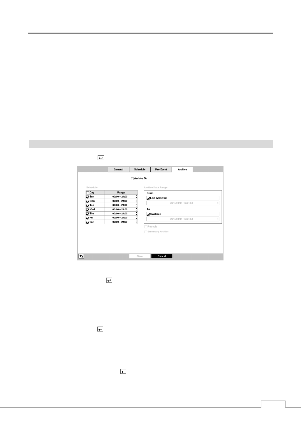
Digital Video Recorder
When the DVR is in the Event Record mode it is possible to have it reco rd images befor e the event occ urs. The Pre -Event
screen allows you to define how to handle pre-event recording.
You can turn individual cameras On or Off for pre-event recording. The image speed can be set from 1.00 to 30.00 ips
(25.00 ips PAL), image quality can be selectable from Very High, High, Standard and Basic, and im age resolution
can be selectable from Very High (4CIF/960H), High (2CIF/H960H) and Standard (CIF/Q960H).
NOTE: Depending on network condition s, the i ps, qu ality and reso lut ion fo r the net work v ideo tran smitt er (i ps
for the network camera) you set may not be attainable.
You can set the amount of time to record prior to the event by adjusting the Dwell. You can set the Dwell from 5 se conds
to 30 minutes. The longer the dwell set, the fewer maximum ips can be set.
NOTE: Depending on the ips, quality and resoluti on of record ed video , the pre- event Dwel l you s et may not be
attainable. (Network Camera Only)
When the DVR is in the Time or Time & Event mode, it ignores the pre-event settings and follows the t ime
settings.
Archive
Highlight Archive and press the
button, and the Archive setup screen appears.
Figure 18 : Record – Archive setup screen.
Highlight Archive On and press the
NOTE: If you have not set up a storage device for archiving, a message appears notifying you of this.
Select the Days and Time Range you want archived.
button to toggle between On and Off.
You can accept the Archive Data Range by leaving the default checkmarks in the Last Archived and Continue boxes.
If you wish to enter specific times and dates in From and To, toggle the checkmarks Off and then enter the time and
date.
Highlight Recycle and press the
button to toggle between On and Off. When Recycle is On and the storage device
is full, the newest archived video data will overwrite the oldest archived data. When Recycle is Off, the DVR will stop
archiving video data until more space is made available.
CAUTION: When the Recycle is On, changing the start date and time for archiving will delete all
archived data after the changed start date and time.
Highlight Summary Archive and press the button to toggle between On and Off. When Summary Archive is On,
the DVR does not archive the entire recorded video, but instead archives 1 or 2 ips from each channel. This allows
the DVR to archive more video and increases archive speed too.
31
Page 40

Operation Instruction
NOTE: The archiving speed might be slower than the recording speed when a large quantity of recorded data
is being archived. In this case, the oldest data can be overwritten by the latest data being recorded.
To prevent data you want to keep from being overwritten, use the Summary Archive function, or set the
recorded image quality to Standard during the archiving process.
Event Setup
Motion
Highlight Motion and press the
button, and the Motion setup screen appears. (Local Cameras Only)
Figure 19 : Event – Motion setup screen.
button
Your DVR has built-in video motion detection. Video motion detection can be turned On or Off for each camera.
Highlighting the box under the Sensitivity heading and pressing the
allows you to adjust the DVR’s sensitiv ity to m otion for Daytime and Nighttim e
independently. There are five settings with 1 being the least sensi tive and 5
being the most sensitive.
You can define the area of the image where you want to detect motion; e.g., a doorway. Highlight the box under the
Zone heading, and press the
button. The Motion Detection Zone screen displays.
The Motion Detection Zone screen is laid over the video for
the selected camera. You can set up motion detection zones
by selecting or clearing blocks.
NOTE: You can set up motion zones one block at a time
Press the button to display the menu screen. The menu on the setup screen has the following functions:
in groups of 8 individual block groups. A block
group is positioned within the image area using
the Up and Down arrow buttons, and individual
blocks within the block groups are selected or
cleared using the camera buttons.
32
Page 41

Digital Video Recorder
Select — Activates highlighted blocks to detect motion.
Clear — Deactivates highlighted blocks so that they will not detect motion.
Reverse — Activates inactive highlighted blocks and deactivates active highlighted blocks.
Select All — Activates all blocks to detect motion.
Clear All — Deactivates all blocks so that they will not detect motion.
Reverse All — Activates inactive blocks and deactivates active blocks.
OK — Accepts changes and closes Zone setup.
Cancel — Exits Zone setup without saving changes.
You can adjust the minimum number of detection blocks that must be
activated to trigger a motion alarm. Highlighting the box under the Min.
Blocks heading and pressing the
button allows you to adjust the minimum
number of detection blocks for Daytime and Nighttime independently.
Smaller numbers provide greater sensitivity because fewer detection blocks
Highlight the box under the Actions and press the
must be activated.
button. The DVR can be set to react to motion detection differently
for each camera. Each camera can be associated with another camera, trigger an Alarm-Out connector, sound the DVR’s
internal buzzer, notify a number of different devices, move PTZ cameras to preset positions, display a camera on a SPOT
monitor, and/or trigger the Digital Deterrent sound.
Turning Zone View On will allow you to observe how the DVR is reacting to motion. When in the motion viewin g
mode, the detection zone of video will be displayed. Any detected motion within the zone will be displayed in red.
You can control excessive event logging and remote notification of motions detected after the motion dwell time by
adjusting the motion ignoring dwell intervals. Highlight the box beside Motion Ignoring Interval and press the
button. A list of intervals ranging from 1 to 5 seconds or Never appears. The DVR will not log and notify motion events
occurred during the preset interval range.
NOTE: The record action for motion events will not be affected by the Motion Ignoring function.
Highlighting Daytime Setup and pressing the button allows you to set up the Daytime range.
Highlight the box beside Daytime and press the button. Use the
Up and Down arrow buttons to set the Daytime range. The DVR will
consider the remaining time range as the Nighttime.
Alarm-In
Highlight Alarm-In and press the
button, and the Alarm-In setup screen appears. (Local Cameras Only)
Figure 20 : Event – Alarm-In setup screen.
33
Page 42

Operation Instruction
The alarm terminal strip on the back of the DVR has inputs associated with each alarm. You can set up each inpu t on
the Alarm-In screen. You can turn each input On or Off by highlighting the alarm number and pressing the
Each input can be given a title. Highlight the desired Title box and press the
allowing you to enter a title name.
Each input can be set as NO (normally open) or NC (normally closed).
Highlight the box under the Actions and press the
button. You can set the actions the DVR will take whenever it
button. A virtual keyboard appears
button.
senses an input on one of its alarm input connectors. Alarm input can be associated with cameras, trigger an Alarm-Out
connector, sound the DVR’s internal buzzer, notify a number of different devices, move PTZ cameras to preset positions,
display a camera on a SPOT monitor, and/or trigger the Digital Deterrent sound.
You can set up the DVR to start panic recording whenever it senses an input on one of its alarm input co nnectors. Highlight
the box beside Panic Record and press the
button. A list of Alarm Inputs appears, and you can select which alarm
input you want associated with panic recording. The DVR will continue panic recording until an input on the selected
alarm input is released as long as
(Panic) in the Live Monitoring menu is not selected to stop th e panic recording.
Video Loss
Highlight Video Loss and press the
button, and the Video Loss setup screen appears. (Local Cameras Only)
Figure 21 : Event – Video Loss setup screen.
Highlight the box under the Actions and press the
button. The DVR can be set to react to video loss differently for
each camera. Each camera can be associated with another cam era, trigger an Alarm-Out connector, sound the DVR’s
internal buzzer, notify a number of different devices, move PTZ cameras to preset positions, and/or displa y a camer a
on a SPOT monitor.
Highlighting the box beside Video Loss Ignoring Interval and pressing the button allows you to set the duration of
a signal loss before the DVR will report a Video Loss. The DVR will not consider any signal loss from a camera to be a
Video Loss if the detected signal loss is shorter than the preset interval.
34
Page 43

Video Blind
Highlight Video Blind and press the
anything is blinding a camera. (Local Cameras Only)
button, and the Video Blind setup screen appe ars. The DVR checks to s ee if
Digital Video Recorder
Figure 22 : Event – Video Blind setup screen.
You can turn individual cameras On or Off for video blind detection by highlighting the camera number and pressing the
button.
Highlighting the box under the Sensitivity heading
allows you to adjust the DVR’s sensitivity to video
blind for Black and White independently from 0 and
1 (least sensitive) to 10 (most sensitive).
NOTE: Video blind might NOT be detected for a camera with a very noisy image especially when set for low
sensitivity values.
Highlighting the box under the Activation Time heading allows you to set the duration before the DVR will report a
Video Blind. The DVR will not consider any blinded camera to be a Video Bl ind if the detected blindness is less than
the Activation Time set on this screen.
Highlight the box under the Actions and press the
button. The DVR can be set to react to video blind differently
for each camera. Each camera can be associated with another camera, trigger an Alarm-Out connector, sound the DVR’s
internal buzzer, notify a number of different devices, move PTZ cameras to preset positions, and/or displa y a camer a
on a SPOT monitor.
Highlight Use Ignoring Time and press the button to toggle between On and Off. When set to On, the DVR will
ignore video blind events occurred during the preset period. Highlighting Time Setup and press the
button allows
you to set up event ignoring time.
Text-In
Highlight Text-In and press the
button, and the Text-In setup screen appears. (Local Cameras Only)
35
Page 44

Operation Instruction
Figure 23 : Event – Text-In setup screen.
The DVR can be set to react to text input from devices such as ATMs (Automated Tell er Machines) and POS (Point
of Sale; i.e., cash registers). This screen allows you to configure the DVR for each text-in device.
Highlight the box under the Setup heading, and press the button. Selecting the Setup heading changes all the
parameters excluding Port settings of all the text input channels.
NOTE: The system performance might be affected when a la rge quantity of text inputs are d etected from sev eral
channels at the same time.
Figure 24 : Text-In Device screen.
Highlight the box beside Port, and press the
(1~16).
NOTE: If you have set the Port as None, you will not be able to make any changes to the screen.
Highlight Setup…, and press the
the RS232, RS485, USB-Serial or LAN ports.
Highlight the box beside Text-In Product, and press the
NOTE: The following description is for a Generic Text Device. The screen changes for different types of text
When using the USB to serial text-in d evice, do NOT r emove the USB cable from the port while th e system
is running.
button. Use the ATM or POS manufacturer’s recommended settings when configuring
input devices, and there will be different parameter boxes for you to enter information.
button. Select from None, RS232, RS485, USB-Serial (1~8) and LAN
button. Select your device from the list.
36
Page 45

Digital Video Recorder
Highlight the box beside Transaction Start, and press the
button. Use the virtual keyboard to enter the Transaction
Start string. Refer to the device manufacturer’s documentation for the text string that the device first sends when a
transaction starts.
If you want the DVR to react to any character sent from the text input device, you will want to turn On Any Character.
Highlight Any Character, and press the
NOTE: If Any Character is turned On, you will not be able to enter any text in the Transaction Start box.
Highlight the box beside Transaction End, and press the
button to toggle between On and Off.
button. Use the virtual keyboard to enter the Transaction
End string. Refer to the device manufacturer’s documentation for the text string that the device sends when a transaction
ends.
Highlight the more line(s) box, and press the
the DVR to record. You can choose from 0 to 10.
Highlight the box beside Line Delimiter, and press the
button. Select the number of additional lines of text that you want
button. Use the virtual keyboard to enter the character(s)
that the device uses to indicate the end of a line . Speci al char acters can be created u sing ^ and a capi tal letter ; e.g., ^ J
for NL (New Line), ^M for CR (Carriage Return). Refer to the device manufacturer’s documentation for Line Delimiter
character(s).
Highlight the box beside Ignore String, and press the
button. Use the virtual keyboard to enter any strings of text
that you want the DVR to ignore. Refer to the device manufacturer’s documentation for text strings that the device
sends during transactions, so you will know which ones you do not want recorded.
Highlight the Case Sensitive box, and press the
button to toggle between On and Off. Refer to the device
manufacturer’s documentation to determine if the text strings are Case Sensitive. If the device distinguishes between
upper and lower case letters, make certain the Case Sensitive box is turned On.
Highlight the box beside Time Out, and press the button. Set the length of time to wait for the new text string. The
DVR will consider a transaction complete if no new text strings are entered between the last text in put and th e dwell
time out. You can adjust the Time Out dwell from 5 seconds to 15 minutes.
Highlight the box under the Actions and press the
button. The DVR can be set to react to text input. Text input
can be associated with cameras, trigger an Alarm-Out connector, sound the DVR’s internal buzzer, notify a number
of different devices, move PTZ cameras to preset positions, and/or display a camera on a SPOT monitor.
Network
Highlight Network and press the
button, and the Network setup screen appears. (Network Devices Only)
Figure 25 : Event – Network setup screen.
Highlighting the box under the Event and pressing the
channel that you selected.
button displays events that occurred on the ne twork device
37
Page 46

Operation Instruction
r
NOTE: Displaying events is supported when the network device is networked with the DVR.
Highlighting the box under the Use and pressing the
Highlighting the box under the Actions and pressing the
button turns each selected event On and Off.
button selects how the DVR reacts to network devices
events. The network devices events can be associated with cameras, trigger an Alarm-Out connector, sound the DVR’s
internal buzzer, notify a number of different devices, move PTZ cameras to preset positions, and/or display associated
local cameras on a SPOT monitor.
NOTE: For the event detection and action to work, the event-related settings for network devices should set
Highlighting the box under the Dwell Time and pressing the
properly.
button allows you to set the dwell time of network
devices events. Dwell times range from 1 second to 15 seconds or Not Using.
Network Setup
General
Highlight General and press the
button, and the General setup screen displays.
Figure 26 : Network – General setup screen.
You can limit the network bandwidth settings so that system does not consume too much network bandwidth. Highlight
the box beside Network Bandwidth Limit and press the Up and Down arrow buttons to set the desired maximum
bandwidth from 50Kbps to 1Gbps.
NOTE: When limiting the network bandwidth, the remote watch im age on the PC running Speco Central o r Speco
Remote might not be displayed properly.
The DVR supports two-way audio communication between a local system and a PC running Speco Central. Highlighting
the box beside Remote Audio Channel and pressing the
to the remote site. Selecting Select From Speco Central will send audio of the channel selected from Speco Central.
NOTE: Depending on network conditions, audio might be interrupted or out of synchronization during
transmission.
button allows you to select the audio channel that sends audio
Highlight Use SSL for Transferring Data and press the button to toggle between On and Off. When it is On, the
security of data except video and audio transmitted for remote monitoring or remote recording can be enhanced by
using the SSL (Secure Sockets Layer) authentication. When using the SSL function, the DVR cannot be connected
with a remote program or a network keyboard which does not support the SSL function.
CAUTION: The
38
emote connection will be disconnected temporarilyafter changing the SSL settings.
Page 47

Digital Video Recorder
NOTE: This product includes software developed by the OpenSSL Project for use in the OpenSSL Toolkit
(http://www.openssl.org/).
Highlight the first box beside Remote Watch – bps/ips. Press the Up and Down arrow buttons to set the Transfer
Speed from 50Kbps to 1Gbps.
Highlight the second box beside Remote Watch – bps/ips. You can select the uni t of measure for the transfer speed
between: bps and ips. Press the
button to set the transfer speed.
Highlight the box beside Remote Watch – Quality and press the button. You can select the Quality from: Very
High, High, Standard and Basic. Press the
button to set the Quality.
Highlight the box beside Remote Watch – Resolution and press the button. You can select the Resolution from:
High (2CIF/H960H) and Standard (CIF/Q960H). Press the
NOTE: The higher Quality and Resolution settings require higher Transfer Speed settings. Th e t r ans fe r sp ee d
you set is the maximum speed. Depending on the net work environment, this sp eed may not be achiev ed.
button to set the Resolution.
Highlight Speco Remote – Use Speco Remote Service and press the button to toggle between On and Off.
See Appendix – Speco Remote for detailed descriptions of the Speco Remote service.
Highlight the box beside Speco Remote – Port and press the button. Set the port number used when accessing
Speco Remote by using the Up and Down arrow buttons to increase or decrease the numbers.
Highlight Use VNC (Virtual Network Computing) and press the button to toggle between On and Off. You will
be able to change the settings if Use VNC is enabled.
NOTE: VNC service allows you to access the DVR and control it remotely using a PC or mobile devices via
Ethernet.
Highlight the box beside Port and press the button. Set the port number of the VNC server obtained from your
system administrator.
Highlight the box beside Password and press the button. A virtual keyboard appears allowing you to enter the
password for VNC connection.
NOTE: Up to three users at a time can access a DVR remotely via VNC service.
When controlling the DVR remotely using a keyboard, shortcut keys perform the following functions as
described below:
Key Function
“←” or “h”
“→” or “l”
“↑ ” or “k”
“↓ ” or “j”
“m” or “” (Windows)
Pressing the “←” or “h” key moves to the left in the menu. It is the same as pressing the Left
arrow button on the front panel.
Pressing the “→” or “i” key moves to the right in the menu. It is the same as pressing the Right
arrow buttons on the front panel.
Pressing the “↑ ” or “k” key moves up in the menu. It is the same as pressing the Up arrow
button on the front panel.
Pressing the “↓ ” or “j" key moves down in the menu. It is the same as pressing the Down
arrow button on the front panel.
Pressing the “m” or “” key displays the Live Monitoring menu or Search menu on the screen.
It is the same as pressing the
MENU button on the front panel.
Pressing the “Enter” or “Return” key selects the highlighted item or completes an entry that
“Enter” or “Return”
you have made during system setup. It is the same as pressing the (Enter) button on the
front panel.
“d” or “PageUp” or
“PageDown”
“c” or “Home”
Pressing the “d” or “PageUp” or “PageDown” key toggles between different display formats.
It is the same as pressing the
MODE button on the front panel.
Pressing the “c” or “Home” key allows you to copy video clips. It is the same as pressing the
COPY button on the front panel.
“F5” Pressing the “F5" key refreshes the current VNC screen.
39
Page 48

Operation Instruction
IP Address
Highlight IP Address and press the
button, and the IP Address setup screen displays.
Figure 27 : Network – IP Address (Manual) setup screen.
Highlight the box beside Type and press the
DHCP and ADSL (with PPPoE). Select the desired type and press the
Selecting Manual from the Type allows you to set up LAN parameters manually.
button. You can select the type of network configuration from: Manual,
button.
Change the numbers by highlighting them and using the Up and Down arrow buttons to increase or decrease the number.
The factory default LAN settings are:
IP Address: 192.168.1.129
Gateway: 192.168.1.254
Subnet Mask: 255.255.255.0
NOTE: You will need to get the appropriate IP Address, Gateway and Subnet Mask from your network
Highlight the box beside DNS Server. Press the Up and Down arrow buttons to set the IP address of the DNS server.
Highlight the Port Number Setup… box and press the button. The Port Number Setup screen appears.
administrator.
NOTE: You will need to get the appropriate Port Numbers for each Speco Central and Speco Remote related
program (Admin, Callback, Watch and Search) from your network administrator.
Change the numbers by highlighting them and using the Up and Down
arrow buttons to increase or decrease the number. The factory default
Port settings are:
Remote Admin: 8200
Remote Callback: 8205
Remote Watch: 8201
Remote Search: 8202
NOTE: The system restarts automatically after changing the port settings.
Do NOT use the same port number for two different programs, otherwise, the DVR cannot be connected
with the PC running Speco Central or Speco Remote.
CAUTION: When changing the port settings, you must change the port settings on the PC running
Speco Central as well. Refer to the Speco Central Operation Instruction for details.
40
Page 49

Digital Video Recorder
Highlight Use UPnP and press the
button to toggle between On and Off. When it is On, port forwarding from the
NAT (Network Address Translation) device to the DVR will be enabled automati cally via UPnP (U niversal Plug and
Play) service. This function will be especially useful when accessing a port on a private IP address.
NOTE: For the UPnP service to work, the NAT device should support the UPnP Port Forwarding function and
the function should be set to enabled.
You cannot change the port settings when Use UPnP is On.
Highlight the Status box and press the button to display the port numbers forwarded from the NAT device via UPnP
service.
Selecting DHCP from the Type and highlighting Save button reads the current IP address of the DVR configured b y
DHCP (Dynamic Host Configuration Protocol) network.
Highlight Auto (Default) and pre ss the button to toggle between On and Off. When it is On, the DVR will obtain
the IP address of the DNS server automatically.
NOTE: Selecting Auto will only be enabled when the DVR is configured for DHCP or an ADSL network.
Selecting ADSL (with PPPoE) allows you to set up the ADSL network.
Highlight the box beside ID and press the button. A virtual keyboard appears allowing you to enter the ID for ADSL
connection.
Highlight the box beside Password and press the button. A virtual keyboard appears allowing you to enter the
password for ADSL connection.
NOTE: Entering the ID and Password and highlighting OK reads the current IP address of the DVR configured
by the ADSL network.
If the DVR is configured for DHCP or an A DSL network, the IP address of the D VR might change whenever
the unit is turned on.
41
Page 50

Operation Instruction
DVRNS
Highlight DVRNS and press the
button, and the DVRNS setup screen displays.
Figure 28 : Network – DVRNS setup screen.
Highlight Use DVRNS and press the
NOTE: DVRNS is the technology that automatically sets up your DVR to work seamlessly for remote viewing
via your network internet connection. For DVRNS to work, naming your DVR will be required.
button to toggle between On and Off.
Highlight the box beside DVRNS Server and press the button. A virtual keyboard appears allowing you to enter
the IP address or domain name of the DVRNS server.
NOTE: You will need to get the IP Address or domain name of the DVRNS Server from your network administrator.
You can use the domain name instead of IP address if you already set up the DNS Server when setting
up the LAN.
Highlight the box beside Port and press the button. Set the port number of the DVRNS server using the Up and
Down arrow buttons to increase or decrease the numbers.
Highlight the box beside DVRNS Name and press the button. A virtual keyboard appears allowing you to enter
the DVR name to be registered on the DVRNS server.
Highlight the Check box and press the button to check whether or not the name you entered can be used.
NOTE: The DVRNS Name you entered should be checked by selecting Check, otherwise the DVRNS changes
will not be saved.
When entering no name or a name already registered on the DVRNS server, an error message displays.
Highlighting Save and pressing the button registers the DVR on the DVRNS server. Proper DVRNS settings will
display the help desk information of the DVRNS server in the box beside Help Desk.
42
Page 51

RTSP
Highlight RTSP and press the
button. The RTSP setup screen displays.
Digital Video Recorder
Figure 29 : Network – RTSP setup screen.
Highlight Enable RTSP (Real-Time Streaming Protocol) and press the
will be able to change the settings if Enable RTSP is enabled.
button to toggle between On and Off. You
Highlight the box beside RTSP Port and press the button. Set the port number of the RTSP server obtained from
your system administrator.
Highlight the box beside RTP Start Port and press the button. Set the start port number of the RTP server obtained
from your system administrator.
Highlight the box beside RTP End Port and press the button. Set the end port number of the RTP server obtained
from your system administrator.
Highlight Use Mobile and press the button to toggle between On and Off. When set to on, you can access a remote
DVR using a Blackberry or other mobile devices.
NOTE: Selecting Use Mobile sets the Speco Remote service to be enabled automatically regardless of Speco
Remote settings.
When using NAT (Network Address Translation) or firewall services, opening all UDP ports allows you
to access a DVR using Blackberry and Android devices.
You can access a remote DVR and monitor live video images using media players, such as VLC Player,
supporting RTSP service. Start the media player on your local PC and enter “rtsp://ID:Password@IP
address:RTSP port number/track ID=‘channel number’”, or start Internet Explorer on your Blackberry
or other mobile devices and enter “http://IP address:Speco Remote port number/”.
Some media players might play video properly depending on network conditions.
RTSP service might not be supported, depending on the type of media player.
43
Page 52

Operation Instruction
Notification
Highlight Notification and press the
button. The Notification setup screen displays .
Figure 30 : Network – Notification setup screen.
You can add and edit notification schedules. Highlight the + and press the
the boxes under the Column heading and pressing the
button allows you to edit the information in those boxes.
button to add a schedule. Highlighting
The Day box allows you to select the days that the notification schedule will be active. The choices are: Sun, Mon,
Tue, Wed, Thu, Fri, Sat, M~F, Hol and All.
The Range box allows you to set the time that the notification schedule will be active in 15-minute increments from
00:00 to 24:00.
Highlight the desired box under the Notify heading, and press the
You can toggle the entire list On and Off by highlighting Notification and pressing the
individual items On and Off by highlighting that item and pressing the
to accept your changes.
NOTE: For the Notify action, the notify item you select should be enabled in the Notification setup s creen and the
button. The Schedule Notify menu appears.
button. You can toggle the
button. Highlight OK and press the
DVR should be registered in the Speco Central (Remote Administrati on System).
button
Highlight the box beside Summary Email Interval and select the interval that you want the DVR to send a summary
email. The DVR will send an email containing a summary of events detected during the preset interval.
Highlight Callback – Setup and press the button, and the Callback screen appears. The DVR can be set up to contact
a computer running Speco Central (Remote Administration System) when an event occurs.
44
Page 53

Digital Video Recorder
Highlight the box under the No. heading and press the button to toggle between On
and Off. You will only be able to change the IP addresses if No. is enabled.
Highlight the IP Address box that you want to change and press the button. Use
the arrow buttons to enter the IP address of the computer you want contacted during an
event. You can enter up to five IP addresses.
Highlight the box beside Retry and enter the number of times you would like the DVR
to try contacting the computer. You can select from 1 to 10 retries.
Highlight Mail – Setup and press the button, and the Mail screen appears. The DVR can be set up to send an email
when an event occurs.
The Mail account can be turned On or Off by
highlighting the boxes under the No. heading and
pressing the button.
Highlight the + and press the button to add a
mail recipient.
Highlight the first box under Recipient and press the button. A virtual
keyboard appears that you can use to enter the recipient’s e-mail address.
Highlight the second box under Recipient and press the button. You
NOTE: The e-mail address must include the “@” character to be a valid address.
Highlight the box under the heading and press the
event detected video segment and attach it to an email when the
NOTE: Attaching a video clip to an email will not be available for the Text-In event.
can select between Manual and listed SMTP mail server providers.
button to toggle between On and Off. The DVR will clip an
box is turned On.
Highlight MP4 Clip and press the button to toggle between On and Off. When it is On, the DVR will attach the
event detected image file with MP4 format to an email.
The Mail accounts can be deleted by highlighting the beside the account and pressing the button.
Highlight SMTP Setup and press the
button. The SMTP Setup screen appears.
Highlight the box beside Type and press the
Manual and listed SMTP mail server providers.
button. You can select between
Highlight the box beside SMTP Server and press the button. A virtual
keyboard appears that you can use to enter the IP address or domain name
of the SMTP server.
NOTE: You will need to get the IP Address or domain name of the SMTP
Server from your network administrator.
NOTE: You can use the domain name instead of IP address if you already
set up the DNS Server when setting up th e Network – IP Address.
Highlight the box beside Port and press the button. Use the arrow buttons to enter the SMTP Server port number
obtained from your system administrator. The default port number is 25.
Highlight Use SSL/TLS and press the button to toggle between On and Off. When it is On, the DVR can send an
email via an SMTP server requiring SSL (Secure Sockets Layer) authentication.
45
Page 54

Operation Instruction
Highlight the box beside Authentication and press the button. An Authentication
screen appears. Highlight Use and press the
Highlight the box beside User/Password and press the
button to toggle between On and Off.
button. A virtual keyboard
appears allowing you to enter the user ID and password.
NOTE: This product includes software developed by the OpenSSL Project for use in the OpenSSL Toolkit
(http://www.openssl.org/).
Highlight the box beside Sender and enter the sender’s e-mail address. Use the virtual keyboard to enter the e-mail
address.
NOTE: The e-mail address must include the “@” character to be a valid address.
Highlight the Test box and press the button to test emailing with the current settings you made.
Highlight SNS – Setup and press the button, and the SNS screen appears. The DVR can be set up to post a message
via SNS (Social Network Service) when an event occurs.
You can add and edit the SNS account on this screen. The SNS
account can be turned On or Off by h ighlighting th e boxes under
the No. heading and pressing the
button.
To add an SNS account, highlight the + and press the button. Highlight the box
beside Type and press the button. Selecting TWITTER from the Type allows
you to post a tweet on Twitter when an event occurs.
Highlight the box beside User Name/Password and press the button. A virtual
The SNS accounts can be deleted by highlighting the beside the account and pressing the button.
NOTE: Posting a tweet might fail because of Twitter limitations.
keyboard appears allowing you to enter the user name and password.
Device Setup
Local Audio
Highlight Local Audio and press the
button, and the Local Audio setup screen appears.
46
Page 55

Digital Video Recorder
Figure 31 : Device – Local Audio setup screen.
The DVR can record up to four audio inputs. Highlight the box beside the input and press the
button. A list of
local cameras appears, and you can select which camera you want associated with that audio input.
Network Audio
Highlight Network Audio and press the
Figure 32 : Device – Network Audio setup screen.
Highlight the box beside the network device input and press the
you can select which audio channel you want associated with that network device input. Audio from the selected
channel will be sent to the network device that is associated with.
button, and the Network Audio setup screen appears.
button. A list of local audio channels appears, and
47
Page 56

Operation Instruction
Digital Deterrent
Highlight Digital Deterrent and press the
to sound when events are detected.
button. The Digital Deterrent setup screen allows you to set up the DVR
Figure 33 : Device – Digital Deterrent setup screen.
Highlight the + and press the
Highlight the box under the Day heading and press the
will take place. Choose from: Sun, Mon, Tue, Wed, Thu, Fri, Sat, M~F, Hol and All.
Highlight the box under the Range heading and press the
deterrent will take place. The smallest time segment you can use is 15 minutes.
Highlight the box under the Associated Event heading and press the
with each digital deterrent.
button to add a digital deterrent schedule item.
button to change the days that the scheduled digital deterrent
button to change the time range that the scheduled digital
button to select which events you want associated
You can select the audio files associate with each event. Highlight the box under
the Associated Audio and press the
and you can select which audio file you want to associated with that event.
button. A list of audio file name appears,
You can import saved audio files or export the current audio files. To import saved audio files, connect the USB device
containing the audio file (.aaf or .wav) to the DVR. Highlight Digital Deterrent – Import… and press the button. Select
the desired audio file and press the Import button to import the selected audio file and change the audio file accordingly.
48
Page 57

NOTE: File format has to be mono G.711 ulaw 16KHz/16bit sampling.
The file names have to be "Sound_1.wav" ~ "Sound_16.wav" or "Sound_1.aaf" ~ "Sound_16.aaf" for
USB import. (USB has to be in FAT32)
The files have to be in the top folder of the USB flash drive.
The file name format is case insensitive.
If the audio file in .wave format, it will be converted to .aaf file in 10 seconds when imported.
Digital Video Recorder
To export the current audio files, connect the USB device to the D VR. Highlight Digital Deterrent – Export… and
press the
enter the file name. Selecting Export will save the current audio file in .aaf file format on the USB device.
button. Highlight the box beside File name and press the button. A virtual keyboard allows you to
Highlight Digital Deterrent – Record… and press the button. You can extract audio files from recorded audio
on the DVR.
Highlight the box beside Channels and press the
to extract audio files from
.
Highlight the box beside From and press the
button. You can select the cameras with recorded audio you want
button to toggle between On and Off. When set to Off, you can enter
a specific Date and Time. When set to On, the search will be from the first recorded audio. When highlighting
pressing the button the bookmark list displays and the bookmark point you selected will be the starting date and time.
Highlight the box beside To and press the
specific Date and Time. When set to On, the search will be to the last recorded audio
the
button the bookmark list displays and the bookmark point you selected will be the ending date and time.
Highlight the box beside File name and press the
by highlighting
and pressing the
button to toggle between On and Off. When set to Off, you can enter a
.
button to select the file name. The selected audio file can be listened
button.
and
When highlighting and pressing
Once you have selected the file name, highlight the Start button and press the button to record the extracted audio
file (up to 10 seconds).
49
Page 58
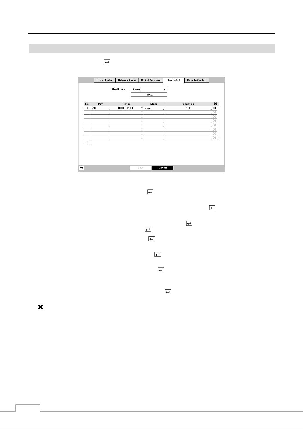
Operation Instruction
Alarm-Out
Highlight Alarm-Out and press the
a schedule for each alarm output from the DVR.
button. The Alarm-Out screen allows you to change the se ttings and establish
Figure 34 : Device – Alarm-Out setup screen.
Highlighting the box beside Dwell Time and pressing the button allows you to set the dwell time of the alarm output.
Dwell times range from 5 seconds to 15 minutes.
Each alarm output can be given its own title by highlighting Title… and pressing the button. A virtual keyboard
appears allowing you to enter the title.
You can add and edit alarm output schedules. Highlight the + and press the button to add a schedule. Highlighting
the boxes under the Column heading and pressing the
button allows you to edit the information in those boxes.
Highlighting the boxes under the Day box and pr essing the button allows you to select the d ays that the alarm sch edule
will be active. The choices are: Sun, Mon, Tue, Wed, Thu, Fri, Sat, M~F, Hol and All.
Highlighting the boxes under the Range box and press ing the button allows you to set the time that the alarm schedu le
will be active in 15-minute increments from 00:00 to 24:00.
Highlighting the boxes under the Mode box and pressing the button allows you to set how the alarm reacts during
the scheduled time. When set to On, the Alarm-Out is active during the scheduled time. When set to Event, the
Alarm-Out is only active when there is an Event during the scheduled time.
Highlighting the boxes under the Channels box and pressing the button allows you to set which alarm outputs will
be active. You can also select the DVR’s internal buzzer.
The box allows you to delete an alarm output schedule. You will be asked to confirm whether or not you really wish
to delete the schedule.
50
Page 59

Remote Control
Highlight Remote Control and press the
make correct settings for a remote keyboard.
Digital Video Recorder
button. The Remote Control setup screen allows you to select a port and
Figure 35 : Device – Remote Control setup screen.
Highlight the box beside Port and select from None, RS232 and RS485. If the RS232 port and RS485 port are in us e
for PTZ control, networking or text input, the remote keyboard cannot be configured.
Highlight Setup… and select the correct Baud Rate, Parity, Data Bits and Stop Bits for the device you are connecting
to the DVR.
Highlight the box beside Remote Control Product and select the device from the list.
Display Setup
OSD
Highlight OSD and press the
the monitor.
button. The OSD screen allows you to selec t what information will be displ ayed on
Figure 36 : Display – OSD setup screen.
51
Page 60

Operation Instruction
Highlighting an item and pressing the button toggles that item On and Off. When an item is On, there is a checkmark
in the box beside it. The following items can be turned On or Off:
Remote Control – The icon
Zoom – The icon
Network – The icon
when audio communication is available between the DVR and a PC running Speco Central via Ethernet. The icon
when VNC service is running.
Freeze & Sequence – The icon
Screen Group – The number of screen group displays when the DVR is not in the 5x4 display mode of the 16-channel DVR,
and 4x3 mode of the 8-channel DVR.
Free Space – The icon
when the DVR is not in the Recycle mode.
Archive – The icon
Mirror – The icon
Date/Time – The current date and time information displays.
User Name – The name of the current user logged in displays.
Background Panel – The background panel at the bottom of the screen displays in black.
Camera No. – The camera number displays at the top-left corner of each camera screen.
Camera Title – The camera title displays at the top-left corner of each camera screen.
Record – The record related icons display on each camera screen.
Audio – The icon
PTZ – The icon
Text-In – The text input strings display on the screen. You can adjust the Display Dwell time (sec.) for the text input strings displayed
on the screen.
Not Connected Reason – The error code displays on the associated camera screen when the network device is not connected
properly. Refer to Appendix – Error Code Notices for error code information.
displays on the enlarged video.
displays when the DVR is archiving recorded data.
displays when the DVR is disk mirroring.
displays on each camera screen for which the DVR can play live audio.
displays on each PTZ camera screen.
displays when the DVR can be controlled by the infrared remote control.
displays when the unit is connected to a network via Ethernet. The icon
displays while in the Freeze mode, and the displays while in the Sequence mode.
displays when the DVR is in the Recycle mode, and the perce ntage of availa ble stora ge space dis plays
displays on each camera
displays
You can adjust the transparency of the setup screens by highlighting Transparency and using the Left and Right arrow
buttons.
Primary Monitor
Highlight Primary Monitor and press the
button, and the Primary Monitor setup screen appears.
Figure 37 : Display – Primary Monitor setup screen.
Highlight the box beside Mode and press the button. You can select between Full Sequence and Cameo Sequence.
Pressing the
SEQ button or selecting (Sequence) in the Live Monitoring menu causes the DVR to sequence cameras,
and the DVR can sequence cameras in two modes: “Full” and “Cameo”. In the Full mode, the DVR sequences through
the cameras and displays them full screen. In the Cameo mode, the bottom right window in a multi-screen f ormat sequences
through the cameras.
52
Page 61
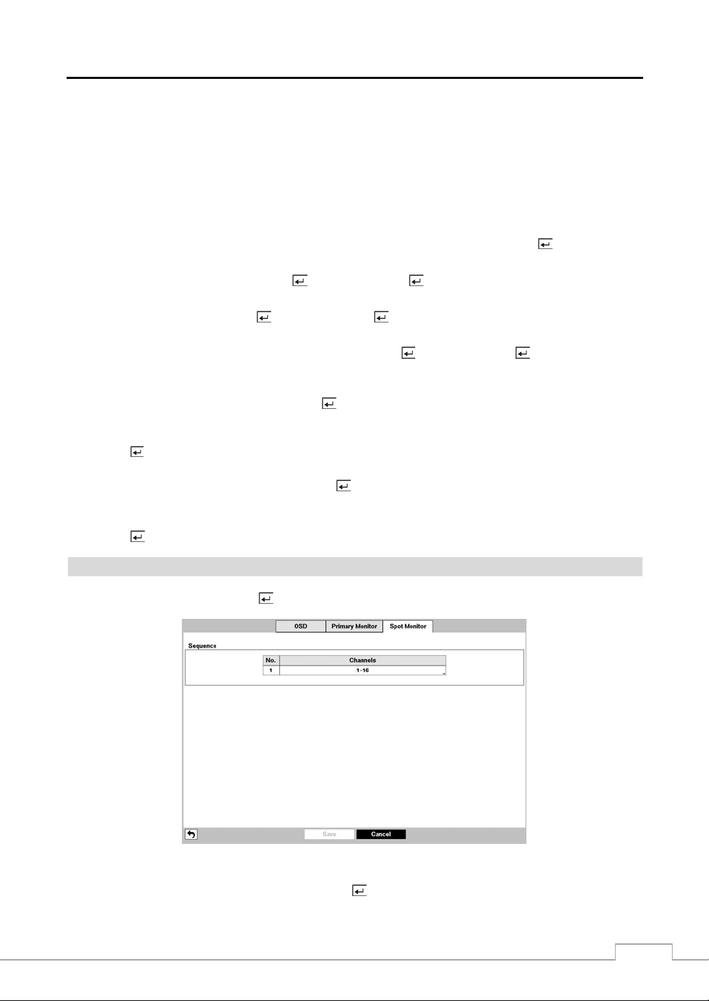
Digital Video Recorder
NOTE: Any cameras that are Off, have lost video or are set to Covert (unless the user has authority to view covert
cameras) will be excluded from the Cameo sequence.
You can define the screen layout in a variety of formats and set the DVR to sequence through the different screen layouts
(pages) so that all the cameras will be displayed. You can also set up the DVR to display one camera or a group of
cameras all the time while cycling through the remaining cameras in a “cameo” window. This can be done with one
camera displayed full screen while displaying the cameo window as a PIP (picture in picture), or displaying the cameras
in a grid pattern with the bottom right window as the cameo.
NOTE: Sequence cannot be used in the 5x4 display mode of the 16-channel and 4x3 mode o f the 8-channel D VR.
You can adjust the display dwell time by highlighting the box beside Interval and pressing the button. You can
select dwell intervals ranging from 3 seconds to 2 minutes.
Highlight Event Monitoring On and press the button. Pressing the button toggles between On and Off. When it
is On, the DVR will display the camera associated with the event when an event occurs.
Highlight Fit To Screen and press the button. Pressing the button toggles between On and Off. When it is On,
the DVR will resize video to fit the primary monitor screen.
Highlight the box beside Set Resolution Automatically and press the button. Pressing the button toggles between
On and Off. When it is On, the resolution will automatically be set to the maximum resolution supported on the monitor
when the DVR reboots.
Highlight the box beside Resolution and press the button. You can select from 1920x1080p, 1920x1080i,
1280x1024 and 1024x768.
NOTE: Changing the resolution-related settings will NOT be applied until you have highlighted Save and pressed
button. A screen will appear confirming that you will need to restart the system to applying the
the
resolution you set.
Highlight the box beside Timing Criteria and press the button. You can select from “Standard”, “HDMI Monitor
Optimized” and “VGA Monitor Optimized.”
Monitor Resolution displays the resolution information of monitors current connected to the DVR . Highlighting Refresh
pressing the
button refreshes the resolution information.
Spot Monitor
Highlight Spot Monitor and press the
button, and the Spot Monitor setup screen appears.
Figure 38 : Display – Spot Monitor setup screen.
Highlight the box in the Channels column and press the
button.
53
Page 62
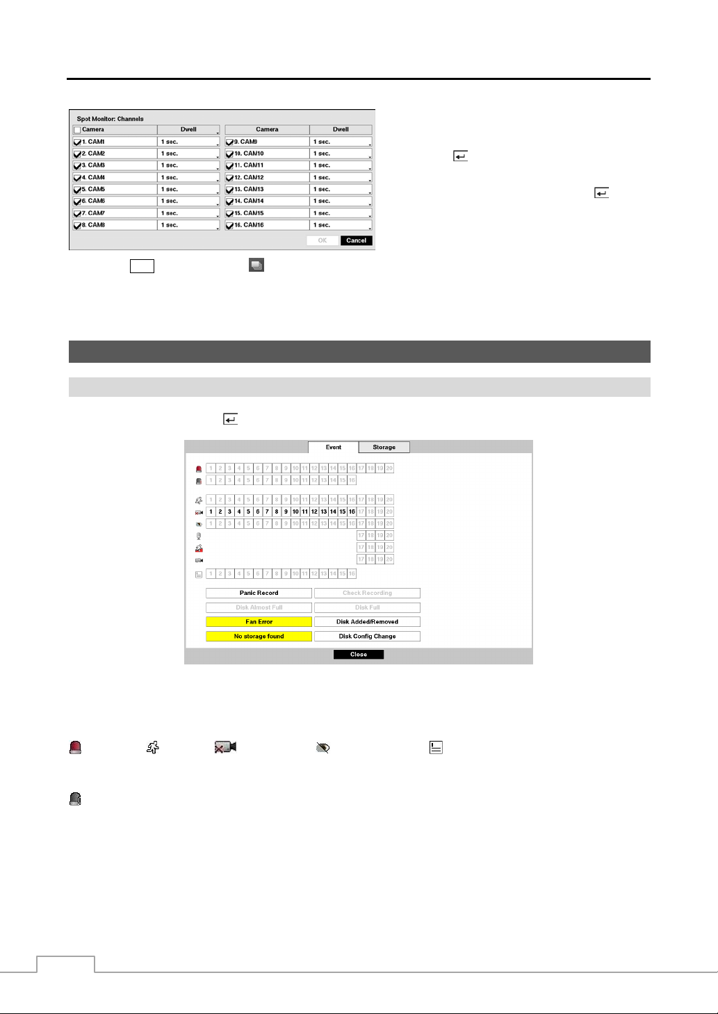
Operation Instruction
You can define which cameras display sequentially
on the Spot Monitor when in the s ingle-scre en dis play
format. Highlighting the box under the Camera and
pressing the
button toggles between On and Off.
You can adjust the display dwell time by highlighting
the box under the Dwell and pressing the
button.
You can select dwell intervals ranging from 1 to 20
seconds.
Pressing the SEQ button or selecting (Sequence) in the Live Monitoring menu causes the DVR to sequence cameras.
NOTE: Sequence cannot be used in the 4x4 display mode of the 16-channel.
Monitoring and playing back video from network devices is not supported on the SPOT monitor.
Status Setup
Event
Highlight Event and press the
button, and the Event setup screen appears.
Figure 39 : Status – Event setup screen.
The Event Status screen displays the status of the DVR’s systems and inputs. Events will be highlighted, and related
channels or events will flicker for five seconds when detected.
(Alarm-In), (Motion), (Video Loss), (Video Blind) and (Text-In) will be highlighted when each
event is detected based on the settings you made in the Alarm-In, Motion, Video Loss, Video Blind and Text-In setup
screen on the Event menu.
(Check Alarm-In) and Check Recording will be highlighted when each event is detected based on the settings
you made in the Monitoring setup screen on the System menu.
Panic Record will be highlighted while the DVR is in the panic recording mode.
Disk Almost Full will be highlighted when the DVR is not in the Recycle mode and the level of disk usage reaches
the Disk Almost Full percentage you made in the System Event setup screen on the Event menu. Disk Full will be
highlighted when the DVR is not in the Recycle mode and all available storage space has been used.
Fan Error will be highlighted when the cooling fan to the left of the power cord on the rear panel is not working for
more than four seconds.
54
Page 63
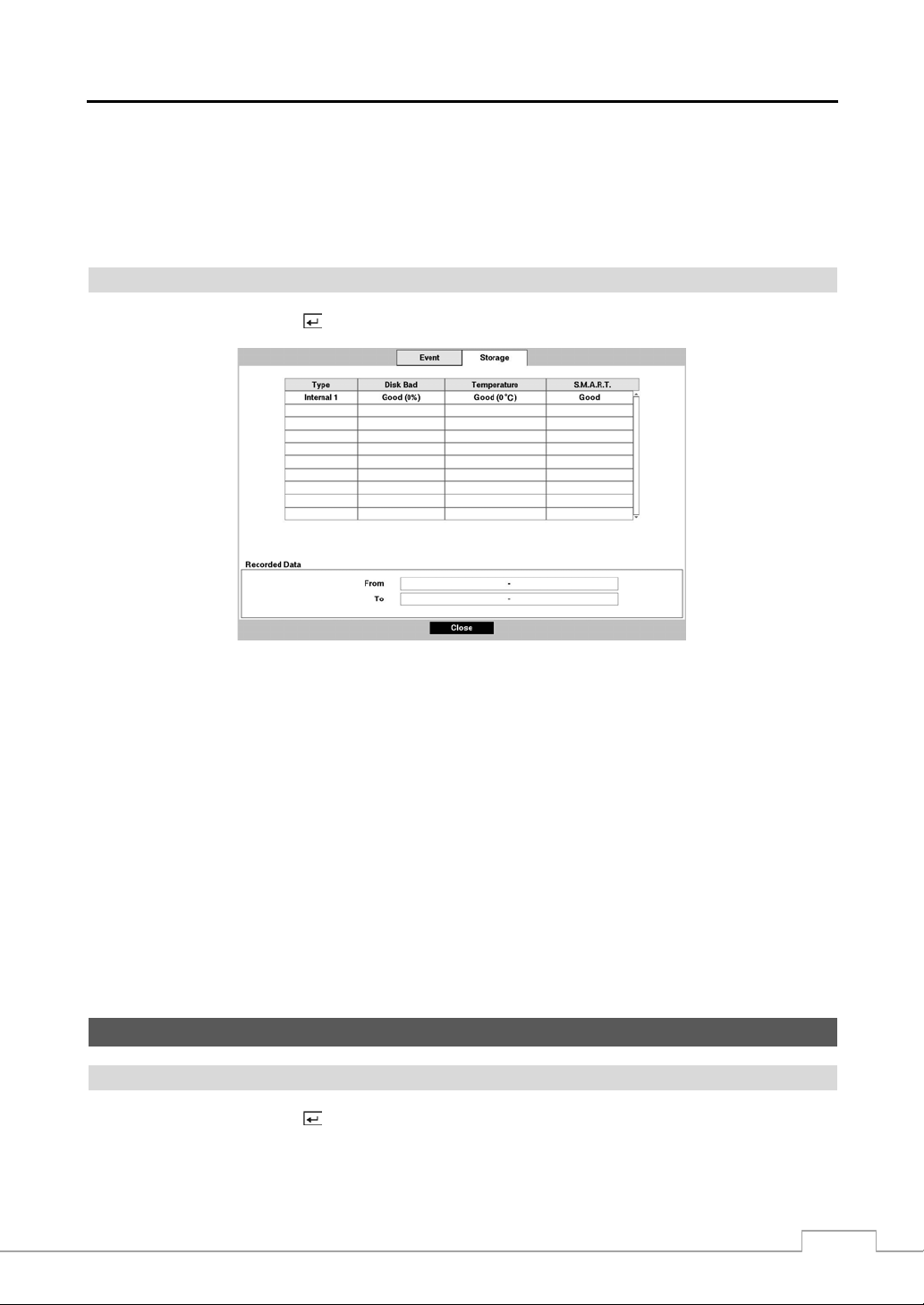
Digital Video Recorder
Disk Added/Removed will be highlighted when the hard disk drive is connected or disconnected while the DVR i s
operating.
No storage found will be highlighted when there is no storage device for recording is installed in th e DVR when the
DVR boots for the first time.
Disk Config Change will be highlighted when the DVR reboots after the hard disk drive has been replaced.
Storage
Highlight Storage and press the
button, and the Storage setup screen appears.
Figure 40 : Status – Storage setup screen.
The Type column displays the type of storage device.
The Disk Bad column displays the percentage of bad sectors. Not formatted indicates the device is not formatted.
The Temperature column displays the temperature of the storage device.
The S.M.A.R.T. column displays “Good”, “Bad” or “N/A”, depending on storage conditions.
Good – The storage condition is normal.
Bad – Data cannot be written on or read from the storage device.
N/A – Storage conditions are normal, however, the S.M.A.R.T. monitoring is not working or supported.
NOTE: When the storage condition is “Bad”, the Event Status – Storage screen displays and you can check
the storage condition for details. Once the “Bad” message displays, replacing the hard disk drive is
recommended, usually within 24 hours.
Temperature and S.M.A.R.T. information will be available only for internal hard disk drives supporting
the SMART (Self-Monitoring Analysis and Reporting Technology) monitoring program.
The box beside Recorded Data – From / To displays the time information of recorded data.
Camera Setup
General
Highlight General and press the
button, and the General setup screen appears. (Local Cameras Only)
55
Page 64

Operation Instruction
Figure 41 : Camera – General setup screen.
You can turn the camera number On or Off, and you can change the T itle of each camera using the virtual keyboard.
You can also determine which cameras will display on the monitors by selecting Normal, Covert 1 or Covert 2 from
a drop-down list in the Use column.
NOTE: When selecting the Covert 1, the DVR displays the camera title and status icons on the covert video. When
selecting the Covert 2, the DVR displays only camera title on the covert video.
A user who does not have Covert Camera View authority ca nnot v iew video from cameras set to Covert
1 or Covert 2 in both the live monitoring and playback modes.
You can select the width resolution supported by the camera between 720 and 960 by highlighting the box und er the
Mode heading and pressing the button.
NOTE: The system restarts automatically after changing the resolution settings.
When selecting the 960 Mode, the total recording speed and playback speed will decrease.
PTZ
Highlight PTZ and press the button, and the PTZ setup screen appears. (Local Cameras Only)
Figure 42 : Camera – PTZ setup screen.
NOTE: You will only be able to set up PTZ devices if the PTZ port is set to RS232 or RS485.
56
Page 65

Digital Video Recorder
Highlight the box in the Product column for the PTZ camera you wish to configure
and press the
from the list and press the
button. A list of PTZ devices appears. Select your camera
button. You will need to connect the camera to
the RS232 or RS485 connector on the back of the DVR following the camera
manufacturer’s instructions.
You can assign IDs to each camera by highlighting the box under the ID heading and pressing the button. Change
the number by highlighting it and using the Up and Down arrow buttons to increase and decrease the number. The
PTZ ID number can be set from 0 to 256.
Highlight the Setup… box and press the button. The Port Setup window appears.
Configure the port’s setting based on the PTZ camera manufacturer’s instructions.
Network Camera
Highlight Network Camera and press the button, and the Network Camera setup screen appears. (Network Devices
Only)
NOTE: “Network Camera” includes both network cameras and network video transmitters.
Figure 43 : Camera – Network Camera setup screen.
Highlight the Scan… box and press the
button, and the Device Scan setup screen appears.
57
Page 66

Operation Instruction
Highlighting the box beside Protocol and pressing the button allows you to select the protocol for the network
device you want to search.
NOTE: Refer to the network device manufacturer’s instructions about enabling the ONVIFTM Conformance protocol
in the device, as procedures may differ for each model.
Highlight the box beside Mode, and press the button. You can select the scan mode between Auto Scan (LAN),
IP Address Scan and Domain Name Scan. Select the desired mode and press the
NOTE: The supported scan modes differ depending on the protocol you selected.
Selecting Auto Scan (LAN) from Mode scans network devices automatically.
If the IP address range of the device is different from that of the DVR, the DVR con s ide rs the I P a dd ress
invalid. In this case, you must change the device’s IP address to register the device.
button.
Selecting IP Address Scan from Mode scans network devices by entering a specific IP address or adjusting the IP
address range. Highlighting Port and pressing the
NOTE: Using the IP Address Scan, you can search for a network device that cannot be searched for using the
Auto Scan (LAN) mode.
button allows you to set the port number used for remote monitoring.
Selecting Domain Name Scan from Mode scans network devices by entering the domain name of the network device.
Highlighting Port and pressing the
NOTE: For the Domain Name Scan feature to work, the DNS sever should be configured during Network – IP
Address setup.
button allows you to set the port number used for remote monitoring.
After selecting the desired scan mode, highlighting Search and pressing the button, the system searches for network
devices and displays them in the list. Selecting Reset allows you to delete the search results list.
NOTE: Depending on the model of network device, the device may not be supported even though the DVR supports
the device's protocol. Ask your dealer or distributor about supported device models.
58
Page 67

Digital Video Recorder
Highlight Device Register and press the
screen appears. Setting up the Authentication is required to register the network device to the DVR.
button to register the selected network device(s) from the list. An Authentication
Highlight the box beside User/Password and press the button. A virtual
keyboard appears allowing you to enter the user ID and password. Highlight
Apply to All Devices and press the
button to apply the same authentication
information to all t he network devices in the li st. When selec ting multip le network
devices in the list, selecting Skip skips the authentication settings for the current
network device and displays the Authentication screen of the next network device.
Proper registration and authentication settings will display registered devices in the list of the Network Camera setup screen.
Highlighting the box under the Settings heading and pressing the
NOTE: The Settings screen will differ depending on the type of protocol that you selected. The following
description is for a network device using the ONVIF
button allows you to change the device settings.
TM
Conformance protocol.
Highlight Enable and press the button to toggle between On and Off. When
it is On, you will be able to change the device settings.
Highlight the box beside Name and press the button. A virtual keyboard
appears allowing you to edit the device name.
You can assign IDs to each camera by highlighting the box beside Camera ID
and pressing the
button. Change the number by highlighting it and using
the Up and Down arrow buttons to increase and decrease the number. (4-ch
Network Video Transmitter Only)
Highlighting the box beside Address and pressing the button allows you
to change the IP address of the device.
Highlight the box beside User/Password and press the button. A virtual
keyboard appears allowing you to enter the user ID and password used when
Highlighting the box beside Stream Protocol and pressing the button allows you to select the protocol for streaming.
Highlighting the box beside Record Protocol and pressing the button allows you to select the protocol for recording.
Highlighting the box beside ONVIF Profile and pressing the button allows you to select a preset ONVIF
changing device settings.
TM
profile.
Highlighting the Port Number Setup… box and pressing the button allows you to select the HTTP server’s port
number and the RTSP server’s port number.
Highlight Authentication and press the button. An Authentication screen appears, and entering Authentication
information is required to change the device settings.
Highlight Use Audio Recording and press the button to toggle between On and Off. When it is On, the DVR will
record audio from the device when video from the network device is recording.
Highlight the Device Remote Setup box and press the button. The Device Remote Setup screen appears. See
Appendix – Remote Setup of Network Devices for details.
59
Page 68

Operation Instruction
NOTE: When the device’s settings have been changed usi ng th e too l prov ided by the dev ice manuf act urer, y ou
might need to register the device to the DVR again for proper operation. Refer to the device manufacturer’s
instructions for proper settings.
60
Page 69

Digital Video Recorder
Chapter 4 — Operation
NOTE: This chapter assumes your DVR has been inst alled and conf igured. If it has not, pl ease refer to Chap ters
The DVR’s controls are similar to a VCR. As with a VCR, the main functions are recording and playing back video.
However, you have much greater control over recording and playing back video. You can establish recording schedules
based on time of day and day of the week. The DVR allows you to search through the recorded video using much
more sophisticated tools than those available with VCRs. Additional DVR features that are not available with VCRs
are remote control and viewing, and recording video at the same time you are watching previously recorded video.
The front panel controls are described in Chapter 3 — Configuration.
Once you have installed the DVR following the instructions in Chapter 2 — Installation, it is ready to record.
As soon as the DVR completes its initialization process, it will begin showing live video on the attached monitor and
playing live audio through the attached speaker. The default mode is to display all cameras at once. Pressing any camera
button will cause that camera to display full screen. It displays live video and plays live audio until the user enters
another mode.
While in the live monitoring mode, pressing the
edge of the screen. Pressing the ESC button hides the menu. You can navigate through menus and items by pressing the
arrow buttons.
2 and 3.
Turning on the Power
Live Monitoring
MENU button displays the following Live Monitoring menu on the right
Figure 44 : Live Monitoring menu.
Login/Logout Monitor Display Freeze
Alarm Digital Deterrent Panic Sequence
Camera Menu Search Setup
NOTE: The Live Monitoring menu also can be displayed by moving the mouse pointer to the right edge of the
screen.
61
Page 70

Operation Instruction
Live Monitoring Menu
Login/Logout
Selecting (Login) in the Live Monitoring menu accesses the Login screen, and you will be asked to select a User
and enter the password to log into the system. Selecting
screen asking you to confirm whether or not you want to log out the current user.
Monitor
Selecting
Selecting Primary displays
(Monitor) in the Live Monitoring menu will allow you to select the monitor from Primary and Spot.
and Spot displays
the selected monitor.
Display
Camera: Selecting
(Display) → Camera and choosing the camera number displays the selected camer a full
screen. It is the same as pressing the individual cam era buttons on the front panel or clicking the lef t mouse button
on a camera image when in one of the multiview formats (i.e., PIP, 2x2, 3x2, 3x3, 4 x3, 4x4 or 5x4). Clicking the
left mouse button on the screen again returns to the previous display mode.
You can change the location of the PIP (Picture-in-Picture) counterclockwise or clockwise by pressing
the Up and Down arrow buttons and change its size by pressing the Left and Right arrow buttons.
To change its location and size by using the mouse, select the PIP and then click the right mouse
button to display the following menu. Select the options you want. You can also change the location
of the PIP by clicking the left mouse button on the PIP window and dragging it to where you want
it located, and change the size of the PIP by clicki ng the left m ouse button at the c orner of th e PIP
window and dragging it until it is the desired size.
Screen Format: Selecting
(Display) → Screen Format and choosing the screen mode displays the cameras in
the selected multiview screen mode (PIP, 2x2, 3x2, 3x3, 4x3, 4x4 or 5x4). Selecting each display mode is the same
as pressing the MODE button or scrolling the mouse wheel up and down when in one of the multiview formats.
Previous Gr oup, Next Grou p: Selecting
or next page.
Edit Group: Selecting (Display) → Edit Group enters to the Active Cameo mode. Refer to the following
Active Cameo Mode section for details.
Camera OSD, Status OSD: Selecting
(Display) → Camera OSD or Status OSD toggles Camera OSD
or Status OSD On and Off.
Freeze
Selecting
(Freeze) in the Live Monitoring menu will freeze the current image on the screen until you select again.
While in the Freeze mode, the icon displays in bottom-left corner if Freeze is selected in the Disp lay setup screen
(OSD tab).
Alarm
Selecting
(Alarm) in the Live Monitoring menu resets the DVR’s outputs including the interna l buzzer dur ing an
alarm. It is the same as pressing the ALARM button.
Digital Deterrent
Selecting
to play manually.
(Digital Deterrent) in the Live Monitoring menu displays the following setup screen and allows the DVR
(Logout) in the Live Monitoring menu displays the Logout
. You can select the screen format and sequence monitoring of
(Display) → Previous Group or Next Group moves to the previous
62
Page 71

Digital Video Recorder
Highlight the box beside Source name and press the
plays the selected file as the di gital deterrent.
button to select the source file to play. Highlighting Trigger
Panic
Selecting (Panic) in the Live Monitoring menu starts panic recording of all cameras, and selecting again stops
panic recording.
Sequence
Selecting
pressing the
(Sequence) in the Live Monitoring menu causes the cameras to display sequentially. It is the same as
SEQ button. When in one of the multi-view form ats, selecting will cause the DVR to go through predefined
screen layouts (Full Sequence). Or, the bottom, right screen will display live cameras sequentially (Cameo Sequence).
For example, if you select
< Full Sequence >
in the 2x2 format, the DVR changes pages as follows:
< Cameo Sequence >
Selecting again in the Live Monitoring menu exits the Sequence mode. While in the Sequence mode, the icon
displays in bottom-left corner if Sequence is selected in the Display setup screen (OSD tab). If all the cameras in a
page are Off, or have lost video or are set to Covert (unless the user has authority to view covert cameras), that page
will be excluded from the sequence.
NOTE: The Full Sequence for the full sequence monitoring and the Cameo Sequence for the cameo sequence
monitoring should be selected in the Display setup screen (Primary Monitor tab).
Camera Menu
PTZ: Selecting
camera as long as it has Pan, Tilt and Zoom capabilities. It is the same as pressing the
(Camera Menu) → PTZ and choosing the camera number allows you to control the selected
PTZ button. Refer to the
following PTZ Mode section for details.
Zoom: Selecting
(Camera Menu) → Zoom and choosing the camera number zooms the current image of the
selected camera on the screen. Refer to the following Zoom Mode section for details.
Audio: Selecting (Camera Menu) → Audio toggles audio output On and Off.
Mic: Selecting (Camera Menu) → Mic toggles the DVR’s audio that is sent to the network device On and Off.
Color Control: Selecting
(Camera Menu) → Color Control and choosing the camera number allows you to
control brightness, contrast, hue and saturation for each camera for the selected camera if a user who has Color Control
authority logs into the system. It is the same as pressing and holding a camera button for a few seconds.
Information: Selecting (Camera Menu) → Information and choosing the network camera number allows you
to check the information of the selected network camera.
NOTE: It is important that cameras and monitors are correctly installed and adjusted prior to making any image
adjustments using the DVR’s controls.
Any image adjustments you make will be applied to both the live video on the monitors and the recorded
video.
The Camera Menu also can be displayed by clicking the right mouse button on the screen while in the
live monitoring mode.
Search
Selecting
(Search) in the Live Monitoring menu exits the live monitoring mode and enters the search mode. It is
the same as pressing the PLAY/STOP button.
63
Page 72

Operation Instruction
Setup
Selecting (Setup) in the Live Monitoring menu enters the Main Setup screen. Refer to Chapter 3 ─ Configuration
for detailed descriptions of system setup.
Active Cameo Mode
You can enter the Active Cameo mode by selecting Edit Group from the Live Monitoring – Display menu or pressing
button on the front panel in any multi-view format. The yellow outline surrounding the video indicates the active
the
cameo, and pressing the arrow buttons moves the active cameo. Pr essing the
Selecting Exit Group Edit in the cameo menu displayed when pressing the
mode. The active cameo mode will remains in effect for 15 seconds if there is no further operation.
button exits the Active Cameo mode.
MENU button also exits the Active Cameo
In active cameo mode, press the button for the camera you want to display in the active cameo. After setting the camera
number to active cameo, the DVR moves the active cameo to the next cameo. Wh en the camera numb er exists on the
current screen, the active cameo is changed with the existing camera number. When the camera number does not exist
on the current screen, the active cameo is replaced by the camera number. You can change the screen layout in this way.
Zoom Mode
You can enlarge an area of the video by selecting Zoom from the Live Monitoring – Camera menu. For a few seconds
after selecting Zoom, a rectangle displays on the screen. A rectangle s hows the area that will be enlarged. You can
move the rectangle around using the arrow buttons. Pressing the button or turning the Jog Dial counterclockwise
in the Zoom mode toggles the zoom size between 2x, 3x and 4x. Exit the Zoom mode by selecting (Exit) in the Zoom
menu displayed when pressing the
MENU button. While in the Zoom mode, the icon displays if Zoom is selected
in the Display setup screen (OSD tab).
PTZ Mode
If a user who has PTZ Control authority logs into the system, the user can control PTZ cameras. The DVR will control
cameras with Pan, Tilt and Zoom capabilities. Press the PTZ button to display the PTZ camera menu and enter the PTZ
mode, and press the button again to exit the PTZ mode.
Select the PTZ camera you wish to control by selecting it from the menu. The icon
To use the front panel buttons, press the Left and Right arrow buttons to pan left and right. Press the
Up and Down arrow buttons to tilt the camera up and down. Press the camera button 1 to zoom in,
and press the button 4 to zoom out. You can use the button 2 and button 5 to focus the image.
You can establish preset positions for PTZ cameras. Press the button 6 to establish Presets.
You can quickly move PTZ cameras to Preset positions. Press the button 3 to view an established
camera Preset position.
displays on the PTZ camera screen.
Figure 45 : PTZ Select Camera menu.
64
Page 73

< Set Preset > < Move to Preset >
Figure 46 : PTZ Preset menu.
While in the PTZ mode, pressing the
displaying at the top of the screen displays the Advanced PTZ menu.
Set the feature you wish to control by selecting it from the menu. Refer to the camera m anufacturer’s
instructions for the proper settings. Depending on the camera specifications, some features may
not be supported.
Digital Video Recorder
You can save camera position settings as “presets” so that you can go directly
to desired views.
Once you have the camera at the desired settings, press the camera button 6,
and the Set Preset dialog box will appear. Select the number you want to
assign to the preset and press the
the preset name.
button. Use the virtual keyboard to enter
Press the camera but ton 3to load the PTZ pr eset and the Move to Preset dialog
box will appear. Select the desired preset and press the
button to load the
preset.
MENU button and selecting (Advanced PTZ) in the menu
You can use a mouse for convenient PTZ control. Click the left mouse button on the image and move that image in
the direction you want to by dragging the mouse. Use the mouse wheel to zoom in and out. Position the mouse pointer
at the bottom of the screen, and the following PTZ toolbar will display.
Clicking on the left side exits the toolbar. If you want to display the toolbar again, position
the mouse pointer at the bottom of the screen. Change the toolbar location by clicking the
empty space on the left side of the toolbar and drag it to where you want it located on the
screen. Use the arrow buttons on the toolbar to pan or t ilt th e c ame ra in th e dir ectio n you
want. The other controls on the toolbar perform as described below:
Zoom In / Out
Iris Open / Close
Advanced PTZ
Focus Near / Far
Set / Load Preset
Event Monitoring
When an event occurs, the DVR will dis play the camera associated with the event and the icon displays on screen
if Event Monitoring is selected in the Display setup screen (Primary Monitor tab).
How the cameras are displayed depends on the number of cameras associated with the event. If one camera is associated
with the event, the DVR will display the camera full scre en. If two to four cameras ar e as sociated with the event , the
DVR will display the cameras on a 2x2 screen. If five to nine cameras are associated with the event, the DVR will
display the cameras on a 3x2 or 3x3 screen. If 10 or more cameras are associated with the event, the DVR will display
the cameras on a 4x3 or 4x4 screen.
Event monitoring lasts for the dwell time set for event recording. After the dwell time has elapsed, the monitor returns
to the previous screen unless another event has occurred. If you want to r eturn to the live m onitoring mode before th e
dwell time has elapsed, press the
MODE button or one of the camera buttons.
65
Page 74

Operation Instruction
Covert Camera
If a camera is set up as Covert 1 in the Camera setup screen (General tab), that camera will no t be displayed unless a
user with Covert Camera View authority logs into the system. However the camera title and status icons will be
displayed on the monitor.
If a camera is set up as Covert 2 in the Camera setup screen (Gener al tab), that camera appears to b e Off unless a us er
with Covert Camera View authority logs into the system. The camera title will be grayed out and status icons will
not be displayed on the monitor.
NOTE: When a camera is set up as Covert 1, the DVR displays the camera title and status icons on the covert
video. When set up as Covert 2, the DVR displays only the camera title on the covert video.
If a user who has Covert Camera View authority logs into the system, the user can view video from cam eras set to
Covert 1 or Covert 2 including the camera titles and status icons.
NOTE: The covert camera function of network devices follows the settings you set in the network device not
in the DVR.
Spot Monitoring
NOTE: Spot monitoring video from network devices will not be supported.
The multiview screen display (2x2, 3x3 or 4x4) and sequ ence monitoring is supported on a Spot Monitor. Selecting
Spot after selecting
Select
3x3 and 4x4 you want to display on a Spot Monitor.
(Display) → Screen Format in the Live Monitoring menu and then select the screen mode between 2x2,
(Monitor) in the Live Monitoring menu allows you to control a Spot Monitor.
Selecting (Sequence) in the Live Monitoring menu causes the cameras to display sequentially, and selecting again
stops sequencing on a Spot Monitor. Any cameras that are Off, have lost video or are set to Covert (unless the user
has authority to view covert cameras) will be excluded from the sequence. When the Spot Monitor is in the sequenc e
mode, you can set the camera’s display dwell time. Refer to Chapter 3 – Configuration – Display Setup section for details.
NOTE: Sequence cannot be used in the 4x4 display mode of the 16-channel.
Recording Video
Once you have installed the DVR following the instructions in Chapter 2 — Installation, it is ready to record. The DVR
will start recording based on the settings you made in the Record setup screen. See Chapter3 — Configuration.
Recycle On or Recycle Off. The factory default is Recy cle On. It does this by recording over the oldest video once
the hard disk is full. Setting the DVR to Recycle Off causes it to stop recording once the hard disk is full.
NOTE: When recording video from network devices, the DVR has a recording speed of 120 ips with Standard
Although you will be able to record without changing the unit from its original factor y settings, you will want to take
advantages of the DVR’s many tools. See Chapter 3 — Configuration for detailed descriptions of the recording mode
options.
image quality and a resolution setting of 1920x1 080 fo r each channel. Depend ing on the DVR’s operating
situation and network environment, the recording speed of network devices might increase or decrease.
This recoding speed standard is based on 1-Gbps Ethernet when the DVR is only recording video from
network devices, and the monitoring feature is not being used.
The recording speed (ips) and resolution for the network camera will follow the settings you set in the
camera and not the settings in the DVR.
When the recording speed and resolution for th e net work v ideo tran smitter y ou set in the DVR a re hi gher
than the ones you set in the network video transmitter, the DVR will record video at the recording speed
and resolution you set in the network video transmitter.
66
Page 75

Digital Video Recorder
Panic Recording
Selecting
(Panic) in the Live Monitoring menu or Search menu starts panic recording of all cameras. Selecting
again stops panic recording. If you set the Panic Recording Duration in the Panic Record setup screen, panic recording
will stop automatically according to the preset duration as long as
NOTE: When the DVR is not in the Recycle mode and all av ailable sto rage space h as been used, panic reco rding
will not operate.
is not selected.
Recording Audio
If the DVR was set up to record audio, it will record audio from up to four inputs when video is recording.
NOTE: Make certain you comply with all local and federal laws and regulations when recording audio.
Playing Recorded Video
If a user who has Search authority logs into the system, the user can view recorded image. Once video has been recorded,
you can view it by pressing the (Play/Pause) button on the Record Table Search screen.
The DVR supports the Triplex function: monitoring, recording and playing back at the same time. Pressing the
button when in one of the multi-view formats enters the Triplex mode and displays the Select Playback Camera menu.
Selecting All Channels plays back video of all cameras. The DVR maintains the same display format
as it does in the live mode except for the PIP format. You can also change the screen layout in the
same way as you do in the live mode.
Selecting the camera number under Triplex enters the Triplex mode and plays back video of the selected
camera. When in the single-screen display format, the camera currently dis p layed on the screen will
be selected and when in the PIP display format, the camera displayed on the PIP screen will be selected
for the search channel. During the Triplex mode, the DVR maintains the same display format as it does
in the live mode. A red outline surrounding the video and the camera title indicates the search channel.
While in the Triplex Mode, the DVR continues r ecording cameras as they were set up in the recordi ng
schedule. Also, live monitoring will continue except for the camera that has been selected for playback.
NOTE: While in the triplex mode, the playback speed might decrease when monitoring live video
of network devices.
PLAY/STOP
Figure 47 : Select Playback Camera menu.
When playing video for the first time, the DVR will display the m o st re cent image. When playing video subsequent
times, the DVR will start playing video from the last recalled image. Recorded audio will be played when the DVR
displays a camera with recorded audio in full screen mode.
NOTE: Only the administrator and users with Covert Camera Vi ew authority can v iew video from covert cam eras.
The covert cameras in the playback mode are determined by the current camera settings.
Camera Buttons (1 to 16): Pressing the individual camera buttons will cause the selected camera to display full screen.
Arrow Buttons: In the playback mode, pressing the Left arrow button plays video backward at high speed. Pressing the
button again toggles the playback speed from
, and . The screen displays , and respectively.
Pressing the Right arrow button plays video forward at high speed. Pressing the button again toggles the playback speed
from , and . The screen displays , and
respectively.
67
Page 76

Operation Instruction
Jog Dial, Shuttle Ring
Jog Dial: The Jog Dial only functions when playback video has been paused . B y turning the jog di al clockwise,
you can play video forward image-by-image. By turning the jog dial counterclockwise, you p lay video backwar d
image-by-image.
Shuttle Ring: The Shuttle Ring only functions in the Playback mode. The Shuttle Ring is spring loaded and returns
to the center position when released . Turning th e ring clo ckwise plays video forward. Turning the ring counterclockwise
plays video backward. Playback speed varies with the amount the ring is turned. The playback speeds are
, x0.5, , , and
. When you release the ring, it snaps back to the center position and the v ideo pauses.
, ,
Mode Button: Pressing the MODE button toggles different display formats. The available formats are: PIP, 2x2, 3x2,
3x3, 4x3, 4x4 and 5x4.
You can use a mouse for convenient playback control. Position the mouse pointer on the playback screen, and the
following Record Table Search (Compact View Mode) screen will display. The individual controls on the toolbar
perform the following functions as described below:
Go to the previous image Play/Pause Go to the next image
Fast backward play Fast forward play
Searching Video
While in the search mode, pressing the MENU button displays the following Search menu to the right edge of the screen.
Pressing the ESC button hides the menu. You can navigate through menus and items by pressing the arrow buttons.
Figure 48 : Search menu.
Search Go To Display Alarm
Panic Camera menu Export Data Source Exit
Digital Deterrent
NOTE: The Search menu also can be displayed by moving the mouse pointer to the right edge of the screen.
68
Page 77

Digital Video Recorder
Search Menu
Search
Event Log Se arc h: Selecting
Event Log Search section for details.
Record Table Search: Selecting (Search) → Record Table Search selects using a recording table. See
the following Record Table Search section for details.
Motion Search: Selecting
section for details.
Text-In Search: Selecting
Search section for details.
EZ Search: Selecting (Search) → EZ Search selects video in 4x4 display format using da y, hour or minute
precision. See the following EZ Search section for details.
Go To
Go to the First: Selecting
Go to the Last: Selecting
Go to the Date/Time: Selecting
Once you have set the date and time you want, press the button. Then highlight Go and press the button. The
selected date and time will display. (If no video was recorded during the selected time, a message appears alerting you
that no image was recorded at that time.) The playback controls on the Record Table Search screen, and Jog and Shuttle
on the front panel can now be used to review the surrounding video.
Bookmark: Selecting
following Bookmarks section for details.
Display
Camera: Selecting
(Display) → Camera and choosing the camera number displays the selected camer a full
screen. It is the same as pressing the individual cam era buttons on the front panel or clicking the lef t mouse button
on a camera image when in one of the multiview formats (i.e., PIP, 2x2, 3x2, 3x3, 4 x3, 4x4 or 5x4). Clicking the
left mouse button on the screen again returns to the previous display mode.
Screen Format: Selecting (Display) → Screen Format and choosing the screen mode displays the cameras
in the selected multiview screen mode (PIP, 2x2, 3x2, 3x3, 4x3, 4x4 or 5x4). Selecting each display mode is the
same as pressing the
MODE button or scrolling the mouse wheel up and down when in one of the multiview formats.
Previous Gr oup, Next Grou p: Selecting
or next page.
Edit Group: Selecting
Monitoring – Active Cameo Mode section for details.
Camera OS D , Stat us OS D: Selecting (Display) → Camera OSD or Status OSD toggles Camera OSD or
Status OSD On and Off.
Alarm
Selecting (Alarm) in the Search menu resets the DVR’s outputs including the internal buzzer during an alarm. It
is the same as pressing the ALARM button.
(Search) → Event Log Search sel ects video from the event lo g. See the fo llowing
(Search) → Motion Search selects motion events. See the following Motion Search
(Search) → Text-In Search selects text input strings. See the following Text-In
(Go To) → Go to the First displays the first recorded image.
(Go To) → Go to the Last displays the last recorded image.
(Go To) → Go to the Date/Time displays the Go to the Date/Time screen.
Move the cursor over the date and time and press the button. You can use
the Left and Right arrow buttons to highlight the year, month, day, hours, minutes
and seconds. Use the Up and Down arrow buttons to change to the date and time
you want to search for video.
(Go To) → Bookmark adds the current playback point to the bookmark list. See the
(Display) → Previous Group or Next Group moves to the previous
(Display) → Edit Group enters to the Active Cameo mode. Refer to the previous Live
69
Page 78

Operation Instruction
Digital Deterrent
Selecting (Digital Deterrent) in the Search menu displays the following setup screen and allows the DVR to play
manually.
Highlight the box beside Source name and press the
plays the selected file as the di gital deterrent.
button to select the source file to play. Highlighting Trigger
Panic
Selecting
(Panic) in the Search me nu star ts panic recording of all cameras, and sel ecting again stops panic recording.
Camera Menu
Zoom: Selecting
(Camera Menu) → Zoom and choosing the camera number zooms the current playback image
of the selected camera on the screen.
Audi o: Selecting (Camera Menu) → Audio toggles audio playback On and Off. Recorded audio will be played
when the DVR displays a camera with recorded audio in full screen mode.
Show/Hide Text-In: Selecting
data on the screen if the video was recorded with text-in data.
NOTE: The Camera Menu also can be displayed by clicking the right mouse button on the screen while in the
search mode.
(Camera Menu) → Show Text-In or Hide Text-In shows or hides the text-in
Export
EZ Copy: Selecting
(Export) → EZ Copy will set the start ing point of the v ideo to be clip copie d, and the
icon displays at the bottom-left corner of the screen. Selecting EZ Copy again will set the ending point of the video
to be clip copied and displays the Clip-Copy screen. See the following Clip Copy section for details.
Clip-Copy: Select
(Export) → Clip-Copy, and the Clip-Copy screen appears to allow clip copy setup. See
the following Clip Copy section for details.
Digital Deterrent Recording: Selecting
(Export) → Digi tal Deterrent Re cording allows you to extract audio
files from recorded audio on the DVR. Refer to Chapter 3 – Configuration – Digital Deterrent section fo r details
Print: Selecting (Export) → Print allows you to print a selected image. See the following Print section for deta ils.
Data Source
Selecting (Data Source) in the Search menu allows you to select th e data source to b e searched. Sele cting Record
searches recorded data on primary storage installed in the DVR, and selecting Archive searches archived data o n second ary
storage installed in the DVR.
Exit
Selecting
(Exit) in the Search menu exits the search mode and enters the live monitoring mode.
70
Page 79

Event Log Search
Digital Video Recorder
Figure 49 : Event Log Search screen.
The DVR maintains a log of each time the Alarm Input port is activated. The Event Log Search screen displays this
list. Use the arrow buttons to highlight the event for which you would like to see video.
The Event Log Search screen can also be accessed by pressing the ALARM button unless there is an alarm. There is
no determined user authority to display the Event Log Search screen, however, the event video will not be played unless
a user with Search authority logs into the system
.
Pressing the button will extract the event video and display the first image of the event. Pressing the (Play/P a u se)
button on the Record Table Search screen will start playing the “event” video segment. Pressing the PLAY/STOP button
returns to live monitoring.
NOTE:
You can also narrow your event search by selecting the Option… button and setting up the new search condition.
It is possible that no recorded image displays on the current screen. Press the
the screen mode to 5x4. You will be able to easily see the camera have recorded video during target time.
MODE button and change
You can search video from the first to last recorded images, or you can set the start and stop times and dates.
Highlight the box beside From and press the button to toggle between On and Off. When set to Off, you can enter
a specific Date and Time. When set to On, the search will be from the first recorded image.
Highlight the box beside To and press the button to toggle between On and Off. When set to Off, you can en ter a
specific Date and Time. When set to On, the search will be to the last recorded image
.
71
Page 80

Operation Instruction
Highlight the box beside Check Time Overlap and press the
button. It toggles between On and Off. You will only
be able to turn the Check Time Overlap on or off if a user-defined date and time is set to From and To. If the DVR’s
date and time have been reset, it is possible for the DVR to h ave more than one overlapping star t and stop time. When
set to On, you will be asked to select one of the overlapping start and stop time. When set to Off, the DVR will display
search results from all start times to all stop times.
Highlight the box beside Alarm-In and press the button. You can select the alarm inputs that you want to include
in your search.
Highlight the box beside Motion and press the button. You can select the cameras for which you want any reports
of motion detection.
Highlight the box beside Video Loss and press the button. You can select the cameras for which you want any
reports of lost video.
Highlight the box beside Video Blind and press the button. You can select the cameras for which you want any
reports of blind video.
Highlight the box beside Audio Detection and press the button. You can select the cameras for which you want
any reports of audio input. (Network Devices Only)
Highlight the box beside Trip-Zone and press the button. You can select the cameras for which you want any reports
of trip-zone. (Network Devices Only)
Highlight the box beside Tampering and press the button. You can select the cameras for which you want any
reports of tampering. (Network Devices Only)
Highlight the box beside Text-In and press the button. You can select the text-in devices which you want any reports
of text input.
Highlight the box beside Record Channels and press the button. You can select the cameras that you want to search
for any reports of event recorded data. The DVR will display the e vents (not the cam era channels) that oc curred and
that also are recorded on the camera channel that you selected. If you do not select a camera ch annel in this field, the
DVR will search events that are not associated with cameras.
You can also toggle On and Off self-diagnostic System Events as part of your search. The choices are:
Panic Record
Check Recording
Check Alarm-In
Disk Almost Full
Disk Bad
Disk Temperature
Disk S.M.A.R.T.
Fan Error
Disk Added/Removed
Disk Config Change
Once you set your desired search conditions, highlight Search and press the button to display the search results in
the Event Log Search screen. Selecting Cancel exits the screen without saving the changes.
72
Page 81

Record Table Search
< Compact View >
Digital Video Recorder
< Standard View >
< Expanded View >
Figure 50 : Record Table Search screen.
Recording information about video images currently displayed on the screen displays on the recording status bar. A
grey vertical line indicates the current search position. To search specific video, move the vertical line by using the
Left or Right arrow buttons on the front panel or by clicking the mouse on the desired segment.
If the DVR’s time and date have been reset to a time that is earlier than some recorded video, it is possible for the DVR
to have more than one video stream in the same time range. In this case, the overlapping time range in the record table
will be separated by a yellow vertical line
NOTE: The recorded data in the time range located after the white vertical line is the latest.
.
There are three view modes. Standard view, Expanded view and Compact view. Standard view (default) displays
combined recording information of all camera channels currently displayed on the screen. In the Standard view mode,
selecting the
recording information of each camera channel currently displayed on the screen. Selecting the
view mode switches to the Compact view mode which displays only the toolbar. Selecting the
view mode switches to the Standard view mode, and selecting the
Standard view mode.
Selecting
and selecting
icon located at the bottom switches to the Expanded view mode. The Expanded view displays the
icon in the Standard
icon in the Compact
icon in the Expanded view mode switches to the
located at the bottom zooms the record table. Selecting
or
displays 24 hours (3-minute based) at once. To move to earlier or later times that are not shown in
displays eight hours (1-minute based),
the current record table screen, select th e arrows located at the end of the tim es by using the arrow bu ttons on the front
panel.
73
Page 82

Operation Instruction
NOTE: If the DVR has images recorded in more than one recording mode in the same time range, the recording
Selecting
status bar displays recording information in the following priority order: Panic → Pre-Event → Event →
Time → Irregular (Irregular recording caused by temporary disconnection from the network dev ice). The
color of the bar indicates different recording modes: Red for Panic, Yellow for Pre-Ev ent, Purple for Event,
and Blue for Time.
located at the bottom displays the Calendar Search screen.
Days with recorded video display on the calendar with white numbers. You can highlight
the days with recorded video by using the arrow buttons. Once you have highlighted
a day, press the
button to select it. The first recorded image of the selected date will
pause on the screen. Once you have selected the date you want to search, review the
surrounding video by using the playback controls located at th e bottom of the Recor d
Table Search screen.
Selecting Menu in the top-right corner displays the Search menu.
Go To: Displays the first or last recorded image, searches by date and time, or adds the current
playback point to the bookmark list (see the previous Searching Video – Go To and Bookmarks
sections of this chapter for more details).
Clip-Copy: Clips a video segment and saves it (see the following Clip Copy section for more
details).
Print: Prints the current playback image.
Digital Deterrent Record: Extracts audio files from recorded audio on the DVR see Chapter 3 – Configuration –
Digital Deterrent section for more details).
Zoom: Zooms the current playback image.
Slow Play: Plays video at low speed (x1/2, x1/3, x1/4, x1/6 and x1/8).
The individual playback controls at the bottom perform the following functions as described below:
Selecting
Go to the previous image Play/Pause Go to the next image
Fast backward play Fast forward play
in the top-left corner exits the Record Table Search screen.
Motion Search
74
Figure 51 : Motion Search screen.
Page 83

Digital Video Recorder
The Motion Search… can be s elected from th e Search menu wh ile the DVR displa ys th e camera full sc reen. Th e Motion
Search screen displays a list of motion events. Use the arrow buttons to highlight the event for wh ich you would like
to see video and press the
button to display the video associated with the s elected event on the small s earch screen.
Highlighting Close and pressing the button will extract the video associated with the Motion event and display the
first image of the event. Pressing the
“event” video segment. Pressing the
You can also narrow your event search by selecting the Option… button and setting up the new search condition.
(Play/Pause) button on the Record Table Search screen will start pl aying the
PLAY/STOP button returns to live monitoring
.
You can search video from the first to last recorded images, or you can set the start and stop times and dates.
Highlight the box beside From and press the button to toggle between On and Off. When set to Off, you can enter
a specific Date and Time. When set to On, the search will be from the first recorded image.
Highlight the box beside To and press the button to toggle between On and Off. When set to Off, you can en ter a
specific Date and Time. When set to On, the search will be to the last recorded image.
Highlight the box beside Type and press the button. You can select between Motion Search and Museum Sear ch.
Motion Search detects motion in the defined area. Museum Search detects if a defined object has moved.
Highlight the box beside Zone and press the button. An image from the video appears with a grid overlaid. You
can turn sensor blocks On and Off to define the area of the picture in which you want to search for motion.
NOTE: Defining the area of the image in which you want to search for motion is nearly identical to setting up
the DVR for Motion Detection. Please refer to Motion Setup Screen in Chapter 3 — Configurat ion for more
detailed instructions on setting up the detection blocks.
When setting the Museum Search Zone, the zone should be placed inside of the bo rder line of the target
object. If the selected block is placed on the border line, the sensitivity of the Museum Search may
The zone should be placed or focused on the centre or, at least, within the outline of targeted object.
decrease.
Highlight the box beside Sensitivity and press the button. You will be able to select from 1 (low sensitivity) to 5
(high sensitivity).
Highlight the box beside Min. Blocks and press the button. You will be able to set the number of sensor blocks
that must be activated. Setting the Min Blocks will only be available if Motion Search is selected.
Once you set your desired search conditions, highlight Search and press the button to display the search results in
the Motion Search screen. Selecting Cancel exits the screen without saving the changes.
When you search for motion events of another camera, you will be asked whether or not you want to delete the previous
search results from the list.
75
Page 84

Operation Instruction
Text-In Search
Figure 52 : Text-In Search screen.
The DVR maintains a log of each time there is Text Input. The Text-In Search screen displays this list. Use the arrow
buttons to highlight the event for which you would like to see video.
Pressing the button will extract the video associated with the Text Input and display the first image of the event.
Pressing the
Pressing the
NOTE:
You can also narrow your event search by selecting the Option… button and setting up the new search condition.
(Play/Pause) button on the Record Table Search s creen will start playing the “event” video segment.
PLAY/STOP button returns to live monitoring
It is possible that no recorded image displays on the current screen. Press the
the screen mode to 5x4. You will be able to easily see the camera have recorded video during target time.
Text Input information will be overlaid on the image while the recorded video is played at regular speed.
.
MODE button and change
You can search video from the first to last recorded images, or you can set the start and stop times and dates.
Highlight the box beside From and press the button to toggle between On and Off. When set to Off, you can enter
a specific Date and Time. When set to On, the search will be from the first recorded image.
Highlight the box beside To and press the button to toggle between On and Off. When set to Off, you can en ter a
specific Date and Time. When set to On, the search will be to the last recorded image.
Highlight the Channel and press the button. Select the text-in devices that you want to search for text input.
76
Page 85

Digital Video Recorder
Highlight the Text Input Device box and press the
button. Select your Text Input Device from the list.
Highlighting the + and pressing the button allows you to add a new set of search parameter. Set up the desired search
parameter. Refer to the Appendix – Text-In Search Examples for fu rther information on setting up search parameters.
column can be used to delete a set of search parameter or entire sets of search parameters.
The
Highlight Case Sensitive and press the button. This will toggle between On and Off. When this feature is On,
the search will find only those text strings in which the case matches.
Highlight Load and press the button to load saved search option settings. Select the desired search option settings.
Highlight Save and press the button to save the current search option settings. A virtual keyboard appears that you
can use to enter the search option name.
Once you set your desired search conditions, highlight Search and press the button to display the search results in
the Text-In Search screen. Selecting Cancel exits the screen without saving the changes.
EZ Search
You can enter the EZ Search mode by selecting
the camera full screen. When entering the EZ Search mode, the DVR will play video in 4x4 display format starting
with the first recorded image using the Day precision (default). There are three precision levels: Day, Hour and Minute.
Exit the EZ Search mode by pressing the
pressing the MENU button.
While in the EZ Search mode, selecting (Precision) from the EZ Search menu, displayed when pressing the MENU
button, displays the following Precision Menu.
Previous Precision: Selecting Previous Precision moves to th e p rev ious precis ion lev el s tar ting
with the window currently selected on the screen (Day Minute Hour Day …). It is
the same as pressing the
Next Precision: Selecting Next Precision moves to the next precision level starting with the
window currently selected on the screen (Day Hour Minute Day …). It is the same
as pressing the
PLAY/STOP button on the front panel when in the EZ Search mode.
Search Forward: Selecting Search Forward moves to the next page while maintaining the current precision level.
Search Backward: Selecting Search Backward moves to the prev ious p age while maintaining the current precision
level.
While in the EZ Search mode, pressing the MENU button displays the EZ Search menu. Select (Go to) from the
EZ Search menu to display the following Go to Menu.
Go to the First: Selecting Go to the First displays video using day precision starting with the
first recorded image.
Select from the Calendar: Selecting Select from the Calendar displays video using day
precision starting with the date selected on the Calendar.
In the EZ Search mode, pressing the camera number button on the front panel displays video starting with that window
number using the current precision setting. Arrow buttons on the front panel are used to navigate through windows
and pressing the
precision mode, pressing the
NOTE: While in the Day precision mode, “…” after the date information displayed on the camera screen indicates
that the DVR has more than one video stream for the same date. Selecting the window and pressing
the
level. The highest Segment number indicates the latest video.
button moves to the next precision level starting with the selected window. When in the Minute
button exits the EZ Search mode and displays the selected window full screen.
button allows you to select the video stream you want to search and move to the next precision
(Search) EZ Search in the Search menu while the DVR displays
ESC button or selecting (Exit) in the EZ Search menu displayed when
COPY button on the front panel when in the EZ Search mode.
77
Page 86
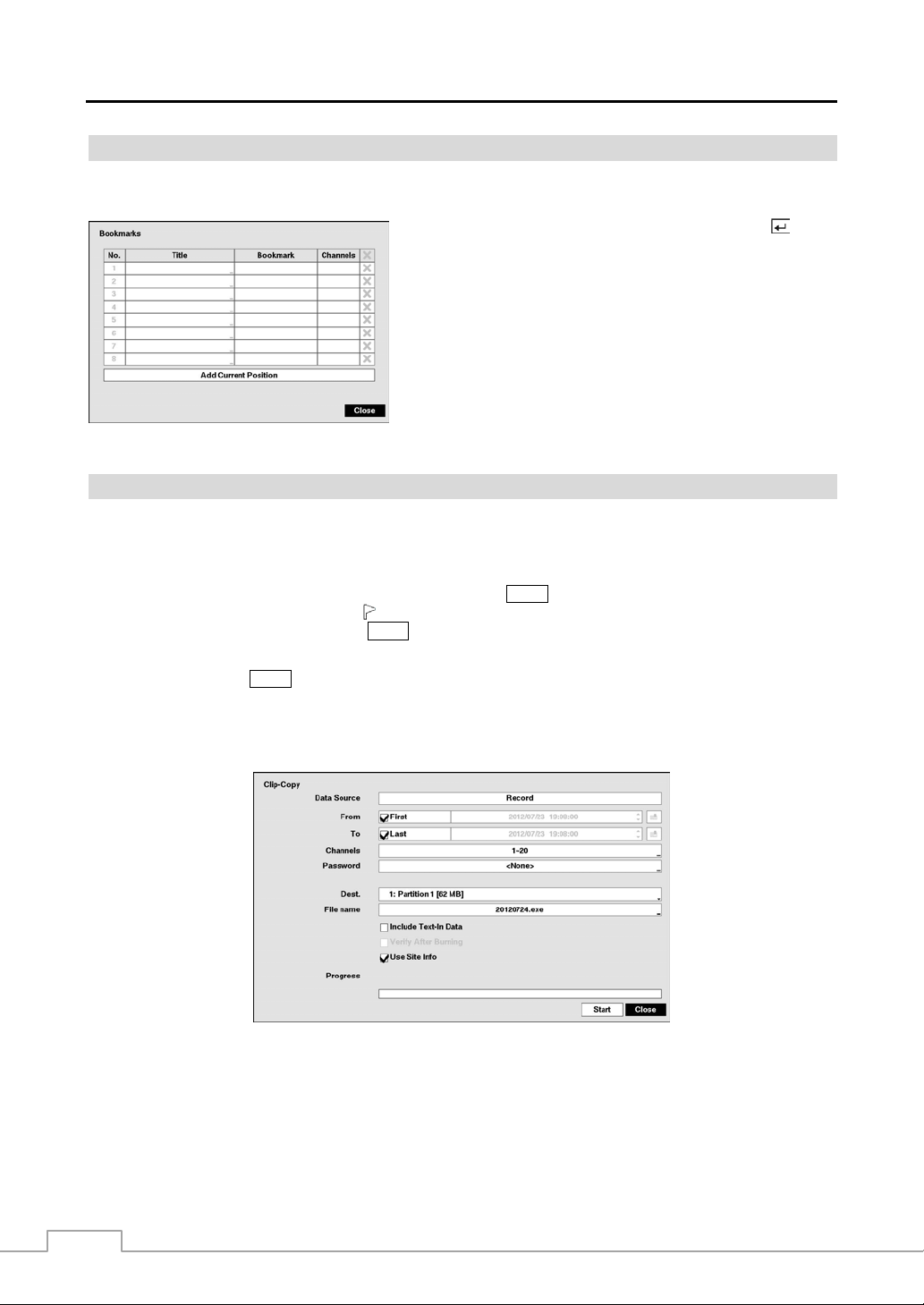
Operation Instruction
Bookmarks
The Bookmarks screen can also be accessed by selecting Bookmark in the Search – Go To menu.
Highlight the Add Current Position box and press the button
to add the current playback point to the bookmark list. Highlight
the Title box and enter the name of the registered bookmark. Use
the virtual keyboard to enter the bookmark name.
NOTE: Up to eight bookmarks can be registered.
Use the arrow buttons to highlight the bookmark point for which
you would like to see video. The selected bookmark will display
on the screen. The playback controls on the R ecord Table S earch
screen, and Jog and Shuttle on the front panel can now be used to
review the surrounding video.
Figure 53 : Bookmarks screen.
Clip-Copy
Video clips can be copied on an internal DVD RW drive, or external USB hard disk or flash drive. The copied video
clips can be viewed on computers running Microsoft Windows 2000, XP, Vista or 7. Refer to the Appendix – USB
Hard Disk Drive Preparation for information on preparing the external drive for clip copy.
Selecting EZ Copy in the Search – Export menu or pressing the COPY button during playback will set the starting
point of the video to be clip copied, and the
in the Search – Export menu or pressing the
by displaying the Clip-Copy screen.
Pressing and holding the COPY button for more than three seconds while in the Search mode initiates the One-Touch
Clip Copy function. The last recorded im age will be the ending point of video to be clip copied, and the system will
automatically begin to calculate the possible video data size that the selected storage media can handle.
Select Clip-Copy in the Search – Export menu, and the Clip-Copy screen appears to allow clip copy setup.
icon displays at the bottom-left corner of the screen. Selecting EZ Copy
COPY button again will set the ending point of the video to be clip copied
Figure 54 : Clip-Copy screen.
The Data Source box displays the source from which you make a video clip copy. The data source can be selected
from Record or Archive in the Search menu.
You can search video from the first to last recorded images, or you can set the start and stop times and dates.
78
Page 87

Digital Video Recorder
Highlight the box beside From and press the
a specific Date and Time. When set to On, the search will be from the first recorded image. When highlighting
pressing the button the bookmark list displays and the bookmark point you selected will be the starting date and time.
button to toggle between On and Off. When set to Off, you can enter
and
Highlight the box beside To and press the button to toggle between On and Off. When set to Off, you can en ter a
specific Date and Time. When set to On, the search will be to the last recorded image. When highlighting
the button the bookmark list displays and the bookmark point you selected will be the ending date and time.
and pressing
Highlight the box beside Channels and press the button. You can select the cameras that you would like to include
in your video clip.
NOTE: The channel numbers 1 to 16 are local camera channels and 17 to 20 are network device channels.
Highlight the box beside Password and press the button. A virtual keyboard appears allowing you to enter the
password for reviewing the video clips.
Highlight the box beside Dest. and press the button. You can select the storage device on which you would like
to record the video clip. You can choose from Internal DVD RW and USB Storage.
CAUTION: The USB device for clip copy must be FAT 16 or FAT32 format.
NOTE: While copying video clips on the DVD RW, the recording speed might decrease.
When the error message “Firmware update of the opti cal d riv e is requi red” disp lay s, update th e fi rm ware
of the installed DVD RW drive. Please follow the instructions described in Chapter 3 – Configuration –
System Setup section.
The DVR automatically assigns a file name to the video clip. However, you can give the video clip file a different name.
Highlight the box beside File Name and press the
button. A virtual keyboard appears. Enter a file name for the
video you are backing up and select Close. The DVR will automatically add the camera number (for exam ple “01”)
and “.exe” to the file name.
NOTE: When naming a file, you cannot use the following characters: \, /, :, ;, *, ?, !, “, <, >, |.
Highlight Include Text-In Data and press the button. This will toggle between On and Off. When this feature is
On, you can include text-in data when copying video if the video was recorded with text-in data.
Highlight Verify After Burning and press the button. This will toggle between On and Off. When this feature is
On, you can verify that the data is written on the DVD RW properly.
Highlight Use Site Info and press the button. This will toggle between On and Off. When this feature is On, you
can add the site name to the file name for the video you are backing up.
NOTE: When the site name is added to the file name, some special chara cte rs (\, /, :, ;, *, ?, !, “, < , >, |) in th e site
name will be converted to “_”.
Once you have given the video clip a file name, highlight the Start button and press the button. The confirmation
screen displaying data size will appear. When the storage device does not have enough space, the DVR will ask if you
want to copy as much of the video clip as possible in the available space. Highlight the Continue button and press
button to continue clip copy.
the
Once the clip copy starts, you can cancel it by selecting Cancel or hide the screen by selecting Close. When selecting
Close, Clip Copy continues and a confirmation screen will display when complete.
NOTE: Only 4.7GB DVD media is available. To clip copy video on DVD media using remaining space, the size
of previously recorded data on the DVD media should be less than 4GB.
Select the Full Erase option when erasing recorded data on DVD media, otherwise the media will not
operate properly when rewritten.
The file size for clip copy is limited to 30GB. When copying video clips larger than 2GB, the video clips
will be save in units of 2GB. For example, 3 individual 2GB files will be created when saving a 6GB video
clip. However, the file size for the One-Touch Clip Copy is limited to 2GB.
You can use other functions on the DVR while video is being backed up. To do this, high light th e Close button an d
press the button. You can return to the Clip-Copy screen at any time to check the progress.
79
Page 88

Operation Instruction
You do not need to install any special software on your personal computer to review the video clips. Refer to Speco
Central Operation Instruction for instructions on how to review video clips you have copied.
NOTE: During Clip Copy, you cannot shut the system down, clear data on the storage device, or format the
storage device.
CAUTION: Do NOT disconnect the USB cable or the power from the external drive while copying
video clips. If the external drive is shut down or the USB cable is disconnected while
copying video clips, THE DVR SYSTEM MAY NOT WORK NORMA LLY OR THE EXTER NAL
DRIVE COULD BE DAMAGED, and you will get an error message the next time you try
to copy video clips. You will need to power down the DVR and restart it to get rid of the
error message. Once the file system of the USB hard disk drive has been corrupted, this
error message cannot be dismissed. Even after restarting the DVR it may automatically
restart while preparing to clip copy. You must recover the file sy stem using the rec overy
program, or you must reformat the hard disk drive.
Print
You can print images on a printer. Connect a PostScript™ printer, or external hard disk drive or flas h drive to one of
the USB ports.
Highlight the box beside Printer Model and press the
button. Selecting
PostScript Printer will print images on a PostScript™ printer connected to
the DVR. Selecting File Printer will save the current image as a PDF file
on an external USB hard disk drive or flash drive.
NOTE: Images saved as PDF files can be printed on any printer connected
to your PC.
Highlight the box beside Paper Size and press the button. You can select
the paper size.
Figure 55 : Print screen.
Once you have selected the printer model and paper size, highlight the Print button and press the
appears asking you if you want to print the current image. Highlight the Continue button and press the button to print.
NOTE: If your printer only supports an LPT connection (parallel), u se an LPT to USB converter c able. The print er
cable is not provided.
button. A message
Disk Mirroring
The DVR supports disk mirroring to prevent unexpected loss of recorded video data that might be caused by disk damage
or corruption. You can set up disk mirroring by highlighting Storage in the System menu and pressing the
button.
80
Page 89

Digital Video Recorder
r
Figure 56 : System – Storage setup screen.
You can enable mirroring between two disks by designating the source disk and the destination disk from a list of internal
hard disk drives. Up to two Mirrors are supported.
Highlighting the boxes under Source and Dest. and pressing the button allows you to select the source disk and
the destination disk for the selected Mirror.
NOTE: The source disk can be designated only from devices formatted for recording.
A device formatted for archiving cannot be used for disk mirroring.
The capacity of the destination disk should be the same or higher than the source disk for proper mirroring
between the two disks.
CAUTION: Any existing data on the Destination Disk will be erased once it is designated as a mirror
destination disk.
Highlighting Start and pressing the
button displays a confirmation screen asking you to confirm whether or not you
want to start mirroring the selected disk. Once you start mirroring, the two disks will be resynchronized. Any data on
the destination disk will be erased, and th e data on the sour ce disk will be copied to the d estination disk. If the source
disk is formatted and has no data, the disks will not be resynchronized. Resynchronization takes about 40 minutes per
each 10GB of capacity. After resynchronization is complete, disk mirroring (writing data on the two disks at the same
time) will start.
Once disk mirroring starts, you can cancel it by highlighting Stop and pressing the button. Selecting Stop displays
a confirmation screen asking you to confirm whether or not you want to stop mirroring for the selected disk.
NOTE: Once disk mirroring stopped, the destination disk will be set to Not Used. If resynchronizatio n has be en
finished, the destination disk cannot be used for re cording o r archiv ing, but it ca n be us ed for search ing.
If you want to use the disk for recording or archiving, you must reformat it.
CAUTION: Disk mirroring will NOT automatically restart from an interrupted state. Once mirroring
is stopped, you must restart it by following the mirroring setup procedures.
CAUTION: If disk mirroring fails, you must
estart the system before trying disk mirroring again.
When a disk mirroring failure is caused by a disk error, you must replace the disk with
a new one.
81
Page 90

Operation Instruction
82
Page 91

Digital Video Recorder
Appendix
USB Hard Disk Drive Preparation
NOTE: The following description is for preparing a USB hard disk drive under Windows 2000. Preparing a USB
NOTE: The partition size should be less than 32GB because of Microsoft limitations.
1 2 3 4 5 6
123456789012345678901234567890123456789012345678901234567890
Item Unit price Qty amount
==================================================
Coke | $ 2.20 | 1(s) | $ 2.20
Fanta | $ 2.20 | 1(s) | $ 2.20
Hotdog | $ 3.50 | 3(s) | $ 10.50
Pepsi | $ 1.95 | 1(s) | $ 1.95
==================================================
total : $ 16.85
Thank you~~
In the above text-in data, you can find that the comparison value is located at 17th (Unit price, $ mark will be ignored
automatically), 28th (Qty) and 40th (amount) characters (including spaces) from the left. In this case, you can enter
“17”, “28” and “40” in each Column box.
For example, if you want to search for Coke with a Qty (Quantity) of more than 1 and Hotdog with an amount totaling
over $8, the following search condition can be set.
hard disk drive under Windows XP, Window Vista and Window 7 is almost identical to Windows 2000.
1. Connect the USB hard disk drive to your computer using the USB Cable.
2. Turn on your computer.
3. The USB device icon should display on the Taskbar.
4. If the USB hard disk drive is partitioned or has data, it will show up in My Computer as a hard disk drive
icon. Check the file system by right clicking on the icon and checking under Properties > General > File
System. If the file system is NOT FAT32 format, format the USB hard disk drive using the FAT32 format.
5. If the USB hard disk drive is not partitioned, go to Administrative Tools in Control Panel and launch Computer
Management. Open Disk Management in Storage and right click an unallocated region of the USB hard
disk drive. Then, click Create Partition.
6. In the Create Partition wizard, click Next then Primary Partition, and follow the instructions on the screen.
Make sure that the FAT32 is selected for the file system.
After formatting is complete, the USB hard disk drive will be added to My Computer.
7. Connect the USB hard disk drive to the DVR.
Text-In Search Examples
Search Example I
83
Page 92

Operation Instruction
Search Example II
1 2 3 4 5 6
123456789012345678901234567890123456789012345678901234567890
Item Unit price Qty amount
==================================================
Coke | $ 2.20 | 1(s)
$ 2.20
Fanta | $ 2.20 | 1(s)
$ 2.20
Hotdog | $ 3.50 | 3(s)
$ 10.50
Pepsi | $ 1.95 | 1(s)
$ 1.95
==================================================
total : $ 16.85
Thank you~~
In the above text-in data, you can find that the comparison value is located at 17th (Unit price, $ mark will be ignored
automatically), 28th (Qty) and 40th (amount) characters (including spaces) from the left, but the value of amount
category is located on a different line from Item . In this case, you can enter “17”, “2 8” and “40” in each Column box
and enter “1” in the Line box for the next line.
For example, if you want to search for Coke with a Qty (Quantity) of more than 1 and Hotdog with an amount totaling
over $8, the following search condition can be set.
84
Page 93

Digital Video Recorder
Speco Remote
Speco Remote allows you to access a remote DVR, monitor live video images and search recorded video using Internet
Explorer web browser anytime from virtually anywhere.
Computer system requirements for using the Speco Remote program are:
Oper ating Syste m: Microsoft
Microsoft
CPU: Intel Pentium III (Celeron) 600MHz or faster
RAM: 128MB or higher
VGA: 8MB or higher (1024x768, 24bpp or higher)
Internet Explorer: Version 6.0 or later (32 Bit)
®
Windows® 7 (Home Premium, Professional, Ultimate) or Microsoft® Windows® 8 (Pro, Enterprise)
Start Internet Explorer on your local PC. You can run the Speco Remote program by entering the following information
in the address field.
– “http://IP address:port number” (The DVR IP address and the Speco Remote port number (default: 12088) set in the
Network setup screen (General tab))
– Or, “http://DVRNS server address/DVR name” (The DVRNS server address and the DVR name registered on the
DVRNS server)
NOTE: You will need to get the appropriate IP address for the DVR you want to connect to and the Speco Remote
port number from your network administrator.
Speco Remote only works with Microsoft Internet Explorer and will NOT work with other browsers.
Speco Remote does not work in Microsoft
®
Windows® XP (Service Pack 3), Microsoft® Windows® Vista (Service Pack 1),
®
Windows® 8 metro UI.
Select between the Re mote Watch (Web monitoring) and Remote Search
(Web search) modes. Entering ID and PASSWORD and clicking the
[LOGIN] button logs in using the selected mode.
NOTE: Do NOT close the LOGIN window during the Speco Remote operation, otherwise, it will cause a script
error when switching between Web monitoring and Web search modes, and you will need to restart the
Speco Remote program.
When running the updated Speco Remote for the first time, Internet Explorer might occasionally load
the information of the previous version. In this case, delete the temporary internet files by selecting
Tools Internet Options General tab, and then run Speco Remote again.
There might be a problem that the bottom of Speco R emote page i s cropped due to the add ress or status
bars. In this situation, it is recommended that websites open windows without address or status bars
by changing the internet setting. (Go to the Tool s Internet Options Security tab Click the Cust om
level… button Select Enable for the Allow webs it es to op en windows without address or st atu s ba rs
option)
When running Speco Remote in the Microsoft Windows Vista or higher operating system, it is recommended
to start Internet Explorer with elevated administrator permissions. Click the right mouse button on the
Internet Explorer icon and select the Run as administrator op ti on fr om the con text menu. Otherwise,
some functions of the Speco Remote might be limited to use.
85
Page 94

Operation Instruction
NOTE: There might be a problem with screen display or screen update due to low image transmission speed
when using the Microsoft Windows Vista or higher operating system. In this situation, it is recommended
that you disable the Auto Tuning capability of your computer.
Run the Command Prompt with elevated administrator permissions (Go to the Start Menu →
Accessories → Command Prompt → Click the right mouse button and select the Run as admini strator
option). Then enter “netsh int tcp set globa l autotuni nglev el=disable” and hit the ent er key. Re start
your computer to apply the changes.
If you want to enable the Auto Tuning capability again, enter “netsh int tcp set global autotuninglevel=
normal” after running the Command Prompt with elevated administrator permissions. Restart your
computer to apply the changes.
Web Monitoring Mode
Remote Watch is a remote web monitoring program that allows you to monitor live video transmitted in real-time from
the remote DVR.
① Click the
② Click the to access to the web search mode.
③ Position the mouse pointer on the Remote Watch logo to see the version of the Speco Remote program.
④ The DVR information window displays the login information of Speco Remote.
to log out the Speco Remote program.
⑤ Click the screen format to select the desired display mode. When changing the screen format, the selected camera
on the current screen will be located in the first cell of the new layout.
⑥ Click the camera button to select the camera to be viewed.
⑦ Click the to adjust the brightness, contrast, saturation and hue of monitoring image.
⑧ Click the
⑨ Click the to control alarm out devices at the remote site.
86
to control pan, tilt and zoom of the camera from a remote site.
Page 95

Digital Video Recorder
⑩ Click the
to set up the image drawing mode, OSD display and beep on/off. You can adjust the display speed
by changing the image drawing mode, select OSD information to be displayed on the screen, and turn the DVR’s
internal buzzer on and off from a remote site.
⑪ Click the to save the current image as a bitmap or JPEG file format.
⑫ Click the to change the setup of the remote DVR.
⑬ The event status window at the bottom displays a list of events that were detected from the remote site.
⑭ Selecting a camera on the screen and clicking the right mouse button displays the text menu screen.
Change Camera Title: Changes the camera name.
Enable Audio: Enables audio communication with the remote site. When the
audio control panel displays, click the
site and click the button again to stop sending audio. Click the
to send audio to the connected remote
to monitor live
audio from the connected remote site through the attached speaker and click th e
button again stop monitoring live audio. Clicking both and allows two-way
communication. Clicking the
disables audio communication.
Aspect Ratio: Changes the image aspect ratio.
Anti-Aliasing Screen: Enhances image display quality by eliminating stair
NOTE: A camera name change in the Remote Watch mode does not affect the camera name set up on the remote
site. Leaving the Camera Title blank causes the camera name set up on the remote site to display.
The
icon will display on each camera screen when audio communication is available between the
Speco Remote system and a DVR.
stepping (aliasing) effects in the enlarged image.
Web Search Mode
Remote Search is a remote web search program that allows you to search recorded video on the remote DVR.
NOTE: The remote site connection in the Remote Search mode will automatically be disconnected if there is
no activity for 30 minutes.
① Click the
② Click the to access to the web monitoring mode.
③ Position the mouse pointer on the Remote Search logo to see the version of the Speco Remote program..
to log out the Speco Remote program.
87
Page 96

Operation Instruction
④ The DVR information window displays the time information of recorded data on th e remote DVR and login information
of Speco Remote.
⑤ Click the to blur, sharpen, equalize and interpolate playback images. Click the to zoom
out or zoom in the recorded image. Click the to adjust the brightness of the recorded images.
NOTE: Image processing works only in the pause mode.
⑥ The playback function buttons include fast backward, pause, play, fast forward, go to the first
image, go to the previous image, go to the next image, and got to the last image.
⑦ Click the screen format to select the desired display mode.
⑧ Click the to enter the time-lapse search mode which allows you to search for recorded data by
time and then play back images found within the time parameters. The Timetable window located
at the bottom displays the time information for the image of the date selected on the calendar.
If more than one video stream in the same time range, you can select the video stream you want
to search. Clicking a specific time displays the image recorded at that time on the screen. Selecting
allows you to display an image from a specific time.
the
⑨ Click the to enter the event search mode which allows you to search for event log ent ries using sp ecific conditions
and play back the images associated with those event entries.
⑩ Click the to set up the image drawing mode and OSD display. You can adjust the display speed by changing
the image drawing mode, and select OSD information to be displayed on the screen.
⑪ Click the to save any video clip of recorded data as an executable file, or click the to save the current image in
a bitmap or JPEG file format. Click the
⑫ Click the to reload the recording data.
⑬ The Timetable displays recorded data of the selected camera by time (in hour segments).
⑭ Selecting a camera on the screen and clicking the right mouse button displays the text menu screen.
to print the current image on a printer connected to your computer.
Change Camera Title: Changes the camera name.
Enable Audio: Plays audio while playing back recorded video that has recorded
audio. (Single-Screen Layout Only)
Aspect Ratio: Changes the image aspect ratio.
Anti-Aliasing Screen: Enhances image display quality by eliminating stair
NOTE: A camera name change in the Remote Search mode does not affect the camera name set up on the remote
site. Leaving the Camera Title blank causes the camera name set up on the remote site to display.
stepping (aliasing) effects in the enlarged image.
Time Overlap
If the DVR’s time and date have been reset to a time that is earlier than the existing recorded video, it is possible for
the DVR to have more than one video stream in the same time range. In this case, you can search overlapping video
streams individually by selecting a specific segment. For example, when the DVR has recorded video from one to
five o’clock and the user changes the tim e backward from five to three o’ clock and th en continues re cording until six
o’clock, there will be two video streams and segments from three to five o’clock.
You can search overlapping video streams by selecting a specific time or time range. If you want to search recorded
video at four o’clock during the overlapping time range using a sear ch menu such as Go to the Date/Time, select the
segment you want to search.
88
Page 97

Digital Video Recorder
If you want to search recorded video from four to five o’clock during the overlapping time range usi ng a search menu
such as Event Log Search, Text-In Search or Motion Search, it is possible for the DVR to have two overlapping
start and stop times. You will be asked to select one of the overlapping start and stop times from the search time ranges
as follows:
From four o’clock of the first segment to five o’clock of the first segment
From four o’clock of the first segment to five o’clock of the second segment
From four o’clock of the second segment to five o’clock of the second segment
Remote Setup of Network Devices
The following describes how to set up the network devices using the ONVIF
While in the Live Monitoring mode, pr ess the
MENU button and move to the Camera menu and then to Network Camera
setup. In the Network Camera setup screen, highlight the box under the Settings heading and press the button.
TM
Conformance protocol on the DVR.
Highlight the Device Remote Setup box and press the
NOTE: The setup menu and options may differ depending on the device model. Refer to the network device
manufacturer’s documentation for correct device settings.
button. The Device Remote Setup screen appears.
89
Page 98

Operation Instruction
System Setup
Information: Displays the device information.
Maintenance: Restarts the device or returns all device settings to the original factory settings.
Security Setup
User: Adds or deletes a user.
Media Setup
90
ONVIF Profile: Adds or deletes an ONVIF
TM
profile.
Video: Sets up the video source and encoder. The
frame rate cannot exceed 15 ips when recording video
with the H.264 codec and 4CIF resolution if the device
is a network video transmitter.
Audio: Sets up the audio source and encoder.
Page 99

Network Setup
Digital Video Recorder
I/O Setup
TCP/IP: Sets up the device’s IP address and DNS server .
DDNS: Sets up the DDNS function.
Zero Configuration: Automatically allocates an
appropriate IP address for the current network co nditions
(supported only for devices that provide the function).
Network Protocol: Changes the port numbers for the
network protocols that are used in the device (supported
only for the protocols that are used in the device).
WS-Discovery: Sets up the WS-Discovery function.
I/O: Sets up the input and output devices.
91
Page 100

Operation Instruction
PTZ Setup
Connector Pin Outs
I/O Connector Pin Outs
PTZ: Sets up the PTZ.
AI (1 to 16)
GND
NC
C
NO
ARI
RS485 Connector Pin Outs
Master Unit Slave Unit
Alarm Inputs 1 to 16
Chassis Ground (5 connectors)
Relay Alarm Output (Normally Closed)
Relay Common
Relay Alarm Output (Normally Open)
Alarm Reset In
+
− To
To TX+/ RX+
TX-/ RX-
92
 Loading...