

Page 1

1
Printable manuals available at:
www.specialized.com
(click on: support tab)
Page 2

2
Components of the Speedzone Comp 3
Installing Computer Mounts 4
Installing speed & cadence transmitter 5
Speedzone Comp user interface 6
Easy set-up and resetting 7
Using your Speedzone Comp (keyow) 15
Re-entering the pairing sequence 16
Re-entering calibration sequence 17
Clearing TRIP/ATM (Auto Timer) 18
Selecting Bike #1 - #2 setting 19
Re-setting the wheel/tire size 20
Manually setting wheel/tire size 21
Using the timer 23
Re-setting the clock and language 26
Heart rate zone setup 27
Setting power zones (auto or manual) 28
Replacing the battery 30
Specications and ranges 31
Speedzone Comp Terminology 33
Troubleshooting 34
Warranty information 35
Table of contents
Page 3
3
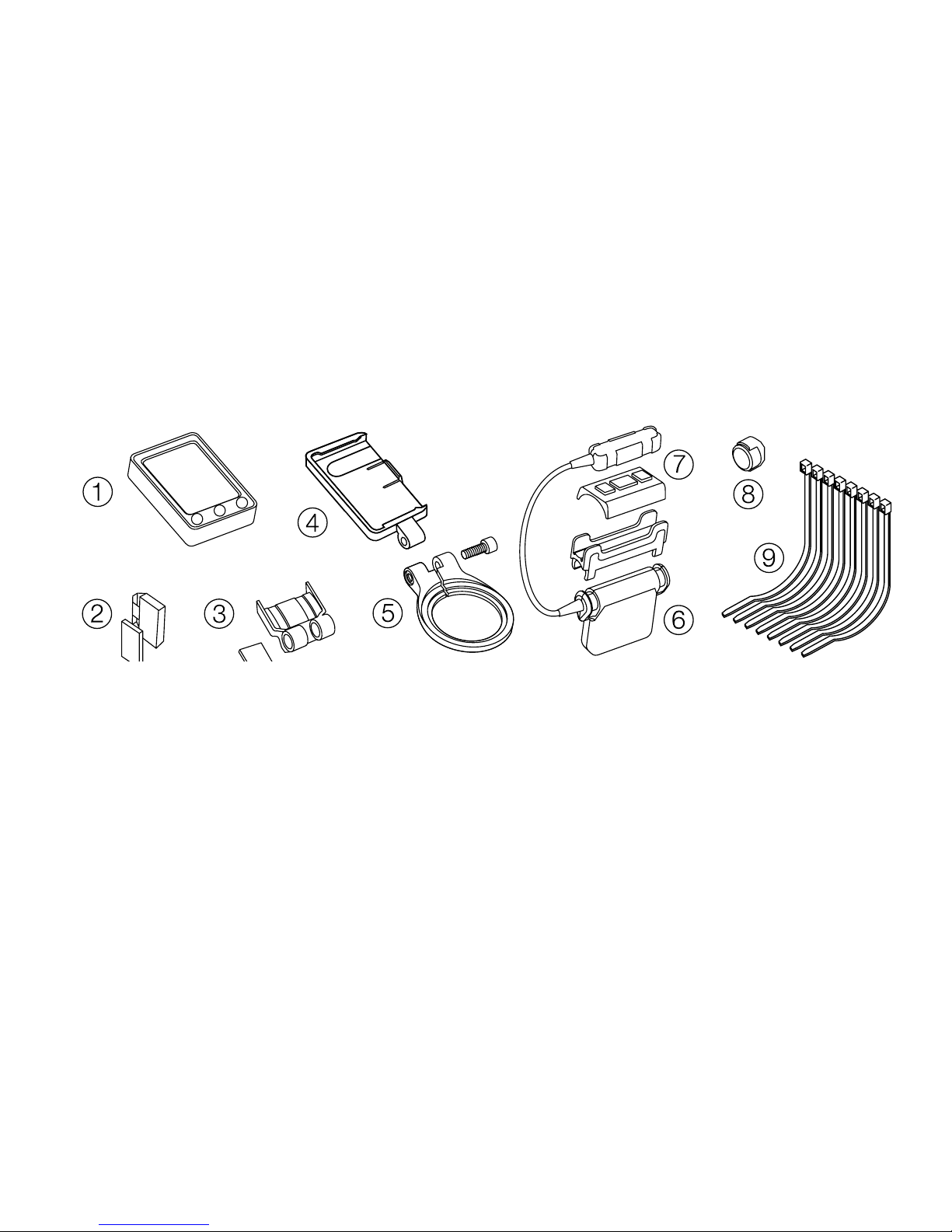
Components of the Speedzone Comp
1. Speedzone cyclocomputer head unit
2. Cadence magnet
3. Handlebar bracket
4. Base mount
5. Steerer tube bracket
6. Speed transmitter
7. Cadence sensor
8. Spoke magnet
9. Zip ties
Page 4
4
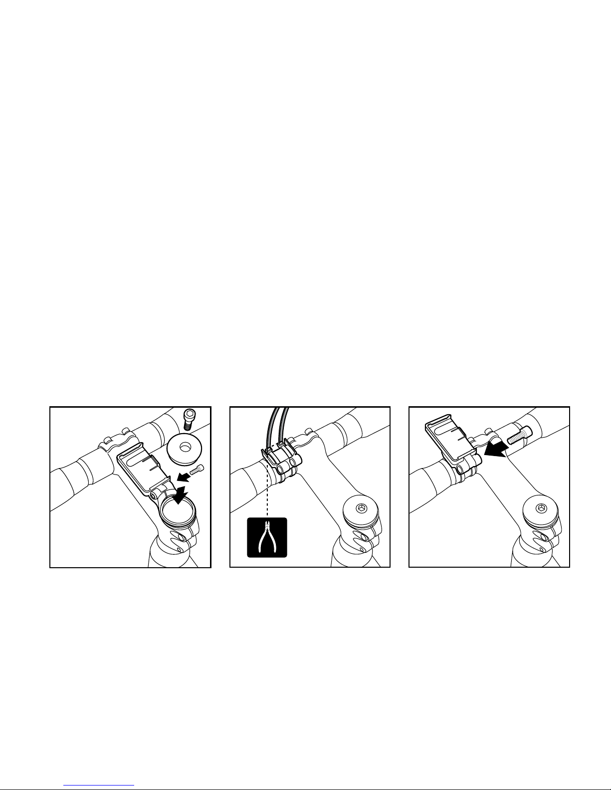
• Install the steerer tube bracket base assembly on the steerer
tube. Re-install the steerer tube top cap.
• Place handlebar bracket on handlebar, attach the base mount
to the handlebar bracket with the included bolt.
• Adjust base to desired angle with bolt adjustment.
Installing Computer Mounts
steerer tube bracket
handlebar bracket
Page 5
5
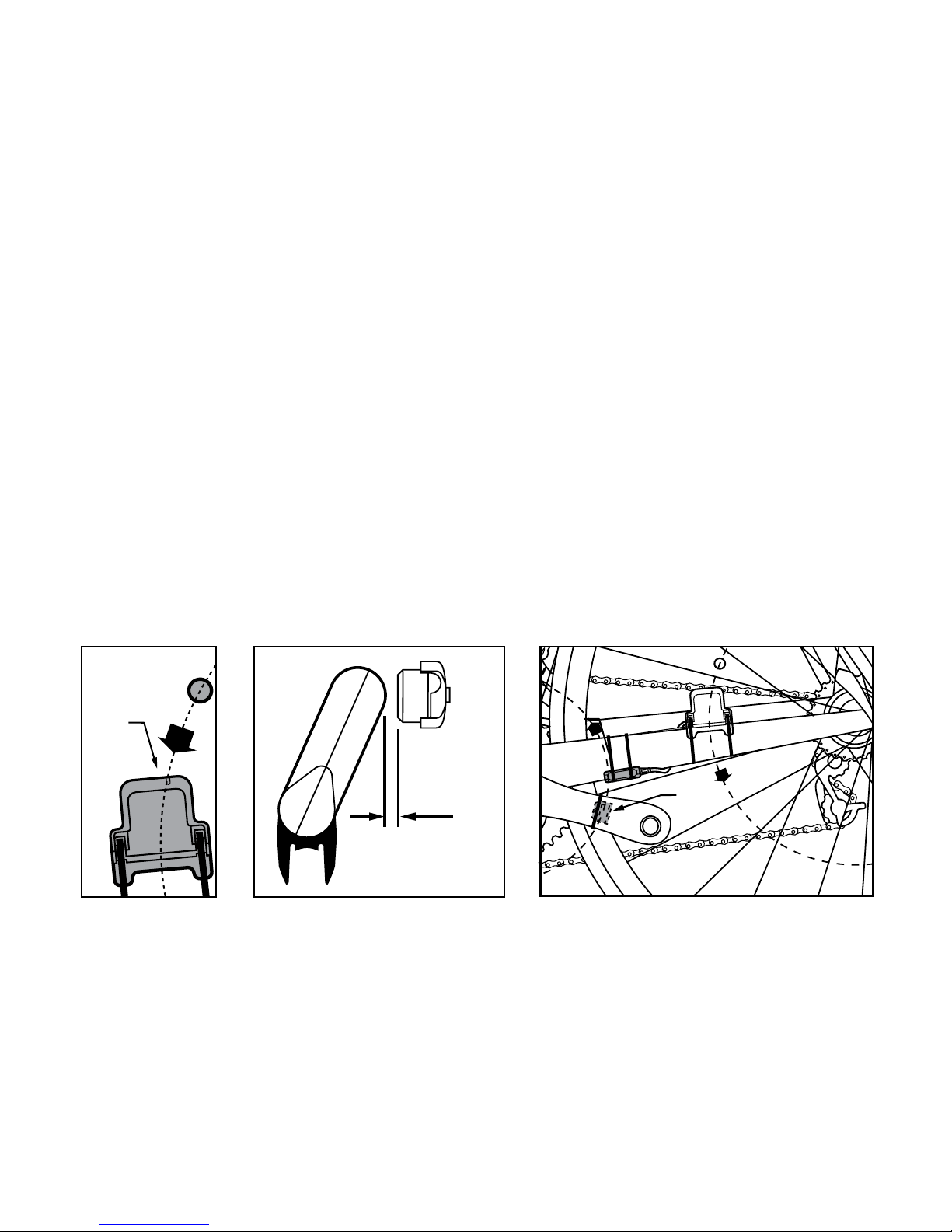
• Adjust spoke magnet so path of rotation passes along the
groove area inside the sensor. IMPORTANT: Placing magnet
outside the groove path may cause improper reading.
• Attach the cadence magnet with self adhesive pad to the
crank arm, and position the sensor’s raised line within the
magnet’s rotation path.
Installing speed & cadence transmitter
!
1-5mm
1/16 - 1/4 in.
!
Page 6
6
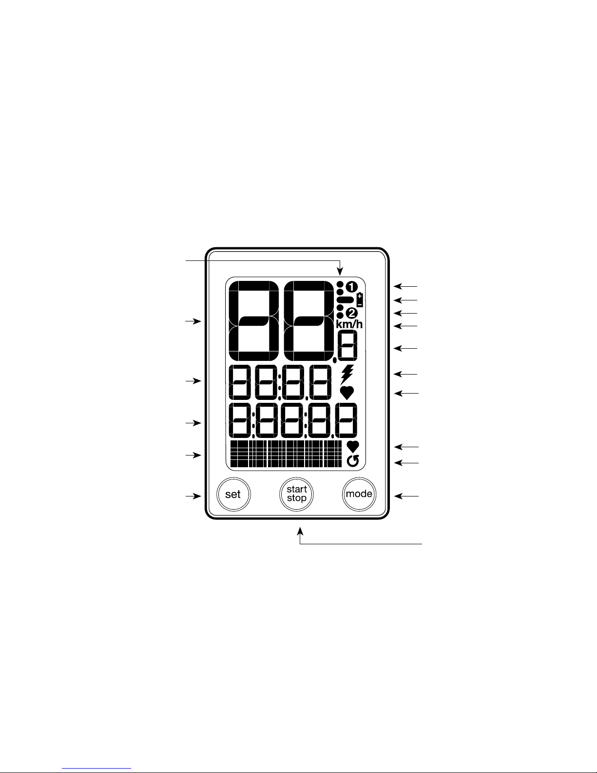
Speedzone Comp user interface
Digital Speed Display
Secondary function display
Secondary function indicator
Average speed comparator
Battery low indicator
Bike #2 indicator
Speed (10ths)
Miles (English)/KM (metric)
Set key
Mode key
Start/Stop key
Power(watts)/Heartrate(BPM)
*Cadence signal
Bike #1 indicator
*Power indicator
*Heartrate signal
*Heartrate indicator
(when power is not paired)
* Illuminated when signal is paired
Page 7

Setup
7
Easy set-up and resetting
2 sec PRESSOR
Hold “start/stop”
for 2 seconds to
initiate easy setup;
this is only required
to wake unit from
shipping mode
(rst purchased).
Wake from shipping mode Reset and all clear
Press reset button
to enter easy
set up.
Blank screen
indicates
shipping mode
Page 8
8
Setup
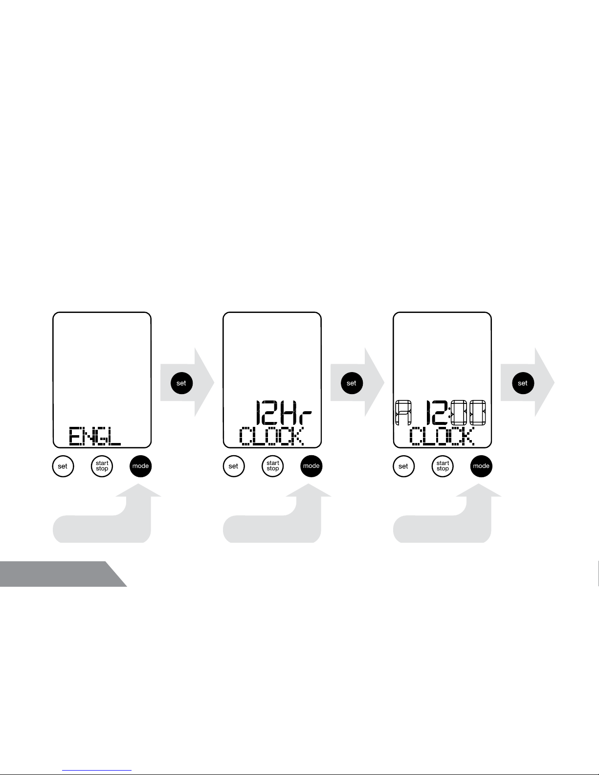
From initial start-up:
Language selection & clock setting
select language select 12/24 hr select hour
Page 9
Setup
9
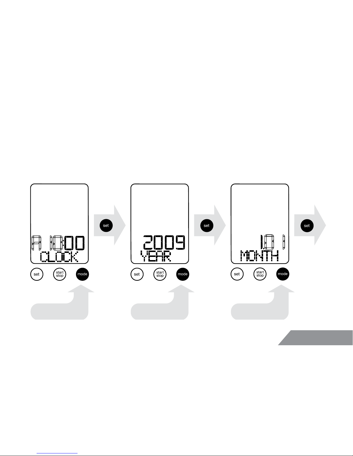
...continued clock and date setting
select minute select year select month
Page 10
10
Setup
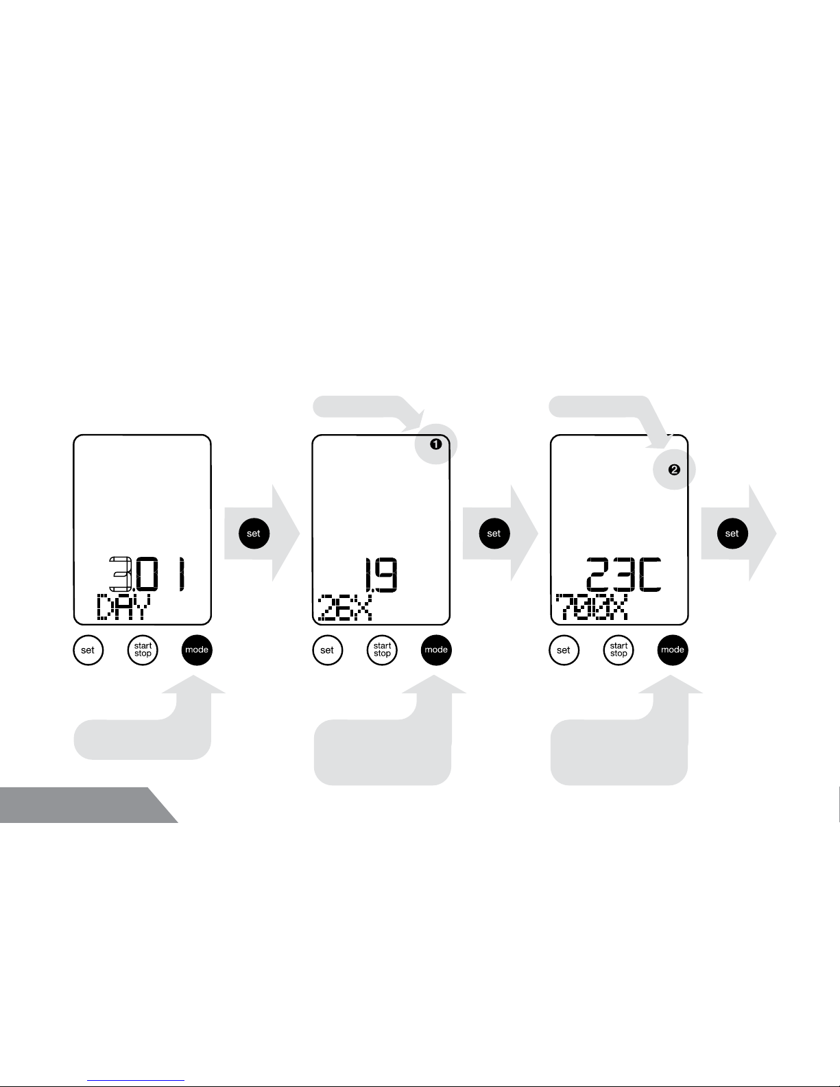
Wheel and tire size selection
select day
scroll through
wheel sizes
bicycle #1 bicycle #2
scroll through
wheel sizes for
bike #2
scroll through
wheel sizes
scroll through
wheel sizes for
bike #1
(To manually set wheel size see page 20)
Page 11
Setup
11
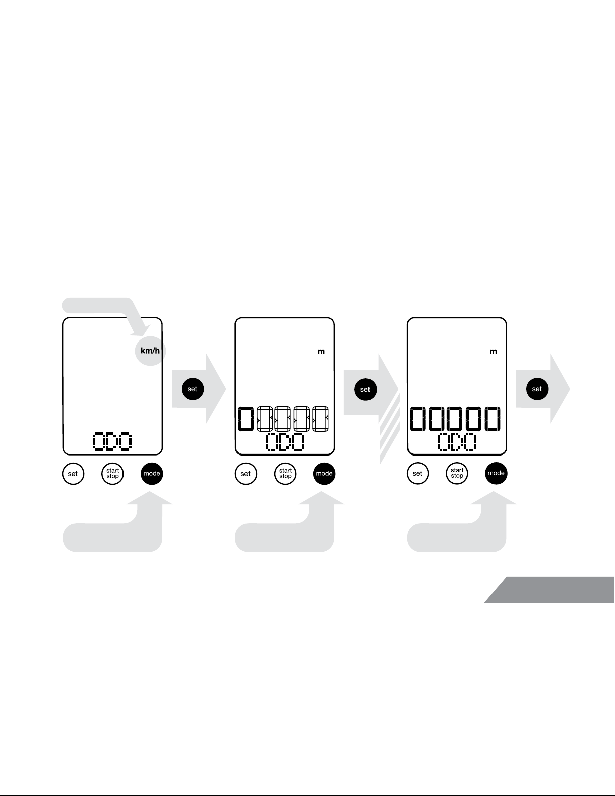
Metric (km) or English (mi) & odometer
select km / miles select digit select digit
x4
km or miles
Page 12
12
Setup
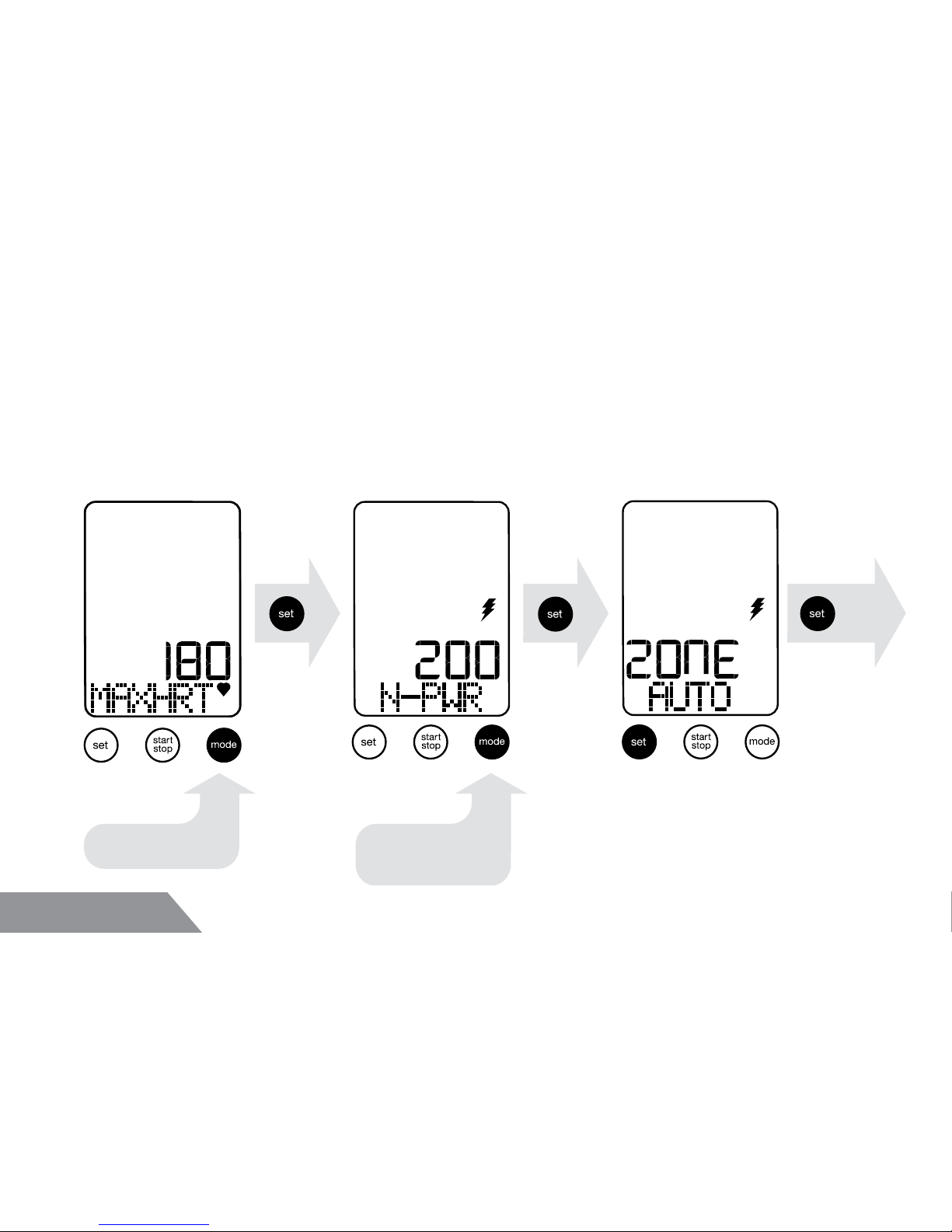
• Max heart rate guideline: 220 minus your age
• Normal power (N-PWR) = power (watts) sustained for 20-40
minutes of riding
Heart rate / normal power / power zone
enter max HR
enter normal
power
auto
To set manually see page 28
Page 13
Setup
13
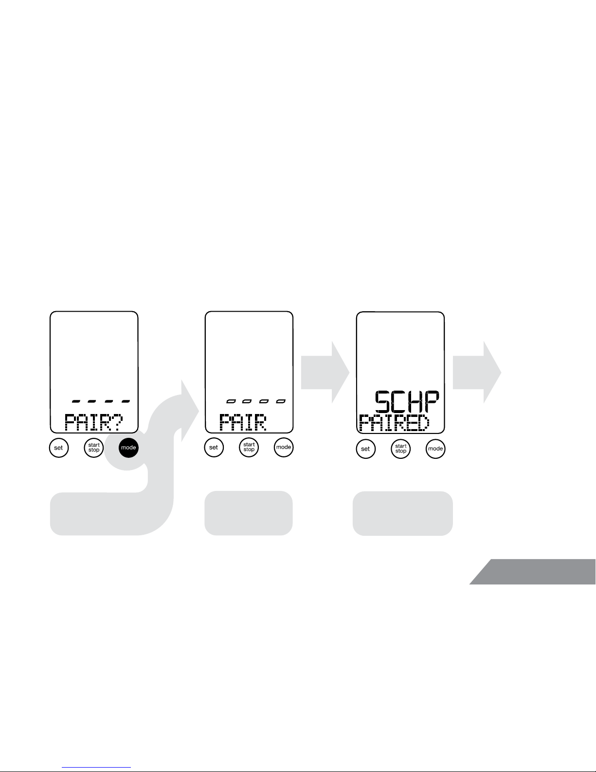
Head unit is searching for Speed, Cadence, Heart, and Power
transmission signal from ANT+ digital transmitters.
Pairing digital ANT+™ wireless device
begin signal pairing
sequence...
head unit is
searching for
digital signals
Speed / Cadence /
Heartrate / Power
PAIRED
Clock
Page 14
14
Setup
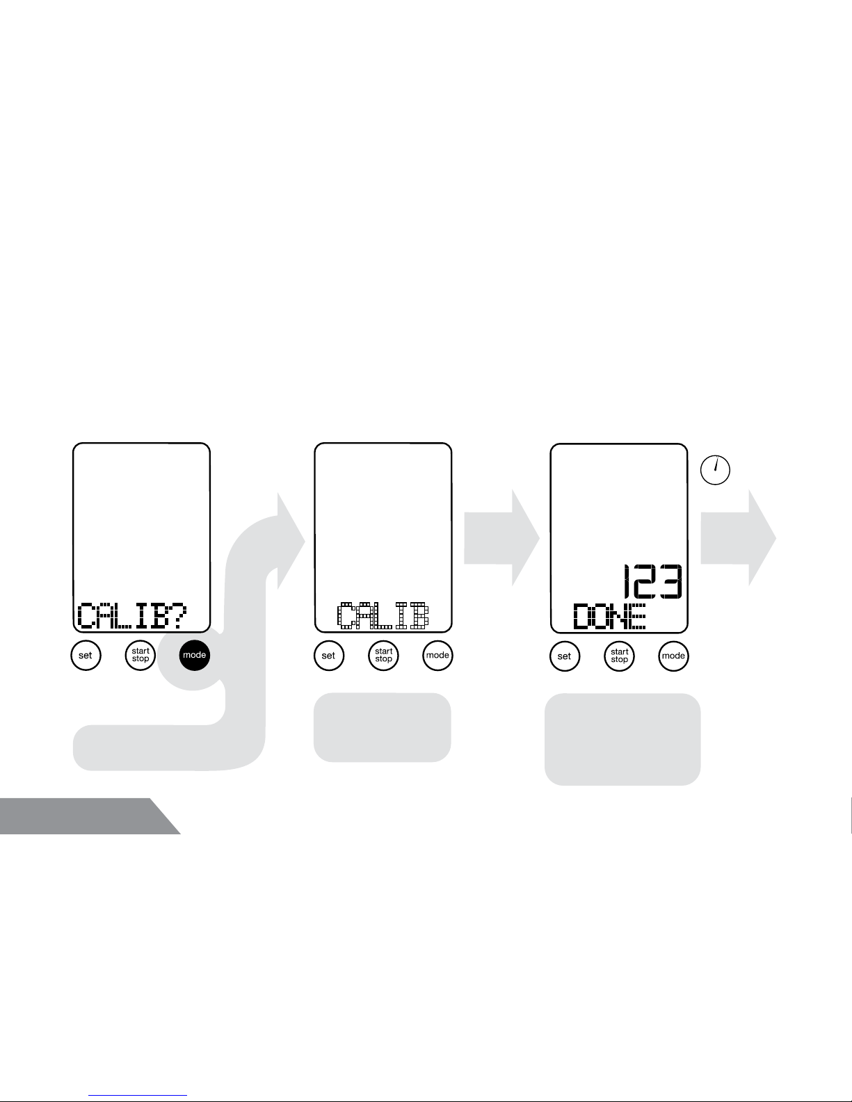
begin calibrating...
head unit is
searching for
digital signal
Power device is
calibrated
Calibration
number displayed
Clock
2 sec.
When “CALIB” is ashing follow instruction for calibrating your
specic power meter. Calibration mode will only activate when
paired with power device (see page 13).
Calibrating power devices
*Press “set” to bypass calibration and proceed to normal operation.
*
Page 15
15
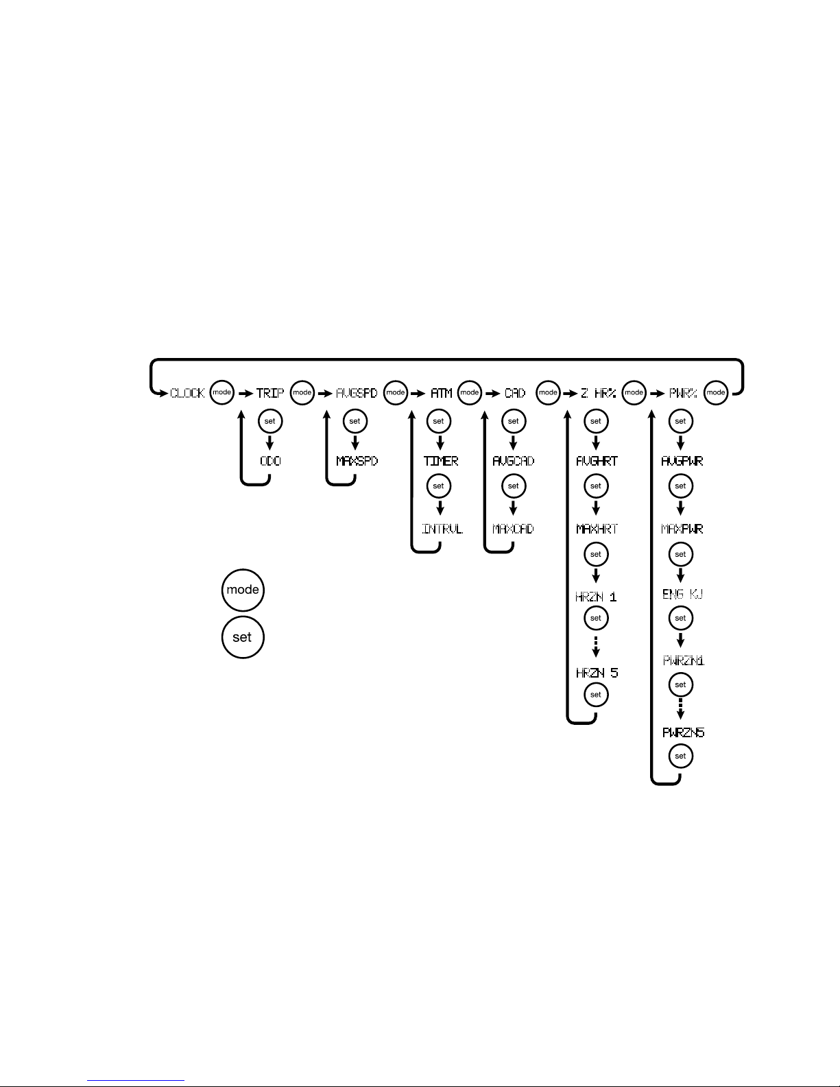
Press to access major functions
Press to access sub functions
Using your Speedzone Comp (keyow)
Page 16
16
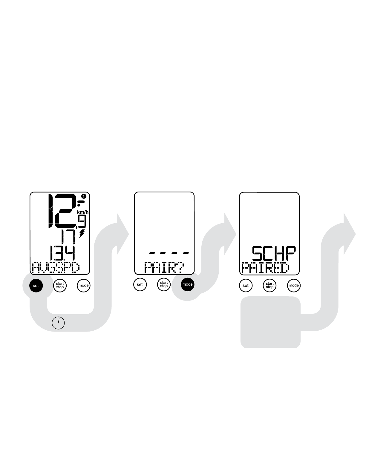
Re-entering the pairing sequence
Scroll to AVGSPD mode, and hold “set” key for 2 seconds.
Every wireless device must be ANT+ compatible device to
transmit data.
2 sec.
Head unit is
searching for
signals (see
earlier section)
S - Speed
C - Cadence
H - Heart Rate
P - Power
Page 17
17
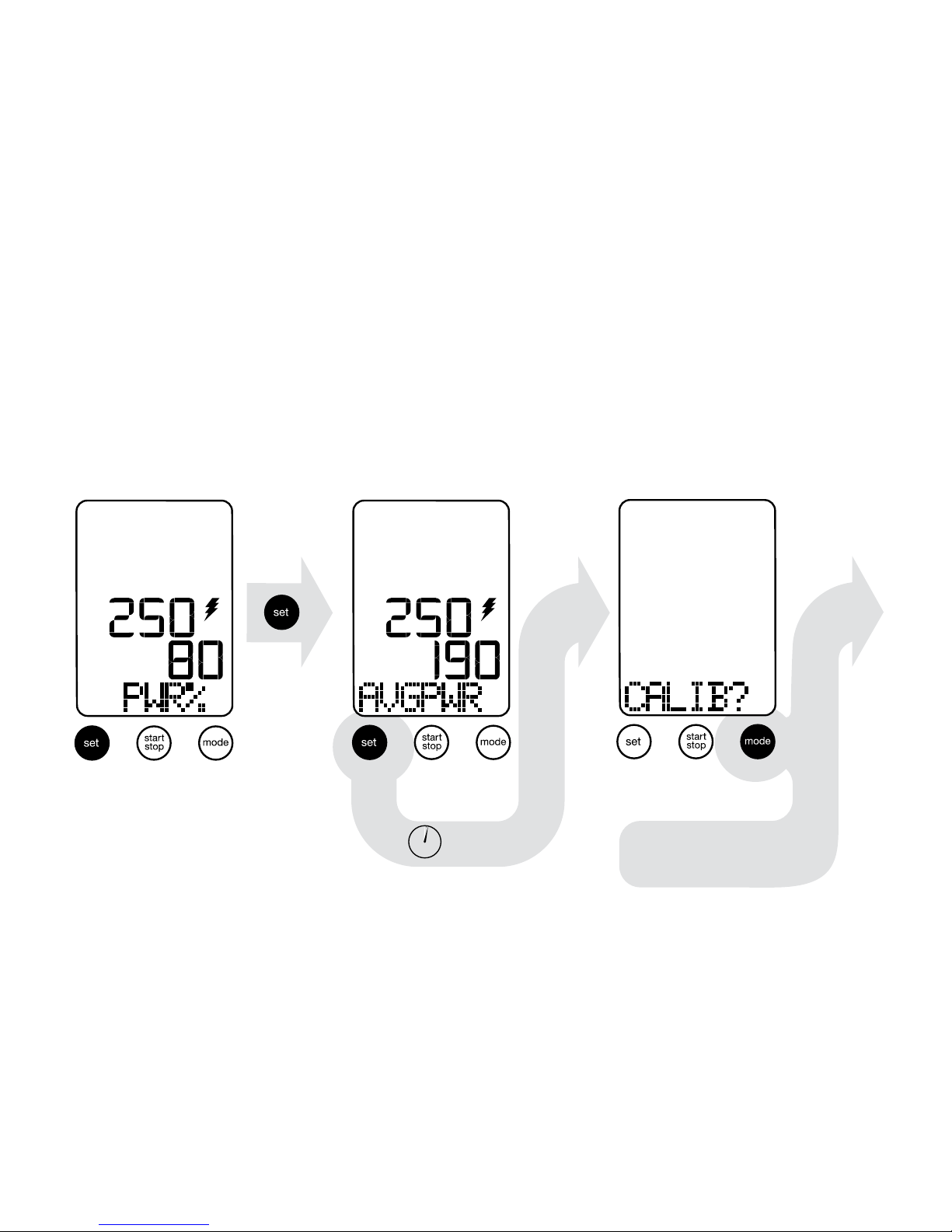
Scroll to AVGPWR mode, and hold “set” key for 2 seconds
Re-entering calibration sequence
2 sec.
begin calibrating...
(see page 14)
Page 18
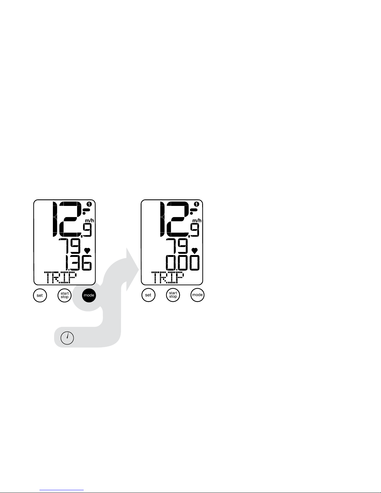
18
In “TRIP“ or “ATM“ mode, press “mode“ key for two seconds.
Resetting “TRIP“ will only clear ride shown data only and PC
download data is saved.
Clearing TRIP/ATM (Auto Timer)
2 sec.
Page 19
19
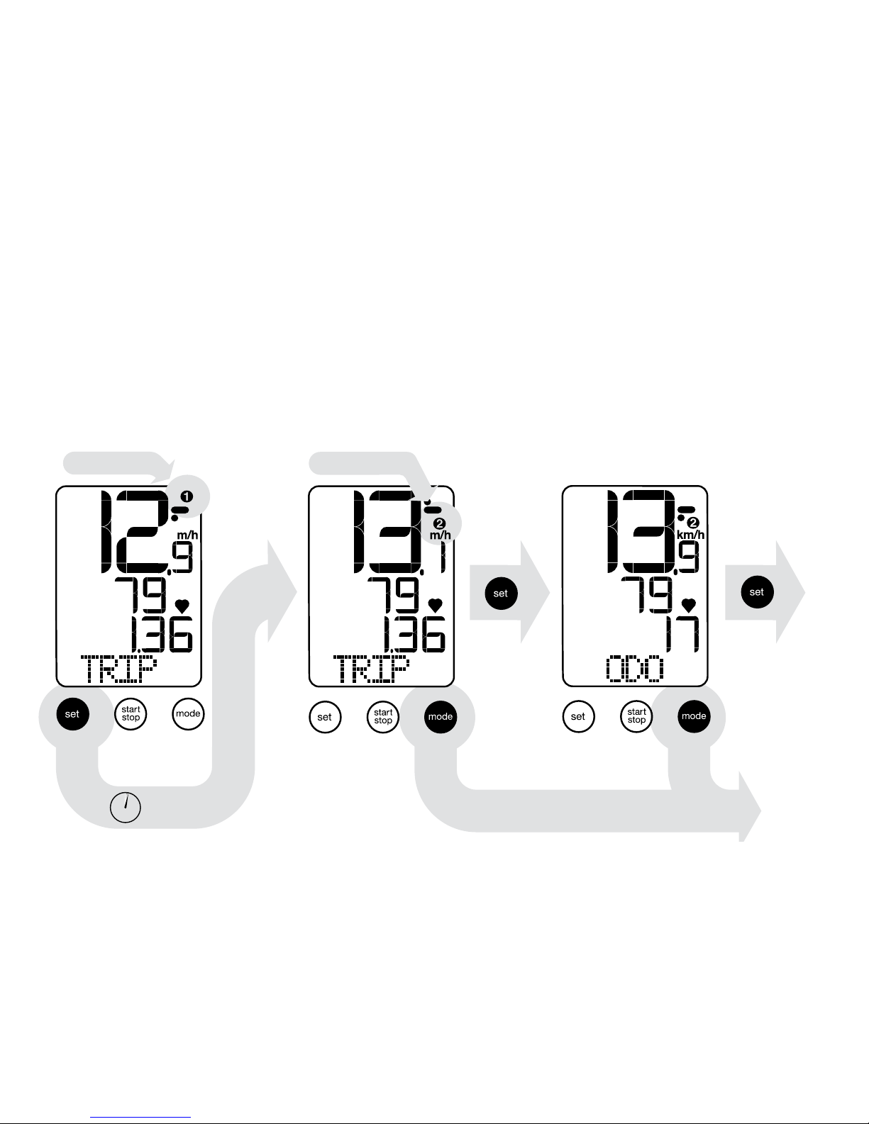
When in “TRIP“ mode, press “set“ key for two seconds.
Devices (ANT+ transmitters) must be “paired” for second (bike
#2) setting.
Selecting Bike #1 - #2 setting
2 sec.
*bicycle #1
proceeds to AVGSPD function
*bicycle #2
Page 20
20
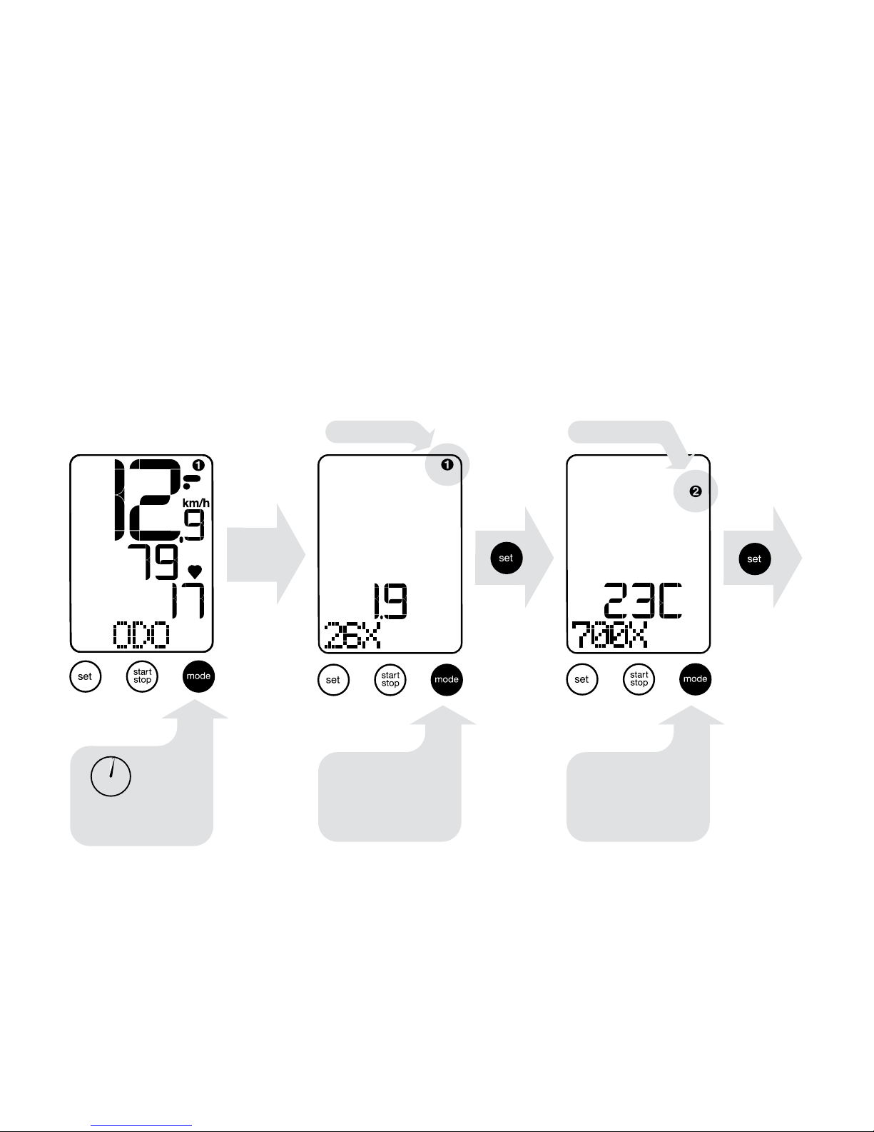
*bicycle #1
*bicycle #2
activates wheel/
tire size options
2 sec
• In “ODO” mode, press “mode” key for two seconds
• Select desired wheel/tire size (see earlier section for details)
Re-setting the wheel/tire size
scroll through
sizes or manually
set size in mm
(see page 10)
scroll through
sizes or manually
set size in mm
(see page 10)
Page 21
21
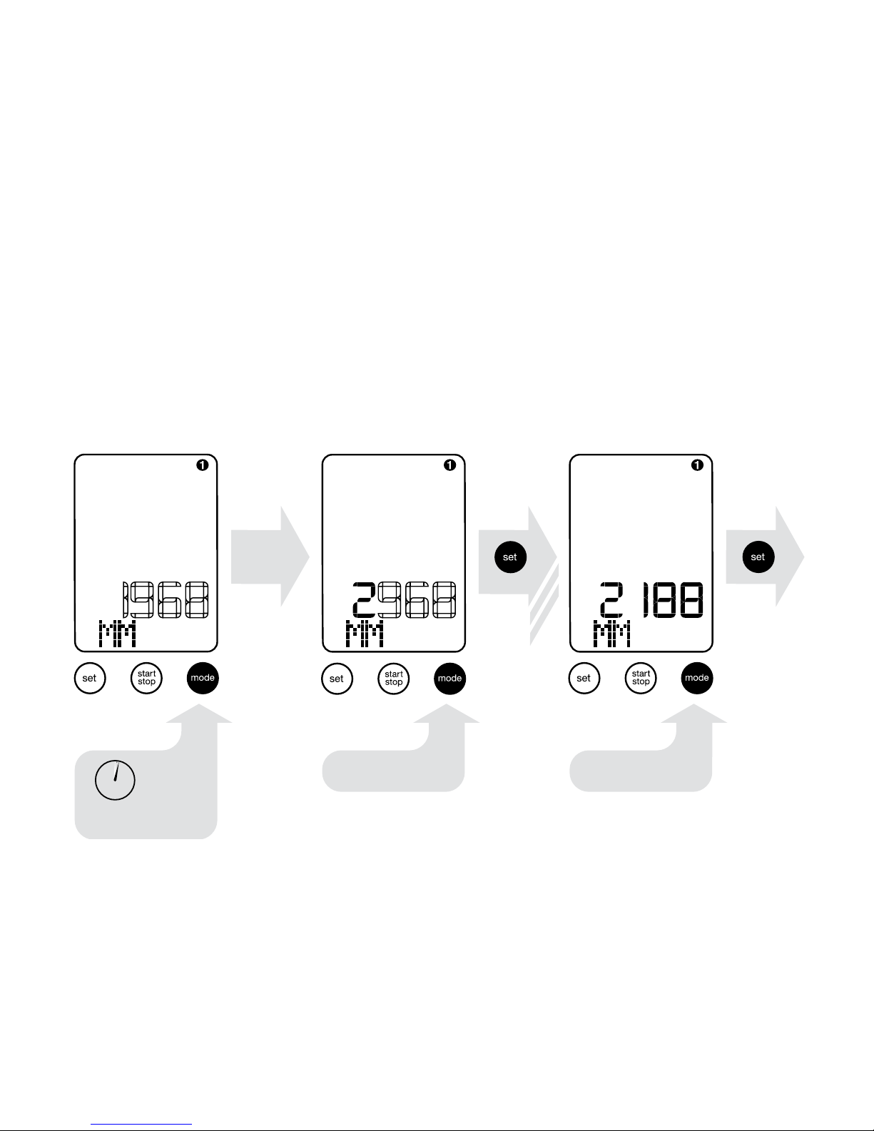
(See wheel circumference calculation page 22)
Manually setting wheel/tire size
select digit select digit
activate 1st digit
2 sec
x3
Page 22
22
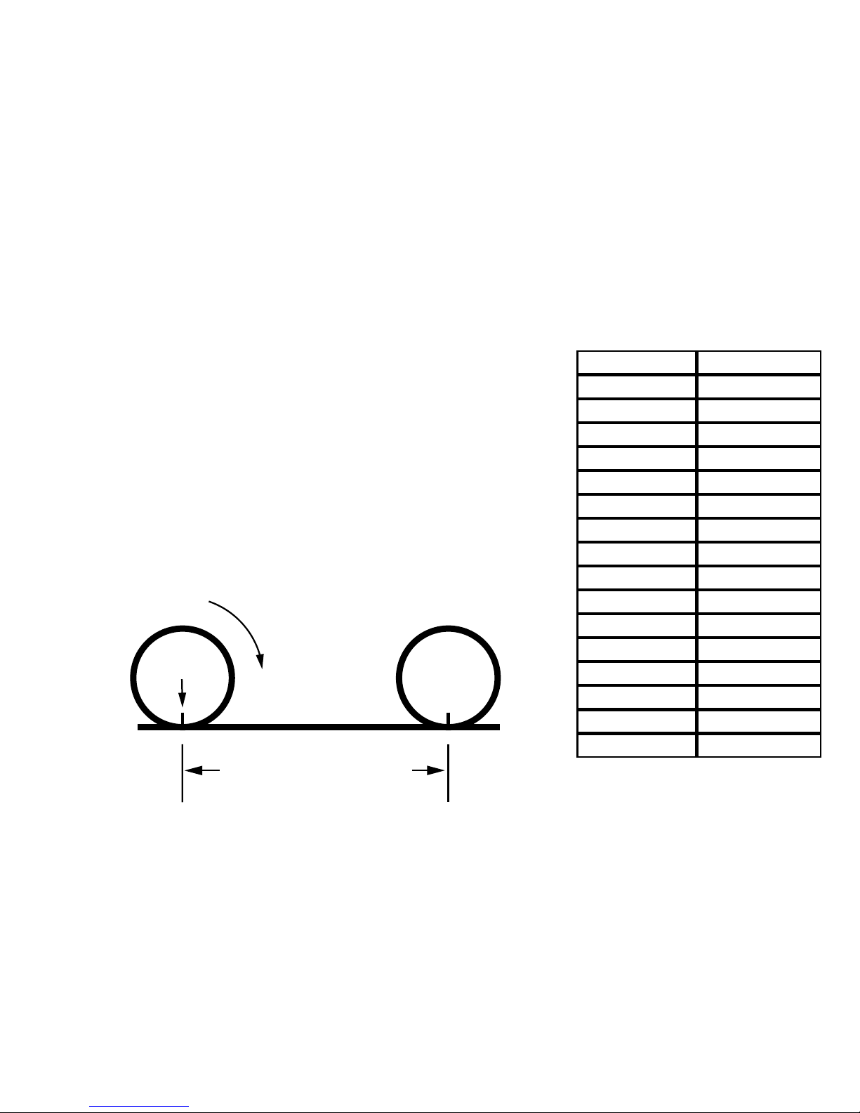
• Mark your tire and the ground where
they meet. Roll bike forward full revolution and mark the point on the oor.
• Measure the distance in millimeters
and enter digits.
Calculating wheel circumference
stem
Wheel circumference
size in MM
Roll forward
one revolution
TIRE SIZE SIZE/MM
26X1.0 1943
26X1.25 1949
26X1.95 2055
26X2.0 2060
26X2.1 2068
26X2.2 2075
29X2.0 2300
650X20C 1945
700X21C 2092
700X23C 2102
700X25C 2113
700X28C 2138
700X32C 2161
700X35C 2175
700X38C 2187
Circumference 0000-2999
Page 23
23
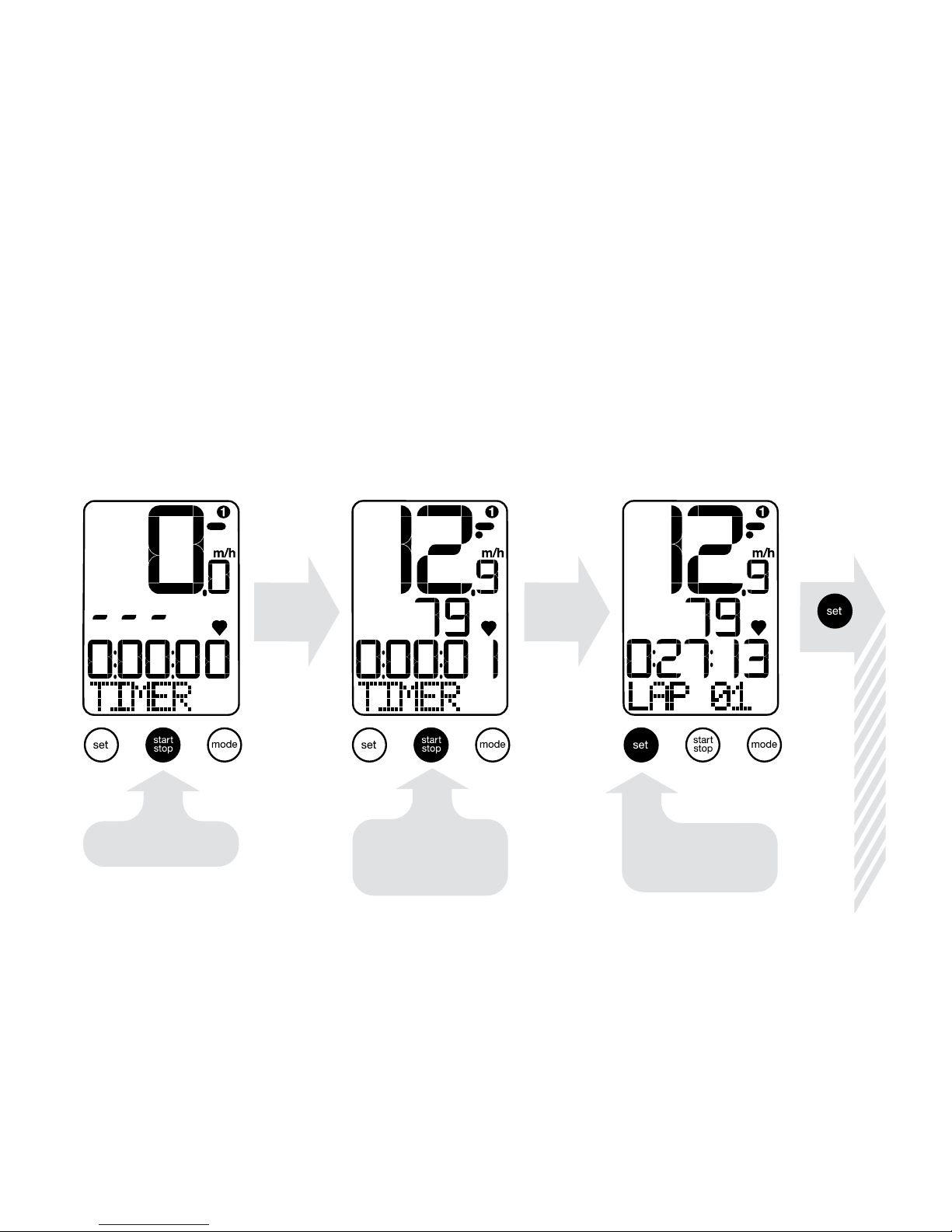
Timer function (Stopwatch/Lap timer). Press “mode” to “ATM”
screen then press “set” to “TIMER” screen.
Using the timer
press to start
Timer continues
until start/stop
is pressed again
Set button starts
Lap function
x12
Page 24
24
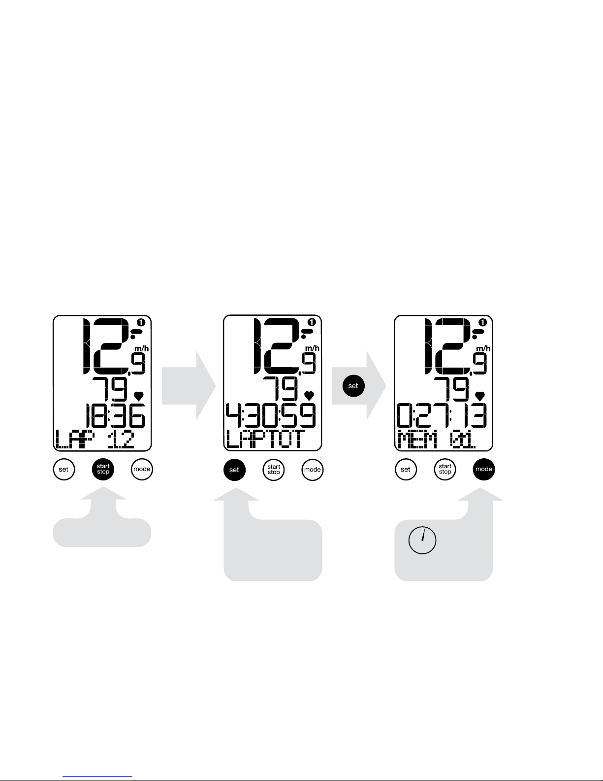
Lap timer function (Stopwatch/Lap timer)
...continued use of timer
press to stop
reset Lap timer
2 sec
Lap time data
can be reviewed
using set key
Page 25
25
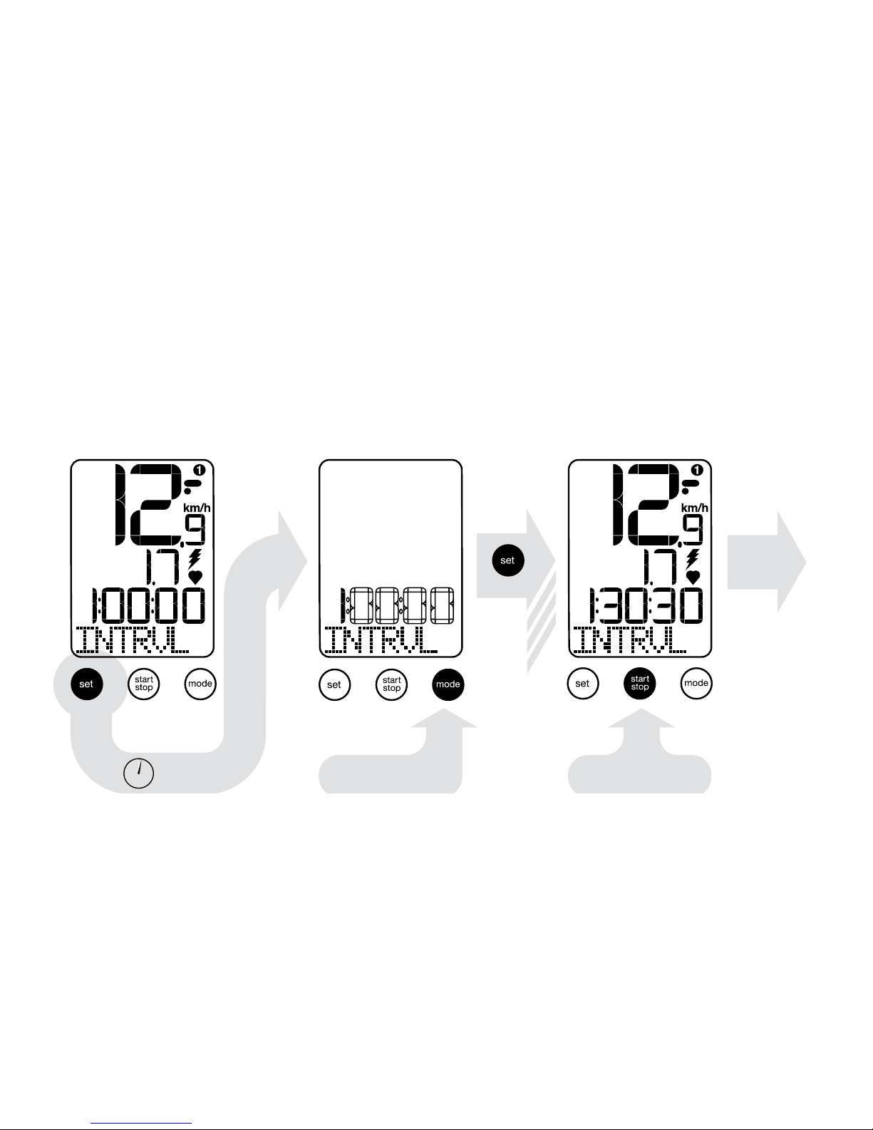
• When in “INTRVL” mode, press “set” key for two seconds.
• Set target interval time using “mode” and “set” keys.
Using the interval timer
select digit
2 sec.
x4
press to start
Page 26
26
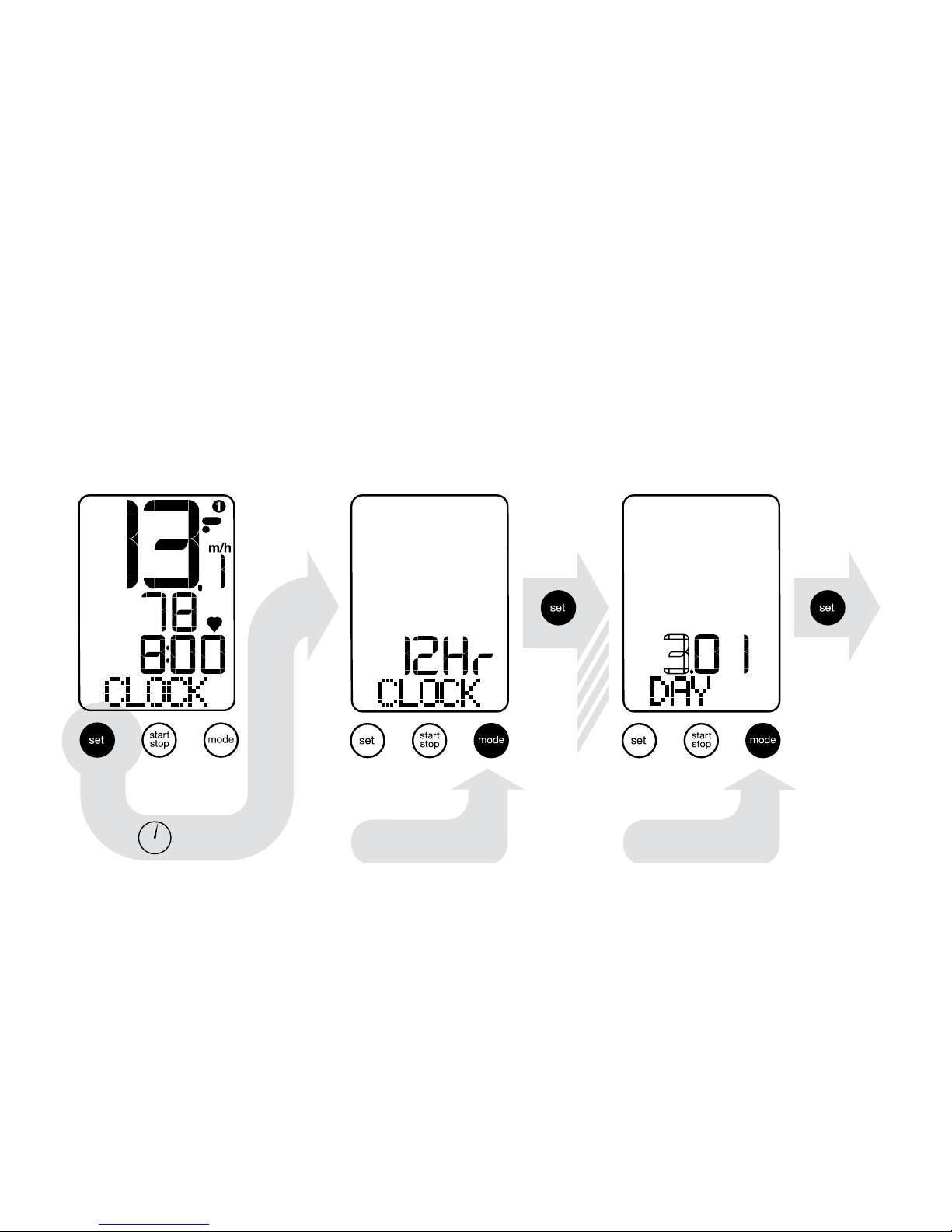
• In “CLOCK” mode, press “set” key for two seconds.
• Set time and date by using “mode” and “set” keys.
• Press “mode” for two seconds to set language.
Re-setting the clock and language
select 12/24 hr
select day
2 sec.
x5
Page 27
27
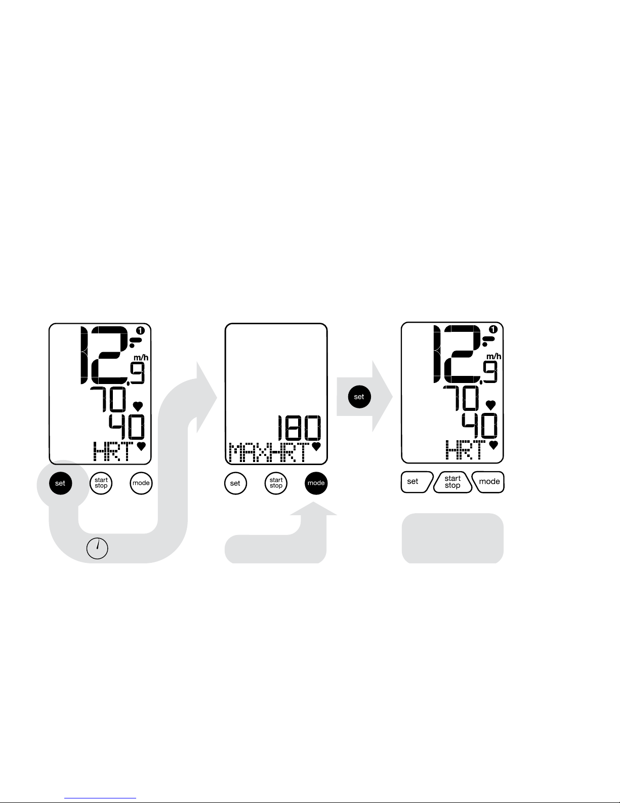
• Max heart rate guideline: 220 minus your age.
• Heart rate zones table on page 32.
Max heart rate setup
2 sec.
enter max HR
return to % of
max heart rate
zone view
Page 28
28
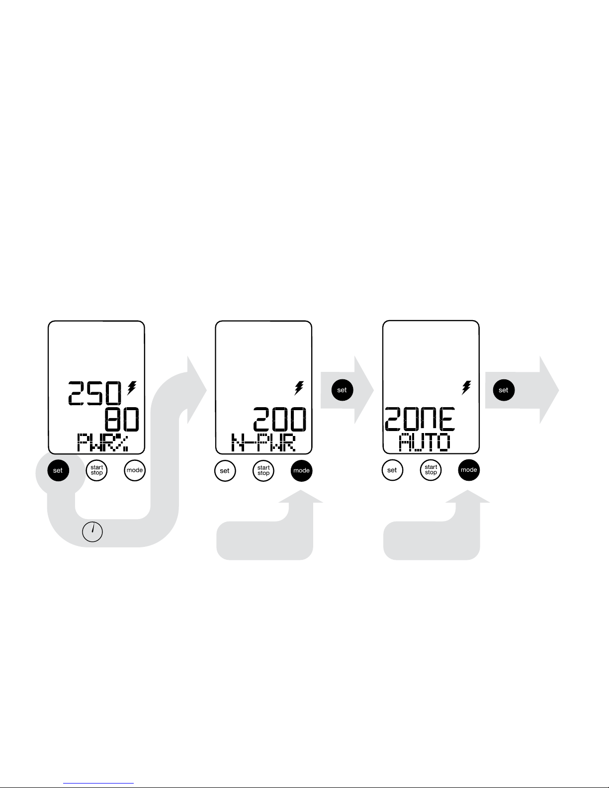
Setting “N-PWR” (normal power) will automatically set 5 (ve)
training zones. Auto power zones table on page 32.
Power function requires ANT+ compatible power devices.
Setting power zones (auto or manual)
enter normal
power
2 sec.
auto
Proceed to
manually set
Page 29
29
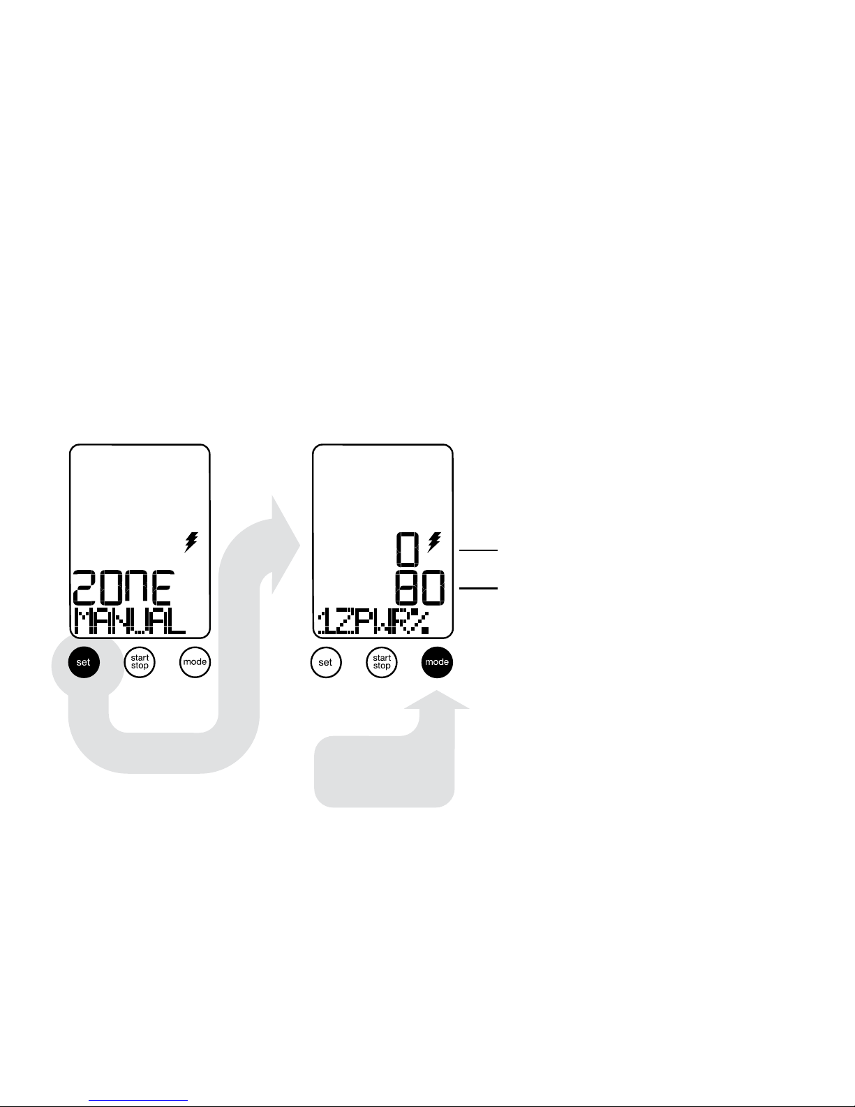
Press “mode” from “ZONE AUTO”
Manual power zone setting
Set upper range
value in % of
normal power
low range (% of N-PWR)
upper range (% of N-PWR)
Page 30
30
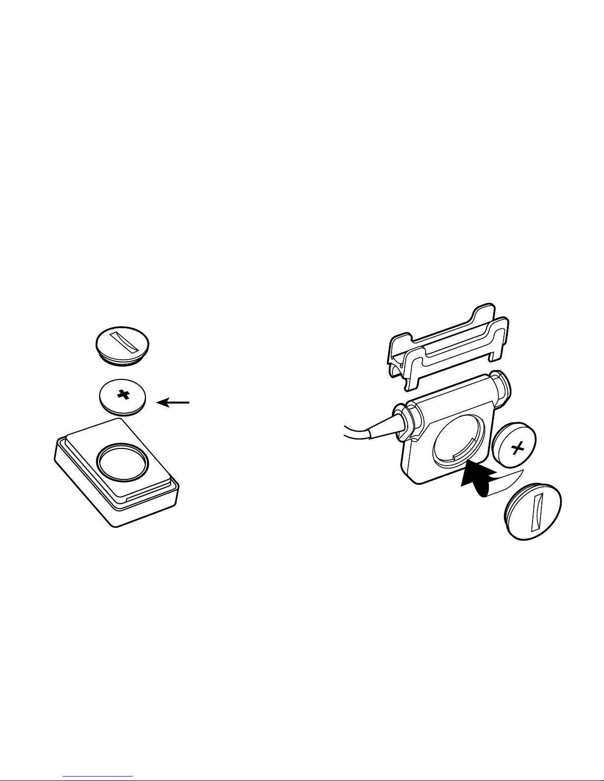
Rotate battery cover quarter turn to remove battery.
Replacing the battery
CR2032 battery
headunit
Speed/cadence sensor
Page 31

31
Specications and ranges
Odometer
• 99999 miles or kilometers
• 1 mile or 1 kilometer resolution
Time of day
• 24 hours with one minute resolution
• Function in either 12 or 24 hour formats
• Default value + 12:00.00 PM January 1,
2012
Wheel size
• 15 pre-programmed wheel sizes
• Wheel circumference measured in millimeters
Speed
• 0-99.9 MPH KPH
• 0.1 MPH or KPH resolution
Cadence
• 30 - 250 RPM with 1 RPM resolution
Stopwatch chronograph
• 9h 59m 59s individual timing session
• 1 second resolution
• 12 lap maximum
Interval countdown timer
• 59m 59s individual timing session
• 1 second resolution
Heart rate
• 30 -240 beats per minute (bpm)
Battery life
• 200 - 300 hours
• Speed/Cadence sensor 400 hours
• Heart rate sensor 400 hours
• Ride duration & frequency may affect total life
Page 32
32
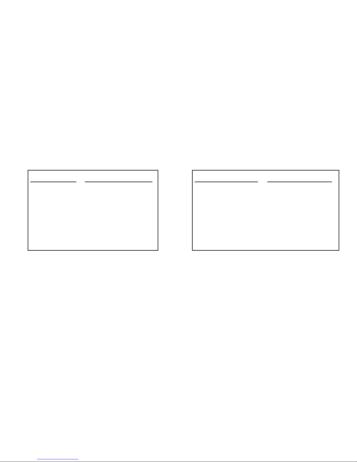
Tables appendix
HR Zone % of Max HR
Zone 1 0% - 60%
Zone 2 61% - 90%
Zone 3 71% - 80%
Zone 4 80% - 90%
Zone 5 91% - 100+%
Power Zone % of N-PWR
Zone 1 0% - 80%
Zone 2 80% - 90%
Zone 3 90% - 100%
Zone 4 100 - 110%
Zone 5 110+ %
Heart rate Zones
“1ZHRT” = Heart rate zone 1
Power Zones
“PWRZN1” = Power Zone 1
Page 33

33
Speedzone Comp Terminology
PC LINK Computer Link
CLOCK Clock
YEAR Year
MONTH Month
DAY Day
DATE Date
TRIP Trip Distance
ODO Odometer
AVGSPD Average Speed
MAXSPD Maximum Speed
ATM Automatic Timer
TIMER Lap Timer
INTRVL Interval Timer
CAD Cadence
AVGCAD Average Cadence
MAXCAD Maximum Cadence
Z HRT Zone # Heart Rate (bpm)
#Z HR% Zone 1 and % of Max HR
AVGHRT Average Heart Rate
MAXHRT Maximum Heart Rate
HRZN1 Heart Rate Zone #(1)
N-PWR Normal(Threshold)Power
PWR% % of Normal Power
AVGPWR Average Power
MAXPWR Maximum Power
ENG KJ Total Energy in Kilo Joules
PWRZN1 Time in Powerzone # (1)
ZONE AUTO Automatic Zone Setting
ZONE MANUAL Manual Zone Setting
Page 34

34
• Display is blank or shows partial digits: Change the battery or reset the computer (page 30).
• Speed/Distance is not recording: Check speed sensor/magnet alignment (page 5). Change battery on speed sensor and computer.
• Heart rate too high: Wet the contact area in the strap.
• Power reading too high: Reset calibration (page 17)
• If power reading still incorrect, contact power device manufacturer with calibration number (see page
14).
• Heart Rate and Power data is not showing: check device for ANT+ compatibility. Check or replace
batteries in transmitters. Check for proper magnet alignment with powermeter device. Re “PAIR”
devices (page 16)
• Computer moves on handlebar: tighten hinge bolt or tie straps. Check rubber spacer between
handlebar and mount.
•
Important:
• Pay attention to trafc and road condition at all times and always obey trafc laws. Your rst obligation is to be attentive and ride safely.
• Never let the operation of the computer distract from riding safely and avoid resetting, troubleshooting
or programming the computer while riding.
• Keep the computer and all of its components tightly attached and check them regularly. If any of the
components come loose, it could become tangled in the spokes or mechanism of the bicycle and
cause an accident.
• Speedzone computer is intended for use on bicycle only and should not be used on motorized
vehicles.
• See your authorized Specialized dealer if you have trouble installing or operating the computer.
Troubleshooting
Page 35

35
Specialized Bicycle Components Inc. (“Specialized”) warrants to the original purchaser that this
product is free of defects in material and workmanship under normal use for period of two (2)
years from the date of original purchase from an authorized Specialized retailer. If this product
is found to be defective in material or workmanship within two (2) years from the date of original
purchase, Specialized will in its sole discretion repair or replace this product without charge,
provided the original purchaser returns the product securely packaged, postage prepaid to:
Specialized Bicycle Components Inc.
1475 S 5070 W, Suite A
Salt Lake City, UT, 84104, USA
Attn: Warranty
The original purchaser must also include a letter indicating the specic reasons for returning this
product and proof of purchase.
This warranty does not apply to and is void as to physical damage resulting from neglect, abuse,
alterations, modications or use contrary to that intended by the manufacturer. Specialized disclaims all implied warranties including those of merchantability and tness for particular purpose.
Under no circumstances shall Specialized be liable for consequential damages.
Full Service and troubleshooting guide and manuals can be found at www.specialized.com
Warranty information
Page 36

36
FCC ID: O4GSPPRO
MADE IN CHINA
This device complies with part 15 of the FCC Rules.
Operation is subject to the following conditions:
this device may not cause harmful interference, and
this device must accept any interference received, including interference that may cause undesired
operation.
NOTES:
THE MANUFACTURER IS NOT RESPONSIBLE FOR ANY RADIO OR TV INTERFERENCE CAUSED
BY UNAUTHORIZED MODIFICATIONS TO THIS EQUIPMENT. SUCH MODIFICATIONS COULD VOID
THE USER AUTHORITY TO OPERATE THE EQUIPMENT.
NOTE: This equipment has been tested and found to comply with the limits for a Class B digital device,
pursuant to Part 15 of the FCC Rules. These limits are designed to provide reasonable protection
against harmful interference in a residential installation. This equipment generates and can radiate radio
frequency energy and, if not installed and used in accordance with the instructions, may cause harmful
interference to radio communications. However, there is no guarantee that interference will not occur in
a particular installation.
If this equipment does cause harmful interference to radio or television reception, which can be deter-
mined by turning the equipment off and on, the user is encouraged to try to correct the interference by
one or more of the following measures:
-- Reorient or relocate the receiving antenna.
-- Increase the separation between the equipment and receiver.
-- Consult the dealer or experienced radio / TV technician for help.
 Loading...