

Page 1

Operating Instructions
2 in 1 brush cutter with grass trimmer spool
34.017.13
Cat-No.: 720-1242 I.-No.: 01016
SPJBC 28
Anleitung SPJBC 28 11.10.2006 17:47 Uhr Seite 1
Page 2

2
Please read these instructions carefully
before installing and operating the
petrol motor scythe!
Petrol Engine Quick Start Guide
Ensure correct fuel/oil mixture 40:1
STARTING
1. Place the trimmer on a hard, level surface.
2. Switch on the ignition (set switch to RUN)
3. Press the fuel primer button ten times
minimum.
4. Set the choke lever to CHOKE.
Note - the amount of Choke will vary slightly
depending on the weather conditions, a
small amount of experimentation is advised.
5. Set the throttle lever to full throttle.
6. Hold the handle firmly when the throttle lever
is locked in place.
7. Pull the starter rope four times.
8. Set the choke lever to START and pull four
times.
9. Set the choke lever to RUN after the motor
has been running for ten seconds.
Note - this quick start guide is intended for
experienced users who have already
assembled the tool, please refer to the
manual for details.
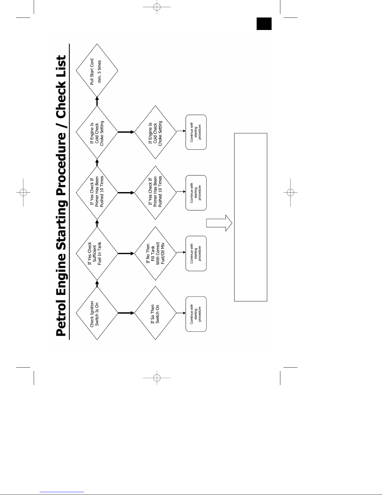
If machine does not start after minimum 6 pulls
on starter cord refer to petrol Engine Q & A on
page 16.
Anleitung SPJBC 28 11.10.2006 17:47 Uhr Seite 2
Page 3
3
A
B C
6
7
8
9
1
2
3
4
6
19
5
7
5
4
20
1
18
3
30
28
11
10
18
26
25
22
24
23
27
29
12
13
16
14
17
15
21
Anleitung SPJBC 28 11.10.2006 17:47 Uhr Seite 3
Page 4
4
D FE
G1 HG2
K L
I1
J2
J1
I2
3
2
5
1
4
2
1
2
3
1
1
2
3
1
4
3
2
5
4
2
1
5
1
2
1
Anleitung SPJBC 28 11.10.2006 17:47 Uhr Seite 4
Page 5
5
A
B
D
E
F
H
H
G
A
A
M5
F
F
H
M1
M2
M3
M4
N1 N2
N3 N4
G
D
G
E
C
N5
C
Anleitung SPJBC 28 11.10.2006 17:47 Uhr Seite 5
Page 6
6
13cm
N8
O
A
P1
C
B
P2
D
P3 Q1
1
2
Q2
H
H
N6 N7
E
F
R
3
4
Anleitung SPJBC 28 11.10.2006 17:47 Uhr Seite 6
Page 7
CAUTION • PLEASE READ
For safety reasons, it is imperative that you read
these operating instructions before using the
appliance. Serious injuries could result if these
instructions are not followed. You must therefore
dedicate a few minutes to studying your new petrol
brush cutter and its instructions before each use.
GENERAL SAFETY REGULATIONS
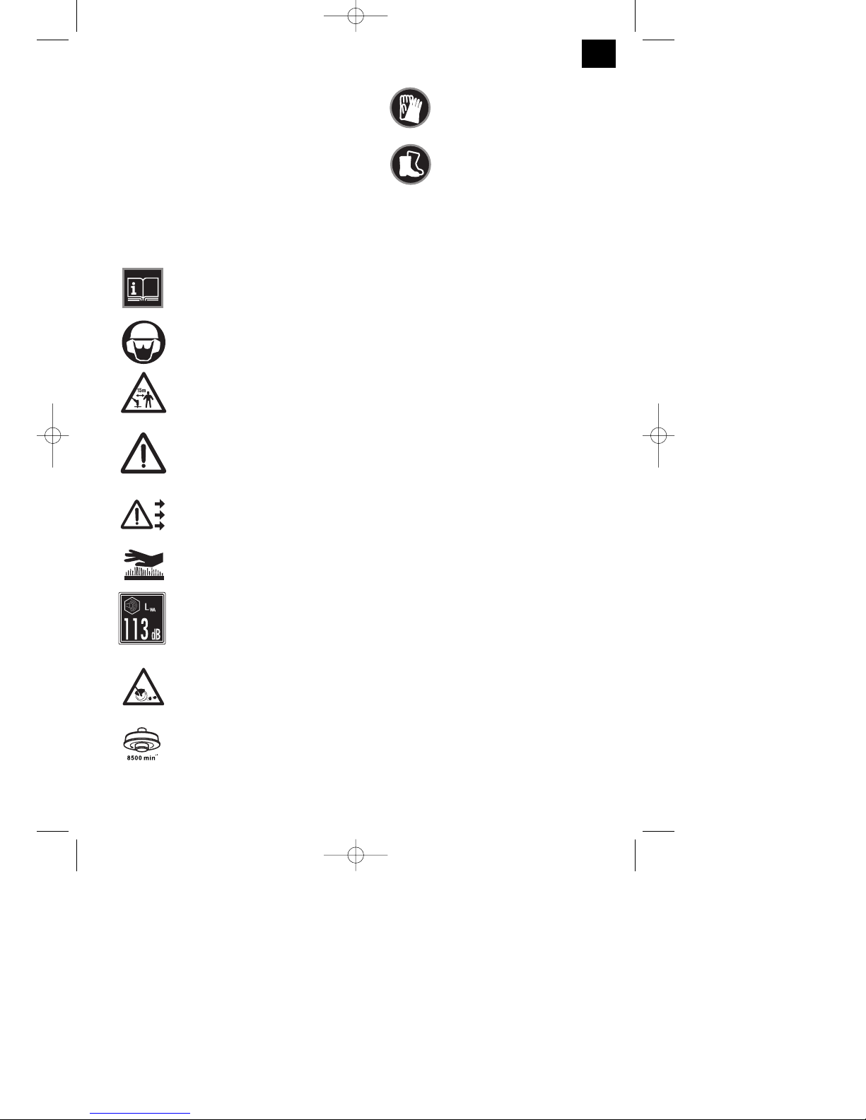
Meaning of the safety symbols used
Read the operating instructions
before you operate the machine.
Wear helmet, ear muffs and goggles!
Keep other people out of the danger
area!
Important! Hazard!
Arrows show the correct handle
position – this must not be changed!
Important! Hot surface!
Guaranteed sound power level
conforming to EU Directive
2000/14/EC
Hazard due to objects being thrown
out!
Maximum speed!
Wear gloves in order to protect
hands.
Wear rubber boots or strong shoes
Safety instructions for hand-operated
petrol brush cutter
Note
1. Read the directions with due care. Familiarize
yourself with the settings and proper operation of
the machine.
2. Never allow children or other persons who are
not familiar with the operating instructions to use
the petrol power brush cutter. Contact your local
governmental agency for information regarding
minimum age requirements for operating the
petrol brush cutter.
3. Never use the machine in direct vicinity of
persons, especially children or animals
Warning:
Maintain a safety distance of 15m. If
approached, switch off the appliance
immediately.
Always keep in mind that the machine operator
or user is responsible for accidents involving
other persons and/or their property.
Preliminary measures
1. Always wear sturdy, non-slip footwear and long
trousers when using the machine. Never use the
machine barefoot or in sandals.
2. Check the grounds on which the machine will be
used and remove all objects that could be caught
up and violently flung out.
3. Warning: Petrol is highly flammable! Therefore:
- Only store petrol in containers designed to hold
petroleum-based liquids.
- Only refuel out in the open and do not smoke
during the refueling process.
- Always refuel before starting the engine. Do not
open fuel tank cap and do not refuel when the
engine is running or when the scythe is hot.
- If petrol has overflowed, do not under any
circumstances attempt to start the engine.
Instead, remove the machine from the affected
area. Avoid starting the engine until the petrol
1
2
3
4
5
6
7
8
9
10
11
GB
7
Helpline No: UK 0151 649 1500 / IRE 189 094 6244
Anleitung SPJBC 28 11.10.2006 17:47 Uhr Seite 7
Page 8

GB
8
Helpline No: UK 0151 649 1500 / IRE 189 094 6244
fumes have completely evaporated.
- For safety reasons, the petrol tank and other
tank closures must be replaced if they are
damaged.
4. Replace defective silencers.
5. Before using the brush cutter, visually inspect it
to ensure that the blade, mounting bolts and the
entire cutting apparatus are in good working
order (i.e. not worn out or damaged). To prevent
any imbalance, replace worn out or damaged
blades and mounting bolts as a set only (if
applicable).
1. Handling
1. Wear close fitting, tough work clothing that
will provide protection, such as long slacks or
trousers, safety work shoes, heavy duty work
gloves, hard hat, a safety face shield, or safety
glasses for eye protection and a good grade of
ear plugs or other sound barriers for hearing
protection.
2. Store in a safe place. Open fuel cap slowly to
release any pressure which may have formed in
fuel tank. To prevent a fire hazard, move at
least 10 feet (3 meters) from fueling area before
starting.
3. Turn unit off before setting it down.
4. Always hold unit firmly with both hands, the
thumb and fingers encircling the handles.
5. Keep all screws and fasteners tight. Never
operate your equipment when it is improperly
adjusted or not completely and securely
assembled.
6. Keep handles dry, clean and free of fuel
mixture.
7. Keep cutting head as close to ground as
practical. Avoid hitting small objects with cutting
head. When cutting on a slope, stand below
cutting head. NEVER cut or trim on a hill or
slope, etc. if there is the slightest chance of
slipping, sliding or losing firm footing.
8. Check area you will be trimming for debris
that may be struck or thrown during operation.
9. Keep all parts of your body and clothing
away from cutting head when starting or
running engine. Before starting engine, make
sure stringhead will not come in contact with any
obstacle.
10. Stop engine before examining cutting line.
11. Store equipment away from possible
flammable materials, such as gas-powered
water heaters, clothes dryers, or oil-fired
furnaces, portable heaters, etc.
12. Always keep the debris shield, cutting head,
and engine free of debris build-up.
13. Operation of equipment should always be
restricted to mature and properly instructed
individuals.
SAFETY WHEN HANDLING THE BLADE
1. FOLLOW ALL WARNINGS and instructions for
using the machine and for installing the blade.
2. The blade may suddenly jump away out of
control if it comes up against objects which it
cannot cut through. This may result in injury
Keep onlookers and animals at least 15 m away
from where you are working. If the machine
strikes a foreign body, stop the engine
immediately and bring the blade to a standstill.
Check the blade for signs of damage. Always
replace the blade if it shows any signs of
damage or it appears to be bent or out of
alignment.
3. THE BLADE WILL THROW UP OBJECTS AT
HIGH SPEED: This may cause eye
injuries. Always wear eye, face and leg
protection. Remove all objects from the working
area before using the blade. Keep other people
and animals at least 15 m away from the
machine in all directions.
4. Check your machine and other equipment
carefully for signs of damage. Do not use the
machine unless all the blade mountings have
been installed correctly.
5. THE BLADE WILL SLOW DOWN AND STOP IF
YOU RELEASE THE THROTTLE VALVE (gas
lever). While it is slowing down, the blade can still
cause injury. Before you carry out any
work on the blade, switch off the engine and
make sure that the blade has stopped.
6. DANGER ZONE WITH A DIAMETER OF 15
METERS. Onlookers may suffer injuries. Keep
onlookers and animals at least 15 m away from
where you are working.
WHAT NOT TO DO
1. DO NOT USE ANY OTHER FUEL than that
recommended in your manual. Always follow
instructions in the Fuel and Lubrication section of
this manual. Never use gasoline unless it is
properly mixed with 2-stroke engine lubricant.
Permanent damage to engine will result, voiding
manufacturer’s warranty.
2. DO NOT SMOKE while refueling or operating
equipment.
3. DO NOT OPERATE UNIT WITHOUT A
Anleitung SPJBC 28 11.10.2006 17:47 Uhr Seite 8
Page 9

GB
9
Helpline No: UK 0151 649 1500 / IRE 189 094 6244
SILENCER and properly installed muffler shield.
4. DO NOT TOUCH or let your hands or body come
in contact with the exhaust. Hold unit with
thumbs and fingers encircling the handles.
5. DO NOT OPERATE UNIT IN AWKWARD
POSITIONS, off balance, outstretched arms, or
one-handed. Always use two hands when
operating unit with thumbs and fingers encircling
the handles.
6. DO NOT RAISE CUTTING HEAD above ground
level while unit is operating. Injury to operator
could result.
7. DO NOT USE UNIT FOR ANY PURPOSES
OTHER than trimming lawn or garden areas.
8. DO NOT OPERATE UNIT FOR PROLONGED
PERIODS. Rest periodically.
9. DO NOT OPERATE UNIT WHILE UNDER THE
INFLUENCE OF ALCOHOL OR DRUGS.
10. DO NOT OPERATE UNIT UNLESS DEBRIS
SHIELD AND/OR GUARD IS INSTALLED AND
IN GOOD CONDITION.
11. DO NOT ADD, REMOVE OR ALTER ANY
COMPONENTS OF THIS PRODUCT. Doing so
could cause personal injury and/or damage the
unit voiding the manufacturer’s warranty.
12. DO NOT operate your unit near or around
flammable liquids or gases whether in or out of
doors. An explosion and/or fire may result.
13. DO NOT USE ANY OTHER CUTTING TOOLS.
For your own safety only use the accessories
and additional equipment specified in the
operating manual or recommended or specified
by the manufacturer. The use of tools or
accessories other than those recommended in
the operating manual or catalog may place you in
danger of personal injury.
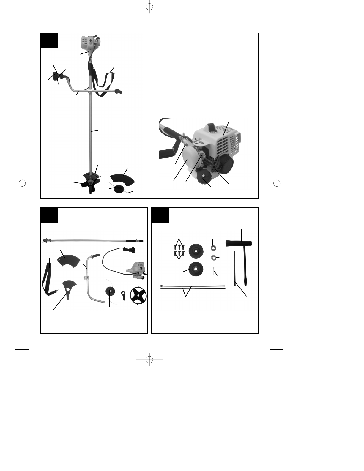
2. Layout and items supplied (Fig. A, B
and C)
A/1, B/1 Cutting head
A/2 Cutting line
A/3, B/3 Outer guard hood
A/4, B/4 Cutting blade
A/5, B/5 Inner guard hood
A/6, B/6 Long handle with drive shaft
A/7, B/7 "Bike” handle
A/8 Throttle lever in the right-hand handle
A/9 Engine switch "off” and "on”
A/10 Throttle lever "lock”
A/11 Throttle lever "release”
A/12 Levers for "Choke" - "Half Choke" - "Full
Choke"
A/13 Housing for engine cooling and starter
A/14 Petrol tank
A/15 Air filter cover
A/16 Handle for cable pull start
A/17 Petrol accumulation button
A/18,B/18 Carrying strap
A/19 Retainer screw for long handle with drive
shaft
B 20 Tool for cutting head and cutting wire
C/21 3 M5 screws for inner guard hood
C/22 3 M6 screws for outer guard hood
C/23 Spacer sleeve
C/24 Carrier plate for cutting head or cutting
blade
C/25 Pressure plate for cutting blade assembly
C/26 Fastening nut for cutting blade
C/27 2xCable tie
C/28 Safety split pin
C/29 Retainer pin for carrier plate
C/30 Key for spark plug and fastening nut
SAFETY DEVICES
It is imperative that the GUARD HOOD is assembled
in order to prevent injuries to the operator due to
objects thrown out by the machine. In addition, the
integrated blade in the guard hood automatically cuts
the cutting line to the optimum length.
TECHNICAL SPECIFICATIONS
Engine type: Air cooled 2-stroke engine,
cylinder hard-chromium plated
Displacement 28 cm
3
Power: 0.75 kW / 1 HP
Dry weight 5.8 kg
Fuel capacity 520 ccm
Guide bar length 147 cm
Cutting width with twin line 43 cm
Line diameter 2.5 mm
Cutting width with cutting blade 23 cm
Cutting blade 4 teeth
Handle “Bike” handle
Ignition Electronic
Spark plug Champion RDJ 8J
Drive Centrifugal clutch
LPA sound pressure level 103 dB(A)
LWA sound power level 113 dB(A)
Vibration 11.41 m/s
2
max. RPM with twin line 8500 min
-1
max. RPM with cutting blade 11,000 min
-1
Idle speed 3050 ± 350 min
-1
Petrol consumption 620 g/kWh
Anleitung SPJBC 28 11.10.2006 17:47 Uhr Seite 9
Page 10

GB
10
Helpline No: UK 0151 649 1500 / IRE 189 094 6244
3. Proper operation
The petrol power brush cutter is intended for private
use, i.e. for use in home and gardening
environments.
The operating instructions as supplied by the
manufacturer must be kept and referred to in order to
ensure that the petrol power brush cutter is properly
used and maintained. The instructions contain
valuable information on operating, maintenance and
servicing conditions.
Important! Due to the high risk of bodily injury to the
user, the petrol brush cutter must not be used to
carry out the following work: to clean dirt and debris
off walkways, or to chop up tree or hedge clippings.
Moreover, the petrol power scythe may not be used
to level out high areas such as molehills.
For safety reasons, the petrol power brush cutter
may not be used as a drive unit for other work tools
or toolkits of any kind.
4. Assembling the components
Some parts of the petrol brush cutter come
disassembled. For quick and easy assembly, read
and follow the instructions below.
Important! You will need the following additional tools
(not supplied) for assembly, and also for
maintenance work:
앬 a screwdriver
앬 an Allen key
앬 a torque wrench size 25
앬 a 1 liter measuring jug (oil / petrol resistant)
앬 a petrol can (5 liter)
앬 a funnel (suitable for the tank’s petrol filler neck)
앬 household wipes (to wipe up oil / petrol residue;
dispose of these at the petrol filling station)
앬 2-stroke oil (available at the petrol filling station)
앬 replacement safety split pins as in Fig. C/28
Assembly Instructions
Assembly of the long handle
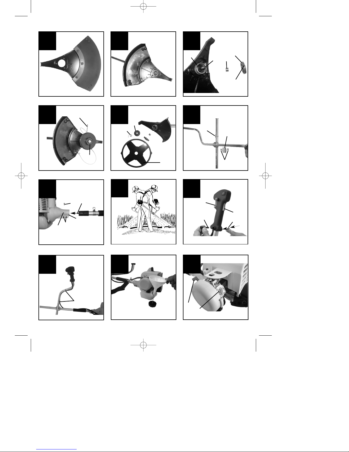
Mount the inner guard hood (Fig. B/5) and the outer
guard hood (Fig. B/3) using the three M6 screws
(Fig. C/22) as shown in Fig. D. Mount the guard
hoods on the long handle (Fig. B/6) using the three
M5 screws (Fig. C/21), as shown in Fig. E.
Push the distance spacer (Fig. F/1) onto the locating
pin of the drive shaft (Fig. F/3). Push the carrier plate
(Fig. F/2) onto the locating pin and, in doing so,
make sure that the cut-out (Fig. F/4) on the carrier
plate coincides with the cut-out on the long handle
(Fig. F/5).
Important: You can align the two cut-outs by turning
the carrier plate.
Important: You must now decide which type of work
you want to undertake with the petrol brush cutter
first (cutting with the cutting head or using the cutting
blade), and then carry out the appropriate assembly
work.
Assembly of the cutting head
Now put the retainer pin (Fig. G1/2) into the cut-out
hole and screw the cutting head (Fig. G1/1) onto the
locating pin of the drive shaft by turning it in counterclockwise direction (Important: Left-hand screw-
thread!).
Tighten the cutting head by hand, holding the drive
shaft in place with the retainer pin.
Assembly of the cutting blade
Place the cutting blade (Fig. G2/1) on the carrier
plate in such a way that the center of the cutting
blade is situated precisely on the guide circle on the
carrier plate.
Place the pressure plate (Fig. G2/2) on the cutting
blade ensuring that the flat side points to the cutting
blade.
Tightly screw the fastening nuts (Fig. G2/3) on the
locating pin by turning them in counter-clockwise
direction (Important: Left-hand screw-thread!)
Place the retainer pin, as described in the assembly
of the cutting head, in the appropriate cut-out hole
and use the key (Fig. C/30).
Assembly of the "bike" handle
Unscrew both of the lower screws (Fig. H/1) on the
pre-assembled "bike" handle and place them on the
long handle, as shown in Fig. H, between the
fastening hooks for the retaining belt (Fig. H/3) and
the safety label. Now secure the clamping plate (Fig.
H/2) to the "bike" handle using the lower screws and
tightly screw these to the long handle.
Important: Final alignment is best carried out after
assembling the drive motor.
Assembling the assembled long handle with the
drive motor
Unscrew the connecting screws (Fig. I1/1 + I1/2)
from the handle of the drive motor. Position the long
handle in relation to the handle of the drive motor as
shown in Fig. I1. Now push the long handle into the
handle in such a way that the alignment opening
(Fig. I1/3) and the rectangular side of the drive shaft
(Fig. I1/4) engage in the appropriate mountings in the
interior of the handle.
Note: This procedure is made easier by turning
slightly to the right and left. The threaded hole of the
long handle must be situated directly underneath the
hole (Fig. I1/5), so that the connecting screw can be
tightened. Tighten the two fixing screws for the long
Anleitung SPJBC 28 11.10.2006 17:47 Uhr Seite 10
Page 11

GB
11
Helpline No: UK 0151 649 1500 / IRE 189 094 6244
handle (Fig. I1/1) again.
Assembly of the engine control handle
Unscrew the screw (Fig. J1/1) from the handle. Using
sufficient force, push the handle onto the free end of
the "bike" handle in such a way that the throttle
control operating lever (Fig. J1/4) points to the guard
hoods on the long handle. Turn the handle until the
hole for the screw coincides with the hole on the
"bike" handle.
Secure the handle to the "bike" handle using the
screw and the nut (Fig. J1/2). Secure the control
cable of the handle using the cable ties (Fig. C27) so
that the position illustrated (Fig. J2/1) is achieved.
Important: Do not tighten the cable ties fully at
this point. After the engine has been started for
the first time, push the throttle handle through
(Fig. J1/4) and then loose your hold on it. If you
now push the throttle handle again, it is blocked
by the safety lever (Fig. J1/5). When pressing the
throttle control, the speed of the engine must not
rise to the point of the safety stop.
Up to this point, the engine must only be in idle
mode. Check the position of the cable ties for the
purposes of this function before tightening them
fully.
5. Setting the cutting height
Shoulder strap:
1. Slip the shoulder strap (Fig. A/18) over the left
shoulder.
2. Hook the locking hook into eye B (Fig. H/3).
3. Set the length of the shoulder strap in such a
way that the cutting head or the cutting blade
runs parallel to the ground. In order to establish
the optimum length of the shoulder strap, you
should then make a few swinging movements
without starting the engine (Fig. I2).
Warning: Always use the shoulder strap when using
the appliance. Attach the strap as soon as you have
started the engine and the engine is running in idle
mode. Switch off the engine before you take off the
shoulder strap.
Important: Remove the shoulder strap from the
appliance before you start the engine.
6. Starting up
Fuel and oil:
Start the machine at least 3 m away from the
refueling site to avoid the possible risk of fire.
Do not smoke whilst refueling or working with the
machine.
Do not use the hedge trimmer near inflammable
liquids or gases. This could result in an explosion
and/or fire.
1. The engine of the petrol brush cutter is a
2-stroke engine. For operation, it requires a
mixture of normal unleaded petrol and 2-stroke
oil in a ratio of 40:1 (see fuel mixture table).
2. It is advisable to mix a maximum of 5 liters of
petrol/oil mixture, since this quantity will give you
approx. 12-15 operational hours and an older
petrol/oil mixture does not guarantee the
optimum level of lubrication.
3. Pour 125ccm of oil into a measuring jug and then
pour this oil into the 5 liter petrol can. Then
re-close the petrol can. Shake the petrol can
in order to mix the petrol and the oil.
4. Pour approx. 0,5 liters of the petrol/oil mixture
into the measuring jug and then pour this into the
petrol tank using a suitable funnel (Fig. K).
Warning: Never use pure petrol for your appliance.
Otherwise there is a danger of causing permanent
damage to the engine and as a result the
manufacturer's guarantee would not apply. Do not
use any petrol/oil mixture which has been kept for
longer than 90 days.
Warning: Only use a petrol/oil mixture in a mixing
ratio of 40:1. Do not change the mixing ratio of your
own accord even if some types of 2-stroke oil
recommend a different mixing ratio. If insufficient
lubrication causes damage to the engine, the
manufacturer’s guarantee does not apply.
Fuel mixture table:
Petrol (unleaded) 2-stroke oil
5 liters 125 ccm
40 to 1
앬 Starting the engine:
Important: You must first read the instructions for
starting the engine from a cold and a warm state,
and then carry out the appropriate start procedure.
Place the appliance on a hard, level surface, hold it
by the handle with one hand and pull the starting
handle on the tension cable with the other hand.
Important: In order to keep the load on the engine as
small as possible during start-up and warm-up, cut
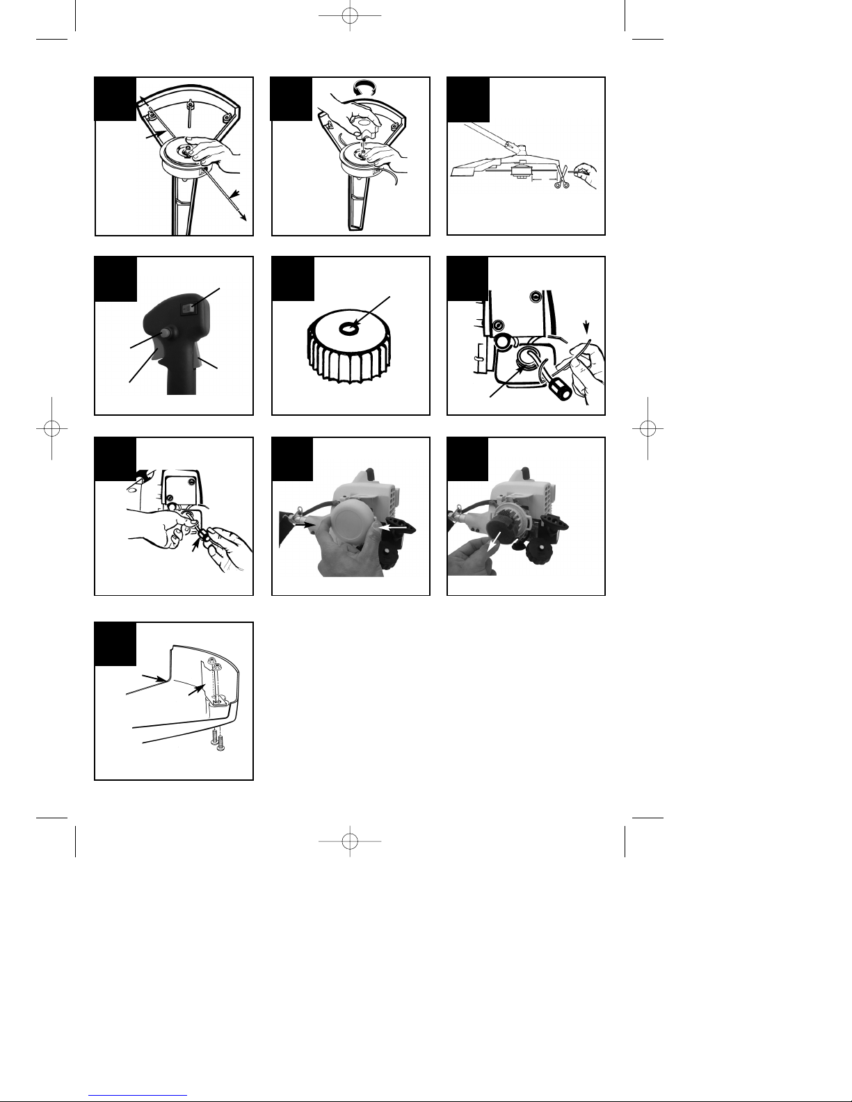
the excess cutting line back to 13cm (Fig. N8).
앬 STARTING THE ENGINE FROM A COLD
STATE
1. Set the ignition switch to the "RUN (l)" position
(Fig. O/1).
2. Secure the throttle lever: Press the “Lock off”
Anleitung SPJBC 28 11.10.2006 17:47 Uhr Seite 11
Page 12

GB
12
Helpline No: UK 0151 649 1500 / IRE 189 094 6244
switch (Fig. O/3) downward. Then, at the same
time, press the throttle lever (Fig. O/4) and the
locking switch (Fig. O/2) at the same time. The
throttle lever locks into place on full throttle.
3. The appliance has a choke, which can been set
in 3 positions: "CHOKE" , "START" and
"RUN " . Set the choke lever to "CHOKE"
(Fig. L/1).
4. For starting purposes, spray fuel into the
carburetor. Press the fuel primer button ten times
minimum(Fig. L/2).
5. Pull the starting cable out by a short amount,
until you feel resistance (approx. 10cm). For a
strong ignition spark, a smooth, sharp pull is
required. Pull the starting cable four times quickly
and forcefully.
6. Set the choke lever to "START".
7. Pull the starting cable four times again, whilst the
throttle lever is set to full throttle.
8. If the engine starts, leave the lever on "START"
for 10 seconds.
9. Set the choke lever to "RUN ".
10. If the engine does not start up, repeat steps 1 to
9.
PLEASE NOTE: If the engine does not start up even
after several attempts, read the section "Engine
Troubleshooting”.
PLEASE NOTE: Always pull the starting cable out in
a straight line. If it is pulled out at an angle, then
friction will occur on the eye. As a result of this
friction, the cable will become frayed and will wear
away faster. Always hold the starter handle when the
cable retracts. Never allow the cable to snap back
when it has been pulled out. This would fray or wear
the cable and also damage the starter unit.
앬 STARTING THE ENGINE FROM A WARM
STATE
1. Set the ignition switch to the "RUN (l)” position
(Fig. O/1).
2. Set the choke lever to the "START" position.
3. Lock the throttle lever as described under Point 2
of "Starting the engine from a cold state”.
4. Pull the starter cable quickly, until the engine
starts up. However, do not pull the cable more
than 6 times. Hold down the throttle lever
FULLY, until the engine is running quietly.
5. If the engine does not want to start, set the
choke to "RUN " and pull 5 more times on the
starter cable. However, should the engine not
start, then it is probably fully-pumped with petrol.
Wait 5 minutes and then try it again with the
choke set to "RUN " and with a fully depressed
throttle lever.
앬 TO STOP ENGINE
Release throttle trigger. Let engine return to idle.
Push and hold ignition stop switch until engine stops
(Fig. O/1).
Trimming Instructions
앬 ADDITIONAL SAFETY PRECAUTIONS
Before operating your unit, review ALL SAFETY
PRECAUTIONS in this manual.
WARNING / CAUTION
1. IF UNFAMILIAR WITH TRIMMING techniques,
practice the procedures with ENGINE in “OFF”
position.
2. ALWAYS CLEAR WORK area of debris such as
cans, bottles, rocks, etc. Striking objects can cause
serious injury to operator or bystanders and also
damage equipment. If an object is accidentally hit,
immediately TURN ENGINE OFF and examine
equipment. Never operate unit with damaged or
defective equipment.
3. ALWAYS TRIM OR CUT AT HIGH ENGINE
SPEEDS. Do not run engine slowly at start or
during trimming operations.
4. DO NOT use equipment for purposes other than
trimming or mowing weeds.
5. NEVER raise cutting head above knee height
during operation.
6. DO NOT operate unit with other people or animals
in the immediate vicinity. Allow a minimum of 50
feet (15 meters) between operator and other
people and animals when trimming or mowing.
Allow a distance of 100 feet (30 meters) between
operator and other people and animals when
SCALPING with cutting head cutter.
7. IF OPERATING UNIT ON A SLOPE, stand below
the cutting attachment. DO NOT OPERATE on a
slope or hilly incline if there is the slightest chance
of slipping or losing your footing.
앬 STRINGHEAD LINE RELEASE
WARNING: DO NOT use steel wire or plastic-
coated steel wire of any kind with your cutting head.
Serious operator injury can result.
To release fresh line, run engine at full throttle and
“bump” cutting head against lawn. Line will
automatically release. The knife in debris shield will
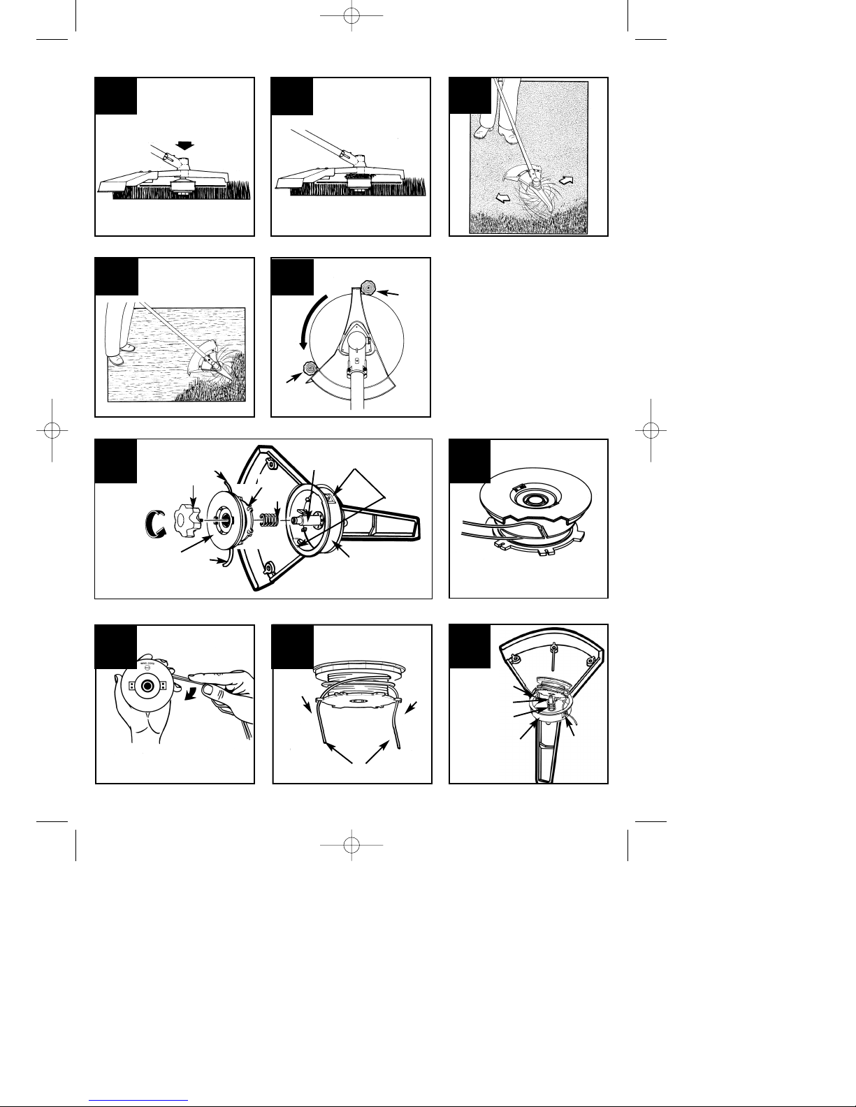
trim excess line (Fig. M1).
Anleitung SPJBC 28 11.10.2006 17:47 Uhr Seite 12
Page 13

GB
13
Helpline No: UK 0151 649 1500 / IRE 189 094 6244
CAUTION: Periodically remove weed wrap to
prevent overheating the drive shaft. Weed wrap
occurs when strands of weed become entangled
around the shaft beneath the debris shield (Fig. M2).
This condition prevents the shaft from being properly
cooled. Remove weed wrap with screwdriver or
similar
device.
앬 TRIMMING PROCEDURES
When properly equipped with a debris shield and
cutting head, your unit will trim unsightly weeds and
tall grass in those hard-to-reach areas - along
fences, walls, foundations and around trees. It can
also be used for scalping to remove vegetation down
to the ground for easier preparation of a garden or to
clean out a particular area.
NOTE: Even with care, trimming around foundations,
brick or stone walls, curves, etc., will result in above
normal string wear.
TRIMMING / MOWING
Swing trimmer with a sickle-like motion from side to
side. Do not tilt the cutting head during the
procedure. Test area to be trimmed for proper cutting
height. Keep cutting head at same level for even
depth of cut (Fig. M3).
CLOSER TRIMMING
Position trimmer straight ahead with a slight tilt so
bottom of cutting head is above ground level and
string contact occurs at proper cutting point. Always
cut away from operator. Do not pull trimmer in toward
operator.
FENCE / FOUNDATION TRIMMING
Approach trimming around chain link fences, picket
fences, rock walls and foundations slowly to cut
close without whipping spool line against the barrier.
If the spool line comes in contact with rock, brick
walls, or foundations, it will break or fray. If string
snags fencing, it will snap off.
TRIMMING AROUND TREES
Trim around tree trunks with a slow approach so
string does not contact bark. Walk around the tree
trimming from left to right. Approach grass or weeds
with the tip of the string and tilt cutting head slightly
forward.
WARNING: Use extreme caution when
SCALPING. Keep a distance of 100 feet (30 meters)
between operator, other people and animals during
these operations.
SCALPING
Scalping refers to removal of all vegetation down to
the ground. To do this, tilt the stringhead to about a
30 degree angle to the left. By adjusting the handle
you will have better control during this operation. Do
not attempt this procedure if there is any chance
flying debris could injure operator, other people or
cause damage to property. (Fig. M4)
Cutting with blades
WARNING: Before you use this machine with a
blade, check that it has been fitted correctly. Follow
all the instructions set out in the section entitled
“Safety instructions for undergrowth/grass cutting
blades” in this operating manual.
CUTTING WITH BLADES
Whenever you are cutting with a blade you must
wear eye protection and protective clothing. Always
use the shoulder strap when working with the blade.
WORKING WITH WEED-CUTTING BLADES
MOWING WEEDS
Mowing means moving the blade in a horizontal
curve from one side to the other. This is very
effective for grass-like weeds and small undergrowth.
It is not suitable for cutting large, tough weeds or
woody vegetation (Fig. I2).
CAUTION: Do not use weed-cutting blades for
cutting scrub or young trees.
SAWING
The SPJBC 28 is not designed for sawing.
JAMMING
Very thick vegetation, such as young trees or thick
scrub may jam the blade and bring it to a standstill.
Prevent the blade from jamming by anticipating the
direction in which the scrub leans and cut it from the
opposite side.
If the blade jams while cutting, switch off the engine
immediately. Hold the machine level so that the
blade does not jump or break while you push the
young tree away from the cut to free the blade.
TO PREVENT RECOIL
When using metal cutting tools (grass blades, thicket
knives) there is a risk that the machine will recoil if
the tool strikes a solid object (tree truck, branch, tree
stump, stone or the like). In this case the machine
will jump backwards in the opposite direction to
which the tool is rotating. This may lead to a loss of
control of the tool and risk of injury to the user and
onlookers.
Anleitung SPJBC 28 11.10.2006 17:47 Uhr Seite 13
Page 14

GB
14
Helpline No: UK 0151 649 1500 / IRE 189 094 6244
Do not use metal cutting tools near fences, metal
posts, boundary stones or foundations.
The safety blade is designed to reduce recoil if the
blade strikes a hard, solid object. To cut thick stalks,
place it in position (A), see Fig. M5, to prevent recoil.
Maintenance (Fig N1)
A. KNOB
B. SPOOL
C. SPRING
D. SPINDLE
E. HOUSING
F. SLOTS
G. EYELETS
H. CUTTER LINE
앬 REPLACING CUTTER LINE
1.Turn knob (A) COUNTERCLOCKWISE and
remove (Fig. N1). User knob spanner supplied.
2. Remove spool (B) and spring (C) from spindle (D).
3. Remove any remaining cutter line (H).
4. Double a 14' (4.3m) length of .080" (2mm) cutter
line. Place the looped center in one of the slots of
the spool divider (Fig. N2).
5. Wind cutter line clockwise as shown in illustration
(Fig. N3), keeping tension, with each half
separated by the spool divider. Wind to within 6"
(15cm) of the ends.
6. Lock each end of line into a slot (F) on
opposite sides of the spool (Fig. N4).
7. Install the spring (C) over the spindle (D). Insert
each end of the line through an eyelet (G) in the
housing (E) (Fig. N5).
8. Lower the spool into the housing (E) while
feeding the line through the eyelets (G). Ensure
the spring seats itself into the spool (Fig. N5).
9. Once the spool is in place, apply pressure on the
spool compressing the spring. Pull each end of
the line (H) sharply to unlock the line from the
slots (Fig. N6).
10. Continue to apply pressure to the spool until the
knob can be threaded CLOCKWISE onto the
spindle. Tighten the knob securely by hand only
(Fig. N7).
11. Trim the excess line to approximately 5" (13cm).
This will minimize load on engine during starting
and warm-up (Fig. N8).
앬 AIR FILTER
Caution: Never work without an air filter. Make
sure it is always clean. If it is damaged then it must
be replaced with a new filter.
Empty the petrol tank and pour the fuel into a
suitable jerry can. Open the petrol tank slowly so that
any potential pressure can be released.
Cleaning the air filter: (Fig. Q1/Q2)
1. Remove the air filter cover (Fig. Q1) by
pushing it together sideways a little and
remove the filter element (Fig. Q2).
2. Wash the filter in soapy water. DO NOT USE
ANY PETROL!
3. Air-dry the filter.
4. Refit the filter and attach the air filter cover
again.
PLEASE NOTE: Replace the filter if it is worn
away, torn or damaged, or if it can no longer
be cleaned.
앬 FUEL CAP / FUEL FILTER
Caution: Remove fuel from unit and store in
approved container before starting this procedure.
Open fuel cap slowly to release any pressure which
may have formed in fuel tank.
NOTE: Keep vent (A) on fuel cap clean of debris
(Fig.P1/A).
1. Lift fuel line and filter (B) out of tank. A steel wire
(C) with a hook or a paper clip works well (Fig.
P2).
2. Pull off with a twisting motion (Fig. P3).
3. Check the petrol filter for damage and clean it by
blowing it out with air. Replace the petrol filter
(Fig. P3/D) if it is damaged.
NOTE: Never operate the trimmer without the fuel
filter. Internal engine damage could result!
앬 CARBURETOR ADJUSTMENT
The carburetor was pre-set at the factory for
optimum performance. If further adjustments are
necessary, please take your unit to the nearest
Authorized Service Center.
앬 SPARK PLUG
1. Spark plug gap = .025" (.635mm).
2. Torque to 105 to 130 inch pounds (12 to 15 N•m).
Connect spark plug boot.
앬 DEBRIS SHIELD BLADE SHARPENING
Anleitung SPJBC 28 11.10.2006 17:47 Uhr Seite 14
Page 15

GB
15
Helpline No: UK 0151 649 1500 / IRE 189 094 6244
1. Remove cutter knife (E) from debris shield (F)
(Fig. R).
2. Place knife in a bench vise. Sharpen knife using a
flat file, being careful to maintain the angle of
cutting edge. File in one direction only.
앬 STORING A UNIT
Warning: Failure to follow these steps may
cause varnish to form in the carburetor and difficult
starting or permanent damage following storage.
1. Perform all the general maintenance
recommended in the Maintenance Section of
your User Manual.
2. Clean exterior of engine, drive shaft assembly,
debris shield and stringhead.
3. Drain fuel from the fuel tank.
4. After fuel is drained, start engine.
5. Run engine at idle until unit stops. This will purge
the carburetor of fuel.
6. Allow engine to cool (approx. 5 minutes).
7. Using a spark plug wrench, remove the spark
plug.
8. Pour 1 teaspoon of clean 2-cycle oil into the
combustion chamber. Pull starter rope slowly
several times to coat internal components.
Replace spark plug.
9. Store unit in a cool, dry place away from any
source of ignition such as an oil burner, water
heater, etc.
10. Do not transport and store the trimmer with the
blade fitted unless the supplied transport guard is
also fitted.
앬 REMOVING A UNIT FROM STORAGE
1. Remove spark plug.
2. Pull starter rope briskly to clear excess oil from
combustion chamber.
3. Clean and gap spark plug or install a new spark
plug with proper gap.
4. Prepare unit for operation.
5. Fill fuel tank with proper fuel / oil mixture. See
Fuel and Lubrication Section.
앬 Ordering replacement parts
Please quote the following data when ordering
replacement parts:
Type of machine
Article number of the machine
Identification number of the machine
Replacement part number of the part required
Helpline Numbers:
UK: 0151 649 1500
IRE: 189 094 6244
Anleitung SPJBC 28 11.10.2006 17:47 Uhr Seite 15
Page 16

GB
16
Helpline No: UK 0151 649 1500 / IRE 189 094 6244
Trouble shooting the engine
PROBABLE CAUSE
Incorrect starting procedures.
Incorrect carburetor mixture
adjustment setting.
Fouled spark plug
Fuel filter plugged.
Incorrect lever position on
choke.
Dirty air filter.
Incorrect carburetor mixture
adjustment setting.
Incorrect carburetor mixture
adjustment setting.
Incorrectly gapped spark plug.
Incorrect carburetor mixture
adjustment setting.
Incorrect fuel mixture.
CORRECTIVE ACTION
Follow instructions in the User
Manual.
Have carburetor adjusted by an
Authorized Service Center.
Clean / gap or replace plug.
Replace fuel filter.
Move to RUN position.
Remove, clean and reinstall filter.
Have carburetor adjusted by an
Authorized Service Center.
Have carburetor adjusted by an
Authorized Service Center.
Clean / gap or replace plug.
Have carburetor adjusted by an
Authorized Service Center.
Use properly mixed fuel (40:1
mixture).
PROBLEM
Unit won’t start or starts but will
not run.
Unit starts, but engine has low
power.
Engine hesitates.
No power under load.
Runs erratically.
Smokes excessively.
(after approx. 1 min. in full
throttle position)
Anleitung SPJBC 28 11.10.2006 17:47 Uhr Seite 16
Page 17
17
Helpline No: UK 0151 649 1500 / IRE 189 094 6244
GB
If after trying all of the above procedures please
call the help line for further assistance
Anleitung SPJBC 28 11.10.2006 17:47 Uhr Seite 17
Page 18
18
Helpline No: UK 0151 649 1500 / IRE 189 094 6244
Landau/Isar, den 06.09.2006
Wimmer
Product-Management
Weichselgartner
General-Manager
Art.-Nr.: 34.017.13 I.-Nr.: 01016 Archivierung: 3401710-12-4160270
Subject to change without notice
EN ISO 11806; EN ISO 14982; CISPR 12; KBV V
2 in 1 brush cutter with grass trimmer spool SPJBC 28
98/37/EG
73/23/EWG_93/68/EEC
97/23/EG
89/336/EWG_93/68/EEC
90/396/EWG
89/686/EWG
87/404/EWG
R&TTED 1999/5/EG
2000/14/EG:
95/54/EG:
97/68/EG:
x
x
x
x
LWM= 110 dB; LWA= 113 dB
P = 0,75 kW L/Ø 43 cm
e4*97/68SH2G3*2002/88*0113*02
ISC GmbH
Eschenstraße 6
D-94405 Landau/Isar
Konformitätserklärung
k
erklärt folgende Konformität gemäß EU-Richtlinie
und Normen für Artikel
t
declares conformity with the EU Directive
and standards marked below for the article
p
déclare la conformité suivante selon la
directive CE et les normes concernant l’article
verklaart de volgende conformiteit in overeenstemming met de EU-richtlijn en normen voor
het artikel
m
declara la siguiente conformidad a tenor de la
directiva y normas de la UE para el artículo
O
declara a seguinte conformidade de acordo
com a directiva CE e normas para o artigo
U
förklarar följande överensstämmelse enl. EUdirektiv och standarder för artikeln
q
ilmoittaa seuraavaa Euroopan unionin direktiivien ja normien mukaista yhdenmukaisuutta
tuotteelle
erklærer herved følgende samsvar med EUdirektiv og standarder for artikkel
T
заявляет о соответствии товара
следующим директивам и нормам EC
B
izjavljuje sljedeću uskladjenost s odredbama i
normama EU za artikl.
Q
declarå urmåtoarea conformitate cu linia directoare CE μi normele valabile pentru articolul.
Z
ürün ile ilgili olarak AB Yönetmelikleri ve
Normlar∂ gere©ince aμa©∂daki uygunluk aç∂kla
mas∂n∂ sunar.
z
‰ЛПТУВИ ЩЛУ ·ОfiПФ˘ıЛ Ы˘МКˆУ›· Ы‡МКˆУ· МВ
ЩЛУ √‰ЛБ›· ∂∂ О·И Щ· ЪfiЩ˘Ф БИ· ЩФ ЪФ˚fiУ
C dichiara la seguente conformità secondo la
direttiva UE e le norme per l’articolo
l
attesterer følgende overensstemmelse i
henhold til EU-direktiv og standarder for
produkt
j
prohlašuje následující shodu podle směrnice
EU a norem pro výrobek.
A
a következő konformitást jelenti ki a termékekre vonatkozó EU-irányvonalak és normák
szerint
X
pojasnjuje sledečo skladnost po smernici EU
in normah za artikel.
deklaruje zgodność wymienionego poniżej
artykułu z następującymi normami na
podstawie dyrektywy WE.
W
vydáva nasledujúce prehlásenie o zhode podľa
smernice EÚ a noriem pre výrobok.
e
деклаpиpа следното съответствие съгласно
диpективите и ноpмите на ЕС за пpодукта.
1
заявляє про відповідність згідно з Директивою
ЄС та стандартами, чинними для даного товару
deklareerib vastavuse järgnevatele EL direktiivi
dele ja normidele
G
deklaruoja atitikti pagal ES direktyvas ir normas
straipsniui
izjavljuje sledeçi konformitet u skladu s odred
bom EZ i normama za artikl
H
Atbilstības sertifikāts apliecina zemāk minēto preču
atbilstību ES direktīvām un standartiem
E
SSaammrrææmmiissyyffiirrll‡‡ssiinngg ssttaa››ffeessttiirr eeffttiirrffaarraannddii ssaammrrææmmii
ssaammkkvvææmmtt rreegglluumm EEvvffrróóppuubbaannddaallaaggssiinnss oogg ssttöö››lluumm
ff
yyrriirr vvöörruurr
EE
SCG
Anleitung SPJBC 28 11.10.2006 17:47 Uhr Seite 18
Page 19

Helpline No: UK 0151 649 1500 / IRE 189 094 6244
19
Technical specifications subject to change
GUARANTEE CERTIFICATE
Dear Customer,
All of our products undergo strict quality checks to ensure that they reach you in perfect condition. In the
unlikely event that your device develops a fault, please contact our service department at the address
shown on this guarantee card. Of course, if you would prefer to call us then we are also happy to offer our
assistance under the service number printed below. Please note the following terms under which guarantee
claims can be made:
1. These guarantee terms cover additional guarantee rights and do not affect your statutory warranty
rights. We do not charge you for this guarantee.
2. Our guarantee only covers problems caused by material or manufacturing defects, and it is restricted to
the rectification of these defects or replacement of the device. Please note that our devices have not
been designed for use in commercial, trade or industrial applications. Consequently, the guarantee is
invalidated if the equipment is used in commercial, trade or industrial applications or for other
equivalent activities. The following are also excluded from our guarantee: compensation for transport
damage, damage caused by failure to comply with the installation/assembly instructions or damage
caused by unprofessional installation, failure to comply with the operating instructions (e.g. connection
to the wrong mains voltage or current type), misuse or inappropriate use (such as overloading of the
device or use of non-approved tools or accessories), failure to comply with the maintenance and safety
regulations, ingress of foreign bodies into the device (e.g. sand, stones or dust), effects of force or
external influences (e.g. damage caused by the device being dropped) and normal wear resulting from
proper operation of the device.
The guarantee is rendered null and void if any attempt is made to tamper with the device.
3. The guarantee is valid for a period of 2 years starting from the purchase date of the device. Guarantee
claims should be submitted before the end of the guarantee period within two weeks of the defect being
noticed. No guarantee claims will be accepted after the end of the guarantee period. The original
guarantee period remains applicable to the device even if repairs are carried out or parts are replaced.
In such cases, the work performed or parts fitted will not result in an extension of the guarantee period,
and no new guarantee will become active for the work performed or parts fitted. This also applies when
an on-site service is used.
Of course, we are also happy offer a chargeable repair service for any defects which are not covered by
the scope of this guarantee or for units which are no longer covered. To take advantage of this service,
please send the device to our service address.
Argos Ltd
489-499 Avebury Boulevard
Saxon Gate West
Central Milton Keynes
MK9 2NW
Helpline Numbers:
UK: 0151 649 1500
IRE: 189 094 6244
Anleitung SPJBC 28 11.10.2006 17:47 Uhr Seite 19
Page 20

Helpline No: UK 0151 649 1500 / IRE 189 094 6244
EH 10/2006
The reprinting or reproduction by any other means, in whole or in part,
of documentation and papers accompanying products is permitted only
with the express consent of ISC GmbH.
Einhell UK Ltd
Unit 5 Morpeth Wharf
Twelve Quays
Birkenhead, Wirral
CH41 1LF
Tel. 0151 6491500, Fax 0151 6491501
Anleitung SPJBC 28 11.10.2006 17:47 Uhr Seite 20
 Loading...