

Page 1
INSTRUCTIONS FOR MODELS
92-SF-8700-01
For additional assistance or service please contact:
SPEAKMAN
®
800-537-2107
www.speakman.com
SF-8700
SF-8800
SF-8702
SF-8802
* YOUR FAUCET MAY DIFFER IN APPEARANCE
TOOLS AND SUPPLIES
Adjustable
Wrench
Phillips
Screwdriver
Pencil
Aerator
Wrench
(included)
Tor x B i t
(Included)
Bit Driver
Warranty information can be found at:
www.speakman.com
WARRANTY
MAINTENANCE
Cover your drain to prevent loss of parts. Be sure to
wear eye protection while cutting pipe.
SAFETY TIPS
IMPORTANT
• Be sure to read instructions thoroughly before
beginning installation.
• Do not over-tighten any connections or damage
may occur.
• This faucet has an operating range of 20-80 psi.
Your new Speakman Product is designed for years of
trouble-free performance. Keep it looking new by
cleaning it periodically with a soft cloth. The use of harsh
chemicals and abrasives may damage the finish and
void the product warranty. Please be sure to only use
approved cleaners. Please contact Speakman for any
clarification of acceptable cleaners.
1
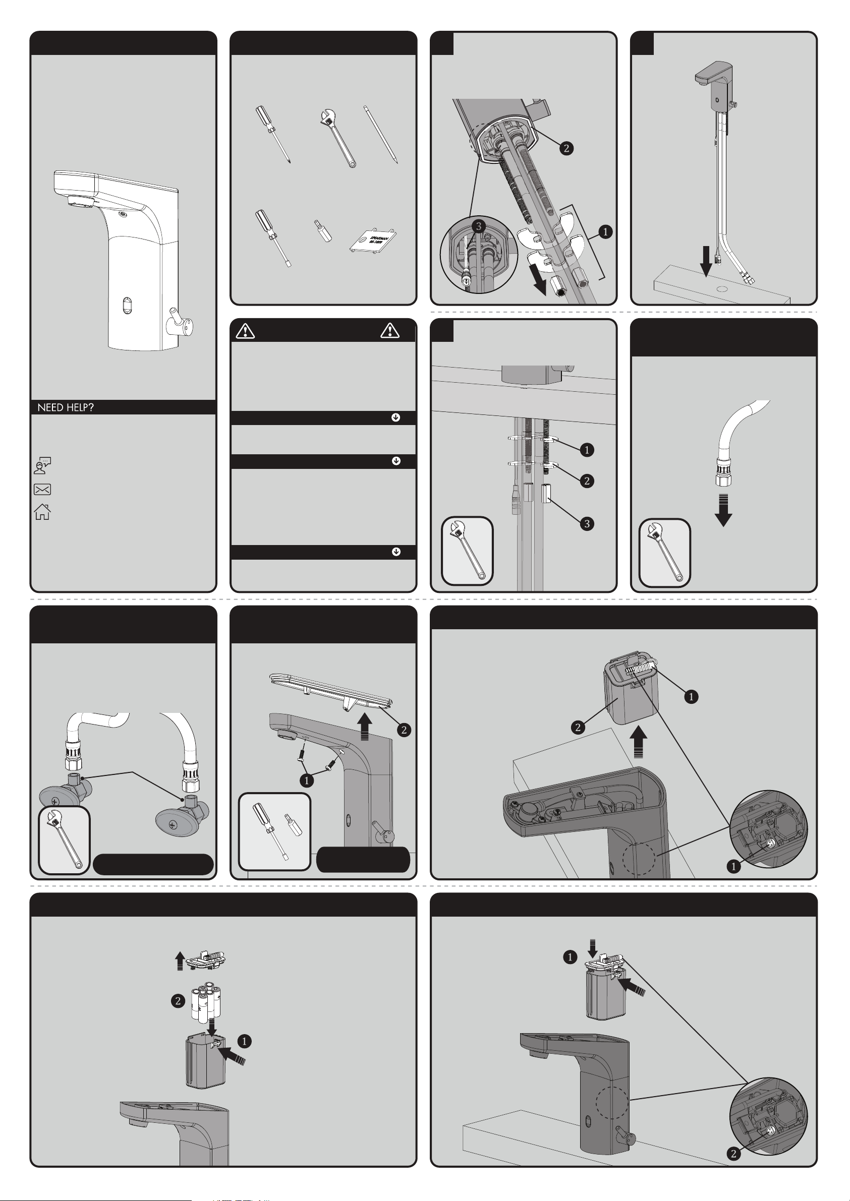
Remove Mounting Hardware (1) from faucet.
Verify that the Rubber Gasket (2) is in position
and aligned to the base of the faucet.
NOTE: If an AC Adaptor is being used, locate
the AC Connector Cable (Green) (3) inside the
faucet body and pull the connector out.
2
Place Hose carefully, one at a time, thru hole in
mounting surface. Lower Faucet into position.
3
From below, install Rubber Washer (1), Metal
Washer (2), and secure with Mounting Nuts (3).
Align Faucet to desired position and wrench
tighten Mounting Nuts (3).
4 SINGLE INLET HOSE
(SF-8700 & SF-8800)
Ensure the water supplies are turned off.
For Model SF-8700 & SF-8800: Uses a
Single Hose Mixed inlet. Attach the Hose of the
Faucet to a water supply. Wrench Tighten.
TO
WATER
SUPPLY
5 DOUBLE INLET HOSES
(SF-8702 & SF-8802)
Ensure the water supplies are turned off.
For Model SF-8702 & SF-8802: Uses two
hoses as shown below. Make connections with
the Hot and Cold hoses of the faucet to water
supplies. The inlet threads of the faucet are
9/16”-24 UNF and will accept a 3/8”
Compression Fitting. Wrench Tighten.
Accepts a 3/8”
Compression
Fitting
SUPPLY STOPS NOT INCLUDED
6 FOR BATTERY MODEL
(SF-8700 & SF-8702)
Use the provided Torx Bit tool to release the two
(2) Screws (1) and slide up to open the Lid (2) .
NOTE:
Be sure to cover your drain.
7 FOR BATTERY MODEL (SF-8700 & SF-8702)
Disconnect the GREEN Connector (1) and pull out the Battery Box (2).
8 FOR BATTERY MODEL (SF-8700 & SF-8702)
Push to release the Battery Box Cover (1). Insert or replace the batteries with six (6) new standard 1.5v AA
batteries (2). Ensure the position of the new batteries are aligned to the plus (+) and minus (-) symbols within
the battery holder.
9 FOR BATTERY MODEL (SF-8700 & SF-8702)
Install the Battery Box Cover (1) and reconnect the GREEN Connector (2). Make sure the cover is fully pressed in.
TO ITEM SHOWN, IT WILL INSTALL WITH IN
THE SAME MANNER.
Page 2
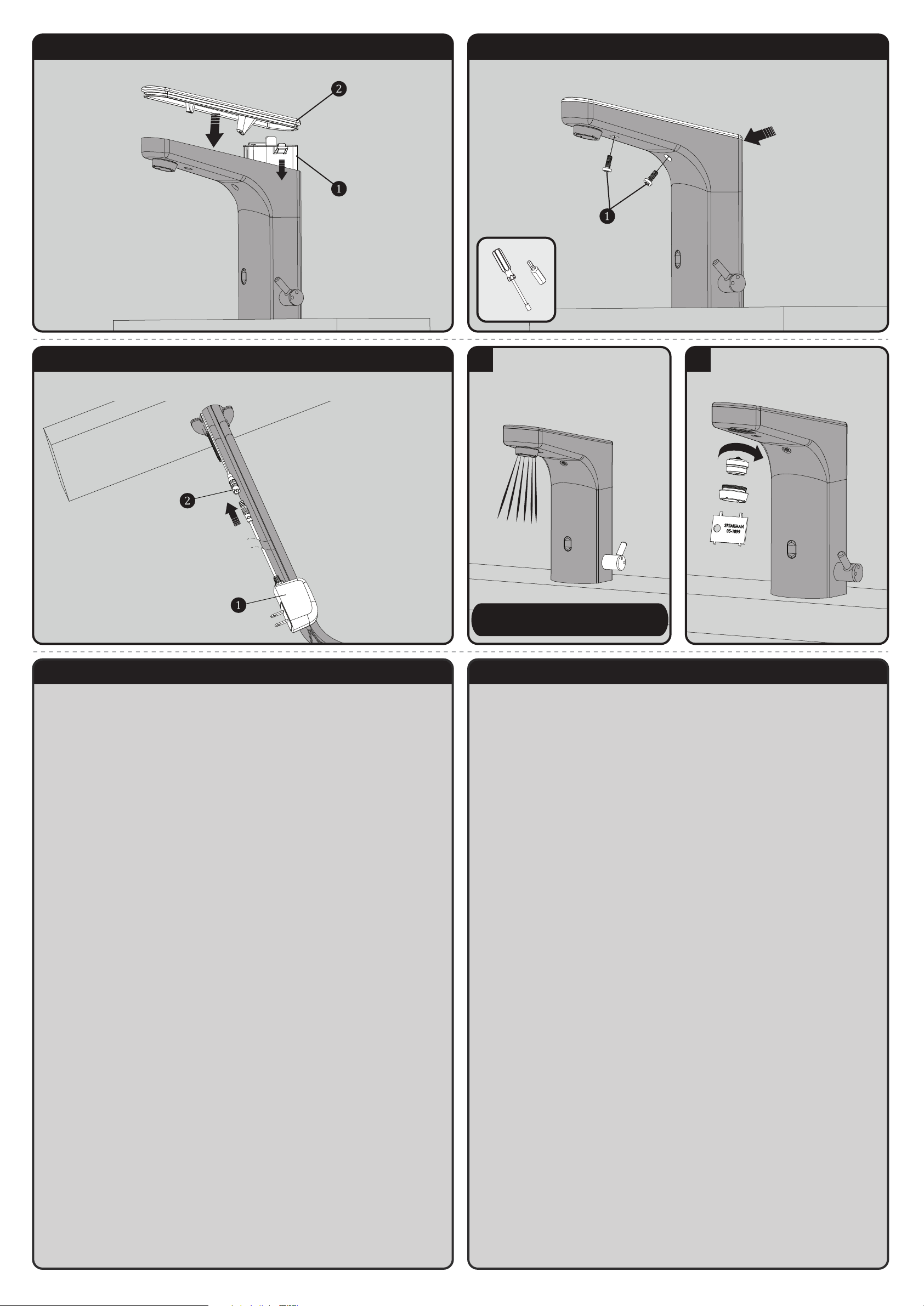
10 FOR BATTERY MODEL (SF-8700 & SF-8702)
Insert the Battery Box (1) into the Faucet Body and install the Faucet Lid (2).
11 FOR BATTERY MODEL (SF-8700 & SF-8702)
Fasten the 2 Vandal Resistant Screws (1). Make sure there are no gaps between the Lid and the Faucet Body.
12 FOR A/C MODEL (SF-8800 & SF-8802)
Verify all batteries are removed by following the previous steps. Connect the AC Adaptor (1) to the GREEN
Wire (2). Plug the A/C Adapter into the wall outlet.
13
Turn on water supplies and check for leaks.
Activate Sensor and allow Faucet to run for 1
minute to flush out any debris.
For Model SF-8702 & SF-8802: Adjust the
outlet water temperature by rotating the Mixing
Handle on the faucet.
NOTE:
If the temperature is still too cold after adjustment,
switch the HOT and COLD lines on the mixer.
14
Install Aerator. Tighten with included Aerator
Wrench.
SF-8700/SF-8800/SF-8702/SF-8802 QUESTIONS & ANSWERS
Q. How does the Sensorflo® Faucet work?
A. It uses laser technology. The Sensor emits a non-visible beam of light. When an object
enters the detection area, the Sensor signals the Solenoid Valve to open for water to flow.
When an object leaves the detection area, the Sensor signals the valve to close.
Q. Is the Sensorflo
®
Faucet sensor beam adjustable?
A. No, the Sensorflo
®
Faucet sensor beam is not adjustable. It has been factory set to
factory specifications for these Faucets.
Q. What about water conservation?
A. The Sensorflo
®
design directly addresses water conservation. Water savings of up to
85% are not unusual. Additional energy savings are realized by conserving hot water.
Q. Can the water temperature of the Sensorflo® Faucet be adjusted?
A. Yes, this Faucet has a hot and cold water mechanical mixing valve. If you need to
meet ASSE 1070, you must use our TMV (Thermostatic Mixing Valve) option.
Q. Does Sensorflo
®
reduce maintenance?
A. By elimination of on/off handles, control components are reduced and fittings stay
cleaner longer. Only a light rinsing and wiping is required to restore the beauty of the
Sensorflo
®
Faucets. Drip stains are eliminated. Fingerprints and soap spots on sinks and
fittings are avoided. Finishes last longer and wash areas stay cleaner. Germs and
bacteria are not transferred as easily making for a healthier environment.
Q. The chrome finish on my Faucet seems to be deteriorating. What can I
do to prevent this from happening?
A. Many commercial cleaning products contain harsh chemicals and abrasives. These
products should not be used on any chrome-plated plumbing products. Please use only
mild soap and water to clean the Faucet. Dry immediately with a soft cloth.
Q. Does the Sensorflo
®
system shut off immediately when an object leaves
the sensing area?
A. A very short delay of approximately 0 to 1.5 seconds occurs before water is shut off.
Q. Is my Faucet protected from power surges?
A. Yes, Sensorflo
®
has been designed to have built-in power surge protection.
Q. If we lose power, do I have to do something to get the Faucet to
operate again?
A. After a power outage, the Faucet is automatically ready for operation as soon as the
power comes back on.
Q. If I call a plumber to come and install this Faucet, will they know
enough to hook it up?
A. Our installation diagrams are very easy to follow.
SF-8700/SF-8800/SF-8702/SF-8802 TROUBLESHOOTING
If water flow from the Faucet decreases:
1) Make sure the supply stops are open.
2) Remove the Aerator from the spout using the outlet wrench. Operate the Faucet with
outlet device removed. If water flow is acceptable, disassemble the outlet device and rinse
components with clean water.
If no water flows from the Faucet, and
If you can hear a clicking sound of Solenoid opening, but no water flows:
1) Verify that the HOT and COLD wall stops are completely open.
2) If the Battery Light within the Sensor Eye blinks continuously, even when the Faucet is
not in use, the batteries within the Solenoid have low voltage and need replacement.
If you do not hear a clicking sound of Solenoid opening and no water flows:
1) If the Battery Light within the Sensor Eye blinks continuously, even when the Faucet is
not in use, the batteries within the Solenoid have low voltage and need replacement.
2) Unplug connections to Solenoid for 2 minutes. Plug connections back in. The red light
on the Sensor should turn on for several seconds before becoming operational. If not,
check power supplies and connections.
3) Disconnect the existing Solenoid Assembly and connect a new Solenoid Assembly.
Activate the Sensor and check for water flow. If the water flows, the existing Solenoid
Assembly should be replaced.
If the batteries have been replaced, but the Faucet still does not operate:
1) Check the battery polarity and electrical connections. Make sure all electrical
connections are fully inserted.
2) If the Faucet does not operate, replace the existing Solenoid Assembly with one you
know to be functioning.
If the Faucet activates, but the water will not shut off:
1) Hold a hand in front of the Sensor at up to 7" away for more than 1 minute until the
water flow stops. Once the water stops, remove your hand and wait 15 seconds. Then
place your hand in front of the Sensor and verify that it is operating properly.
2) If the Faucet still does not shut off, cover the front of the sink with a towel. This will
eliminate the potential of reflections activating the Sensor.
3) If it is a new installation and still not working, replace the Solenoid Assembly.
Page 3
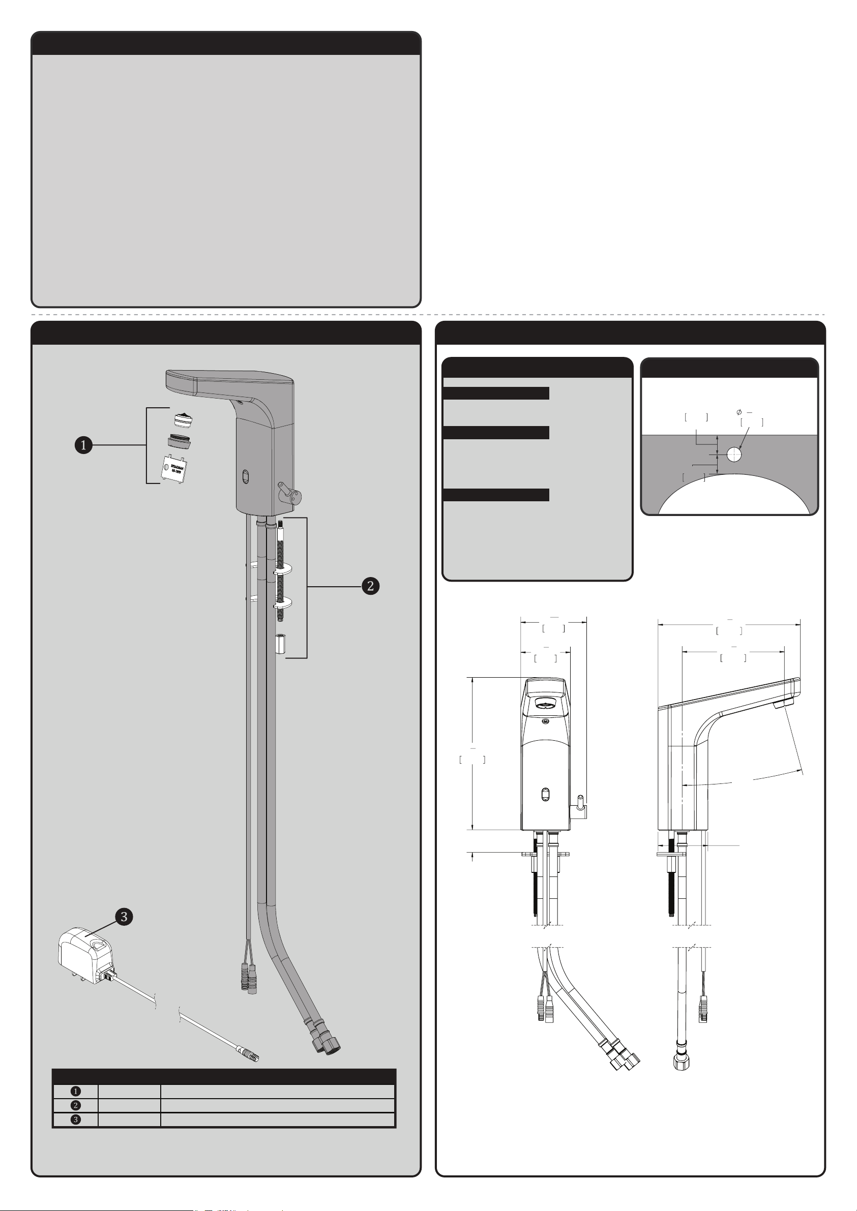
SF-8700/SF-8800/SF-8702/SF-8802 REPAIR PARTS
ITEM NO. PART NO. DESCRIPTION
RPG05-108059 0.5 GPM AERATOR REPAIR KIT
RPG45-110196 MOUNTING HARDWARE GROUP
RPG76-107259 TRANSFORMER 120VAC TO 6VDC
NOTES:
COMPLIANCE:
CONNECTIONS:
ASME A112.18.1/CSA B 125.1
Supply Connection:
9/16"-24 UNF Connection
FLOW DATA:
• 0.5gpm (1.9 L/min)
2"
MIN. TO LEDGE
51mm
2"
MIN. TO WALL
51mm
LAVATORY ROUGH-IN
32mm
1
1
4
"
MIN
SF-8700/SF-8800/SF-8702/SF-8802 ROUGH-IN DIAGRAM
ALL DIMENSIONS ARE IN INCHES (MILLIMETERS) UNLESS
OTHERWISE SPECIFIED. DIMENSIONS SUBJECT TO
CHANGE WITHOUT NOTICE.
SF-8700/SF-8800/SF-8702/SF-8802 CARE AND CLEANING
1) Your SENSORFLO® Faucet is designed and engineered in accordance with the highest
quality and performance standards. With proper care, it will provide years of hygienic
and trouble-free service.
2) Periodically, the Faucet will require some minor maintenance to keep it at peak
performance. There is a low battery indicator located on the Sensor on the Faucet body.
When the low battery light on the Sensor blinks, it indicates that the battery is low. To
replace the batteries, follow the installation instructions in the electrical connections section
of this document.
3) Periodically clean the In-Line Filter.
4) The polished chrome finish of your Faucet should be cleaned using mild soap and
warm water.
5) Dry immediately with a soft, clean cloth for best results.
6) NEVER use abrasive cleaners, chemicals, alcohol or other solvents. They may damage
the surfaces of the non-chrome plated finishes.
7
6
"
8
174mm
3"
MAX DECK
THICKNESS
15
2
"
16
75mm
1
2
"
4
57mm
163mm
117mm
3
6
8
4
"
5
"
8
15.00°
MIN DECK
HOLE SIZE
1 1/4"
Page 4
INSTRUCTIONS FOR MODELS
92-A-TMV-02
For additional assistance or service please contact:
SPEAKMAN
®
800-537-2107
www.speakman.com
A-TMV
Thermostatic Mixing Valve
HELPFUL TOOLS & SUPPLIES:
TOOLS AND SUPPLIES
Thermometer Measuring
IMPORTANT
• Compliance and conformity to local codes and
ordinances is the responsibility of the installer.
• Valve should be accessible for testing, adjustment
and maintenance in the installed position.
• Make sure that all water supply lines have been
flushed and then completely turned off before
beginning installation. Debris in supply lines can
cause valves to malfunction.
• Ensure the mounting structure and mounting
hardware can safely support the product in use.
• Do not over-tighten any connections or damage
may occur.
• Be sure to read instructions thoroughly before
beginning installation.
Be sure to wear eye protection.
SAFETY TIPS
Warranty information can be found at:
www.speakman.com
WARRANTY
See section “Testing the Mixing Valve”.
MAINTENANCE
IMPORTANT
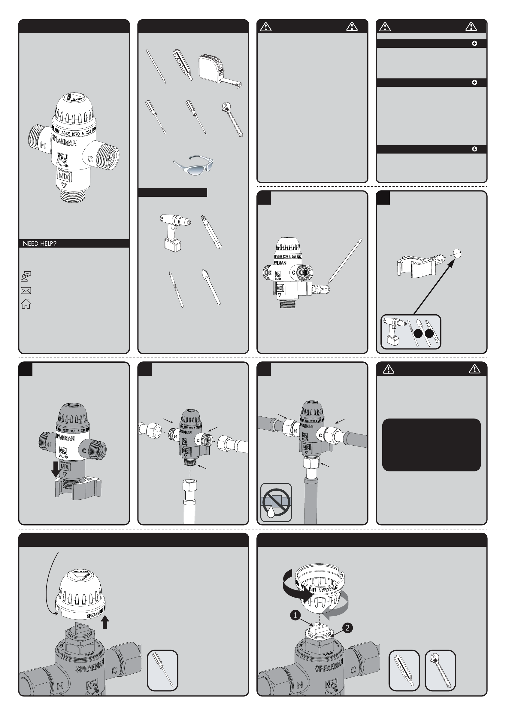
1
Determine desired mounting position of the
A-TMV with Plastic Wall Bracket. Ensure
mounting location is capable of supporting the
product in use. Using a pencil, mark the hole
location.
2
If mounting to drywall or tile, select appropriate
5/16" drill bit and drill guide hole at marked
location. Install the Plastic Wall Bracket into the
drilled hole and press/tap into place until the
bracket is flush to the wall surface. Secure the
Plastic Wall Bracket to the wall with the proper
Mounting Screw (included).
Ø5/16”
OR OR
3
Ensure the A-TMV is vertical and the body rests
on the top face of the Plastic Wall Bracket.
4
Connect Supply Lines and Fixtures.
• Ensure incoming water supplies are turned OFF.
• Install Inlet and Outlet connections to the valve.
Wrench Tighten.
HOT
INLET
COLD
INLET
TEPID WATER
OUTLET
5
• Check for leaks by pressurizing the unit SLOWLY.
• Check the temperature and adjust if necessary.
HOT
INLET
COLD
INLET
TEPID WATER
OUTLET
CAUTION
When maintaining and
adjusting the Mixing Valve, all
fixtures should be isolated from
use. Speakman recommends
that appropriate personnel
shall work safely at all times.
6 SETTING THE MIXING VALVE
Should the Valve require adjustment, or an
application require a different set temperature,
proceed as follows:
Adjust Temperature with Water Running
• Check the temperature with a stick thermometer.
• Contact proper medical and safety authorities
to determine the correct water temperature for
the specific application.
• Remove the Plastic Cap (White) from the Valve
using a flat tip screwdriver.
REMOVE THE CAP WITH
FLAT TIP SCREWDRIVER
FROM THE NOTCH
ON THE CAP
7 SETTING THE MIXING VALVE
• Create a draw on the Mixing Valve by opening
the faucet.
• Loosen, but do not remove the Locking Nut (2)
using adjustable wrench. Invert Plastic Cap and
align triangular recess in cap to the Adjuster
Screw (1).
• Set the outlet temperature by turning the Adjuster
Screw clockwise to reduce temperature,
counterclockwise to increase temperature.
Use a stick Thermometer to check the outlet
temperature.
• Tighten the Locking Nut to avoid inadvertent
adjustment of outlet temperature.
WARMER
COLDER
Pencil
Tape
Flat Tip
Screwdriver
Drill
Drill Bit
5
Ø
/16”
Phillips
Screwdriver
Safety
Glasses
Drive Bit
Tile Drill Bit
Ø
Phillips
5
/16”
Adjustable
Wrench
Page 5
8 TESTING THE MIXING VALVE
After installation, test the Mixing Valve and the faucet it
serves for proper operation by following the steps below.
Valve temperature test procedure is as follows:
1. Activate faucet to observe and record the temperature with a stick
Thermometer. If the temperature of the Thermometer is not correct,
readjust the Mixing Valve according to the section “Setting the Mixing
Valve”.
9 REPLACING THE THERMOSTATIC ELEMENT
The Thermostatic Element’s replacement procedure is
as follows:
1. Shut off the hot water supply and cold water supply to the Mixing Valve.
2. Remove the Plastic Cap and disassemble the Valve Cap.
3. Remove Thermostatic Element in conjunction with the Shuttle from the
Valve Body. No special tools are required.
4. Inspect the Thermostatic Element. If it feels slippery to the touch,
then the Element has lost its wax and requires replacement. If the
Thermostatic Element feels normal to the touch, then it is in good
condition and operable.
5. Verify that the stainless steel Piston moves freely up and down within
the Element’s body.
Note:
Gallon per minute ratings may
vary depending upon incoming
water temperatures and
pressures. Hot and cold water
inlet pressures must be equal.
Provisions shall be made to
thermally isolate the valve.
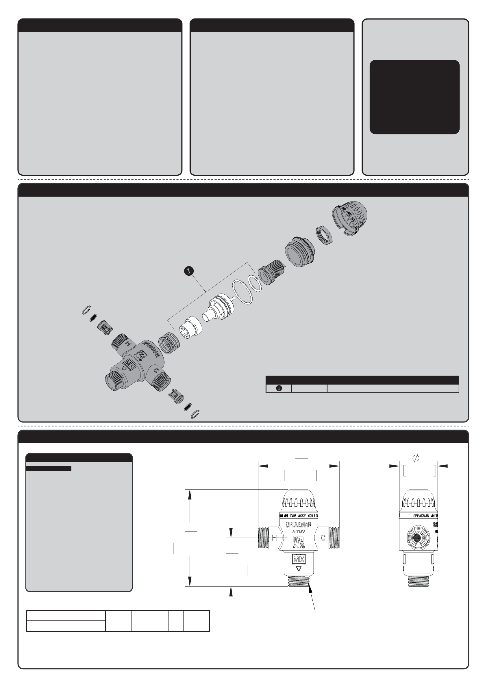
A-TMV REPAIR PARTS
SPEAKMAN
®
RPG05-109269 THERMOSTATIC & O-RING REPAIR KIT
ITEM NO. PART NO. DESCRIPTION
A-TMV ROUGH-IN DIAGRAM
SPEAKMAN
®
NOTES:
COMPLIANCE:
ASSE 1070 & cUPC Certified
• Inlets: 3/8” Compression Male Threads
• Outlet: 3/8” Compression Male Threads
• Maximum Working Pressure: 125 psi (861.9 kPa)
• Rated flow at 30 psi (206.9 kPa) differential
pressure: 2.16 GPM (8.2 L/min)
• Minimum flow rate: 0.35 GPM (1.3 L/min)
• Hot Water Inlet Temperature Range: 120° – 180° F
• Cold Water Inlet Temperature Range: 37° – 80° F
• Outlet Water Temperature Range: 80° – 120° F
• Minimum Temperature Differential (Hot to Mix):
18° F (10° C)
Contractor to supply necessary inlet
connections.
FLOW CAPACITY OF A-TMV
PRESSURE DROP,
psi (bar)
TEMPERED FLOW,
GPM (L/min)
50
(3.4)
2.8
(10.6)
2
9
16
"
66mm
1
5
16
"
33mm
2
3
16
"
55mm
9/16"-24 THREAD FOR
3/8" COMPRESSION FITTINGS
(3 PLACES)
1"
26mm
NOTES:
ALL DIMENSIONS ARE IN INCHES [MILLIMETERS] UNLESS OTHERWISE
1.
SPECIFIED AND ARE SUBJECT TO CHANGE.
5
(0.4)10(0.7)15(1.0)20(1.4)30(2.1)40(2.8)45(3.1)
0.66
1.2
1.5
(2.5)
(4.5)
(5.7)
1.74
(6.6)
2.16
2.51
(8.2)
(9.5)
2.66
(10.1)
 Loading...