

Page 1
INSTRUCTIONS FOR MODELS
92-SB-255X-01
For additional assistance or service please contact:
SPEAKMAN
®
800-537-2107
www.speakman.com
SB-2551
SB-2552
SB-2553
HELPFUL TOOLS & SUPPLIES:
TOOLS AND SUPPLIES
Adjustable
Wrench
Slip Joint
Wrench
Thread Seal
Tape
Aerator
Wrench
(included)
Phillips
Screwdriver
Safety
Glasses
Plumber’s
Putty
Hex Key
Wrenches
(included)
Level
Drill Drill Bit
1/8”
Warranty information can be found at:
www.speakman.com
WARRANTY
Your new Speakman Product is designed for years of
trouble-free performance. Keep it looking new by
cleaning it periodically with a soft cloth. The use of harsh
chemicals and abrasives on any of the Speakman custom
finish products may damage the finish and void the
product warranty. Please be sure to only use approved
cleaners. Please contact Speakman for any clarification
of acceptable cleaners.
MAINTENANCE
Cover your drain to prevent loss of parts. Be sure to
wear eye protection while cutting pipe.
SAFETY TIPS
IMPORTANT
• Be sure to read instructions thoroughly before
beginning installation.
• Do not over-tighten any connections or damage
may occur.
• This faucet has an operating range of 20-80 psi.
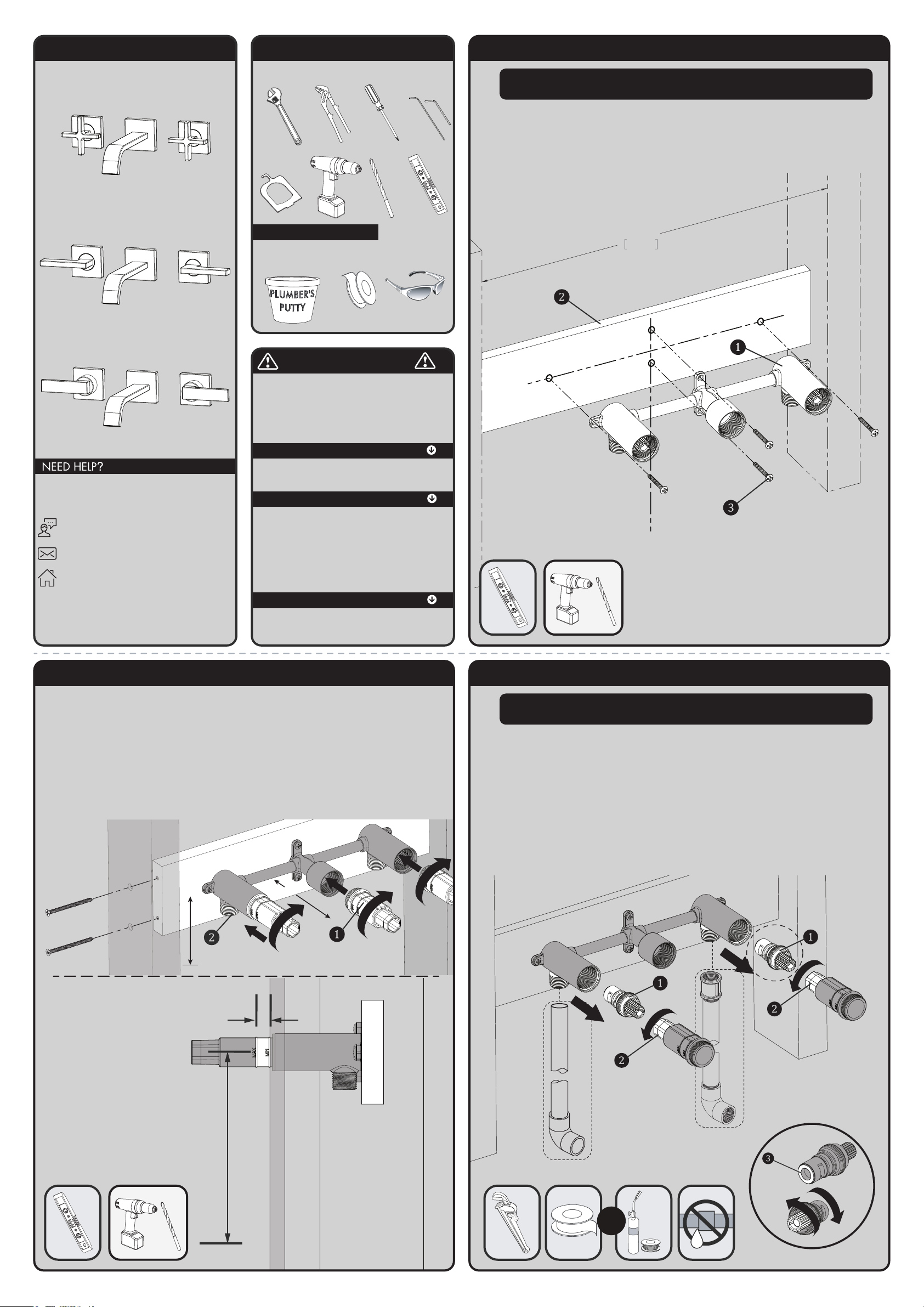
1 ASSEMBLE FAUCET BODY TO CROSS BEAM
• Assemble Faucet Body (1) to 1X4 piece of wood (2) using a Drill and 1/8” Drill Bit to start
holes for supplied Mounting Screws (4 in total). Use level if needed to make sure Faucet Body is
straight before starting holes. Ensure Spout Outlet Port is aligned vertically with the drain
location.
• Attach Faucet Body to 1X4 piece of wood by screwing Mounting Screws (4 in total) (3) into
mounting holes.
16"
406mm
ALIGN
WITH
DRAIN
NOTE:
Measure the distance between the 2 vertical studs. Cut a 1x4” board to this length.
2
ASSEMBLE CROSS BEAM TO STUDS USING ROUGH-IN SLEEVES
• Assemble Rough-in Sleeves (3 in total) (1) to Faucet Body as shown below.
• Determine Mounting Height of Faucet “A”.
• IMPORTANT: Using the Max. – Min. ribs on the Rough-In Sleeves, determine rough-in depth by
locating front surface of mounting wall in between Rough-In Sleeve ribs “B”. Position the Faucet
Body and Cross Beam within the wall cavity. The mounting depth shall be aligned so the
finished wall surface will fall between the MAX-MIN markings on the rough-in
sleeves. Make sure back side of cross beam does not extend beyond the back side of 2X4 stud.
• Once rough-in depth is established, assemble Cross Beam to 2X4 studs behind mounting wall.
Make sure Threaded Body Inlets (2) are facing downward. Mounting hardware not included.
• Once Faucet Body is installed, remove Rough-In Sleeves (3 in total) from Faucet Body
“B”
“A”
“A”
MOUNTING
HEIGHT
“B”
ROUGH-IN
DEPTH
3 ASSEMBLE COPPER PIPE
• Remove Hot/Cold cartridges (1) from faucet body, using the Hex Drive end (2) of the Rough-In
Sleeves. Pull cartridges out of the faucet body.
• Solder ½” Copper Pipe “A” (not included) to the inlets at the bottom of the hot/cold handle
sleeves of the faucet body. Or make Threaded Connections “B” (not included).
• Re-install cartridges inside the faucet body. Make sure cartridge is inserted in the correct side
(Hot or Cold) by noticing Color of Seal (3) at bottom and by turning cartridge stem. Hot cartridge
should only turn clockwise to “On” position. Cold cartridge should only turn counter-clockwise to
“On” position.
• Important: Turn cartridges to “Off” position.
• Turn on water supplies and check for leaks.
• Turn off water supplies.
• Reinstall Rough-In Sleeves to protect the components during finished wall construction.
THREADED PIPE FITTING
COPPER SWEAT FITTING
OR
HOT
“A”
“B”
COLD
NOTE: If making threaded connections for the inlet supplies,
removal of hot/cold cartridges is not required.
HOT
COLD
Page 2
IMPORTANT:
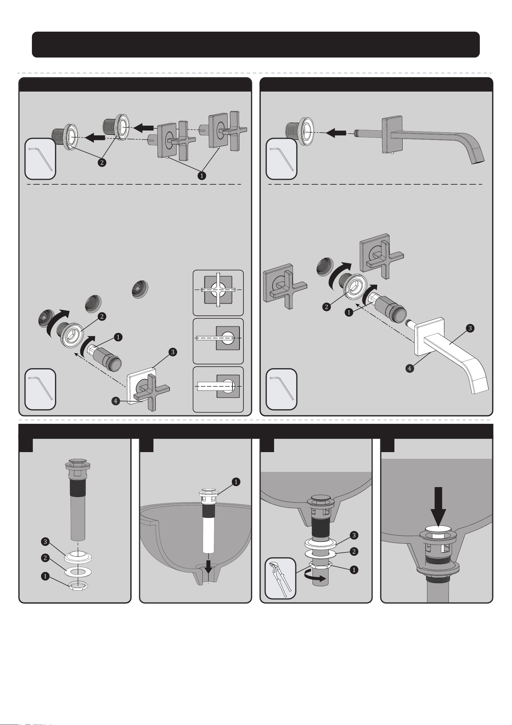
4 ASSEMBLE HANDLES TO FAUCET BODY
• Loosen but do not remove Set-Screws (1) from flanges of handles using the included Hex Key
and remove Threaded Sleeves (2) from assembly.
• Remove Rough-In Sleeves from faucet.
• Using the Hex Post (1) at the front of one of the rough-in sleeves, assemble the Threaded
Sleeves (2) to the hot and cold handle inlets of the faucet body. Make sure to screw the threaded
sleeves tightly to the front of the mounting wall.
• With the cartridge in the "Off" position, align handle to desired "Off" position, and engage
the splines of the valve into the handle assembly.
• Take the top half of the handle assembly and install onto the threaded sleeves. Make sure there
is engagement between the female spline of the handle assembly and the male spline found
inside the handle inlet.
• Rotate Handle Flange (3) until Set-Screw is facing downward. Tighten Set-Screw (4) using the
included Hex Key to lock flange in place.
• Rotate the handle from the "Off" position to the "On" position and back again. Verify proper
alignment of handle in the "Off" position.
SB-2551
HANDLE ALIGNMENT
SB-2552
HANDLE ALIGNMENT
SB-2553
HANDLE ALIGNMENT
5 ASSEMBLE SPOUT TO FAUCET BODY
• Loosen but do not remove Set-Screw (1) from flange of spout and remove Threaded
Sleeve (2) from assembly using the included Hex Key.
• Using the Hex Post (1) at the front of one of the rough-in sleeves, assemble the Threaded
Sleeve (2) of the spout assembly to the faucet body. Make sure to screw the threaded
sleeve tightly to the front of the mounting wall.
• Take the Spout (3) of the faucet assembly and install onto the threaded sleeve. Make
sure outlet of spout is facing downward.
• Tighten Set-Screw (4) using the included Hex Key to lock spout in place.
6
Remove Mounting Nut (1), Metal Washer
(2), and Sealing Washer (3) from Drain
Assembly.
7
Apply included Upper Drain Seal (1) or
Plumber’s Putty to the underside of the
Upper Flange. Insert Drain Assembly into
drain hole of sink from above.
8
From below, install Sealing Washer (3),
Metal Washer (2), and secure with
Mounting Nut (1). Tighten with Slip Joint
Pliers. Take care to not over-tighten
connection.
9
Test Drain operation by pressing down on
Stopper to open/close Drain.
Complete wall construction and finish surfaces before continuing installation.
DRAIN ASSEMBLY
Page 3
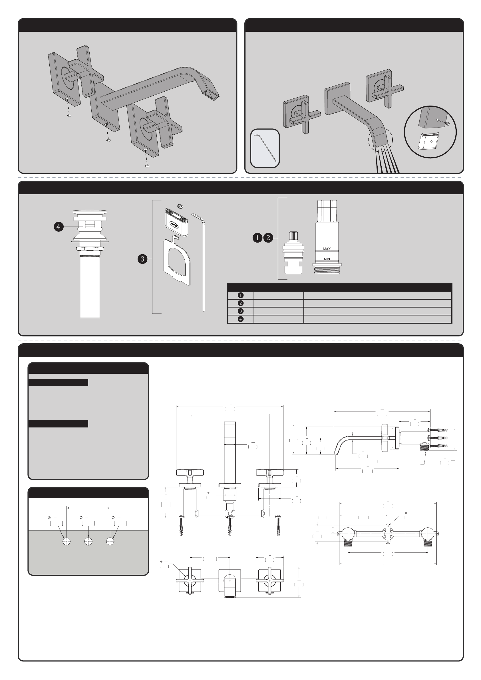
10 INSTALL RUBBER CAPS
• Install the Rubber Caps (X3) in the flanges of the handles and spout set screws.
11 FLUSH SYSTEM
• Turn on Water Supplies and Check for Leaks.
• Turn on faucet to flush system.
• After flushing is complete, turn off the water and install Aerator to spout and secure into
position using the included Hex Wrench.
• Align threaded hole of Aerator towards the rear as shown. Lock Aerator in place by tightening
Aerator Set Screw with the included Hex Key.
BACK VIEW OF SPOUT
SB-255X REPAIR PARTS
SPEAKMAN
®
RPG05-109263 HOT WATER REPLACEMENT CARTRIDGE WITH ROUGH-IN SLEEVE
RPG05-109262 COLD WATER REPLACEMENT CARTRIDGE WITH ROUGH-IN SLEEVE
RPG05-106849 AERATOR BAG GROUP
S-3470-XX (XX = FINISH) REPLACEMENT "PUSH ACTIVATED" DRAIN ASSEMBLY WITH NO SPEAKMAN
ITEM NO. PART NO. DESCRIPTION
SB-2551 ROUGH-IN DIAGRAM
SPEAKMAN
®
DIMENSIONS SUBJECT TO CHANGE WITHOUT NOTICE.
NOTES:
COMPLIANCE:
FLOW:
ASME A112.18.1/CSA B 125.1
AB1953
NSF 372
NSF 61
Flow Rate: 1.2 gpm
Flow Type: Aerated
Contractor to supply necessary connections
to the inlets of the end bodies.
LAVATORY ROUGH-IN
32mm
1
1
4
"
MIN
8”
32mm
1
1
4
"
MIN
32mm
1
1
4
"
MIN
6
3
8
"
162mm
2
3
4
"
70mm
3"
76mm
1
5
8
"
41mm
2
3
4
"
70mm
3
1
16
"
78mm
1/2" NPT INLETS
[12mm]
2
1
4
"
57mm
2
1
4
"
58mm
3
1
8
"
79mm
9
11
16
"
246mm
3
8
"
10mm
8"
203mm
3
5
8
"
3
1
8
"
92mm
79mm
ROUGH-IN RANGE OF
1/2" ADJUSTABILITY
10
3
4
"
273mm
1
3
4
"
45mm
2
1
4
"
57mm
1
1
4
"
32mm
1
3
16
"
30mm
1
3
16
"
31mm
4.00in
101.60mm
8"
203mm
9
3
4
"
248mm
1
9
16
"
40mm
4
7
8
"
124mm
9
3
4
"
248mm
3
16
"
5mm
13
16
"
20mm
Page 4
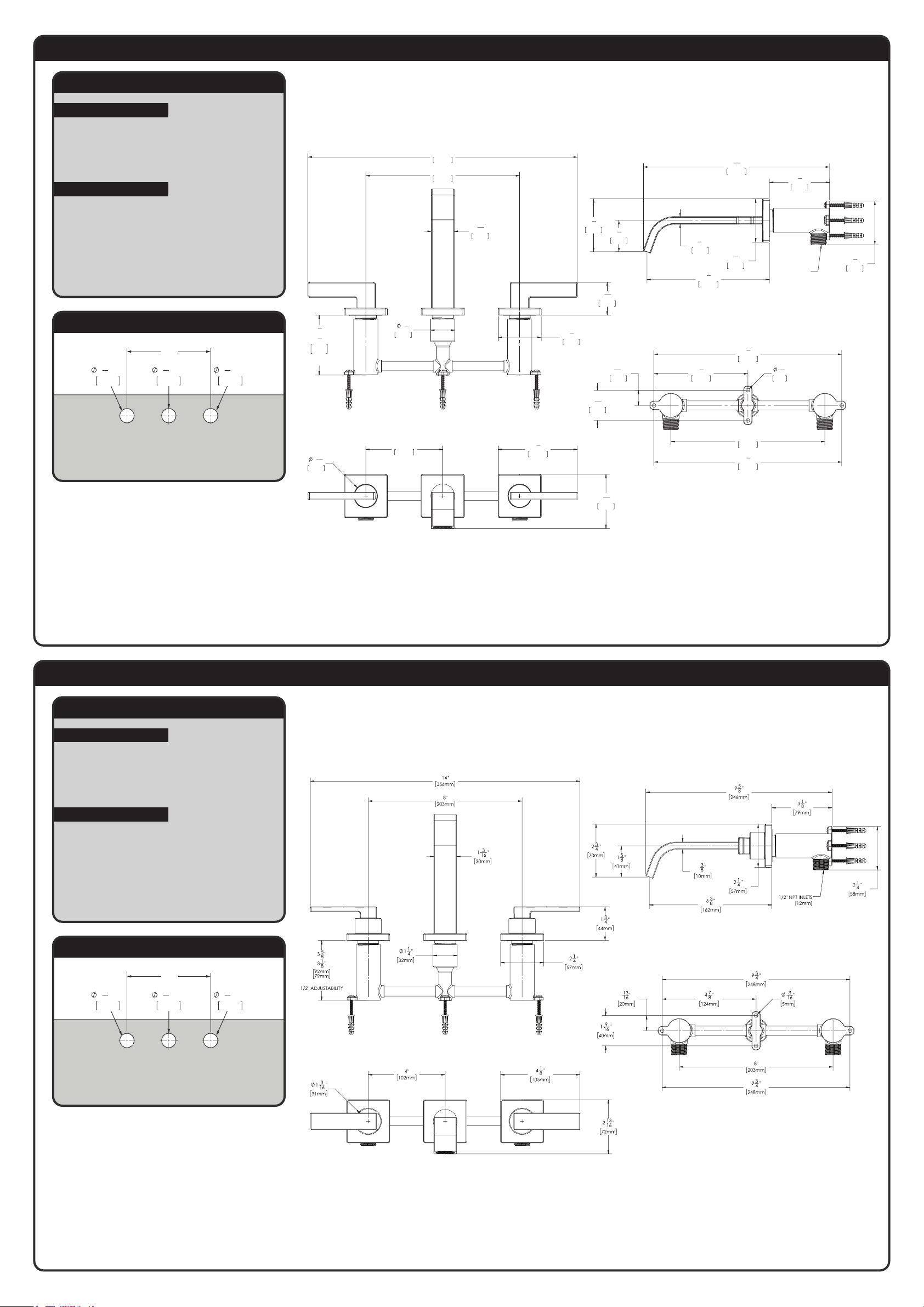
SB-2552 ROUGH-IN DIAGRAM
SPEAKMAN
®
DIMENSIONS SUBJECT TO CHANGE WITHOUT NOTICE.
NOTES:
COMPLIANCE:
FLOW:
ASME A112.18.1/CSA B 125.1
AB1953
NSF 372
NSF 61
Flow Rate: 1.2 gpm
Flow Type: Aerated
Contractor to supply necessary connections
to the inlets of the end bodies.
LAVATORY ROUGH-IN
32mm
1
1
4
"
MIN
8”
32mm
1
1
4
"
MIN
32mm
1
1
4
"
MIN
14"
356mm
4
1
8
"
105mm
2
13
16
"
72mm
6
3
8
"
162mm
2
3
4
"
70mm
1
5
8
"
41mm
8"
203mm
3
5
8
"
3
1
8
"
92mm
79mm
ROUGH-IN RANGE OF
1/2" ADJUSTABILITY
2
1
4
"
57mm
1
11
16
"
43mm
1
1
4
"
32mm
1
3
16
"
30mm
1
3
16
"
31mm
4"
102mm
1/2" NPT INLETS
[12mm]
2
1
4
"
57mm
3
1
8
"
79mm
2
1
4
"
58mm
9
11
16
"
246mm
3
8
"
10mm
8"
203mm
9
3
4
"
248mm
1
9
16
"
40mm
13
16
"
20mm
9
3
4
"
248mm
4
7
8
"
124mm
3
16
"
5mm
SB-2553 ROUGH-IN DIAGRAM
SPEAKMAN
®
DIMENSIONS SUBJECT TO CHANGE WITHOUT NOTICE.
NOTES:
COMPLIANCE:
FLOW:
ASME A112.18.1/CSA B 125.1
AB1953
NSF 372
NSF 61
Flow Rate: 1.2 gpm
Flow Type: Aerated
Contractor to supply necessary connections
to the inlets of the end bodies.
LAVATORY ROUGH-IN
32mm
1
1
4
"
MIN
8”
32mm
1
1
4
"
MIN
32mm
1
1
4
"
MIN
ROUGH-IN RANGE OF
 Loading...