

Page 1
INSTRUCTIONS FOR MODELS
92-S-5122-02
For additional assistance or service please contact:
SPEAKMAN
®
800-537-2107
www.speakman.com
S-5122
* MODEL SHOWN WITH OPTIONAL DECKPLATE
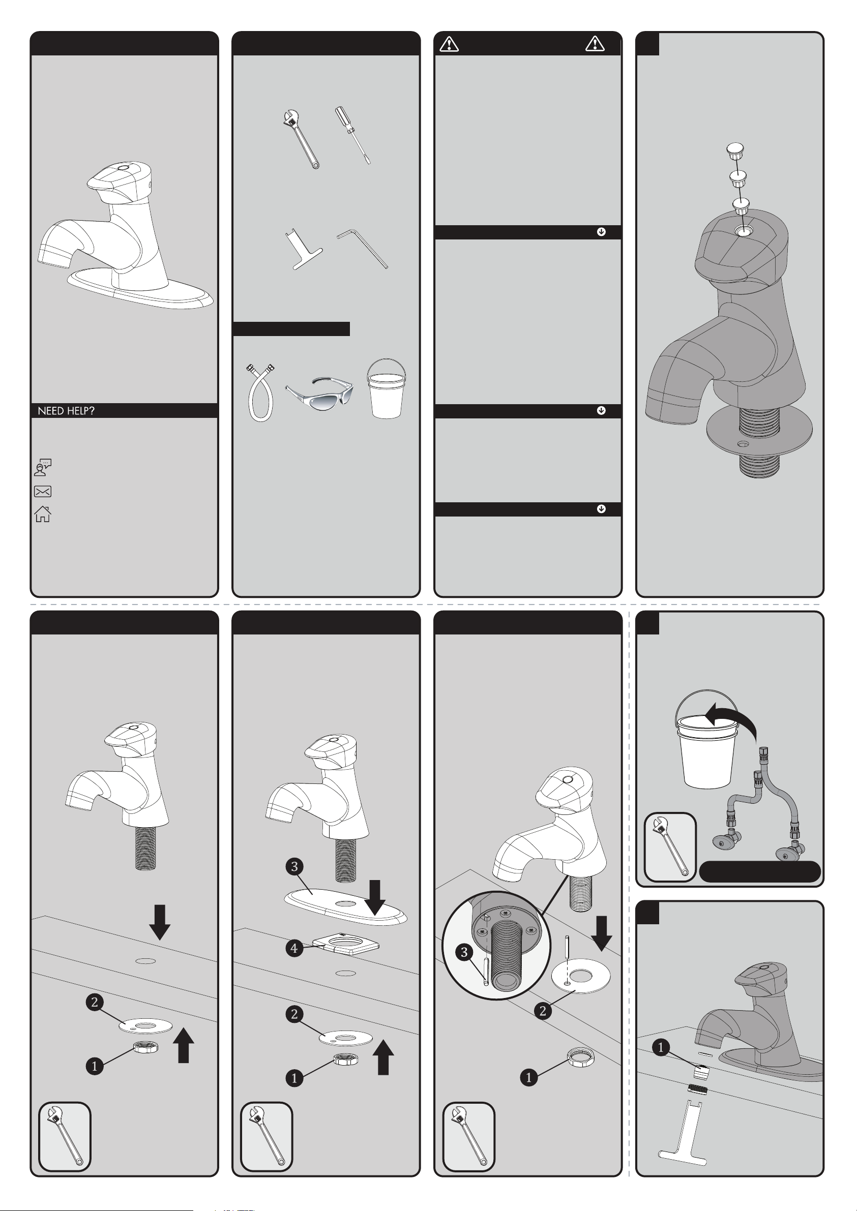
HELPFUL TOOLS & SUPPLIES:
TOOLS AND SUPPLIES
Adjustable
Wrench
Flat Tip
Screwdriver
Supply
Hoses
Safety
Glasses
Aerator
Wrench
(Included)
Bucket
Hex Key
Wrench
(Included)
Warranty information can be found at:
www.speakman.com
WARRANTY
MAINTENANCE
IMPORTANT
Cover your drain to prevent loss of parts.
SAFETY TIPS
Your new Speakman Product is designed for years of
trouble-free performance. Keep it looking new by
cleaning it periodically with a soft cloth. The use of
harsh chemicals and abrasives on any of the Speakman
custom finish products may damage the finish and void
the product warranty. Please be sure to only use
approved cleaners. Please contact Speakman for any
clarification of acceptable cleaners.
Metering Faucets are very sensitive to impurities within
a water supply that may lead to poor performance
or malfunction.
If you are in an area with poor water quality, it is
recommended to install a secondary in-line filtration
system. This in-line filtration system should be installed
upstream (before) the inlets of the Metering Faucet.
• Be sure to read instructions thoroughly before
beginning installation.
• Do not over-tighten any connections or damage
may occur.
• This faucet has an operating range of 20-80 psi.
1
Three (3) Handle Indicators are supplied, Cold
(Blue), Hot (Red) and Tepid (Grey). Decide which
indicator is to be used and install in the Handle
Assembly.
2A NO DECKPLATE
Shut off water supplies. Remove old faucet.
Clean mounting surface in preparation of new
faucet.
• Remove Mounting Nut (1) and Washer (2).
Place Faucet through Mounting Hole in sink.
Secure Faucet to sink using Mounting Nut and
Washer provided. Wrench tighten.
2B WITH DECKPLATE
Shut off water supplies. Remove old faucet.
Clean mounting surface in preparation of new
faucet.
• Remove Mounting Nut (1) and Washer (2).
Place Deckplate (3) and Retainer/Gasket (4) on
bottom of new faucet. Place Faucet through
Mounting Hole in sink. Secure Faucet to sink
using Mounting Nut and Washer provided.
Wrench tighten.
2C WITH PIN
Shut off water supplies. Remove old faucet.
Clean mounting surface in preparation of new
faucet.
• Remove Mounting Nut (1) and Washer (2).
Using Washer as a template over the hole in
sink, mark the location and drill a through hole
using a 1/8” Drill Bit. Insert a 1/8” X 1”
Nominal Stainless Steel Slotted Spring Pin (not
included) (3) into the hole located on the bottom
of the faucet. Place the Faucet with Pin through
the mounting hole in the sink. Secure Faucet to
sink using Mounting Nut and Washer provided.
Align the hole in the washer with the pin if deck
thickness permits. Wrench tighten.
3
Make connections to water supply. Use ½”-14
NPSM faucet connections. Use wrenches to
tighten connections. Do not overtighten. Inlet
supply flexible hoses and valve stops are not
included. Place free ends of hoses into a bucket.
Turn on water supplies for one (1) minute to flush
debris from the system. Connect water supply to
inlet of Metering Faucet.
INLET SUPPLIES NOT INCLUDED
4
IMPORTANT: After installation is completed,
use supplied Aerator Wrench to remove Aerator
(1). Turn on water supplies and allow water to
run. While water is running, check for leaks.
Wait for the water to stop and replace Aerator.
Page 2
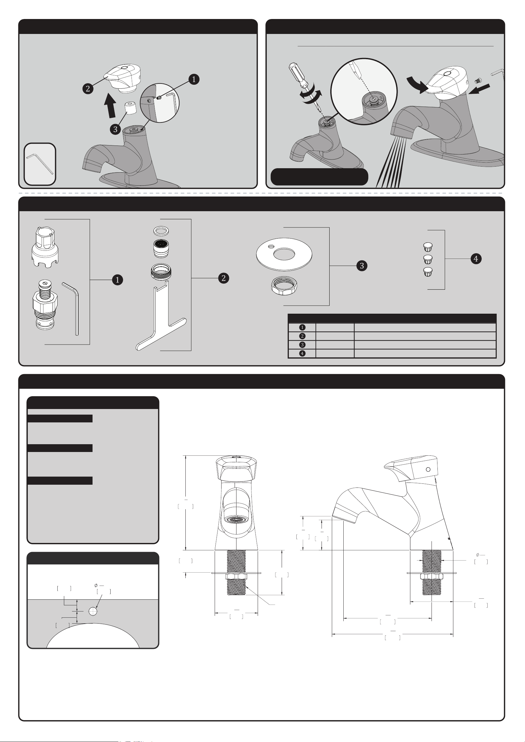
S-5122 REPAIR PARTS
SPEAKMAN
®
RPG05-108759 METERING VALVE
RPG05-109171 AERATOR
RPG05-108765 MOUNTING HARDWARE
RPG05-108060 HANDLE INDICATORS
ITEM NO. PART NO. DESCRIPTION
S-5122 ROUGH-IN DIAGRAM
SPEAKMAN
®
DIMENSIONS SUBJECT TO CHANGE WITHOUT NOTICE.
4
1
4
"
108mm
1
15
16
"
49mm
3
15
16
"
100mm
1
3
8
"
34mm
1
1
2
"
39mm
1
15
16
"
49mm
5
7
16
"
138mm
1/2"-14 NPSM THD
1"
25mm
MAX DECK THICKNESS
2"
51mm
13
16
"
21mm
MIN DECK HOLE
2"
MIN. TO LEDGE
51mm
2"
MIN. TO WALL
51mm
LAVATORY ROUGH-IN
21mm
13
16
"
NOTES:
COMPLIANCE:
CONNECTIONS:
ASME A112.18.1/CSA B 125.1
FLOW DATA:
0.25gpc (0.95 L/cycle)
Supply Connection:
1/2"-14 NPSM Connection
Contractor to supply necessary inlet
connections.
TIMING ADJUSTMENT 1
The spray timing is pre-adjusted at the factory. However, due to different field conditions, this adjustment may need to
be modified at the time of installation. Begin by removing the Screw (1) from the back side of the Faucet using the
supplied Hex Wrench. Lift the Handle Assembly (2) to remove and place aside.
Remove the Cartridge Cap (3) and place aside.
TIMING ADJUSTMENT 2
Using a Flat Tip Screwdriver, either thread in or out the end screw of the metering cartridge to adjust the duration of the
spray timing. IMPORTANT: Do NOT screw more than 1 complete rotation in either direction or damage may occur.
Replace the Cartidge Cap and Handle Assembly and press down on the handle to test spray duration. Once proper
timing is achieved replace the Screw to the back of the faucet and tighten.
¼ CLOCKWISE = INCREASE RUN TIME
¼ COUNTER CLOCKWISE = DECREASE RUN TIME
 Loading...