

Page 1

®
SPEAKMAN
SLV-1050
Installation, Operation & Maintenance Instructions
NEO™ COLLECTION COMBINATION SERIES
DESCRIPTION
Speakman Neo™ Collection Combination Series, SLV-1050 includes: Trim (CPT-1001), Low Flow Multi
Function Hand Shower (VS-3010-E2), ADA Pause Switch (VS-156), Supply Ell (VS-155), Slide Bar (SA-1002),
and Diverter Tub Spout (S-1558). This combination does not include the Shower Valve.
This combination should be installed with one of the following
Speakman Sentinel Mark II® Pressure Balance Shower Valves
CPV-PB: Thermostatic Shower Valve
Sweat & Thread Connections
CPV-PB-PXC: Thermostatic Shower Valve
PEX F1807 Crimp Inlet Connections
CPV-PB-PXE: Thermostatic Shower Valve
PEX F1960 Cold-Expansion Inlet Connections
This combination should be installed with one of the following
Speakman Sentinel Mark II® Thermostatic Shower Valves
CPV-T: Thermostatic Shower Valve
Sweat & Thread Connections
CPV-T-PXC: Thermostatic Shower Valve
PEX F1807 Crimp Inlet Connections
CPV-T-PXE: Thermostatic Shower Valve
PEX F1960 Cold-Expansion Inlet Connections
SPECIFICATIONS
CPT-1001 SENTINEL MARK II® SHOWER VALVE TRIM:
COMPLIANCE: ASME A112.18.1 / CSA B125.1 Standard
VS-3010-E2 LOW FLOW MULTI FUNCTION HAND SHOWER:
CONNECTIONS: ½” NPS Male Inlet
FLOW RATE: 2.0 gpm (7.6 L/min)
COMPLIANCE: ASME A112.18.1/CSA B125.1 Standard & WaterSense Certified
SA-1002 SLIDE BAR
VS-156 ADA PAUSE SWITCH:
CONNECTIONS: ½” NPS Male Inlet, ½” NPS Female Outlet
COMPLIANCE: ASME A112.18.1/CSA B125.1
VS-155 SUPPLY ELL:
CONNECTIONS: ½” NPT Female Inlet, ½” NPS Male Outlet
SPEAKMAN®
Phone: 800-537-2107 Fax: 800-977-2747
12/10/18 www.speakman.com 92C-SLV-1050-01
Page 2

S-1558 DIVERTER TUB SPOUT:
CONNECTIONS: ½” Copper Slip-fit
COMPLIANCE: ASME A112.18.1 / CSA B125.1 Standard
INSTRUCTIONS
See individual products for installation of the components and warranty information.
SPEAKMAN®
Phone: 800-537-2107 Fax: 800-977-2747
12/10/18 www.speakman.com 92C-SLV-1050-01
Page 3
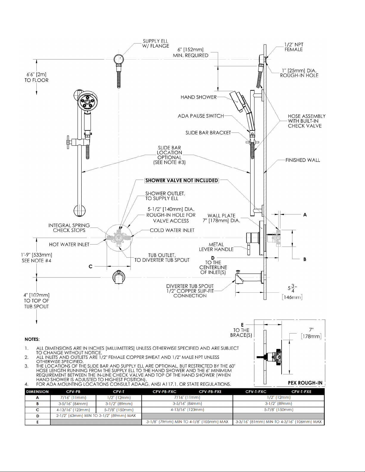
ROUGH-IN
SPEAKMAN®
Phone: 800-537-2107 Fax: 800-977-2747
12/10/18 www.speakman.com 92C-SLV-1050-01
Page 4
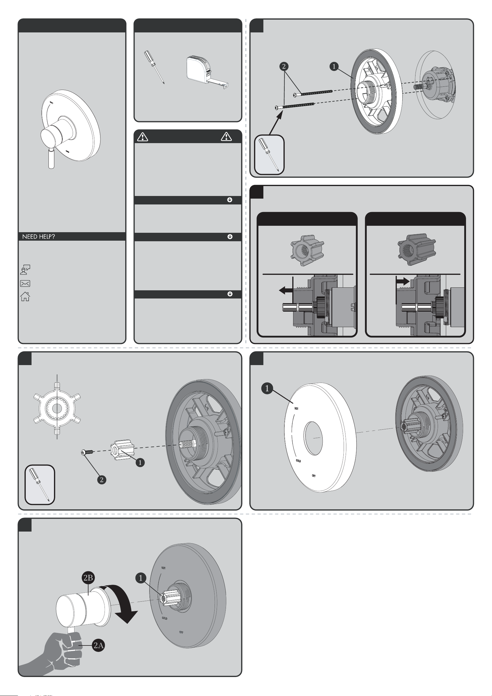
INSTRUCTIONS FOR MODELS
92-CPT-1001-01
For additional assistance or service please contact:
SPEAKMAN
®
800-537-2107
www.speakman.com
CPT-1001
TOOLS AND SUPPLIES
Phillips
Screwdriver
Measuring
Tape
Warranty information can be found at:
www.speakman.com
WARRANTY
MAINTENANCE
Cover your drain to prevent loss of parts.
SAFETY TIPS
IMPORTANT
• Be sure to read instructions thoroughly before
beginning installation.
• Do not over-tighten any connections or damage
may occur.
• Be sure to have properly adjusted the Temperature
Limiting Stop (TLS) as per the Valve Installation
Instructions before installing Valve Trim.
Your new Speakman Product is designed for years of
trouble-free performance. Keep it looking new by
cleaning it periodically with a soft cloth. The use of harsh
chemicals and abrasives on any of the Speakman custom
finish products may damage the finish and void the
product warranty. Please be sure to only use approved
cleaners. Please contact Speakman for any clarification
of acceptable cleaners.
1
Clean wall surface. Place Mounting Base (1) onto the valve, align mounting holes, and secure with
supplied screws (2).
2
Verify the position of the Spindle within the Mounting Plate, as shown below. If the end of the
Spindle extends beyond the Mounting Plate, then use the Shallow Mount Adapter. If the end of the
Spindle is flush to, or is within the Mounting Plate, then use the Deep Mount Adapter.
FOR SHALLOW MOUNT APPLICATION
FOR DEEP MOUNT APPLICATION
3
Confirm that Valve is in the “Off” position. Place appropriate Connector (1) on to the Spindle of the
Valve, making sure to orient the Connector so that one set of Splines are in a perfectly vertical
position. Secure Connector with 8-32 screw provided (2).
Splines in Vertical Position
4
Place Escutcheon (1) on Mounting Base. Take care to orient the Escutcheon as shown below.
5
Align Handle Assembly with Connector (1) and Escutcheon as shown below. Keep Handle (2A) in a
stationary vertical position and place over Connector (1) and engage the Splines of the Connector
with the Handle Assembly. Keep Handle in the vertical position as you thread Handle Hub (2B) on
to Mounting Base. Tighten until snug.
Page 5
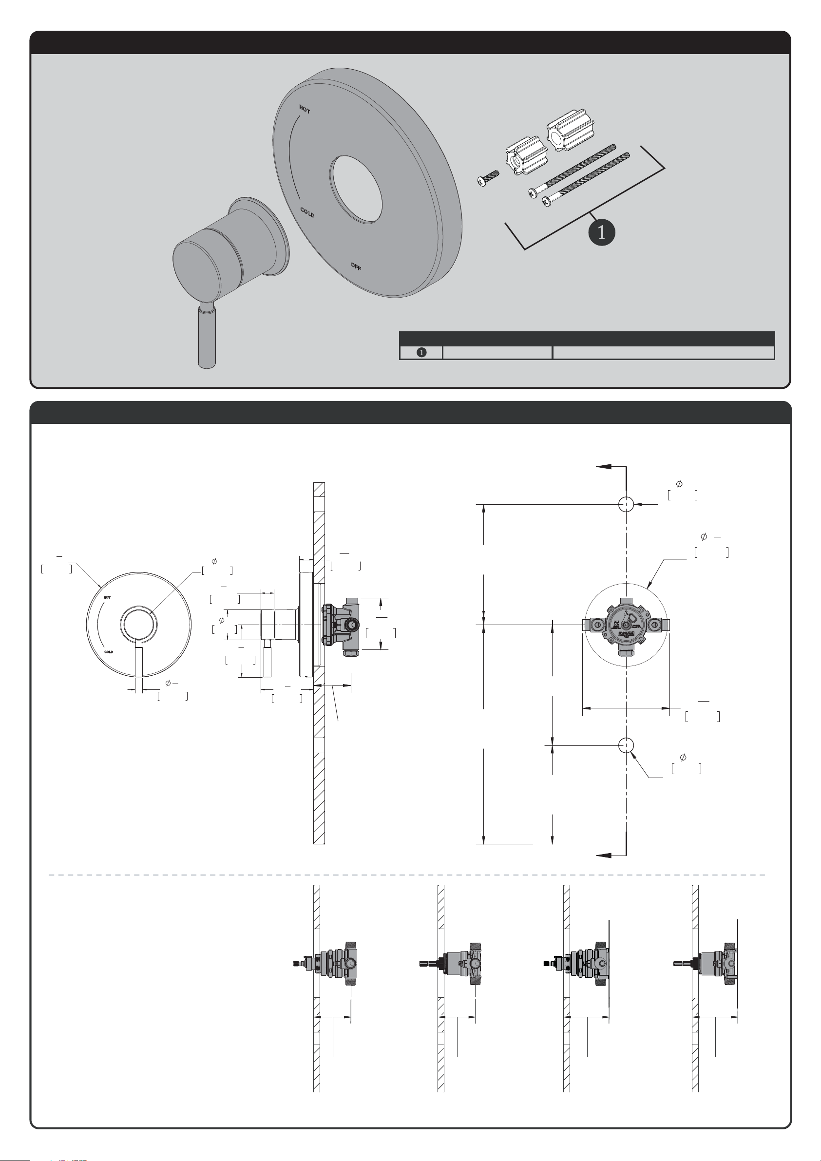
CPT-1001 REPAIR PARTS
SPEAKMAN
®
RPG05-0874 SCREWS AND SPLINE ADAPTERS
ITEM NO. PART NO. DESCRIPTION
CPT-1001 ROUGH-IN DIAGRAM
SPEAKMAN
®
DIMENSIONS SUBJECT TO CHANGE WITHOUT NOTICE.
VALVE MOUNTING IS SHOWN FOR REFERENCE ONLY.
VALVE IS NOT INCLUDED WITH CPT-1001.
1"
25mm
HOLE FOR
SHOWER ARM
5
1
2
"
140mm
HOLE FOR
VAVLE ACCESS
5
13
16
"
147mm
1'-9"
[533mm]
4"
[102mm]
TO TOP OF
TUB LEDGE
4'-6"
[1.4 METERS]
TO FLOOR
(SHOWER INSTALL ONLY)
6'-6"
[2 METERS]
TO FLOOR
1"
25mm
HOLE FOR
TUB SPOUT
A
A
2-1/2" [64mm] MINIMUM
3-1/2" [89mm] MAXIMUM
ROUGH IN DEPTH
3
7
16
"
87mm
SECTION A-A
R3
1
2
"
88.9mm
2"
50.4mm
1
2
"
12.7mm
3
1
2
"
88.4mm
15
16
"
23.6mm
7
8
"
22.6mm
2"
51mm
3
1
2
"
88.8mm
NOTE: TRIM FITS DIFFERENT VALVES. ROUGH-IN
DIMENSIONS PROVIDED FOR REFERENCE ONLY.
2-1/2" MIN
CPV-T CPV-PB CPV-T-PXC
CPV-T-PXE
CPV-PB-PXC
CPV-PB-PXE
[64mm]
3-1/2" MAX
[89mm]
(ADJUSTMENT)
2-1/2" MIN
[64mm]
3-1/2" MAX
[89mm]
(ADJUSTMENT)
3-3/16" MIN
[81mm]
4-3/16" MAX
[106mm]
(ADJUSTMENT)
3-1/8" MIN
[80mm]
4-1/8" MAX
[105mm]
(ADJUSTMENT)
Page 6
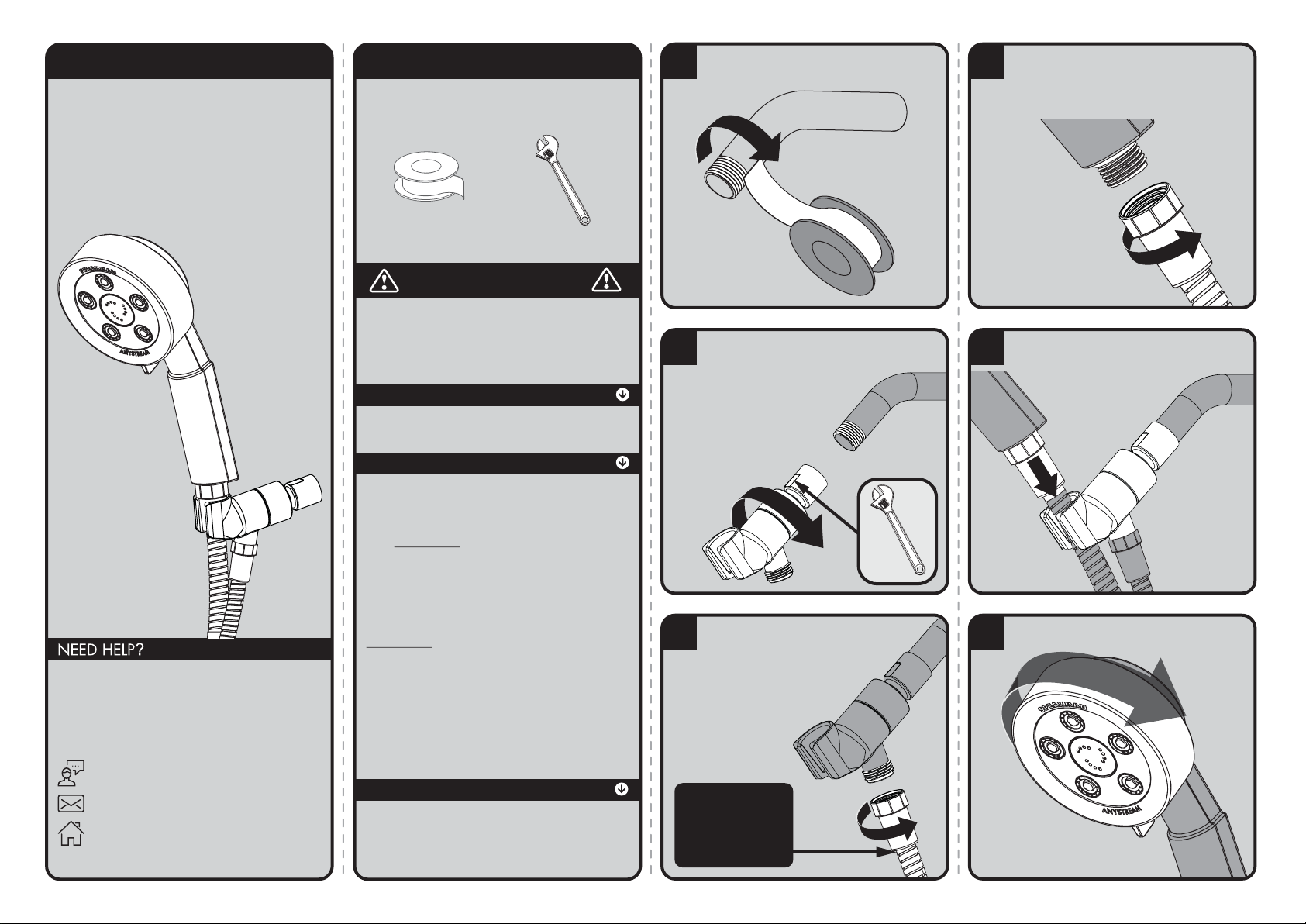
INSTRUCTIONS FOR MODELS
92-VS-3010-02
For additional assistance or service please contact:
SPEAKMAN
®
Company
400 Anchor Mill Road
New Castle, DE 19720
800-537-2107
www.speakman.com
VS-3010
VS-3010-E2
VS-3010-E175
TOOLS AND SUPPLIES
1
Apply Thread Seal Tape to the outlet side
of shower arm in a clockwise direction.
2
Thread Bracket onto shower arm by
turning it in a clockwise direction.
Tighten with adjustable wrench.
3
Ensure Hose Washer is inserted inside
connector to avoid leaks.Thread Hose
End with Label to the outlet port of
Bracket. Hand tighten.
WATER WILL NOT FLOW
THROUGH THE HOSE IF
THE WRONG SIDE IS
CONNECTED.
NOTE: Label around
hose shows this end
assembles to water
supply. Remove label
before installation.
4
Ensure Hose Washer is inserted inside
connector to avoid leaks. Thread
remaining end of Hose to base of Hand
Shower. Hand tighten.
5
Place Hand Shower into Bracket. Turn on
water supplies and check for leaks.
6
Rotate Spray Face to change Spray Settings.
Thread Seal
Tape
(included)
Adjustable
Wrench
IMPORTANT
Be sure to read instructions thoroughly before
beginning installation. Do not overtighten any
connections or damage may occur. This hand shower
has an optimal operating range of 20-80 psi.
SAFETY TIPS
Cover your drain to prevent loss of parts.
MAINTENANCE
Periodic cleaning using a mild soap and warm water
will help keep your Hand Shower’s appearance in its
original condition.
For best results, dry immediately with a soft, clean
cloth. DO NOT USE harsh and/or abrasive cleaners.
On CHROME PLATED HAND SHOWERS, a two (2)
part white vinegar, one (1) part water solution can be
used to break down excessive mineral deposits on the
sprays. Let the hand shower soak in the solution for
about ½ hour then rinse thoroughly. Brush off any
remaining mineral deposits if necessary.
DO NOT USE the vinegar/water treatment on any
finish other than Chrome.
To reduce mineral build-up, turn the handle to FLOOD
position to let the water drain out after every use.
WARRANTY
Additional warranty information can be found at:
www.speakman.com
Page 7
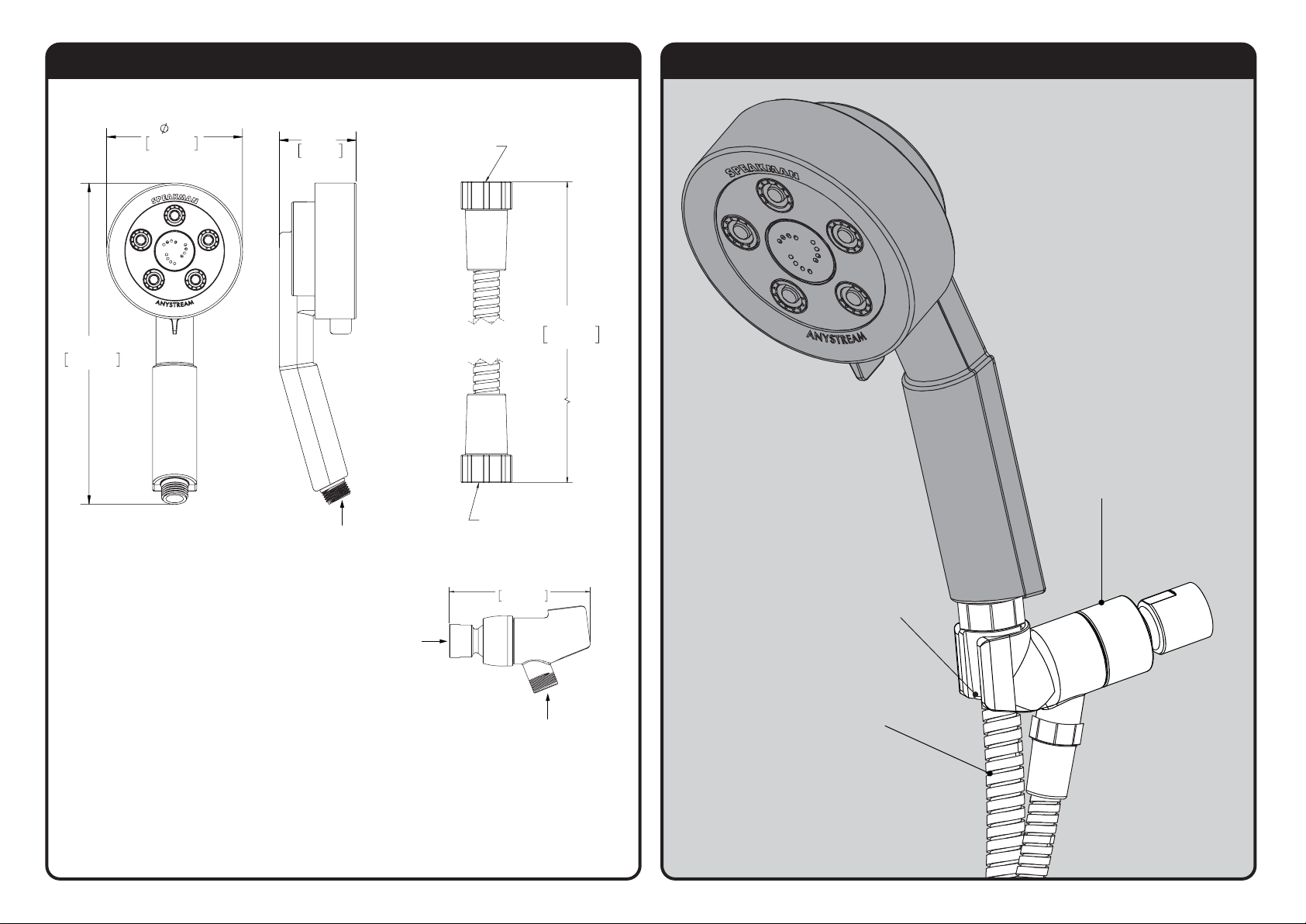
ROUGH IN DIMENSIONS
Model: VS-3010-E175
Max. Flow Rate: 1.75 gpm (6.6 L/min)
Min. Flow Rate: 1.3 gpm (4.9 L/min) @ 45psi
FOR USE WITH AUTOMATIC COMPENSATING VALVES RATED
AT 5.7 L/MIN (1.5 GPM) OR LESS.
Model: VS-3010
Max. Flow Rate: 2.5 gpm (9.5L/min)
Min. Flow Rate: 2.0 gpm (7.6 L/min) @ 45psi
FOR USE WITH AUTOMATIC COMPENSATING VALVES RATED
AT 7.6 L/MIN (2.0 GPM) OR LESS.
Model: VS-3010-E2
Max. Flow Rate: 2.0 gpm (7.6 L/min)
Min. Flow Rate: 1.5 gpm (5.7 L/min) @ 45psi
FOR USE WITH AUTOMATIC COMPENSATING VALVES RATED
AT 6.6 L/MIN (1.75 GPM) OR LESS.
4”
9-1/2”
240mm
102mm
1/2-14 NPSM
THREADED
INLET
2-1/4”
58mm
4"
102mm
1/2-14 NPT
THREADED
INLET
1/2-14 NPSM
THREADED
OUTLET
61"
165mm
1/2"-14 NPSM FEMALE
THREADED OUTLET
1/2"-14 NPSM FEMALE
THREADED INLET
MARKED
"ATTACH THIS CHECK
VALVE END TO THE
WATER SUPPLY"
REPAIR PARTS
VS-130-XX
BRACKET ASSEMBLY
* XX = FINISH
RPG45-41791
HOSE WASHER GROUP
VS-158-XX
HOSE ASSEMBLY
Page 8
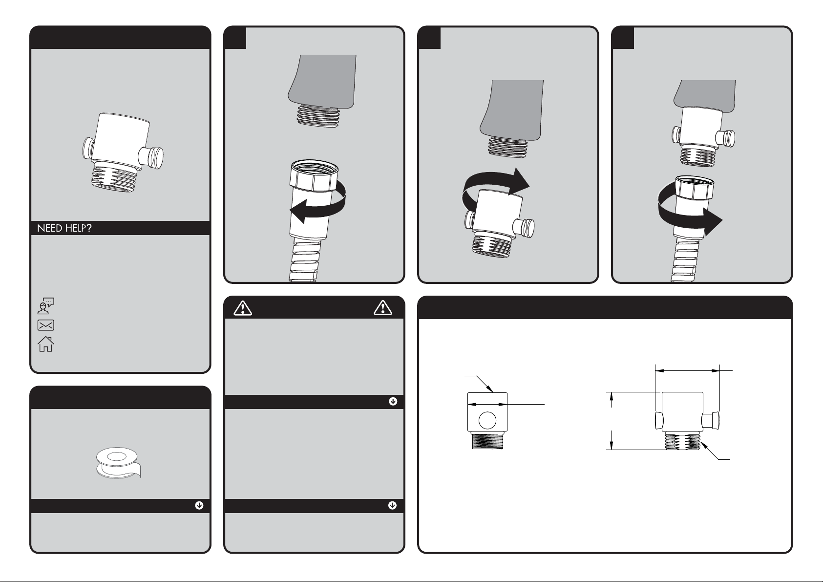
INSTRUCTIONS FOR MODELS
VS-156
IMPORTANT
TOOLS AND SUPPLIES
1
Turn off water supply. Remove hose from
existing Hand Held Shower Head.
2
Insert proper washer to ensure no leaking occurs
from Volume Control to Hand Held Shower
connections (multiple washers are included for
various types of installations). Screw on Volume
Control to Hand Held Shower and hand tighten.
3
Thread hose onto inlet port of Volume Control
and hand tighten. Turn on water supply and
check for leaks. If leaks are present, disassemble
all connections and apply Telon Tape.
Re-assemble.
VS-156 ROUGH-IN DIAGRAM
SPEAKMAN
®
DIMENSIONS SUBJECT TO CHANGE WITHOUT NOTICE.
1.36”
(34.5mm)
1.52”
(38.7mm)
1/2” NPSM
MALE
THREAD
1/2” NPSM
FEMALE
THREAD
.96”
(24.4mm)
For additional assistance or service please contact:
SPEAKMAN
400 Anchor Mill Road
New Castle, DE 19720
800-537-2107
www.speakman.com
92-VS-156-02
®
Company
Thread Seal
Tape
SAFETY TIPS
Cover your drain to prevent loss of parts.
• Do not over-tighten any connections or damage
may occur.
• Be sure to read instructions thoroughly before
beginning installation.
MAINTENANCE
Your new Speakman Product is designed for years
of trouble-free performance. Keep it looking new by
cleaning it periodically with a soft cloth. The use of
harsh chemicals and abrasives on any of the
Speakman custom finish products may damage the
finish and void the product warranty. Please be sure
to only use approved cleaners. Please contact
Speakman for any clarification of acceptable
cleaners.
WARRANTY
Additional warranty information can be found at:
www.speakman.com
Page 9

Page 10
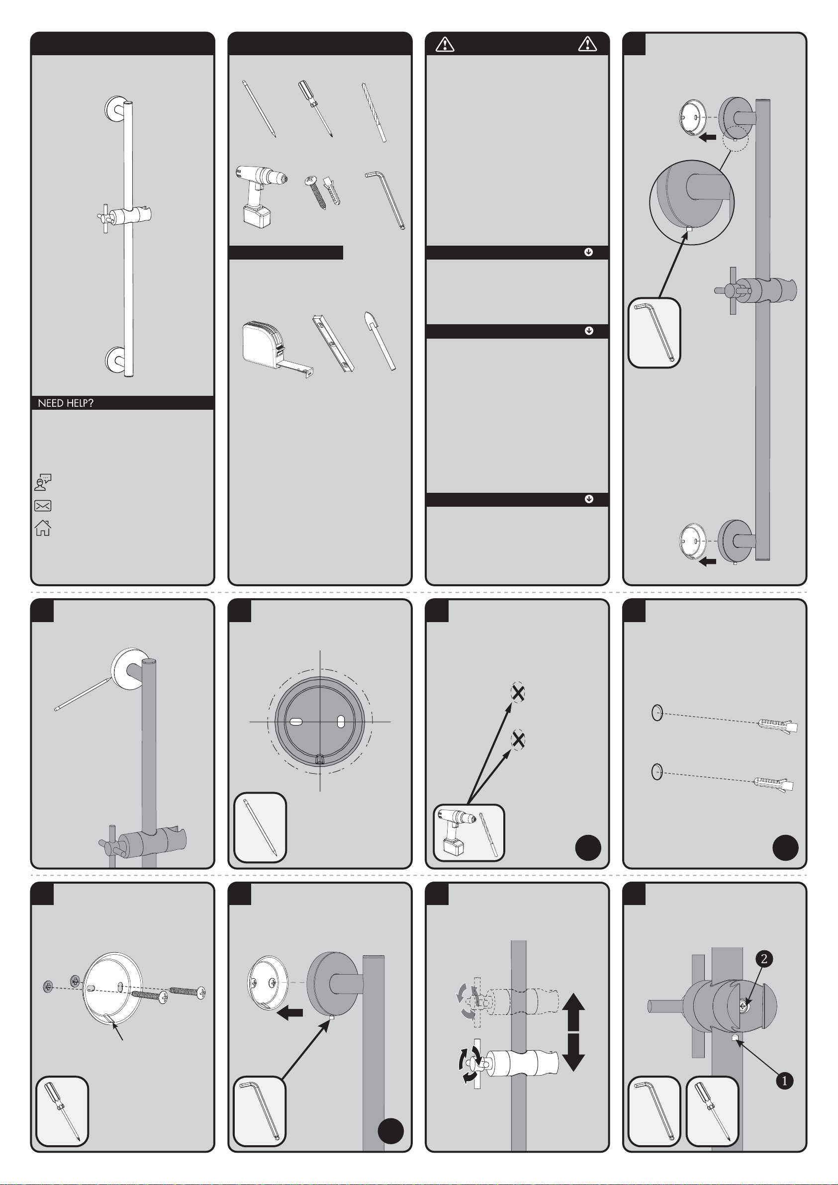
INSTRUCTIONS FOR MODELS
92-SA-1002-02
For additional assistance or service please contact:
SPEAKMAN
®
Company
400 Anchor Mill Road
New Castle, DE 19720
800-537-2107
www.speakman.com
SA-1002
HELPFUL TOOLS & SUPPLIES:
TOOLS AND SUPPLIES
Level
Measuring
Tape
Phillips
Screwdriver
Pencil
Drill
Drill Bit
1/4”
Tile Drill Bit
1/4”
Mounting Hardware
(included)
Hex Key
Wrench
Additional warranty information can be found at:
www.speakman.com
WARRANTY
MAINTENANCE
• Cover your drain to prevent loss of parts. Be sure
to follow all tool manufacturers safety guidelines.
• Use caution when drilling into walls to avoid
electrical and plumbing lines hidden within
the wall.
SAFETY TIPS
IMPORTANT
• Do not over-tighten any connections or damage
may occur.
• Be sure to read instructions thoroughly before
beginning installation.
• This item is NOT designed for use as a grab bar.
Do not mount in locations where product is likely
to be used as a grab bar.
Your new Speakman Product is designed for years of
1
Loosen Set Screws with supplied Allen Wrench,
and remove Mounting Brackets from both ends
of Slide Bar assembly.
2
Place Slide Bar Assembly on to wall in the
desired mounting position. Take care that the
Slide Bar is oriented in a vertical position. Using
a pencil, lightly trace outline of end brackets on
to wall.
3
Center Mounting Bracket within traced outline.
Mark the 2 locations with a pencil.
4
Drill 1/4” hole in marked locations. If drilling
into tile, be sure to use a drill bit designated for
tile. If mounting directly into stud or wood wall,
secure lower end bracket to wall with mounting
screws withouth drilling holes.
Ø 1/4”
X4
5
Push the Plastic Anchors (x4) into the drilled
holes. Ensure the plastic anchors are flush with
the wall. (Note: Plastic Anchors provided may
not be suitable for all types of wall construction,
seek professional help if in doubt).
X4
6
Secure Mounting Plate with the Mounting Screws
provided. Ensure Recess Area of Mounting Plate
is aligned vertically as shown below.
RECESS AREA
7
Install Slide Bar assembly over Mounting
Brackets, and secure with Set Screws using
supplied Allen Wrench.
X2
8
Orient the Hand Held Shower Bracket to your
desired position. Adjustments are made by
rotating the Cross Handle counter-clockwise to
release the position, and clockwise to lock into
the desired position.
9
Note: If the Hand Shower Holder no longer
holds position, Loosen the Set Screw (1) from
underneath the Bracket using the supplied Allen
Key. Tighten the Screw (2) in the Shower Holder
using a Philips Head Screwdriver. Then,
re-tighten the Set Screw (1) from below.
trouble-free performance. Keep it looking new by
cleaning it periodically with a soft cloth. The use of harsh
chemicals and abrasives on any of the Speakman custom
finish products may damage the finish and void the
product warranty. Please be sure to only use approved
cleaners. Please contact Speakman for any clarification
of acceptable cleaners.
Page 11
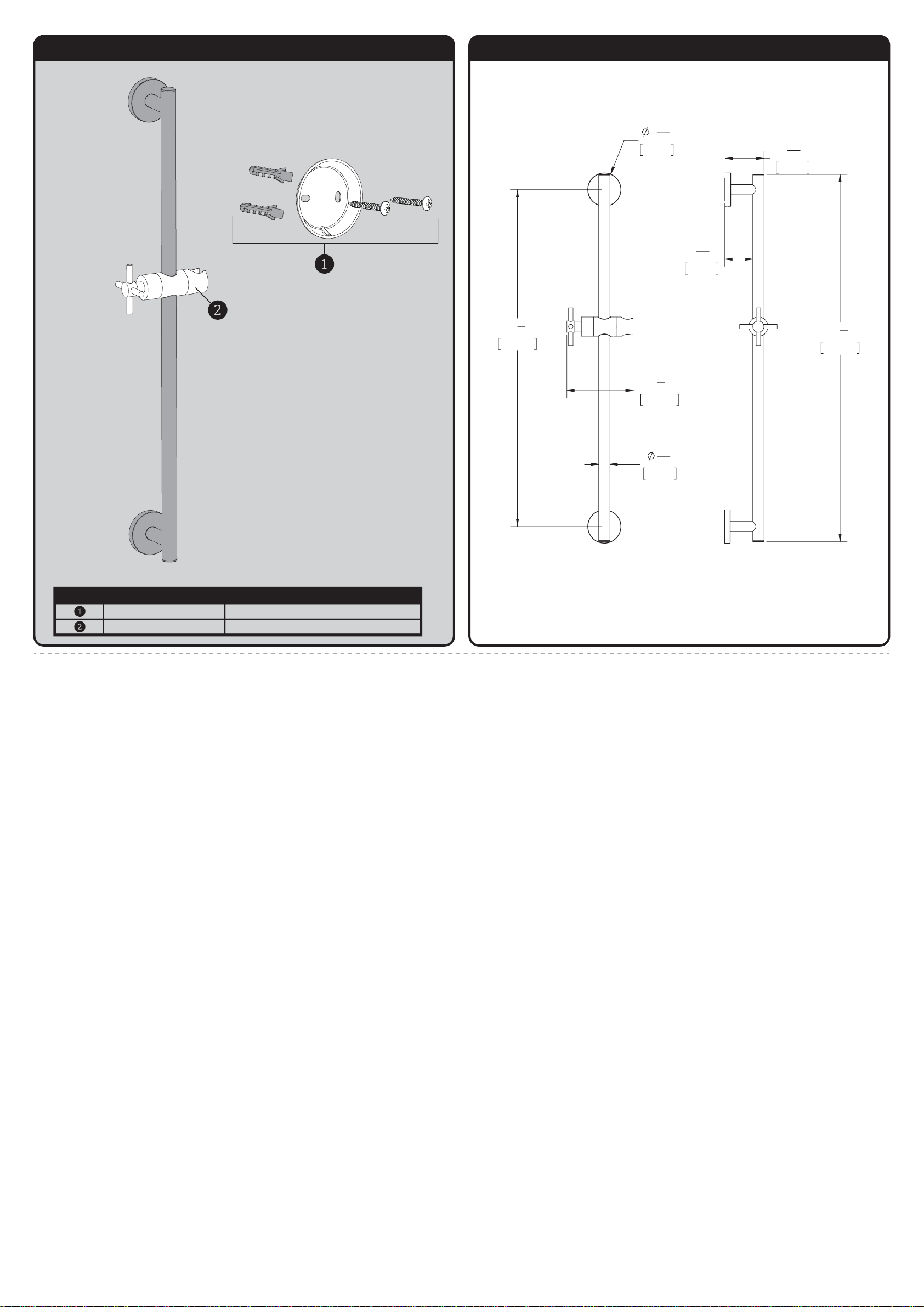
SA-1002 REPAIR PARTS
SPEAKMAN
®
RPG05-0886 MOUNTING HARDWARE
RPG56-0037-XX (XX=FINISH) HAND SHOWER HOLDER
ITEM NO. PART NO. DESCRIPTION
SA-1002 ROUGH-IN DIAGRAM
SPEAKMAN
®
DIMENSIONS SUBJECT TO CHANGE WITHOUT NOTICE.
2
5
16
"
60mm
4
5
8
"
118mm
13
16
"
20mm
23
5
8
"
600mm
2
11
16
"
69mm
1
15
16
"
50mm
25
3
4
"
654mm
Page 12
INSTRUCTIONS FOR MODELS
TOOLS AND SUPPLIES
1
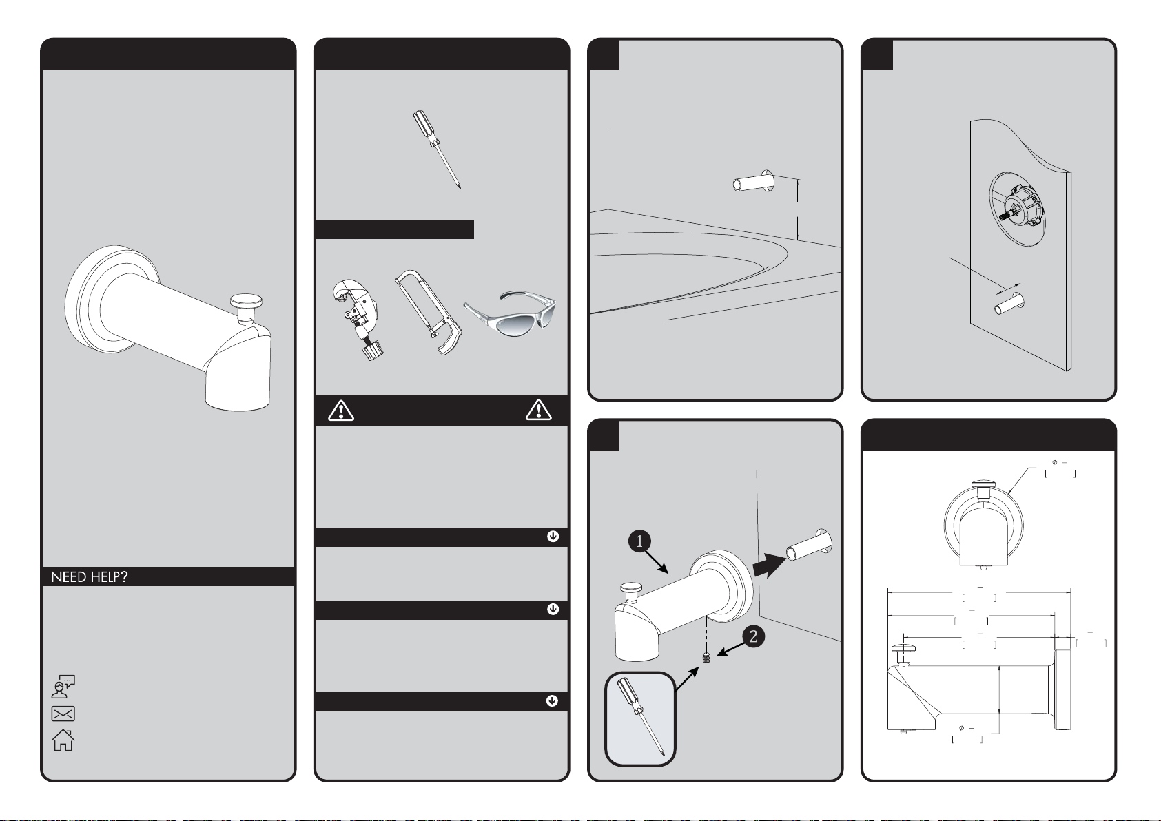
The minimum distance between the center of the
tub spout and the rim of the tub should be no
less than 4".
4'' Minimum
2
The stub out for the 1/2" pipe should extend a
minimum of 1.75" from the wall, but not to
exceed 4" from wall. Remove all burs and sharp
edges from the stub out 1/2" pipe.
1.75'' - 4.0''
MIN MAX
3
Slide Spout (1) over exposed stub out pipe until
flush to wall. Center the Spout (1) on the wall
and tighten Set Screw (2) from underneath with
a Phillips Screwdriver.
ROUGH-IN DIAGRAM
DIMENSIONS SUBJECT TO CHANGE WITHOUT NOTICE.
S-1558
Phillips
Screwdriver
HELPFUL TOOLS & SUPPLIES:
For additional assistance or service please contact:
SPEAKMAN
®
Company
400 Anchor Mill Road
New Castle, DE 19720
800-537-2107
www.speakman.com
Tubin g
Cutter
Hacksaw Safety
Glasses
IMPORTANT
• Do not over-tighten any connections or damage
may occur.
• Be sure to read instructions thoroughly before
beginning installation.
SAFETY TIPS
Cover your drain to prevent loss of parts. Be sure to
wear eye protection while cutting pipe.
MAINTENANCE
Your new Speakman product is designed for years
of trouble-free performance. Keep it looking new by
cleaning it periodically with a soft cloth. Avoid
abrasive cleaners, steel wool, and harsh chemicals
as these will dull the finish and void your warranty.
WARRANTY
Additional warranty information can be found at:
www.speakman.com
146.05mm
5
133.34mm
120.64mm
1
38.10mm
1
"
2
2
63.50mm
3
"
5
4
1
"
4
3
"
4
4
1
"
2
12.71mm
1
"
2
92-S-1558-03
 Loading...