

Page 1

®
SPEAKMAN
SLV-5480-ADA
Installation, Operation & Maintenance Instructions
SENTINELPRO™ COMBINATION SERIES
DESCRIPTION
Speakman SentinelPro™ Combination, SLV-5480-ADA includes: Trim with integral Volume Control Handle
(CPT-5401), Shower Arm with Wall Flange (S-2500), Hand Shower with Flow Control (VS-100-PC), Shower
Arm Bracket, 60in Shower Hose with Built-in Vacuum Breaker, and 24in ADA Combination Grab/Slide Bar
(VS-153-ADA). This combination does not include the Shower Valve.
This combination should be installed with one of the following
Speakman SentinelPro™ Thermostatic/Pressure Balance Diverter Shower Valves
CPV-TP-DV: Thermostatic/Pressure Balance Diverter Shower Valve
Sweat & Thread Connections
CPV-TP-DV-PXC: Thermostatic/Pressure Balance Diverter Shower Valve
PEX F1807 Crimp Inlet Connections
CPV-TP-DV-PXE: Thermostatic/Pressure Balance Shower Valve
PEX F1960 Cold-Expansion Inlet Connections
SPECIFICATIONS
CPT-5401 T/P DIVERTER VALVE TRIM:
FINISH: Polished Chrome
COMPLIANCE: ASME A112.18.1 / CSA B125.1 Standard
S-2500 SHOWER ARM WITH WALL FLANGE:
CONNECTIONS: ½” NPT Male Inlet & Outlet
FINISH: Polished Chrome
VS-1001-ADA-PC HANDICAP SHOWER COMBINATION:
VS-100-PC HAND SHOWER WITH FLOW CONTROL:
CONNECTIONS: ½” NPSM Male Inlet
FLOW RATE: 2.5 gpm (9.5 L/min)
FINISH: Polished Chrome
COMPLIANCE: ASME A112.18.1 / CSA B125.1 Standard
SHOWER ARM BRACKET:
CONNECTIONS: ½” NPSM Male Inlet; ½” NPSM Female Outlet
FINISH: Polished Chrome
60in SHOWER HOSE (w/ BUILT-IN VACUUM BREAKER):
CONNECTIONS: ½” NPSM Female Inlet & Outlet
FINISH: Polished Chrome
VS-153-ADA 24in ADA COMBINATION GRAB/SLIDE BAR:
FINISH: Polished Chrome
COMPLIANCE: Meets 250 lbs pull test for Grab Bars per ANSI Standard;
Meets requirements of ADA Lever Handle for adjusting Slide Bar
SPEAKMAN®
400 Anchor Mill Rd. New Castle, DE 19720 Phone: 800-537-2107 Fax: 800-977-2747
07/31/18 www.speakman.com 92C-SLV-5480-ADA-01
Page 2
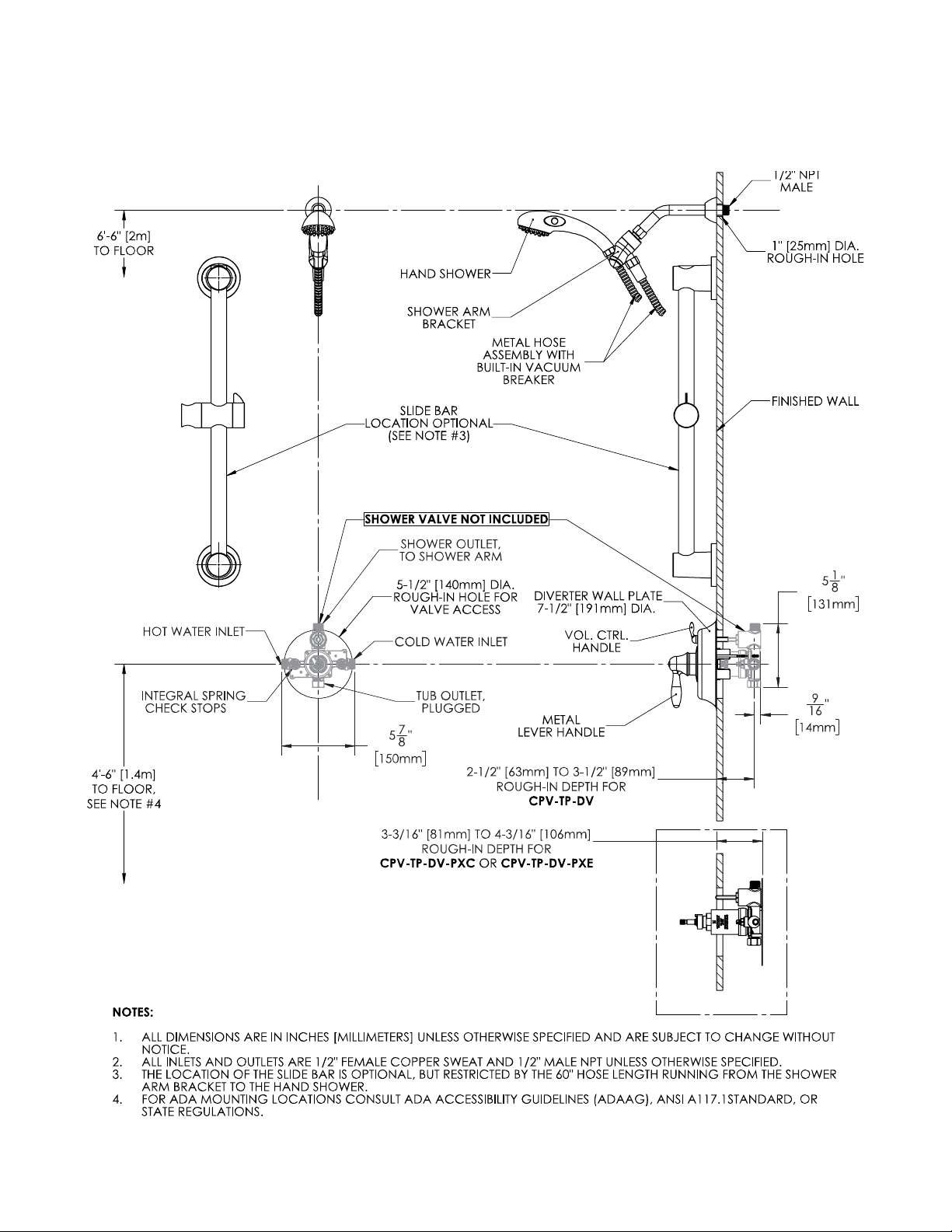
INSTRUCTIONS
See individual products for installation of the components and warranty information.
ROUGH-IN
SPEAKMAN®
400 Anchor Mill Rd. New Castle, DE 19720 Phone: 800-537-2107 Fax: 800-977-2747
07/31/18 www.speakman.com 92C-SLV-5480-ADA-01
Page 3
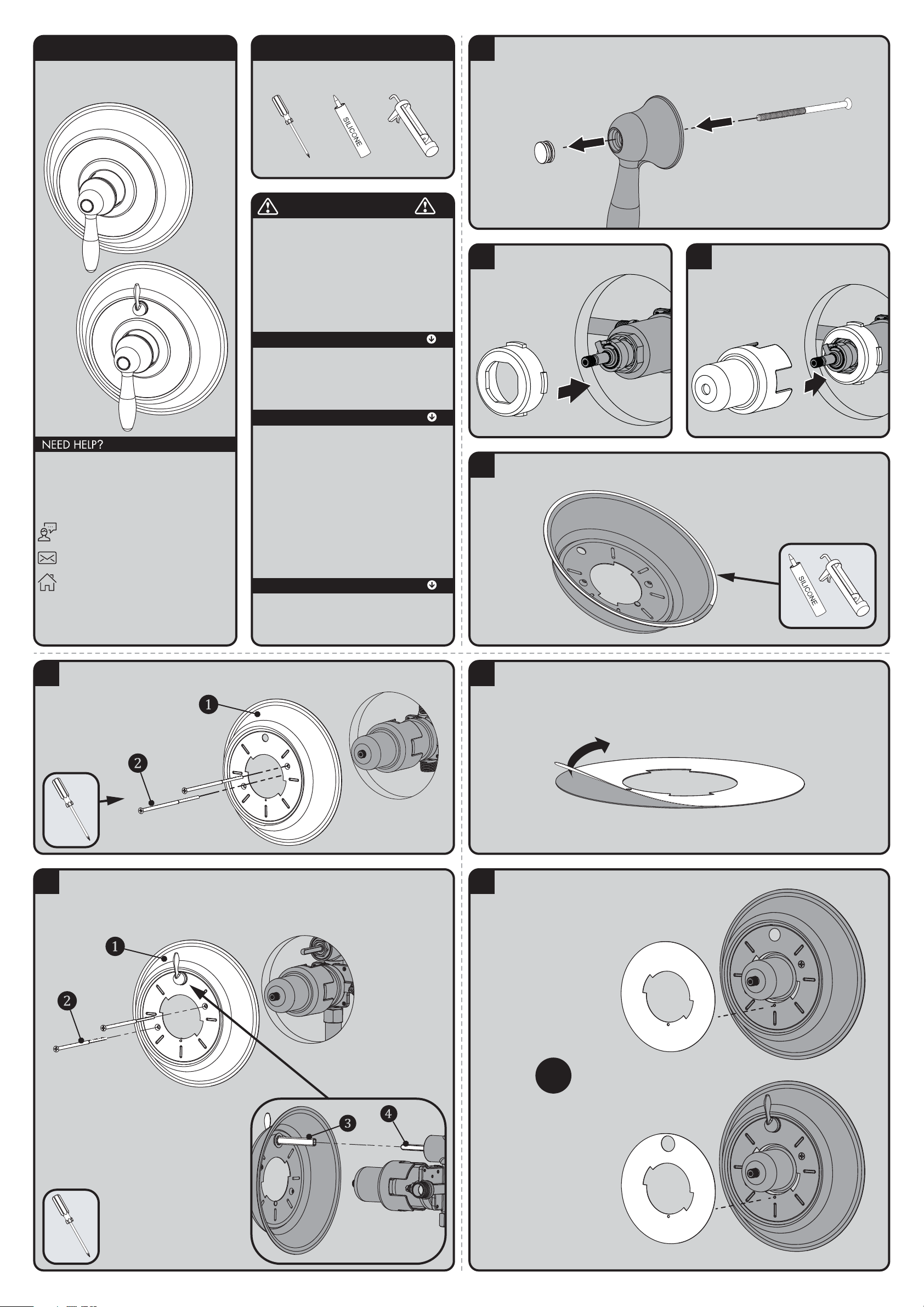
INSTRUCTIONS FOR MODELS
92-CPT-5001-01
For additional assistance or service please contact:
SPEAKMAN
®
Company
400 Anchor Mill Road
New Castle, DE 19720
800-537-2107
www.speakman.com
CPT-5001 / CPT-5401
TOOLS AND SUPPLIES
Phillips
Screwdriver
Silicone Caulk Gun
Additional warranty information can be found at:
www.speakman.com
WARRANTY
MAINTENANCE
Cover your drain to prevent loss of parts. Be sure to
wear eye protection while cutting pipe.
SAFETY TIPS
IMPORTANT
• Be sure to read instructions thoroughly before
beginning installation.
• Do not over-tighten any connections or damage
may occur.
• This valve has an operating range of 20-80 psi.
Your new Speakman Product is designed for years of
trouble-free performance. Keep it looking new by
cleaning it periodically with a soft cloth. The use of harsh
chemicals and abrasives on any of the Speakman custom
finish products may damage the finish and void the
product warranty. Please be sure to only use approved
cleaners. Please contact Speakman for any clarification
of acceptable cleaners.
1
Remove the Handle Button Screw by inserting one of the included Mounting Screws thru the hole in the Handle.
2
Insert the T/P Rubber Sleeve with Tabs over
Valve Bonnet.
3
Be sure to have properly adjusted the Temperature
Limiting Stop (TLS) as per the Valve Installation
Instructions before installing
Valve Trim. Slide Trim Sleeve
over the Rubber Sleeve.
Ensure the tabs are
properly seated within
the grooves of the
Trim Sleeve.
4
Clean wall surface. Orient Wall Plate as shown below. Apply clear silicone sealant to the backside outer flat
surface of the Wall Plate, while leaving a small area open at the bottom. This will allow for any moisture to drain.
5A
FOR CPT-5001 - Align the Wall Plate (1) as shown below. Secure to Valve with the included Mounting Screws
(2). Take care to not over tighten Mounting Screws. Remove excess sealant after securing Wall Plate to wall.
5B
FOR CPT-5401 - Align the Wall Plate (1) as shown below. Verify the Diverter Valve Stem is in the OFF (vertical)
position. Align the Diverter Drive Tube (3) on the Wall Plate to the Stem (4) of the Diverter Valve. Secure to Valve
with the included Mounting Screws (2). Take care to not over tighten Mounting Screws. Remove excess sealant
after securing Wall Plate to wall.
* VIEW FROM BACK OF WALL PLATE
6
Remove protective film from Trim Index Plate.
7
OR
CPT-5001: Slide Index Plate over
the Trim Sleeve. Align Index Plate
with the small Alignment Pin on the
Wall Plate, and hold Index Plate in
place for the next step.
CPT-5401: Slip the upper hole of
the Index Plate over the Diverter
Handle and then align the large hole
of the Index Plate over the Trim
Sleeve. Align Trim Index Plate with
the small Alignment Pin on the Wall
Plate, and hold Index Plate in place
for the next step.
Page 4
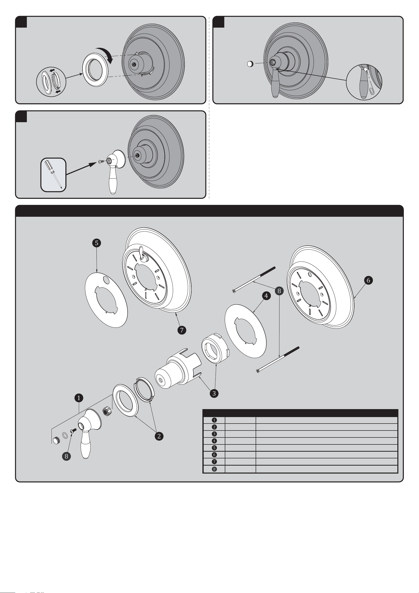
8
Ensure the Rubber Gasket is correctly installed to the Retaining
Ring. Align the Retaining Ring with the slots on the Wall Plate.
Press and Rotate the ring clock-wise until it Locks / Seals in place.
Make sure the seal is secure with the Wall Plate.
9
Temporarily place Handle over splines and adjust the valve to
the OFF position (as per the Valve Instructions). Then, align Handle
vertically as shown below. Secure Handle to Spindle with the
included #8 Screw.
10
Insert Handle Button into the Handle.
* VIEW FROM BACK UNDERSIDE OF HANDLE
If further adjustments need to be made after
the Handle Button is inserted, there is an
access hole at the back side of the handle.
Use a paper clip to push the Button back out.
CPT-5001 / CPT-5401 REPAIR PARTS
SPEAKMAN
®
ITEM NO. PART NO. DESCRIPTION
RPG04-0443 HANDLE ASSEMBL Y
RPG05-1111 RETAINING RING WITH SEAL
RPG05-1110 TRIM SLEEVE AND RUBBER SLEEVE
RPG41-0286 INDEX PLATE
RPG10-0120 WALL PLATE
RPG10-0121 WALL PLATE WITH DIVERTER
RPG10-0119 MOU NTIN G HARDWARE (A LL SCRE WS)
RPG41-0286-DV DIVERTER MODEL INDEX PLATE
Page 5
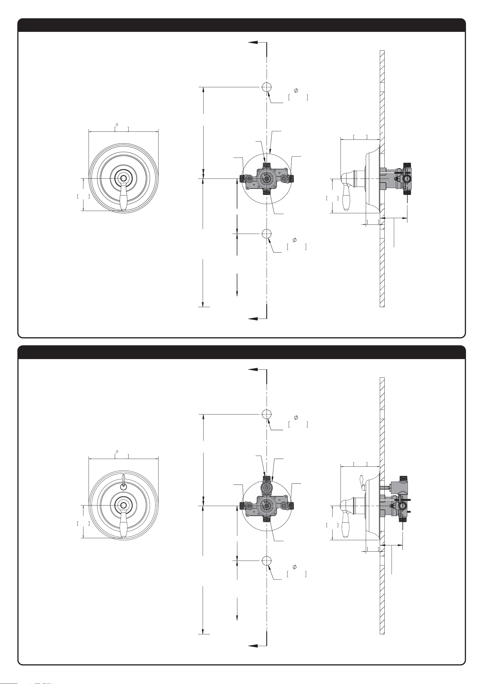
CPT-5001 ROUGH-IN DIAGRAM
SPEAKMAN
®
DIMENSIONS SUBJECT TO CHANGE WITHOUT NOTICE.
7.50in
CPT-5401 ROUGH-IN DIAGRAM
SPEAKMAN
®
DIMENSIONS SUBJECT TO CHANGE WITHOUT NOTICE.
191mm
6'-6" [2 METERS]
TO FLOOR
1/2" NPT MALE
1/2" SWEAT
CONNECTION
A
1/2" NPT MALE
1/2" SWEAT
CONNECTION
1"
25mm
HOLE FOR
SHOWER ARM
5-1/2" (140MM) DIA.
HOLE FOR
VALVE ACCESS
1/2" NPT MALE
1/2" SWEAT
CONNECTION
4.31in
110mm
3.50in
89mm
VALVE MOUNTING IS SHOWN FOR REFERENCE ONLY.
VALVE IS NOT INCLUDED WITH CPT-5000
1'-9" [533mm]
4’-6" [1.4 METERS]
TO FLOOR
(SHOWER
INSTALLATION
ONLY)
4" [102mm]
TO TOP OF
TUB LEDGE
A
1/2" NPT MALE
1/2" SWEAT
CONNECTION
1"
25mm
HOLE FOR
TUB SPOUT
3.75in
95mm
1.53in
39mm
2-1/2" MIN
[64mm]
3-1/2" MAX
[89mm]
(ADJUSTMENT)
3.50in
89mm
7.50in
191mm
6'-6" [2 METERS]
TO FLOOR
1/2" NPT MALE
1/2" SWEAT
CONNECTION
A
1/2" NPT MALE
1/2" SWEAT
CONNECTION
1"
25mm
HOLE FOR
SHOWER ARM
5-1/2" (140MM) DIA.
HOLE FOR
VALVE ACCESS
1/2" NPT MALE
1/2" SWEAT
CONNECTION
3.75in
95mm
4.31in
110mm
VALVE MOUNTING IS SHOWN FOR REFERENCE ONLY.
VALVE IS NOT INCLUDED WITH CPT-5400
1'-9" [533mm]
4’-6" [1.4 METERS]
TO FLOOR
(SHOWER
INSTALLATION
ONLY)
4" [102mm]
TO TOP OF
TUB LEDGE
A
1/2" NPT MALE
1/2" SWEAT
CONNECTION
1"
25mm
HOLE FOR
TUB SPOUT
1.53in
39mm
2-1/2" MIN
[64mm]
3-1/2" MAX
[89mm]
(ADJUSTMENT)
Page 6
INSTRUCTIONS FOR MODELS
92-S-2500-R5
For additional assistance or service please contact:
SPEAKMAN
®
Company
400 Anchor Mill Road
New Castle, DE 19720
800-537-2107
www.speakman.com
S-2500
TOOLS AND SUPPLIES
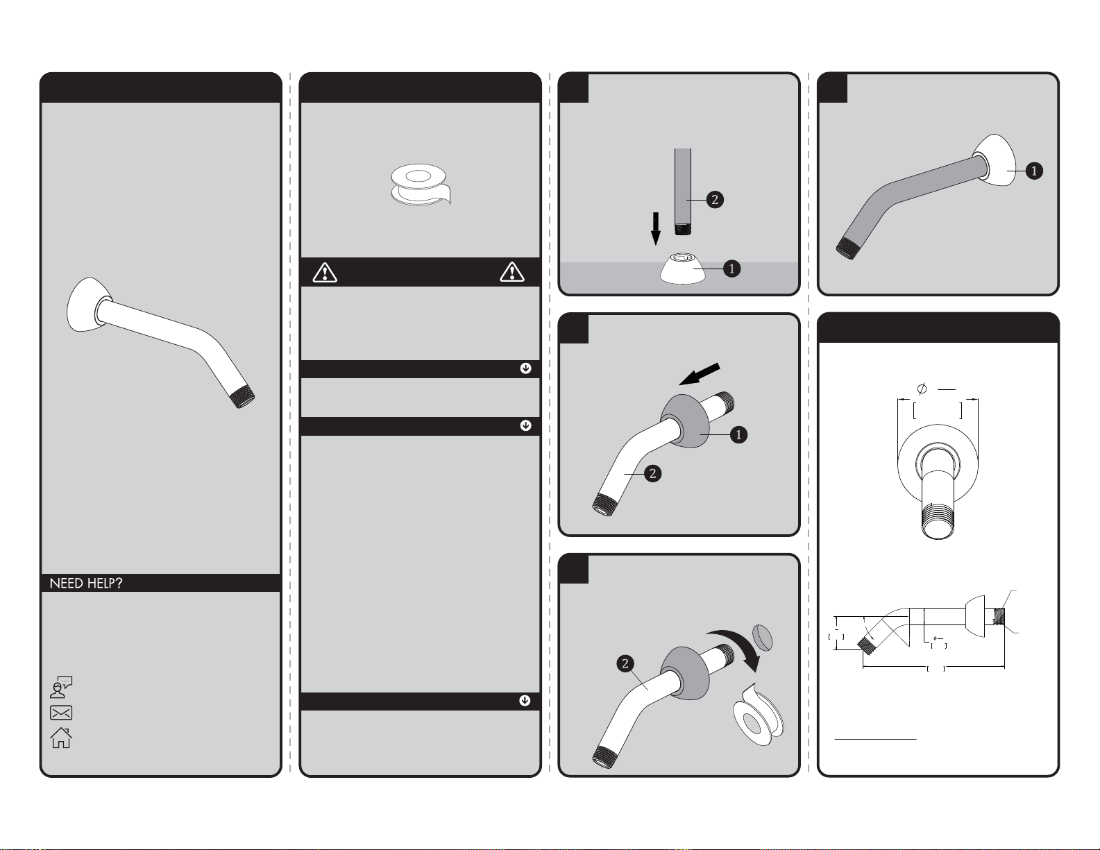
1
Place the Escutcheon Plate (1) on a flat
surface. Push the long end of the Shower
Arm (2) down into the plate. This will
help the teeth of the plate slide over the
arm easier.
2
Once the Escutcheon Plate (1) is on the
shower arm, slide the plate over the
Shower Arm (2).
3
Apply Teflon Tape to inlet side of Shower
Arm (2). Thread Shower Arm (2) into Female
Pipe Fitting within the wall. Firmly tighten,
and make sure Shower Arm (2) Outlet is
pointing in a downward position.
4
Position Escutcheon Plate (1) flat against wall.
ROUGH IN DIMENSIONS
Specifications:
Supply Inlet: 1/2" NPT MALE
Outlet: 1/2" NPT MALE
2
1
16
"
52mm
13
16
"
21mm
45.00°
7"
178mm
1
5
8
"
42mm
1/2" NPT THREADS
BOTH ENDS
INLET
Thread Seal
Tape
IMPORTANT
Be sure to read instructions thoroughly before
beginning installation. Do not overtighten any
connections or damage may occur.
SAFETY TIPS
Cover your drain to prevent loss of parts.
MAINTENANCE
Your new Shower Arm is designed for years of
trouble-free performance. Keep it looking new by
cleaning it periodically with a soft cloth. Avoid
abrasive cleaners, steel wool and harsh chemicals
as these will dull the finish and void your warranty.
WARRANTY
Additional warranty information can be found at:
www.speakman.com
Page 7

®
SPEAKMAN
VS-2954, VS-1001-ADA-PC
Installation, Maintenance & Operation Instructions
ADA / HANDICAP SHOWER AND BAR
DESCRIPTION
Speakman ADA handicap shower system includes hand held shower (VS-100-PC), 5’ stainless steel hose with
built in vacuum breaker, shower arm bracket, and 24” grab/ slide bar assembly (VS-153-ADA). Connects to
standard shower arm. Shower arm flange (10-0219-PC-P) and 8” shower arm (42-0029-PC) for VS-2954
model only. Chrome handheld shower puts out 2.5 GPM/9.46 LPM to meet ANSI A112.18.1 Standard. ADA
Compliant.
Specifications
INLET SUPPLY:
(VS-1001-ADA-PC) ½” NPT FEMALE
(VS-2954) ½” NPT MALE
FLOW RATE: 2.5 GPM/9.46 LPM, MAX., HAND HELD VARIABLE
SHIPPING WEIGHT:
(VS-1001-ADA-PC) 4.5 LBS.
(VS-2954) 4.9 LBS.
Installation
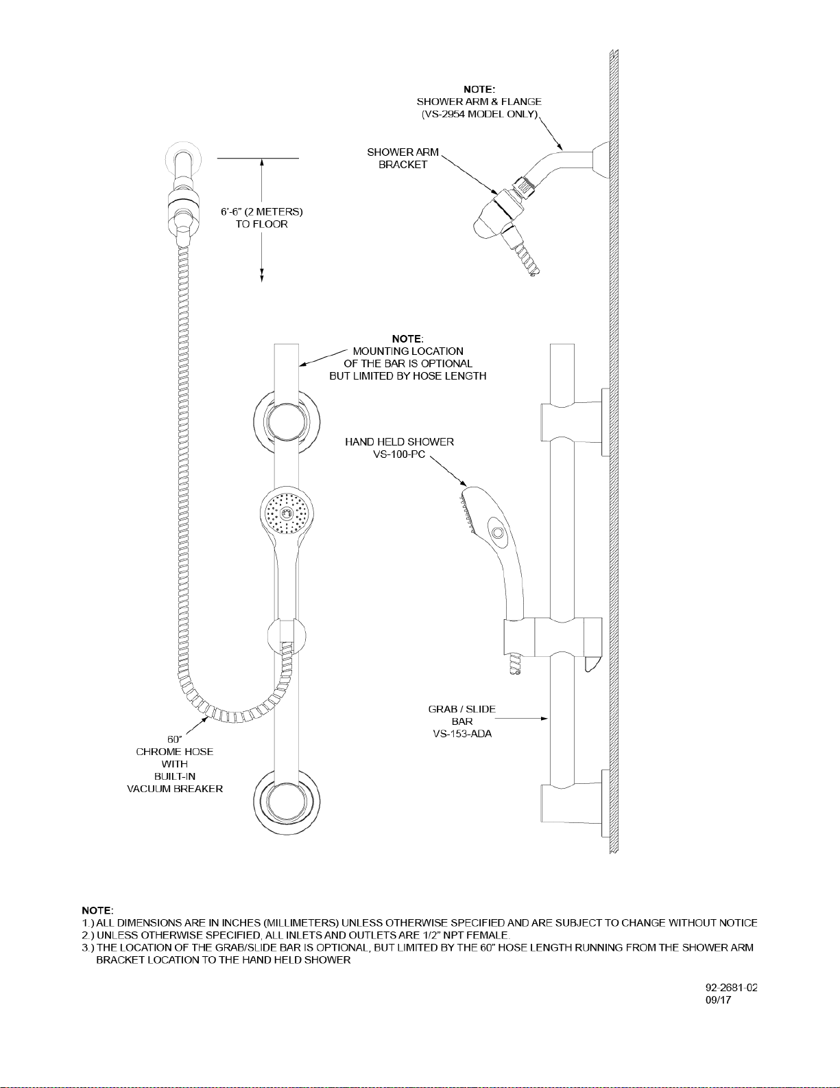
For VS-2954 model only. Slip the wall flange onto the shower arm. Apply thread seal tape clockwise onto the
male threads and screw arm into supply piping behind wall. Wrench tighten. Slip wall flange to wall. Check
for leaks.
Remove (turn counterclockwise) your existing showerhead from the shower arm. Clean the shower arm
threads of any debris and wrap thread seal tape in the clockwise direction around threads. Assemble shower
arm bracket to the shower arm. Hand tighten firmly. Assemble the 5’ hose to the bottom of the shower arm
bracket. Hand tighten firmly. Then attach the other end of the hose to the hand held shower. Make sure the
hose to hand held connection seals on the O-ring at the bottom of the hand held to prevent leaks. When
installing the bar, the location is optional but limited to the length of the hose. For installation of the grab/
slide bar, hold the bar against the wall in the chosen location. Using a pencil, mark the drill hole positions (4 in
total) for the lower and upper mounting brackets. If using as a grab bar, be sure to fasten securely to a wall
stud. (Note: upper mounting bracket height is adjustable) To mount the brackets, use a No. 10 (0.1935
inches/5.5mm) masonry drill bit to make a hole approximately 1-3/8 inches (35 mm) deep. Push the plastic
anchors (4 in total) into the drilled holes, unless your mounting to wall studs, where anchors can be omitted.
(Note: plastic anchors may not be suitable for all types of wall construction, seek professional help if in
doubt) Fix upper mounting bracket and then the lower mounting bracket to the wall using four (4) screws
provided. Push the bracket covers over the mounting brackets while paying close attention to cover
orientation for proper placement.
OPERATION
To operate the handheld shower, push the pause button to one side to bring the flow down to a trickle, then
simply push it to the other side to turn the flow back on full force.
MAINTENANCE
The finish of your SPEAKMAN VERSATILE® hand held shower and all the other components can be cleaned
by using mild soap and warm water. Dry immediately with a soft, clean cloth for best results. The flow control
device limits water flow to 2.5 gallons per minute, and is in the base of the handheld. The small orifice in the
flow regulator, resulting in lower flow and a weaker performance, may become clogged. To clean the flow
regulator, simply remove the hose from the hand shower and clean as necessary.
SPEAKMAN®
400 Anchor Mill Rd. New Castle, DE 19720 Phone: 800-537-2107 Fax: 800-977-2747
9/08/17 www.speakman.com 92-2681-02
Page 8
SPEAKMAN®
400 Anchor Mill Rd. New Castle, DE 19720 Phone: 800-537-2107 Fax: 800-977-2747
9/08/17 www.speakman.com 92-2681-02
Page 9
INSTRUCTIONS FOR MODELS
92-VS-100-PC-04
For additional assistance or service please contact:
SPEAKMAN
®
Company
400 Anchor Mill Road
New Castle, DE 19720
800-537-2107
www.speakman.com
VS-100-PC
VS-100-PC-E2
VS-100-PC-E175
TOOLS AND SUPPLIES
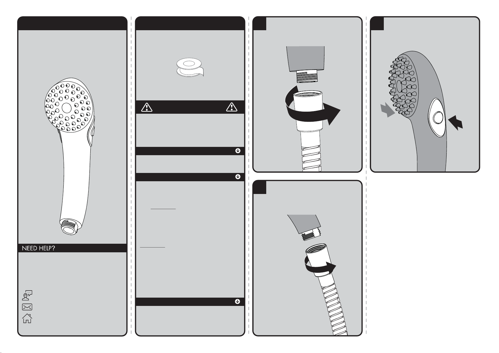
2
Connect remaining end of Hose to inlet
of Hand Shower. Hand tighten. If there
are leaks at the hose connections, look
into using thicker washers to ensure a
tight seal.
1
Connect the correct side of your hose
(not included) to the water supply.
Hand tighten.
3
To pause the flow of water, press the integral
thumb operated pause/trickle button located
on the side of the hand shower. To return the
hand held shower to full flow, press the shuttle
button from the opposite side.
Thread Seal
Tape
(included)
IMPORTANT
Be sure to read instructions thoroughly before
beginning installation. Do not overtighten any
connections or damage may occur. This hand shower
has an optimal operating range of 20-80 psi.
SAFETY TIPS
Cover your drain to prevent loss of parts.
MAINTENANCE
Periodic cleaning using a mild soap and warm water
will help keep your Hand Shower’s appearance in its
original condition.
For best results, dry immediately with a soft, clean
cloth. DO NOT USE harsh and/or abrasive cleaners.
On CHROME PLATED HAND SHOWERS, a two (2)
part white vinegar, one (1) part water solution can be
used to break down excessive mineral deposits on the
sprays. Let the hand shower soak in the solution for
about ½ hour then rinse thoroughly. Brush off any
remaining mineral deposits if necessary.
DO NOT USE the vinegar/water treatment on any
finish other than Chrome.
WARRANTY
Additional warranty information can be found at:
www.speakman.com
Page 10
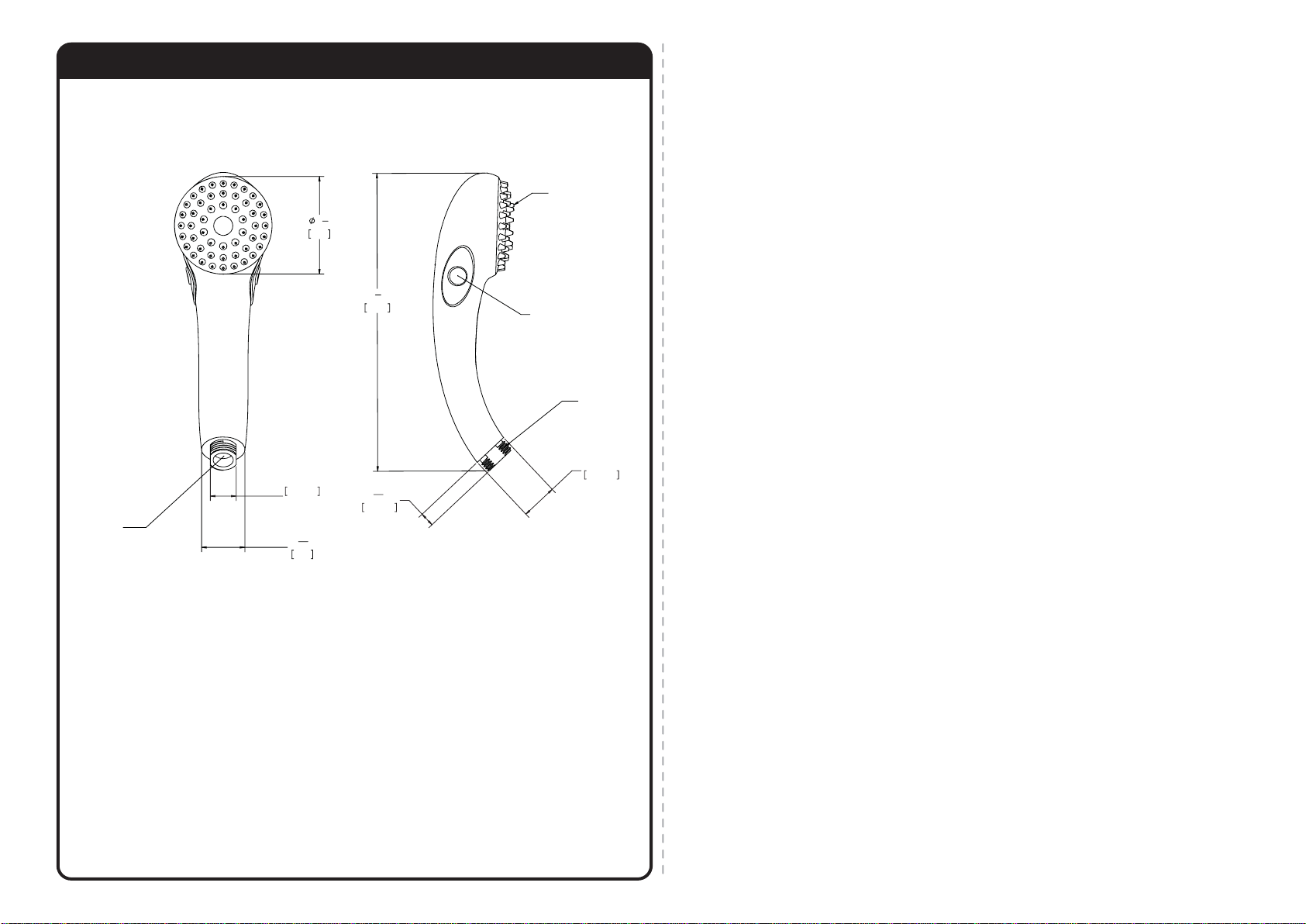
ROUGH IN DIMENSIONS
VS-100-PC-E175
Max. Flow Rate: 1.75 gpm (6.6 L/min)
Min. Flow Rate: 1.3 gpm (4.9 L/min) @ 45psi
FOR USE WITH AUTOMATIC COMPENSATING VALVES
RATED AT 5.7 L/MIN (1.5 GPM) OR LESS.
VS-100-PC-E2
Max. Flow Rate: 2.0 gpm (7.6 L/min)
Min. Flow Rate: 1.5 gpm (5.7 L/min) @ 45psi
FOR USE WITH AUTOMATIC COMPENSATING VALVES
RATED AT 6.6 L/MIN (1.75 GPM) OR LESS.
VS-100-PC
Max. Flow Rate: 2.5 gpm (9.5L/min)
Min. Flow Rate: 2.0 gpm (7.6 L/min) @ 45psi
FOR USE WITH AUTOMATIC COMPENSATING VALVES
RATED AT 7.6 L/MIN (2.0 GPM) OR LESS.
13
32
"
10.16mm
8
1
2
"
215.90
1"
25.40mm
1/2-14 NPSM
MALE THREADED
INLET
50 RUBBER
TIPPED SPRAYS
PAUSE
BUTTON
.714in
18.14mm
ACROSS
FLATS
3
1
8
"
79.38
1
3
16
"
30.18
FLOW CONTROL
INSERTED INTO
HANDLE
Page 11
INSTRUCTIONS FOR MODELS
92-VS-153-ADA-02
For additional assistance or service please contact:
SPEAKMAN
®
Company
400 Anchor Mill Road
New Castle, DE 19720
800-537-2107
www.speakman.com
VS-153-ADA -30 -36
VS-153-30-RT
HELPFUL TOOLS & SUPPLIES:
TOOLS AND SUPPLIES
Level
Measuring
Tape
Phillips
Screwdriver
Pencil
Drill
Drill Bit
No.10/5.5mm
Tile Drill Bit
x/xx”
Mounting Hardware
(included)
Additional warranty information can be found at:
www.speakman.com
WARRANTY
MAINTENANCE
• Cover your drain to prevent loss of parts. Be sure
to follow all tool manufacturers safety guidelines.
• Use caution when drilling into walls to avoid
electrical and plumbing lines hidden within
the wall.
SAFETY TIPS
IMPORTANT
• Meets the ANSI standard 250 lbs. pull-test for
grab bars and ADA lever handle for adjusting
slide bar.
• The VS-153-ADA Slide Bar meets ADA pull force
requirements only. It is not intended to replace an
ADA Grab Bar.
• Do not over-tighten any connections or damage
may occur.
• Be sure to read instructions thoroughly before
beginning installation.
Your new Speakman Product is designed for years of
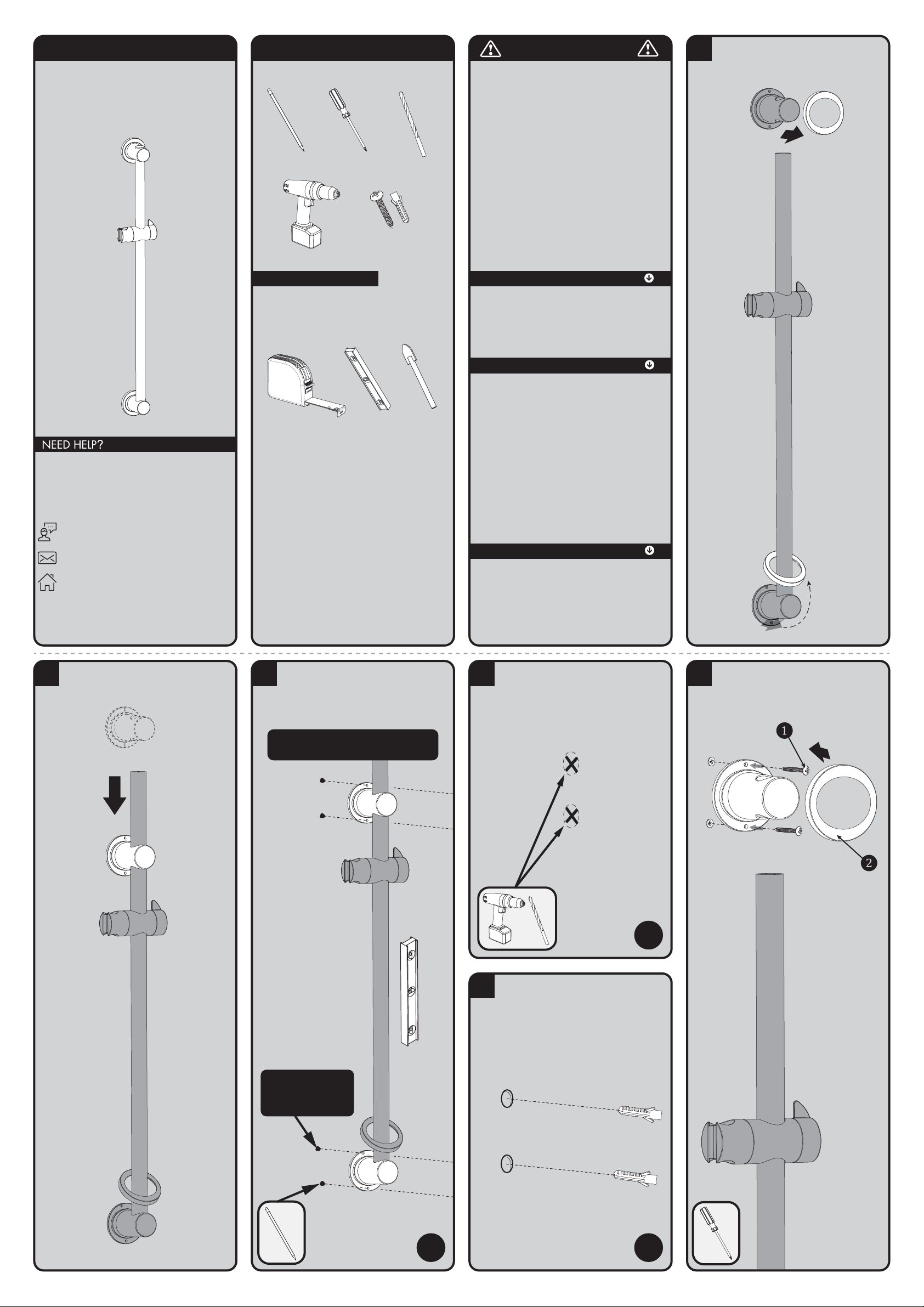
1
Remove Decorative Cover Plate from Upper
Mounting Bracket. Slide Lower Decorative Cover
Plate up and over Lower Mounting Bracket as
shown below.
2
Position the Upper Mounting Bracket over the
Slide Bar. Ensure the mounting location is within
the usable range of the hand shower hose.
3
Hold the Slide Bar against the wall in the chosen
location. Adjust the Upper Mounting Bracket
height location. Using a pencil, mark the Drill
Hole positions (x4) for the Upper and Lower
Mounting Brackets. Ensure the Slide Bar is level
vertically.
NOTE: If using as a Grab Bar, be sure to fasten
securely to proper bracing within the wall.
NOTE: Upper mounting
hole is intentionally off
center to allow for easier
installation.
X4
4
If mounting directly to wood stud or
a wood stud behind drywall, proceed
to Step 6. If mounting to tile or masonry wall,
Drill holes (x4) in the marked locations using a
No. 10 (0.1935 inches/5.5 mm) masonry drill
bit to make a hole approximately 1 3/8 inches
(35 mm) deep.
Ø No.10/5.5mm
X4
5
Push the Plastic Anchors (x4) into the drilled
holes. Ensure the plastic anchors are flush with
the wall. (Note: Plastic Anchors provided may
not be suitable for all types of wall construction,
seek professional help if in doubt).
X4
6
Remove Upper Mounting Bracket from Slide Bar.
Secure Upper Mounting Bracket in place using
the Mounting Screws provided (1) with a Phillips
Screwdriver. Reinstall the Decorative Cover Plate
(2) to the Upper Mounting Bracket.
trouble-free performance. Keep it looking new by
cleaning it periodically with a soft cloth. The use of harsh
chemicals and abrasives on any of the Speakman custom
finish products may damage the finish and void the
product warranty. Please be sure to only use approved
cleaners. Please contact Speakman for any clarification
of acceptable cleaners.
Page 12
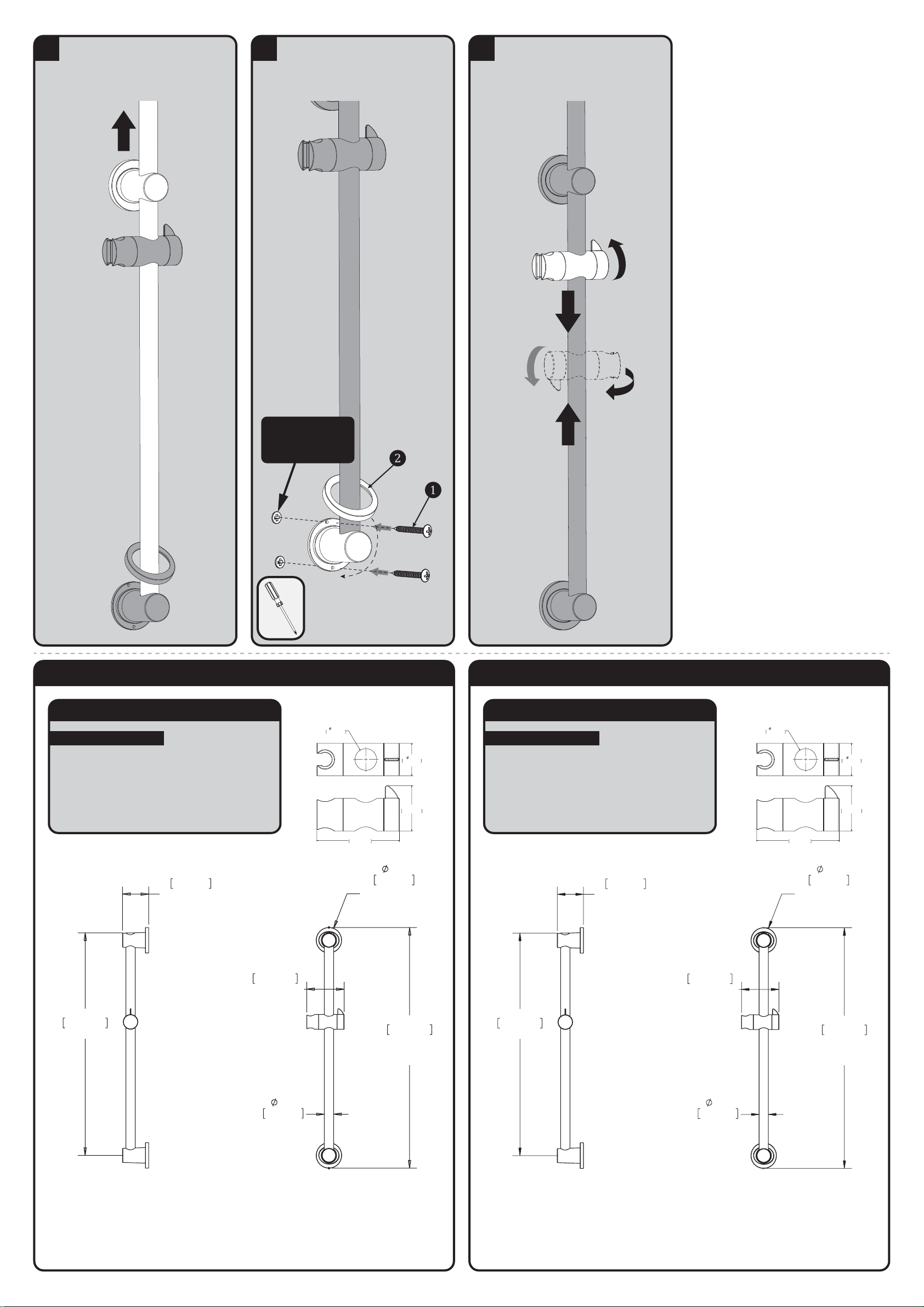
7
Position the Slide Bar flush against the mounting
surface and push the Slide Bar through the hole
in the Upper Mounting Bracket.
8
Secure the Lower Mounting Bracket (1) in place
to the wall using the Mounting Screws provided
with a Phillips Screwdriver. Reinstall the Lower
Decorative Cover Plate (2) to the Lower
Mounting Bracket.
NOTE: Upper mounting
hole is intentionally off
center to allow for easier
installation.
9
Orient the Hand Held Shower Bracket to your
desired position. Adjustments are made by
rotating the Locking Handle 1/4 turn
counter-clockwise to release the position, and
1/4 turn clockwise to lock into the desired
position.
LOCK
UNLOCK
VS-153-ADA ROUGH-IN DIAGRAM
SPEAKMAN
®
DIMENSIONS SUBJECT TO CHANGE WITHOUT NOTICE.
NOTES:
COMPLIANCE:
ADA COMPLIANT
• Meets the ANSI standard 250 lbs. pull-test for
grab bars and ADA lever handle for adjusting
slide bar.
• The VS-153-ADA Slide Bar meets ADA pull force
requirements only. It is not intended to replace an
ADA Grab Bar.
1.3in
31.75mm
REF
5.1in
128.80mm
REF
HOLDER ARM
LENGTH
3.5in
87.63mm
REF
MOUNT COVER
TYP
32.5in
825.82mm
MAX
OVERALL
HEIGHT
24.1in
611.19mm
LENGTH OF BAR
3.5in
89.66mm
REF
MOUNT HEIGHT
TYP
2.78in
70.73mm
5in
128.80mm
1.34in
33.91mm
2in
50.80mm
TYP.
VS-153-ADA-30 / VS-153-30-RT ROUGH-IN DIAGRAM
SPEAKMAN
®
DIMENSIONS SUBJECT TO CHANGE WITHOUT NOTICE.
NOTES:
COMPLIANCE:
ADA COMPLIANT
• Meets the ANSI standard 250 lbs. pull-test for
grab bars and ADA lever handle for adjusting
slide bar.
• The VS-153-ADA Slide Bar meets ADA pull force
requirements only. It is not intended to replace an
ADA Grab Bar.
1.3in
31.75mm
REF
5.1in
128.80mm
REF
HOLDER ARM
LENGTH
3.5in
87.63mm
REF
MOUNT COVER
TYP
32.5in
825.82mm
MAX
OVERALL
HEIGHT
30in
763.59mm
LENGTH OF BAR
3.5in
89.66mm
REF
MOUNT HEIGHT
TYP
2.78in
70.73mm
5in
128.80mm
1.34in
33.91mm
2in
50.80mm
TYP.
Page 13
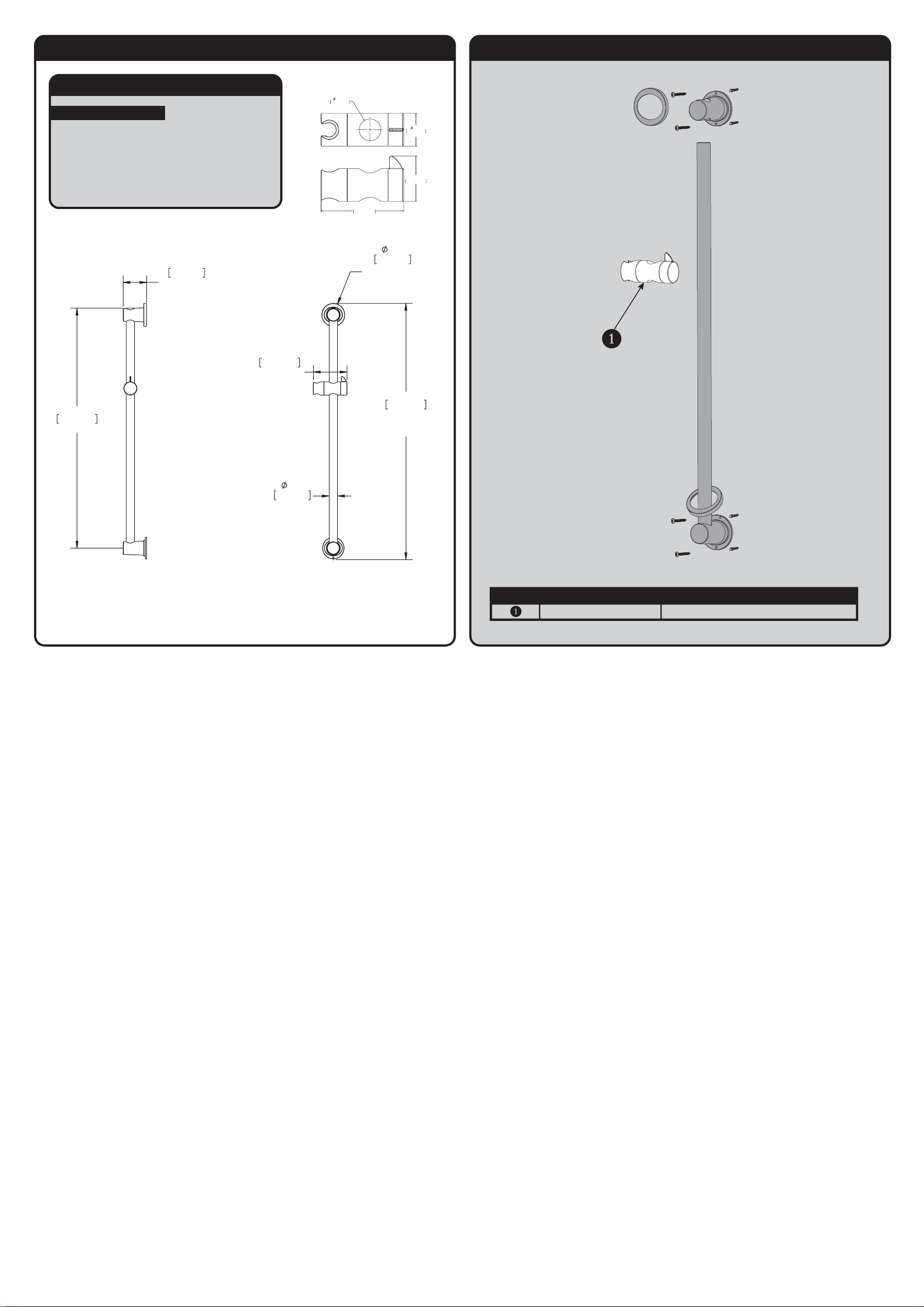
VS-153-ADA REPAIR PARTS
SPEAKMAN
®
RPG56-0038-XX *XX = FINISH VS-153-ADA HOLDER REPAIR PART GROUP
ITEM NO. PART NO. DESCRIPTION
VS-153-ADA-36 ROUGH-IN DIAGRAM
SPEAKMAN
®
DIMENSIONS SUBJECT TO CHANGE WITHOUT NOTICE.
NOTES:
COMPLIANCE:
ADA COMPLIANT
• Meets the ANSI standard 250 lbs. pull-test for
grab bars and ADA lever handle for adjusting
slide bar.
• The VS-153-ADA Slide Bar meets ADA pull force
requirements only. It is not intended to replace an
ADA Grab Bar.
5.1in
128.80mm
REF
HOLDER ARM
LENGTH
1.3in
31.75mm
REF
3.5in
87.63mm
REF
MOUNT COVER
TYP
38.5in
976.63mm
MAX
OVERALL
HEIGHT
3.5in
89.66mm
REF
MOUNT HEIGHT
TYP
36.0in
914.40mm
LENGTH OF BAR
2.78in
70.73mm
5in
128.80mm
1.34in
33.91mm
2in
50.80mm
TYP.
 Loading...