

Page 1
INSTRUCTIONS FOR MODELS
92-CPT-1001-01
For additional assistance or service please contact:
SPEAKMAN
®
800-537-2107
www.speakman.com
CPT-1001
TOOLS AND SUPPLIES
Phillips
Screwdriver
Measuring
Tape
Warranty information can be found at:
www.speakman.com
WARRANTY
MAINTENANCE
Cover your drain to prevent loss of parts.
SAFETY TIPS
IMPORTANT
• Be sure to read instructions thoroughly before
beginning installation.
• Do not over-tighten any connections or damage
may occur.
• Be sure to have properly adjusted the Temperature
Limiting Stop (TLS) as per the Valve Installation
Instructions before installing Valve Trim.
Your new Speakman Product is designed for years of
trouble-free performance. Keep it looking new by
cleaning it periodically with a soft cloth. The use of harsh
chemicals and abrasives on any of the Speakman custom
finish products may damage the finish and void the
product warranty. Please be sure to only use approved
cleaners. Please contact Speakman for any clarification
of acceptable cleaners.
1
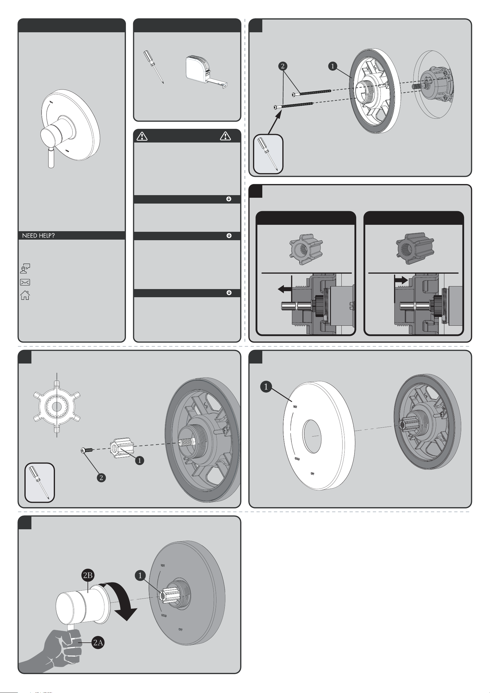
Clean wall surface. Place Mounting Base (1) onto the valve, align mounting holes, and secure with
supplied screws (2).
2
Verify the position of the Spindle within the Mounting Plate, as shown below. If the end of the
Spindle extends beyond the Mounting Plate, then use the Shallow Mount Adapter. If the end of the
Spindle is flush to, or is within the Mounting Plate, then use the Deep Mount Adapter.
FOR SHALLOW MOUNT APPLICATION
FOR DEEP MOUNT APPLICATION
3
Confirm that Valve is in the “Off” position. Place appropriate Connector (1) on to the Spindle of the
Valve, making sure to orient the Connector so that one set of Splines are in a perfectly vertical
position. Secure Connector with 8-32 screw provided (2).
Splines in Vertical Position
4
Place Escutcheon (1) on Mounting Base. Take care to orient the Escutcheon as shown below.
5
Align Handle Assembly with Connector (1) and Escutcheon as shown below. Keep Handle (2A) in a
stationary vertical position and place over Connector (1) and engage the Splines of the Connector
with the Handle Assembly. Keep Handle in the vertical position as you thread Handle Hub (2B) on
to Mounting Base. Tighten until snug.
Page 2
CPT-1001 REPAIR PARTS
SPEAKMAN
®
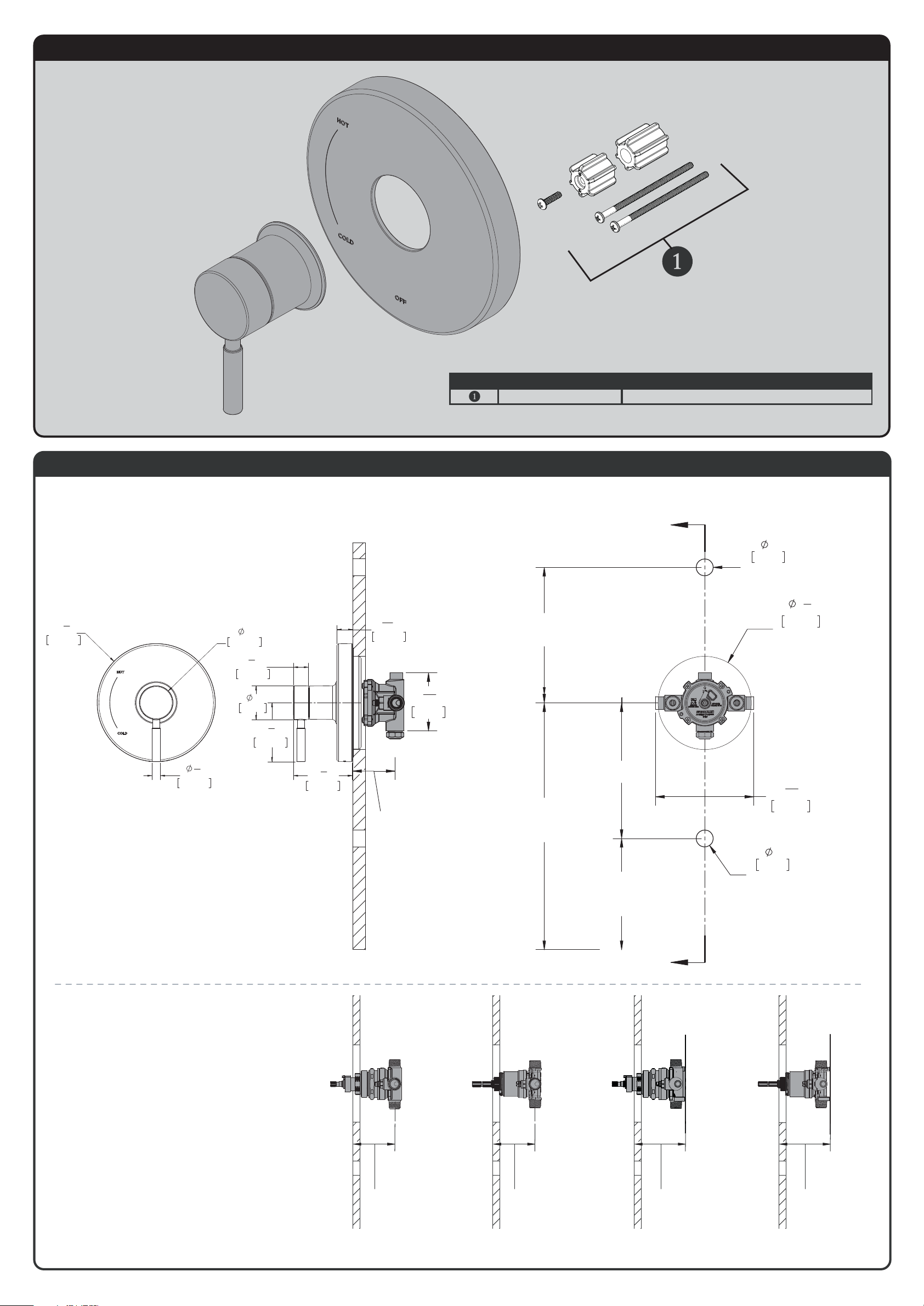
RPG05-0874 SCREWS AND SPLINE ADAPTERS
ITEM NO. PART NO. DESCRIPTION
CPT-1001 ROUGH-IN DIAGRAM
SPEAKMAN
®
DIMENSIONS SUBJECT TO CHANGE WITHOUT NOTICE.
VALVE MOUNTING IS SHOWN FOR REFERENCE ONLY.
VALVE IS NOT INCLUDED WITH CPT-1001.
1"
25mm
HOLE FOR
SHOWER ARM
5
1
2
"
140mm
HOLE FOR
VAVLE ACCESS
5
13
16
"
147mm
1'-9"
[533mm]
4"
[102mm]
TO TOP OF
TUB LEDGE
4'-6"
[1.4 METERS]
TO FLOOR
(SHOWER INSTALL ONLY)
6'-6"
[2 METERS]
TO FLOOR
1"
25mm
HOLE FOR
TUB SPOUT
A
A
2-1/2" [64mm] MINIMUM
3-1/2" [89mm] MAXIMUM
ROUGH IN DEPTH
3
7
16
"
87mm
SECTION A-A
R3
1
2
"
88.9mm
2"
50.4mm
1
2
"
12.7mm
3
1
2
"
88.4mm
15
16
"
23.6mm
7
8
"
22.6mm
2"
51mm
3
1
2
"
88.8mm
NOTE: TRIM FITS DIFFERENT VALVES. ROUGH-IN
DIMENSIONS PROVIDED FOR REFERENCE ONLY.
2-1/2" MIN
CPV-T CPV-PB CPV-T-PXC
CPV-T-PXE
CPV-PB-PXC
CPV-PB-PXE
[64mm]
3-1/2" MAX
[89mm]
(ADJUSTMENT)
2-1/2" MIN
[64mm]
3-1/2" MAX
[89mm]
(ADJUSTMENT)
3-3/16" MIN
[81mm]
4-3/16" MAX
[106mm]
(ADJUSTMENT)
3-1/8" MIN
[80mm]
4-1/8" MAX
[105mm]
(ADJUSTMENT)
 Loading...