

Page 1

OWNER’S MANUAL
ERS-1.0 Web Server
Ethernet/RS232 Adapter
Revision 1
Page 2

KIT INCLUDES:
• (1) RSA-1.0
• (1) ERS-1.0
• (1) 6 ft. DB9F to DB9F Null Modem Cable
• (1) ERS-1.0 Quick Start Guide
EQUIPMENT NEEDED:
• (2) 6 ft. Network Patch Cord (Straight Through)
• (1) Fully Functional MZC System programmed with MODE keypads using the latest Firmware
• (1) Wireless Router
• (1) ERS-1.0 Web Server Kit
SYSTEM OVERVIEW
The ERS creates an web interface on a wireless home network to allow control of a MZC via computer (running a supported
internet browser) and/or an iPhone
tion of the ERS-1.0's GUI.
®
/iPod Touch®. This manual will give you step by step instructions on the set-up and opera-
TABLE OF CONTENTS
WIRELESS NETWORKING 101............................. 2
SYSTEM SETUP...................................................... 4
HOOK UP DIAGRAM.......................................... 5
WEB BROWSERS.................................................. 8
GUI INTERFACE.................................................... 9
MODE 3.1 BUTTON NUMBERING LAYOUT......... 10
1
Page 3

WIRELESS NETWORKING 101
OVERVIEW:
This section is to provide you with the basic knowledge on how networks are set up and operate.
Step 1 - CHOOSE YOUR WIRELESS EQUIPMENT
The rst step is to make sure that you have the equipment you need. As you’re looking for products in stores or on the Internet,
you might notice that you can choose equipment that supports three different wireless networking technologies: 802.11a,
802.11b, 802.11n, and 802.11g. We recommend 802.11g, because it offers excellent performance and is compatible with
almost everything.
Shopping list
• Internet (not required for ERS1.0 interface to work)
• Wireless Router
• A Computer with built-in Wireless Networking Support, Wireless Network Adapter, iPhone
Understanding Networks
Networks are fairly simple to understand if you think of them as a neighborhood. Imagine each house has a mailbox with a
number and each street has a name and each neighborhood is identied, as is each city, state and country. An IP address is
simply a way of providing an individual address to each network “node” or component. These unique addresses are used to
search and communicate for other network nodes. If two locations have the same address, you can imagine the trouble the
mail carrier might have delivering the mail to the right house.
In a typical conguration, a local network uses one of the designated “private” IP address subnets and a router on that
network has a private address (such as 192.168.1.1) in that address space. The router is also connected to the Internet with
a single “public” address (known as “overloaded” NAT) or multiple “public” addresses assigned by an ISP. As trafc passes
from the local network to the Internet, the source address in each packet is translated on the y from the private addresses
to the public address(es). The router tracks basic data about each active connection (particularly the destination address
and port). When a reply returns to the router, it uses the connection tracking data it stored during the outbound phase to
determine where on the internal network to forward the reply; the TCP or UDP client port numbers are used to de-multiplex
the packets in the case of overloaded NAT, or IP address and port number when multiple public addresses are available, on
packet return. To a system on the Internet, the router itself appears to be the source/destination for this trafc.
®
or iPod Touch
®
A Wireless Router
The router converts the signals coming across your Internet connection into a wireless broadcast, sort of like a cordless phone
base station. Be sure to get a wireless router, and not a wireless access point.
A Wireless Network Adapter
Network adapters wirelessly connect your computer then to your wireless router. If you have a newer computer you may
already have wireless capabilities built in. If this is the case, then you will not need a wireless network adapter. If you need to
purchase an adapter for a desktop computer, buy a USB wireless network adapter. If you have a laptop, buy a PC card-based
network adapter. Make sure that you have one adapter for every computer on your network.
Note: To make setup easy, choose a network adapter made by the same vendor that made your wireless router. For example,
if you nd a good price on a Linksys router, choose a Linksys network adapter to go with it. To make shopping even easier, buy
a bundle, such as those available from D-Link, Netgear, Linksys, Microsoft, and Buffalo. If you have a desktop computer, make
sure that you have an available USB port to plug the wireless network adapter into. If you don’t have any open USB ports, buy
a hub to add additional ports.
Step 2 - CONNECT YOUR WIRELESS ROUTER
Since you’ll be temporarily disconnected from the Internet, print these instructions or copy and paste them to a word doc or
clipboard to allow access once the internet connection is down. Do this before you go any further. First, locate your cable
modem or DSL modem and unplug it to turn it off. Next, connect your wireless router to your modem. Your modem should stay
connected directly to the Internet. Later, after you’ve hooked everything up, your computer will wirelessly connect to your
router, and the router will send communications through your modem to the Internet.
Note: The instructions below apply to a Linksys wireless router. The ports on your router may be labeled differently, and the images may look different on your router. Check the documentation that came with your equipment for additional assistance.
• If you currently have your computer connected directly to your modem: Unplug the network cable from the back of your
computer, and plug it into the port labeled Internet, WAN, or WLAN on the back of your router.
•If you do not currently have a computer connected to the Internet: Plug one end of a network cable (usually included with
your router) into your modem, and plug the other end of the network cable into the Internet, WAN, or WLAN port on your
wireless router.
2
Page 4

• If you currently have your computer connected to a router: Unplug the network cable connected to the Internet, WAN, or
WLAN port from your current router, and plug this end of the cable into the Internet, WAN, or WLAN port on your wireless
router. Then, unplug any other network cables, and plug them into the available ports on your wireless router. You no longer
need your original router, because your new wireless router replaces it.
Next, plug in and turn on your cable or DSL modem. Wait a few minutes to give it time to connect to the Internet, and then plug in
and turn on your wireless router. After a minute, the Internet, WAN, or WLAN light on your wireless router should light up, indicating
that it has successfully connected to your modem.
Step 3 - CONFIGURE YOUR WIRELESS ROUTER
Using a standard network patch cord, you should temporarily connect your computer to one of the open network ports on
your wireless router (any port that isn’t labeled Internet, WAN, or WLAN). If you need to, turn your computer on. It should automatically connect to your router.
Next, open Internet Explorer (PC users) and type in the address to congure your router. You might be prompted for a password. The address and password you use will vary depending on what type of router you have, so refer to the instructions
included with your router.
As a quick reference, this table shows the default addresses, usernames, and passwords for some common router manufacturers.
ROUTER ADDRESS USERNAME PASSWORD
3Com http://192.168.1.1 admin admin
D-Link http://192.168.0.1 admin
Linksys http://192.168.1.1 admin admin
Microsoft Broadband http://192.168.2.1 admin admin
Netgear http://192.168.0.1 admin password
Internet Explorer will show your router’s conguration page. Most of the default settings should be ne, but you should congure three things:
1. Your wireless network name, known as the SSID. This name identies your network. You should choose something unique
that none of your neighbors will be using.
2. Wireless encryption (WEP) or Wi-Fi Protected Access (WPA), which help protect your wireless network. For most routers, you
will provide a passphrase that your router uses to generate several keys. Make sure your passphrase is unique and long
(you don’t need to memorize it).
3. Your administrative password, which controls your wireless network. Just like any other password, it should not be a word
that you can nd in the dictionary, and it should be a combination of letters, numbers, and symbols. Be sure you can remember this password, because you’ll need it if you ever have to change your router’s settings.
The exact steps you follow to congure these settings will vary depending on the type of router you have. After each conguration setting, be sure to click Save Settings, Apply, or OK to save your changes.
Now, you should disconnect the network cable from your computer.
Step 4 - CONNECT YOUR COMPUTERS
If your computer does not have wireless network support built in, plug your network adapter into your USB port, and place the
antenna on top of your computer (in the case of a desktop computer), or insert the network adapter into an empty PC card
slot (in the case of a laptop). Windows XP will automatically detect the new adapter, and may prompt you to insert the CD
that came with your adapter. The on-screen instructions will guide you through the conguration process.
Note: The steps below only apply if you’re using Windows XP Service Pack 2. If you’re running Windows XP and you don’t have
Service Pack 2 yet, plug your computer into your wireless router and download and install Windows XP Service Pack 2
Windows XP should show an icon with a notication that says it has found a wireless network.
Follow these steps to connect your computer to your wireless network:
1. Right-click the wireless network icon in the lower-right corner of your screen, and then click View Available Wireless Networks. If you run into any problems, consult the documentation that came with your network adapter. Don’t be afraid to
call their tech support.
3
Page 5

2. The Wireless Network Connection window should appear and you should see your wireless network listed with the network
name you chose. If you don’t see your network, click Refresh network list in the upper-left corner. Click your network, and
then click Connect in the lower-right corner.
3. Windows XP prompts you to enter a key. Type the encryption key that you wrote down earlier in both the Network key and
Conrm network key boxes, and then click Connect.
4. Windows XP will show its progress as it connects to your network. After you’re connected, you can now close the Wireless
Network Connection window. You’re done.
Note: If the Wireless Network Connection window continues to show Acquiring Network Address, you may have mistyped the
encryption key.
SYSTEM SETUP
Step 1 - ROUTER SETUP
In this scenario, we will use a Linksys wireless router. Default setting for a Linksys Router is 192.168.1.1. With a computer connected to the wireless router and all related equipment powered up, open up the internet browser on your computer and
type in 192.168.1.1 and press ENTER. Log in window will appear. Enter the default user name and password for the Linksys router
(default is admin/admin). See Figure 1. Default static IP setting for the ERS-1.0 is xxx.xxx.x.254. The default setting on the Linksys
router does not need to be changed to accommodate the ERS-1.0’s IP address. Save settings and power down the router.
Other manufacturers might need to have their settings adjusted to be sure there are no IP address conicts on the network.
Congurations will vary for this set up, please make sure to read the router’s owner’s manual for details.
NOTE: The DHCP address range for the router must not include xxx.xxx.x.254 or there could be potential IP conicts on the
system with dynamic devices.
Figure 1
Step 2 - MZC SETUP
Download your project and the latest rmware to the MZC. For information on creating an EZ Tools project and downloading
rmware, please refer to the EZ Tools Programming Guide.
There is no special setup in the EZ Tools software for the ERS interface, however, there are buttons on the GUI interface that do
relate to the project (keep this in mind when programming). See Page 7 for call outs on GUI buttons.
Step 3 - RSA SETUP
Download the "MZC Control Firmware" into the RSA please refer to the EZ Tools Programming guide for details.
4
Page 6
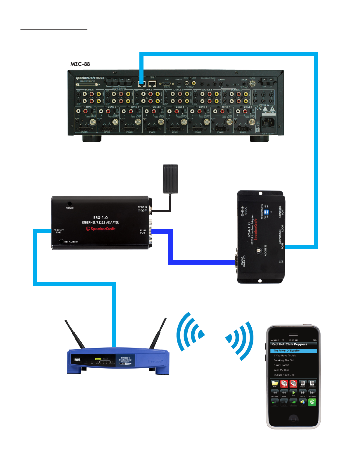
HOOK UP DIAGRAM
MZC-88
ERS-1.0 Web Server (Included)
CAT 5 Patch Cord - 50 FT. Max
5V
Power
Supply
(Included)
RSA-1.0 (Included)
CAT 5 Patch Cord
Wireless Router
6ft DB9F to DB9F
Null Mode Cable
(Included)
WiFi
(Required to download MZC
Control Firmware)
®
iPhone
5
Page 7

SYSTEM SETUP (continued)
With all related devices connected, apply power to the wireless router; once the router has fully booted up, then apply power
to the MZC, then the ERS-1.0. Boot up time may vary depending on how many zones are congured on the system.
Step 4 - iPhone® SETUP
Accessing the ERS
To access the ERS-1.0 web browser, select the Safari browser on your iPhone
ERS-1.0 (192.168.254). The ERS-1.0's GUI will pop up (See Fig-
ure 2).
®
and type in the static IP address for the
Figure 2
Save a Quick Reference Icon
To save A Quick Reference icon on the iPhone
®
main
source page, press the "+" sign at the bottom of the web
page as shown in Figure 3.
Then select "Add to HOME Screen". See Figure 4.
Figure 3
6
Figure 4
Page 8

SYSTEM SETUP (continued)
Notice the SpeakerCraft icon shows up. You can call the
link whatever you like, in this case SpeakerCraft, then press
ADD. See Figure 5.
Figure 5
Notice that the icon is now on the main page. To access
the MZC system, press the icon. See Figure 6.
Figure 6
7
Page 9
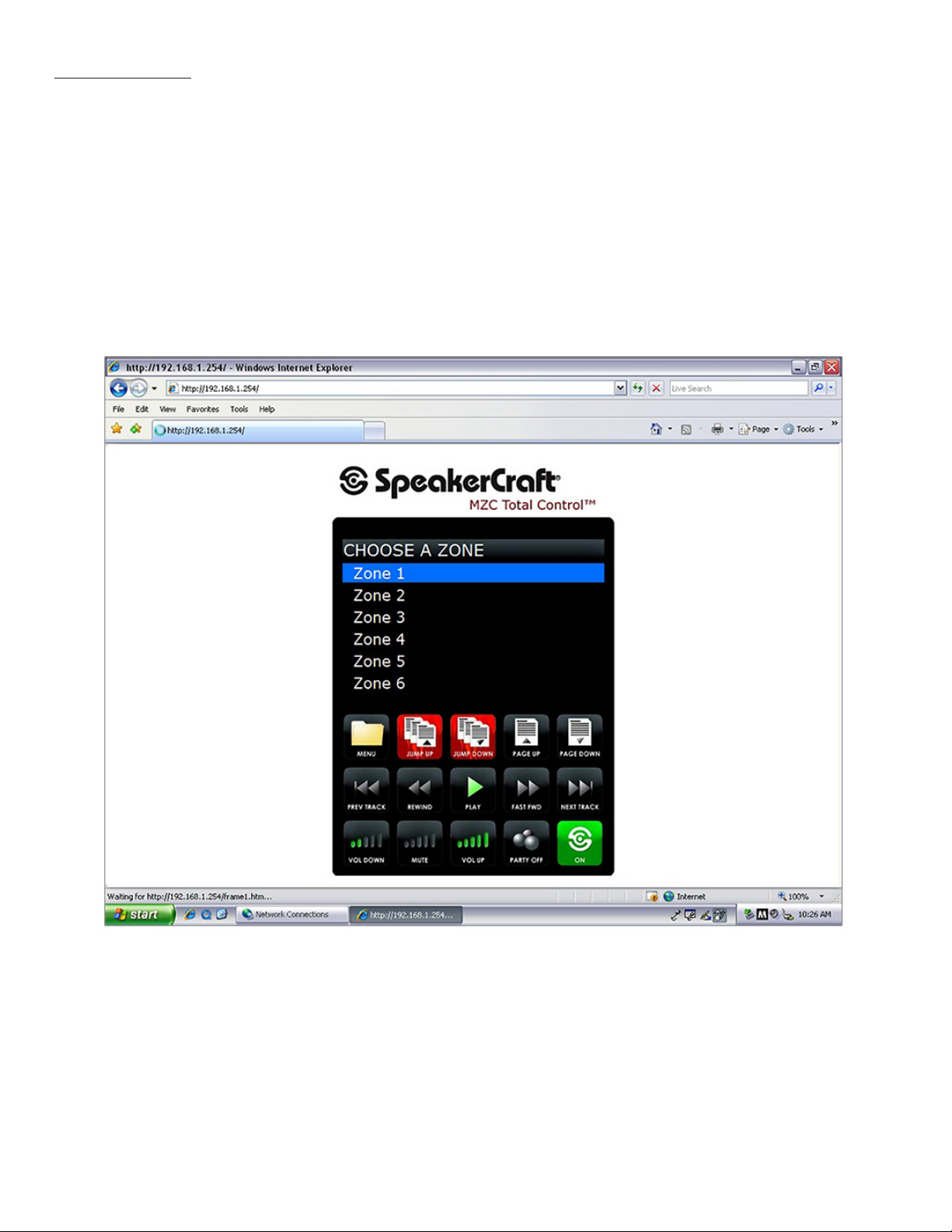
WEB BROWSERS
The ERS can be accessed through a web browser on a PC or MAC. Simply type in the IP address for the ERS into the browser
(192.168.1.254) as shown below. See Figure 7.
Supported Internet browsers:
•Internet Explorer on PC
•Safari on PC
•Safari on MAC
•Safari on iPod Touch
•Safari on iPhone
Figure 7
®
®
8
Page 10

GUI INTERFACE
Here is a layout of the main page and the button relation to the MZC project.
Predened buttons:
Predened buttons are buttons that cannot be programmed in any way.
Programmable Buttons:
Any button that has a number reference to it can have command placed under it. Button numbers relate only to the MODE
keypad. You do not need to have a mode keypad in the system for this functionality to work but you do need to have a MODE
keypad programmed in the EZTools project. Please see Figure 8 for the MODE keypad button number layout.
Once a zone is selected,
the GUI will show all
sources programmed in
that zone.
Pre-dened as “Menu
Back”
Related to button No.79 in
EZTool Project.
Related to button No.78 in
EZTool Project.
Related to button No.82 in
EZTool Project. Shows next
state.
Related to button No.74 in
EZTool Project. Shows feedback of which state it is in.
Pre-dened Menu Up/
Down 5%.
Pre-dened as Page Up/
Page Down
(Next/Previous 5 in a List).
Relates to Button No.81 in
EZTool Project.
Relates to Button No.77 in
EZTools Project.
Pre-dened 3-step Volume
Up or Down.
Pre-dened as Party Mode
On/Off. Shows feedback
of which state it is in.
9
Power Off only relates to
Project Button No.76
Page 11

MODE 3.1 BUTTON NUMBERING LAYOUT
74
76
73
Figure 8
75
77
78
81
79
80
82
LIMITED 2-YEAR WARRANTY
Defective products must be shipped, together with proof of purchase, prepa id insured to the SpeakerCraft Authorized Dealer from whom they were
purchased, or to the SpeakerCraft factory at the address li sted on this installation instruction manual. F reight collect shi pments will be refused. It is
preferable to shi p thi s product i n the original shi pping container to lessen the chance of transit damage. In any case, the risk or loss or damage in
transit is to be borne by the purchaser. If upon examination at the Factory or SpeakerCraft Authorized Dealer it is determ ined that the unit was defective in materials or workmanship at any time duri ng this warranty period, SpeakerCraft or the SpeakerCraft Authorized Dealer wi ll, at its option, repair
or replace this product at no additional charge, except as set forth below. If this model is no long er availabl e and can not be repaired effectively,
Speake rCraft, at its sole option may replace the unit with a current model of equal or g reater value. In some cases where a new model is subs tituted,
a modification to the mounting su rface may be required. If mounting surface modification is required, SpeakerCraft assumes no responsi bility or
liab ilit y for such modification. All replaced parts and product become the property of SpeakerCraft Inc. Products replaced or repaired under this
warranty will be returned to the original reta il purchaser, w ithin a reasonable time, freight prepaid.
This warranty does not include service o r parts to repair damage caused by accident, disaster, misuse, abuse, neglig ence, i nadequate packing or
shipping procedures, commercial use, voltage inputs in exces s of the rated ma ximum of the unit, or ser vice, repair or modification of the product
which has not been authorized or approved by SpeakerCraft. This warranty al so excludes norma l cosmetic deterioration caused by envi ronmental
conditions. This warrant y will be voi d if the Serial number on the prod uct has been rem oved, tampered with or defaced.
This warranty is in lieu of all other exp ressed warranties. If th e product is defective in material s or workmanship as wa rranted above, the purchaser's
sole remedy shall be repair or repl acement as provided above. In no event w ill SpeakerCraft be liable for any i ncidental or consequential damages
ari sing out of the use or inability to use the product, even if SpeakerCraft Inc. or a Spea kerCraft Inc. Author ized D ealer has been advi sed of the possibi lity of such damag es, or for any claim by any other pa rty. Some states do not allow the exclusi on or limitation of consequential damages, so the
above limitation and exclusion may not appl y.
All implied warranties on the p roduct are limited to the duration of this expressed wa rrant y. Som e states do not all ow limitation on the length of an
implied War ranty. I f the original retail purchaser resides in such a state, this lim itation does not apply.
If you have any questions regarding this or any other SpeakerCraft product, please contact your local Authorized SpeakerCraft dealer, or you may
contact SpeakerCraft toll-f ree at 1- 800-4 48-0976 for immediate custo mer as sistan ce. We are availab le to assist you every weekday, except holidays,
between the hours of 7:00 a.m. and 5:00 p.m.
940 Columbia Ave., Riverside CA 92507 | USA (800) 448 0976 Fax (951) 787 8747 International +1 951 787 0543 | www.
speakercraft.com
LIT97605(rev4)
LIT07110A
 Loading...