

Page 1
W
hile vacuum-tube-based HF
power amplifiers still dominate
the amateur radio market, we
are starting to see more and more new
solid-state HF amplifiers becoming
available. This is due to lower prices for
high-power FETs (field-effect transistors), higher costs for high-voltage
power-supply components and tubes,
and the convenience of no-tune operation. A new solid-state amplifier introduced at Dayton this year is the Expert
1K-FA amplifier from SPE in Rome, Italy.
Array Solutions (www.arraysolutions.
com) is the exclusive U.S. distributor of
this amplifier.
The Expert 1K-FA amplifier provides
1000 watts PEP/900 watts CW on 160–
10 meters, and 700 watts PEP/CW on 6
meters. The amplifier is quite compact
at just 11 inches wide, 6 inches high, and
13.5 inches deep and weighs about 45
pounds. Included within this amplifier
package is a 120/240-VAC linear power
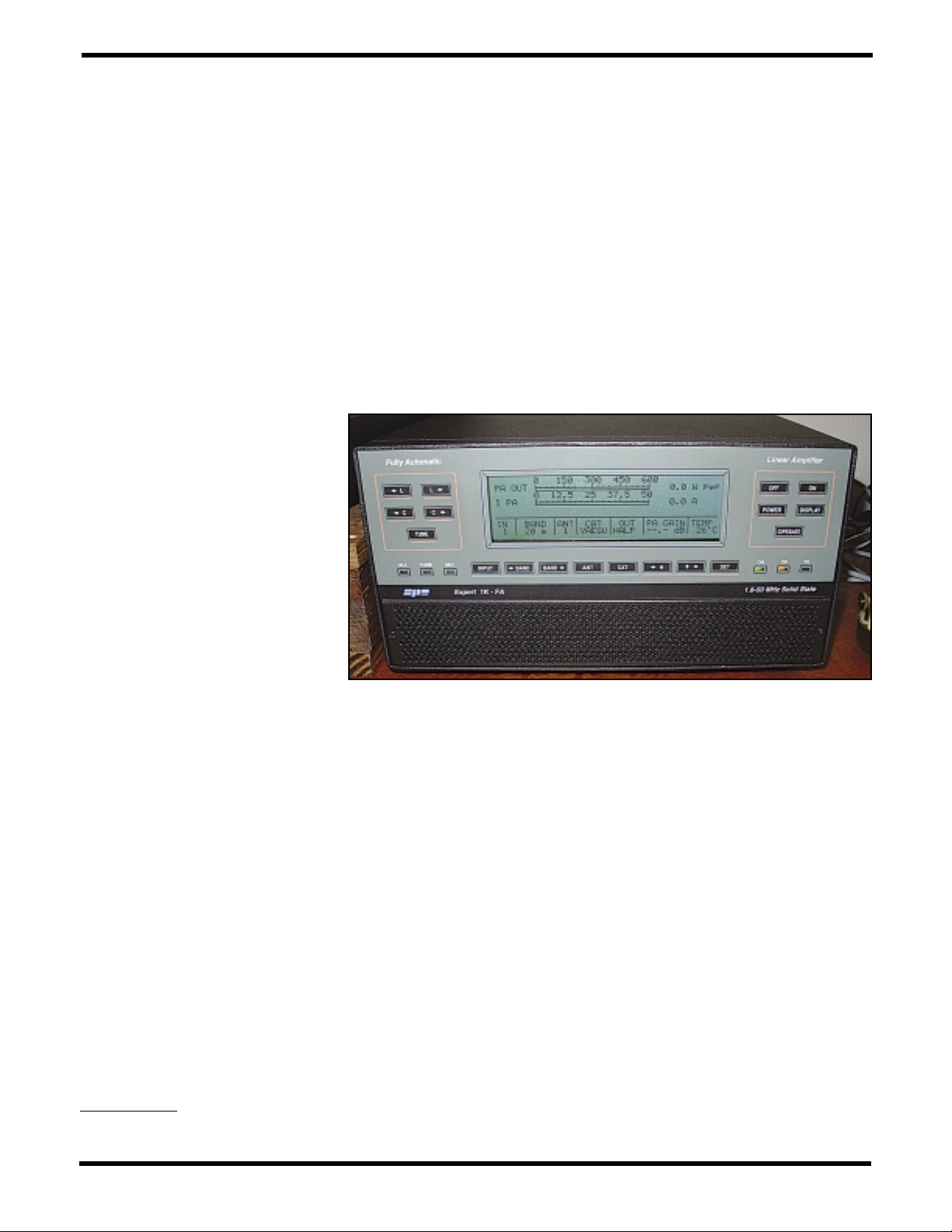
supply. SPE chose a linear power supply with a highly efficient toroidal hypersil transformer to eliminate the possibility of switching tones. Photo A shows the
attractive front panel with LCD screen,
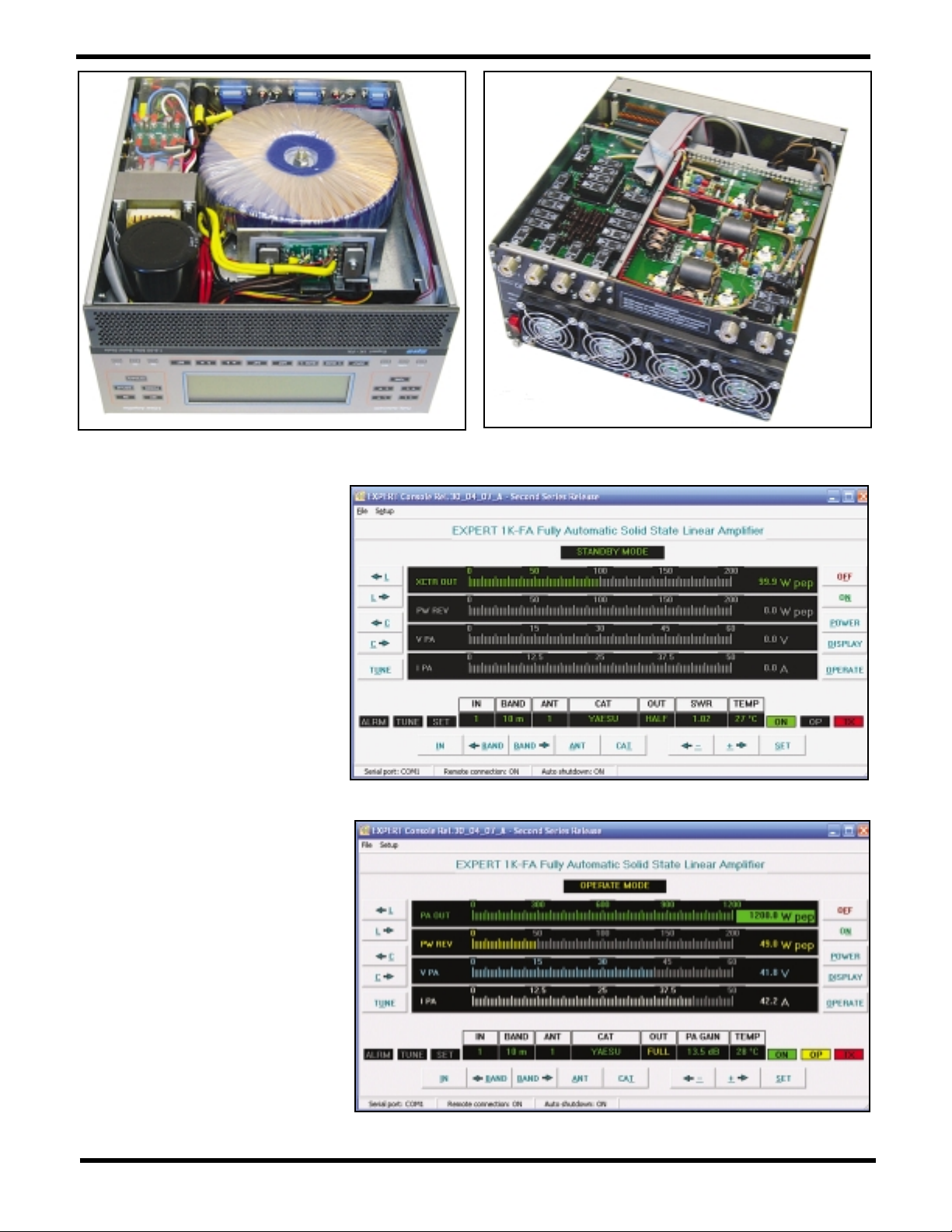
photo B is an inside view of the power
supply (bottom) portion of the amplifier,
and photo C shows the RF compartment
with the internal RF shields removed.
The Expert 1K-FA can serve as the
center of a fully coordinated contest station, as it includes a two-transceiver
input control interface, a four-port
antenna switch, and a high-power automatic antenna tuner that can separately manage antennas on each of the four
antenna ports. Thus, any two transceivers can be connected to any one of
four antennas. When the amplifier is off,
transceiver 1 is connected to antenna
1, while antenna ports 2, 3, and 4 are
grounded. The two transceiver control
interfaces are 15-pin D-connectors that
provide band-data interfaces to most
transceivers. Even if your transceiver
has no band-data output, the Expert 1KFA senses the keyed transceiver’s frequency and automatically selects that
transceiver and the correct antenna.
There are also two separate ALC
(automatic level control) and amplifier
keying interfaces for the two transceiver inputs. The ALC interfaces are very
well thought out. When you connect the
ALC cables between the 1K-FA and
your transceivers, the amplifier automatically controls the drive power from
the selected radio necessary to give you
the full amplifier output. Therefore, you
can leave your transceivers set for maximum power all the time, and the 1K-FA
will control the transceiver power levels
from band to band with no operator
adjustments necessary. Also, when the
amplifier is placed in “Standby,” you
have full transceiver power available.
However, what if you don’t need the full
1-KW power? The 1K-FA has a “Power”
switch on the front panel that lets you
select between half power (approximately 500 watts) and full power. Again,
the amplifier controls the ALC line as
necessary to control the drive so there
is nothing for you to do other than punch
the “Power” button. Five-hundred watts
is 7 dB more power (over an S-unit) than
the typical 100-watt transceiver, which
often is all it takes to make the difference in snagging that DX contact.
The 1K-FA also has a rear SO2R
(Single-Operator 2-Radio
1
) connector
for contesters. This is a receive-only
port that permits you to listen on one
transceiver while you are operating
your main transceiver. If you hear a station you want to work on the secondary
transceiver, you just start transmitting
with this transceiver and the amplifier
Compact and (relatively) lightweight, the SPE Expert 1K-FA amplifier is a
no-tune, solid-state, legal-limit “smart” power amplifier designed with the
contester in mind. AD5X puts it through its paces…
CQ Reviews:
SPE Expert 1K-FA Solid-State
HF/50-MHz 1-KW Power Amplifier
BY PHIL SALAS,* AD5X
*1517 Creekside Drive, Richardson, TX 75081
e-mail: <[email protected]>
Photo A– The SPE 1K-FA solid-state amplifier puts out 1000 watts on 160–10
meters and 700 watts on 6 meters.
Page 2
automatically switches to this transceiver and the correct antenna. I’ve
found this convenient even outside of
contests for monitoring 6 meters with
my ICOM IC-706MkIIG with a 6-meter
loop on the SO2R connector, while
operating HF with my Yaesu FT-1000
MkV. When something pops up on the
6-meter calling frequency, I just hit the
PTT button on my 706 and the amplifier automatically selects that radio and
my 6-meter beam. Pretty neat!
Full monitoring of the Expert 1K-FA is
provided by the amplifier’s LCD screen.
From this screen you can accurately
monitor amplifier FET drain voltage and
current, exciter and amplifier output
power and reflected power (with simultaneous bar-graph and digital readings),
the selected transceiver and antenna,
and an alarm log. The LCD screen provides menus for programming the amplifier for radio-specific interfaces and
antenna selections as well. You can also
interconnect the amplifier to a PC with a
supplied RS-232 cable and display (in
color) all amplifier parameters and control the 1K-FA from your computer. If
your desktop computer does not have an
RS-232 port, I found that a cheapie USBto-serial converter works just fine.
Photos D and E show the display indicating exciter power when the amplifier
is in standby, and full amplifier output
power, respectively.
Amplifier Protection
The Expert 1K-FA has a very extensive
protection system. The parameters
monitored and acted on by the amplifier are heatsink temperature, FET drain
Photo D– Computer screen display when the amplifier is in standby.
Photo E– Computer screen display when the amplifier is operating at full
power output.
Photo B– The bottom (power supply) portion of the
amplifier. Look at that power transformer!
Photo C– RF section of the amplifier with the internal shields
removed.
Page 3
voltage, PA current, SWR, reflected
power (which includes reflected harmonic power), input overdrive, and
power combiner balance. Any fault condition provides an audible and visual
alarm and puts the amplifier into the
standby/bypassed condition. All alarms
are also stored in an “Alarm History”
buffer which can be called up on the
amplifier’s LCD display.
Connecting the Amplifier
The 1K-FA comes strapped for 240
VAC, so you first need to decide on
whether or not to change this to 120
VAC. The amplifier will easily operate
from 120 VAC in the half-power mode.
I measured the 120-VAC AC current at
10.5 amps when operating at halfpower. I also found that I could operate
the amplifier at full power on 120 VAC,
but I did have it connected to an AC
branch that is separate from the AC circuit from which my two transceivers are
powered. I measured the full-power
120-VAC current at 19 amps, so you
really should run the amplifier from 240
VAC unless you have a separate 120VAC 20-amp circuit available.
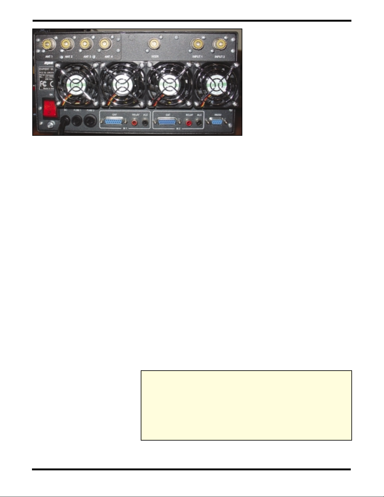
As discussed earlier, all the connectors for automatic interfacing with up to
two transceivers and four antennas are
provided on the rear of the amplifier, as
can be seen in photo F. SPE provides
two sets of RCA-type cables for ALC
and amplifier keying, and two 15-pin Dconnectors for making up transceiver
interface cables. In my case I wanted to
connect both my Yaesu MkV and my IC706 transceivers to the amplifier. I purchased a 9-pin female D-connector
from RadioShack for the Yaesu CAT
end of the cable, and used one of the
SPE-supplied 15-pin D-connectors for
the amplifier side of the interface cable.
For the IC-706MKIIG, I used an Ameri-
tron ARB-704 transceiver/amplifier buffer which provides ALC and amplifier
keying outputs from the transceiver’s
accessory socket. For the IC-706MkIIG
band-data information, I made a CI-V
cable using a 3.5-mm mono plug for the
ICOM end, and the second SPE-supplied 15-pin D-connector for the amplifier end. Detailed instructions in the
amplifier manual show how to make
cables for virtually any transceiver.
Next I went into the 1K-FA setup
menu and set the interfaces for the
Yaesu and ICOM radios. I also set the
default selected antennas for each
radio and trained the internal auto-tuner
for each antenna on the different bands.
Performance
My amplifier testing included measuring the amplifier power output into a
legal-limit dummy load and checking
the amplifier’s internal power metering
against an external Array Solutions
PowerMaster digital wattmeter. I measured key-down, string of “dits,” and
PEP SSB power on both the 1K-FA
internal power meter and the external
PowerMaster. As you can see in Table
I, the 1K-FA does a good job of meeting its typical power-output specifica-
tions. It is interesting to note that the
PowerMaster typically reads 0.5–1 dB
more power than the amplifier metering.
The amplifier measures power at the
input to the internal auto-tuner, and the
PowerMaster measures power at the
output of the auto-tuner. The internal
auto-tuner is always in-line and cannot
be bypassed. Therefore, these measurements seem to indicate the intrinsic loss of the auto-tuner.
On the Air
Most of my operating during the evaluation period was on 160, 80, 40, and 20
meters using my Yaesu MkV, and on 6
meters using the IC-706MkIIG. Operation is truly easy in that the amplifier
automatically selects the keyed radio
and the primary antenna previously
chosen for that radio and band. You literally don’t need to worry about which
microphone or key you start using, or
which antenna needs to be connected.
Your pre-programmed radio-vs.-antenna is taken care of for you by the amplifier. Of course, you can manually
change these combinations at any time.
Finally, as a CW operator I really appreciated the smooth QSK (break-in keying) operation of the amplifier.
Conclusion
The SPE 1K-FA is definitely an amplifier to consider. With its multi-radio, multiantenna, SO2R, and auto-tuner features, this amplifier is very easy to use—
from normal rag-chewing to contesting
and DXing. Introductory price is $3,975.
For more information, including a downloadable user’s manual, check the
Array Solutions website at <http://
www.arraysolutions.com>.
Note
1. Single-Operator 2-Radio (SO2R) is a popular entry category in some contests. It permits
a single contester to operate on one band while
monitoring for new score multipliers on another band on a second radio, and then to briefly
switch to that second radio to make the contact
for a new multiplier.
Photo F– Interfaces for transceivers and antennas are well-marked and self-
explanatory. Note the SO2R connector.
Amp PM Amp PM Amp PM
Band Key-Down Key-Down “Dits” “Dits” PEP PEP
160m 1178 932 1118 970 975 1200
80m 1115 946 1033 980 1161 1044
40m 938 915 1018 930 1004 937
20m 850 740 950 810 1070 957
17m 1011 870 1100 1007 1200 1100
15m 1100 1025 1075 1000 1200 1062
12m 1031 936 950 950 1143 953
10m 1200 1025 1200 1115 1200 1100
6m 765 616 810 760 818 745
Table I– Amplifier power-output measurements, where Amp = internal amplifier
meter reading; PM = external PowerMaster meter reading. See text for discussion
of differences in readings, all of which are in watts.
Reprinted with permission from CQ Magazine, October 2007
 Loading...