

Page 1
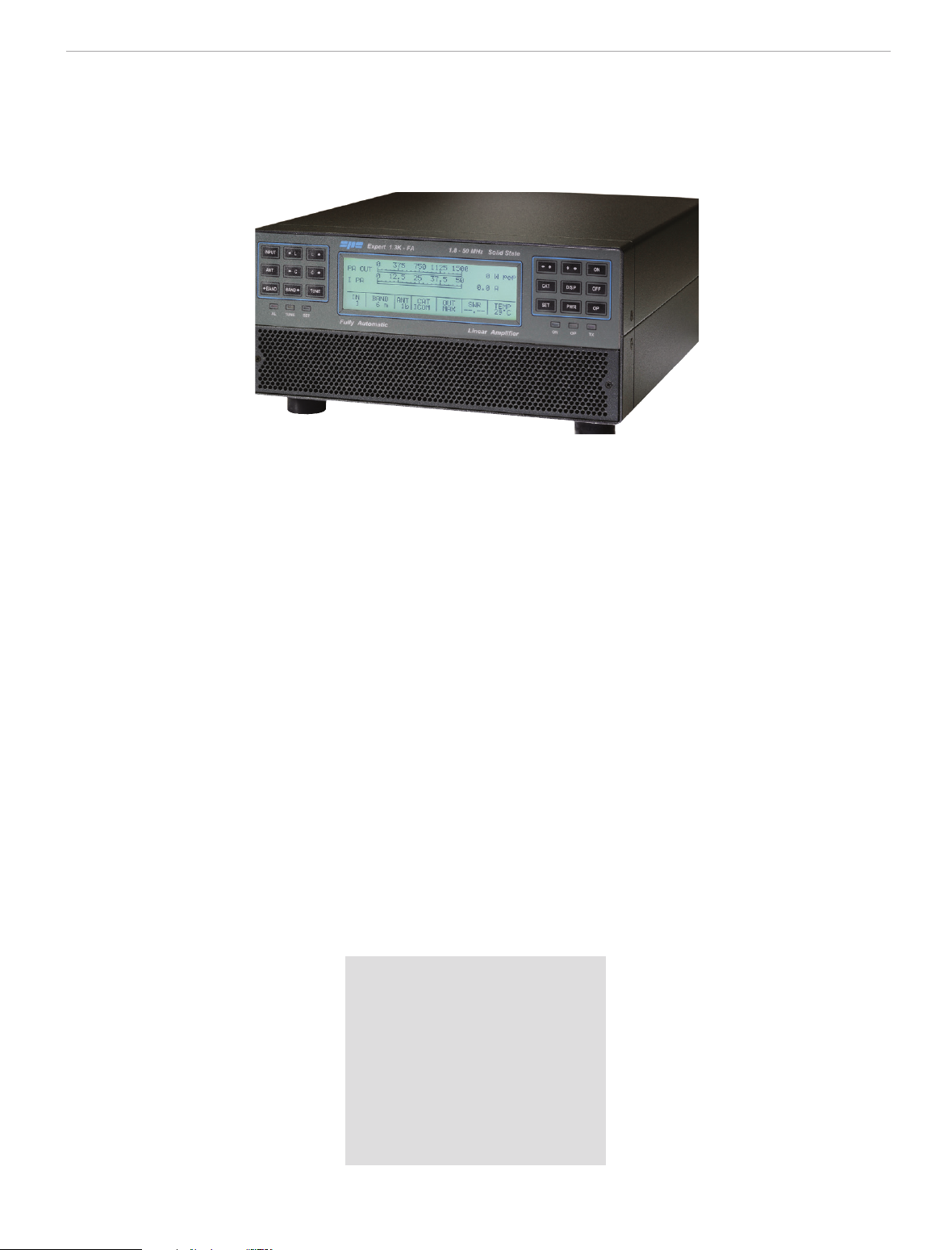
SPE Expert 1.3K-FA Solid
State Linear Amplifier
Reviewed by Mark Wilson, K1RO
QST Contributing Editor
In 2009 we reviewed a new
solid-state power amplifier
from Italy, the SPE 1K-FA.1
That amplifier covered 160
through 6 meters with output power typically 1 kW
PEP for SSB and 900 W
for CW on the HF bands,
700 W at 6 meters, and 500
HALF POWER
W (
tended operation using digital or other high
duty cycle modes. That compact amplifier
weighs 44 pounds. In 2013, we reviewed
the SPE 2K-FA. That amplifier had no
problem delivering legal-limit output from
160 through 6 meters, and it dropped back
to the
MID
W output during extended digital operation. It is larger than the 1K-FA but still
smaller than typical legal-limit tube-type
amplifiers and weighs 55 pounds. Both of
these amplifiers are still available.
The subject of this review, SPE’s 1.3KFA, fits between the two older models in
power output and price but brings some
new technology to the table. The 1.3K-FA
covers 160 through 6 meters and operates at reduced power on the 4 meter (70
MHz) band available in other parts of
the world. In the
review unit delivers 1300 to 1500 W on
all bands except 6 meters, where output
is 1100 W. With the
1000 – 1100 W, and 500 – 600 W in
The amplifier automatically switches to a
lower power during extended high duty
cycle operation (RTTY, for example) or for
amplifier protection (high antenna SWR,
for example).
The 1.3K-FA uses just one LDMOSFET
power transistor rather than the six earlier
generation MOSFETs used in the other
models. The LDMOSFET offers quite a
bit of gain, so amplifiers for the US market
include attenuation at the input to comply
with the 15 dB gain maximum required
by FCC regulations. The review unit typically requires 30 – 35 W for full output and
setting) for ex-
power setting for 1000 – 1100
MAX
power setting, the
MID
setting it delivers
LOW
exhibits higher gain at lower drive levels.
Our amplifier includes a built-in automatic
antenna tuner (ATU) that will match SWR
of up to 3:1 on HF and 2.5:1 on 6 meters.
The 1.3K-FA is also available without
the antenna tuner. The amplifier has four
antenna connectors, as well as RF input,
ALC, transmit-receive relay, and band data
connections for two transceivers. A builtin switchmode power supply supplies 50
V for the LDMOSFET. That’s reduced to
about 40 V for the
about 33 V for
from 100 to 255 V ac, but operation from a
standard 15 or 20 A household 120 V line
will likely result in reduced output.
The front panel LCD is 5 × 1.5 inches and
displays the amplifier’s settings, operating
conditions, and menus. Backlight brightness and contrast are adjustable. Indicators
along the bottom show radio, band and
.
antenna selected, CAT (transceiver interface) setting, output level (
MID
power setting and
LOW
. The supply works
MAX, MID, LOW
Bottom Line
The SPE Expert 1.3K-FA supplies near legal limit power from
160 through 6 meters and includes
sophisticated transceiver interfaces
and antenna switching. The built-in
antenna tuner makes it tolerant of
less-than-perfect antennas. For those
with well matched antenna systems,
the amplifier is available without the
tuner at significant cost savings.
SWR on the amplifier side
of the ATU, and temperature. The upper portion of
the display shows RF output
(both bar graph and numerical display) and PA current
when the amplifier is ready
to operate. A front panel
switch changes the upper
display to PA voltage, indi-
cators showing that the fans are
running, and SWR on the antenna
side of the tuner. In standby the LCD
shows exciter power (up to 200 W) and
SWR on the antenna side of the ATU.
The entire package is compact and weighs
just 21 pounds (16.5 pounds without the
automatic antenna tuner) — less than half
the weight of the 1K-FA and roughly the
same size. All that power from such a tiny
box is amazing to someone who grew up in
the days of tube-type amplifiers that were
hard to move around the shack.
Setup
The first step after unpacking the amplifier is reading through the manual, which
is supplied in PDF format on a CD-ROM
or downloadable from the Expert Linears
website. While you could likely get the amplifier set up and running for basic operation without reading the manual, there are
quite a few features to learn about.
As with most power amplifiers, the user
supplies and installs the ac line plug. In my
case I needed a 240 V, 20 A connector to
match the outlet in my station. The power
supply senses the input voltage automati-
),
cally, so there are no jumpers or menu settings involved.
Figure 9 shows the (many) rear panel connections. There are separate sets of RF
input (SO-239), TR relay (phono), ALC
(phono), and transceiver interface/band
data (DB-15) connectors for two radios.
The 1.3K-FA is capable of interfacing with
transceivers from all major brands, including Elecraft, FlexRadio, Icom, Kenwood,
TEN-TEC, and Yaesu. Only the RF input
and TR relay connections are absolutely
required because the amplifier uses a
8 July 2016 ARRL, the national association for Amateur Radio
®
www.arrl.org
Page 2
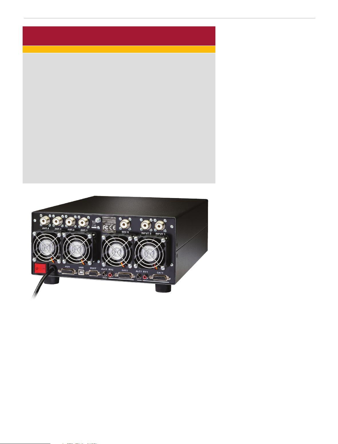
Table 2
SPE Expert 1.3K-FA, serial number 153700175
FCC ID number 2ADK5GC324809
Manufacturer’s Specifications Measured in ARRL Lab
Frequency range: All amateur frequencies in 160, 80, 60, 40, 30, 20, 17, 15,
the range of 1.8 to 29.7 MHz, 50 to 54 MHz 12, 10, 6 meters.*
and 70 to 70.5 MHz.
Power output: Up to 1500 W, 1300 W typical As specified, except 1100 W
(Max); 800 W (Mid); 450 W (Low); 600 W on 6 meters.*
(typical) at 70 MHz.
Driving power required: Not specified. 25 – 35 W typical for 1300 – 1500 W
PEP output (1100 W at 6 meters).
Spurious and harmonic suppression: HF: 57 dB (typical), 49 dB worst case
HF, >60 dB; 6 meters, 65 dB. (40 meters); 6 meters, 64 dB. Meets
FCC requirements.
Third order intermodulation distortion (IMD): 3rd/5th/7th/9th (14 MHz, 1300 W PEP):
30 to 35 dB below PEP typical. –31/–39/–57/–55 dB.
TR relay switching time: Not specified. Unkey to key, 13 ms; key to unkey, 5 ms.
Primary power requirements: 100 – 255 V ac, Tested at 240 V ac. Operation from 120 V
47 – 63 Hz. may result in reduced output power.
Size (height, width, depth): 4.7 × 11 × 15 inches; weight, 21 lbs.
Price: $4995 with automatic antenna tuner; $3795 without automatic antenna tuner.
*In the US, the legal power limit on 30 meters is 200 W PEP output and on 60 meters it is
an ERP of 100 W PEP relative to a half-wave dipole. A 4 meter exciter was not available
at the time of testing.
and the radio was talking to the amplifier.
The instruction manual provides quite a
bit of information and helpful diagrams
for those who want to make their own
cables.
Next I used the menu to set up the amplifier for my antennas. There are four antenna connectors on the rear panel. The
ANTENNA
menu lists all bands from 160
through 4 meters. You select the proper
antenna connector (1 – 4) for each band,
or NO if you don’t have an antenna for that
band. You can set two antennas for each
band and select between them with the
front panel
ANT
switch. When assigning
antenna connectors by band, you can also
chose whether or not to use the automatic
antenna tuner for that band. Note that you
can set up two “banks” of antenna settings — A and B — which would come in
handy if you use the amplifier in multiple
locations.
Antenna Tuner
The internal automatic antenna tuner
(ATU) is specified to match loads with an
SWR of up to 3:1 (2.5:1 on 6 meters). The
manual warns to use antennas having SWR
less than 1.5:1 without the ATU. When
SWR exceeds 1.7:1, the amplifier protection circuitry gives a
and drops the power back to
HIGH SWR
MID
warning
. Above
2:1 the amplifier switches to standby.
Figure 9 — Rear-panel view of the SPE Expert 1.3K-FA amplifier. The four antenna connectors are
at the upper left, while the RF input for two radios and the SO2R connector are at the upper right.
Along the bottom are connectors for interfacing two transceivers and USB and serial ports for com
puter connectivity/remote control.
frequency counter that can sense the RF
input when you transmit and adjust accordingly. You can change bands by speaking a
syllable or two, or sending a dit or two on
CW. Use of the band data cable is “highly
recommended,” however, so that the amplifier follows transceiver frequency changes
without transmitting.
When we ordered the amplifier, we also
ordered transceiver interface cables from
Dan Tassel, KC5PCB, who is associated
with the US distributor. One set was for an
Icom IC-7100 in the Lab and the other for
a Kenwood TS-590S in my station. In my
case, one end connected to the
CAT1
jack
on the back of the amplifier and the other
end had connectors for the
and
REMOTE
jacks on my transceiver. No
COM
(RS-232)
other cables were required because TR
relay and ALC connections are also available on the amplifier’s
To complete this step, I next went to
CAT
connectors.
CAT
menu, selected Kenwood and 9600 baud,
My antenna system is pretty well matched,
but I did need to use the tuner on 160, 40,
and 17 meters. Setup is easy. Each band
is divided into segments shown in a chart
in the manual. For example, 160 meters is
divided into 10 kHz segments, 20 meters
uses 50 kHz segments, and 10 meters uses
100 kHz segments. Tune the transceiver
to the center of the first segment. With the
amplifier in standby and the transceiver
-
set to 30 W output or less, press
transmit briefly. The tuner relays click and
typically find a match within a few seconds. Tune to the center of the next segment and repeat the process. Do this for
each band and antenna where the SWR is
higher than 1.5:1. The display shows SWR
on the amplifier and antenna sides of the
tuner simultaneously.
If you’re not happy with the match the
1.3K-FA comes up with, you can adjust
the inductance and capacitance manually
while watching indicators that appear on
the display. I didn’t find that necessary.
TUNE
and
QST® – Devoted entirely to Amateur Radio www.arrl.org July 2016 9
Page 3

The only place I could not find a match
was the very high end of 160 meters,
where my antenna SWR approaches 4:1
and the amplifier flashed a warning that the
SWR was too high. I use 450 Ω balanced
line and an external tuner for my 80 meter
dipole, and in that case turn off the internal tuner. I wasn’t able to try this, but the
manual indicates that the 1.3K-FA can be
connected to the control box of a SteppIR
or Ultrabeam antenna to manage tuning of
those antennas.
It’s a bit tedious, but once the ATU setup is
complete you don’t have to worry about it
again until something changes.
Other Features
Like the other SPE amplifiers, the 1.3KFA uses a microprocessor-based protection
system that monitors heat sink temperature, input power, PA voltage and current,
reflected power and SWR, and RF voltage
on the tuner. Problems are classified as
simple, serious or fatal and the amplifier
handles them in different ways. For simple
problems such as excessive input power,
the amplifier sounds a warning beep and
resets itself. For serious problems, such
as excessive heat sink temperature or high
SWR, the amplifier switches to standby
and an error message with the reason for
the fault flashes on the display and is stored
in memory so that the operator can find
and fix the problem. I tested this protection
a few times by inadvertently transmitting
on the wrong antenna. For a fatal fault such
as a power supply or microprocessor problem, the amplifier power switches off and
might be restarted by cycling the power
switch on the rear panel. The manual recommends contacting the distributor if a
fatal fault occurs.
The 1.3K-FA rear panel has four small fans
that come on when the amplifier is turned
on and run at low speed. Fan speed increases noticeably when you close the TR
switch to transmit and returns to low speed
when you switch back to receive. Fan
speed in receive automatically increases
with heat sink temperature and slows down
as the heat sink temperature drops. Some
people may find the fan noise at higher
speeds bothersome. I wear headphones for
nearly all operation so it wasn’t an issue
for me.
The LCD includes a temperature display
that’s always visible. According to the
manual, if the temperature reaches 75 °C,
the power will drop back to
LOW
until the temperature reaches safe
MID
or even
levels. During routine operation in my
basement location, the temperature tended
to stay between around 40 °C. During
extended CW and RTTY contest operating periods, it would reach the 60 – 65 °C
range. At that point, the fans were running
pretty fast on receive as well as transmit.
Full break-in (QSK) is available for CW
operation. The amplifier uses mechanical
relays, rather than vacuum relays or PIN
diodes, and some operators might find the
clicking bothersome without the use of
headphones.
As with the other models, SPE advertises
the 1.3K-FA as being capable of SO2R
(single operator, two radio) operation. This
technique is used by contest operators to
transmit on one band while listening on
another, and quickly transmitting on the
second band when a needed contact is
found. Normally this is accomplished with
two transceivers, two amplifiers, bandpass
filters, and appropriate switching.
As described previously, the 1.3K-FA has
connections for two radios with independent settings for each. There’s an
SO2R
jack on the back of the amplifier for an
antenna separate from the main antennas,
and this antenna is used only for receiving.
The transceiver connected to the active
input uses the main antennas and antenna
tuner. The other transceiver is connected
to the
SO2R
antenna and can use that antenna for receiving while the active radio
is transmitting. The idea is to use the second transceiver and receive-only antenna
to find a station on another band that you
want to work and then to switch that transceiver to the main transmitting antenna for
that band in order to make the call.
As noted in the 2K-FA review, this capability is somewhat useful but it is not as versatile as how SO2R is typically implemented
with a switching system that allows one
transceiver to use any of the main antennas
not being used by the other. My system is
quite simple and uses an Array Solutions
Six Pak antenna switch (two radios, six
antennas) that is operated manually. The
1.3K-FA manual describes SO2R station
configurations using the amplifier to control an optional SPE SO2R1 switching
unit and BPF1 bandpass filters, but these
units were not available during the review
period.
Note that the manual recommends high
isolation (physical separation) between the
SO2R antenna and main antennas and the
use of bandpass filters for receiver protection. It goes on to say, “In this case, SPE is
not responsible for any damage caused to
equipment.”
The 1.3-FA has USB and RS-232 ports on
the rear panel that can be used to connect
the amplifier to a Windows PC to upgrade
the firmware or for controlling the amplifier. Terminal and control software is
supplied on the CD shipped with the amplifier or available for download from the
SPE website. The remote control software
displays a replica of the amplifier’s front
panel LCD and switches for monitoring
and control.
Final Thoughts
I enjoyed using the SPE Expert 1.3K-FA
at my station for several months, including
extended contest operation in the ARRL
RTTY Roundup and ARRL International
DX Contest. Once I had the amplifier installed and programmed for my station, it
performed flawlessly. There is not much
to say about using it — band changes instantly follow the transceiver, and the amplifier makes power on the selected band.
Temperature stayed within the safe range,
even during extended RTTY contest operation. Its low drive requirement allowed my
transceiver to run cooler.
SPE calls the 1.3K-FA a “1.3 kW solid
state fully automatic amplifier” and it
certainly lives up to that billing. Its light
weight, built-in antenna tuner and widerange power supply make it attractive for
DXpeditions. Those setting up remote stations will want to explore its remote control
and monitoring capabilities.
Manufacturer: SPE (Societa Per
L’Elettronica), Via di Monteverde, 33,
00152 Rome, Italy; www.linear-amplifier.
com. US distributor: Expert Linears Amer-
ica, PO Box 1224, Magnolia, TX 77355; tel
281-259-7877; www.expertlinears.com.
Notes
1
M. Wilson, K1RO, “SPE Expert 1K-FA Linear
Amplifier,” Product Review, QST, Sep 2009,
pp 44 – 47.
2
D. Sumner, K1ZZ, “SPE Expert 2K-FA Solid
State Linear Amplifier,” Product Review, QST,
Nov 2013, pp 54 – 56.
10 July 2016 ARRL, the national association for Amateur Radio
®
www.arrl.org
 Loading...