

Page 1

SmartBox Mounting Page 1 of 5
DOCUMENTATION
Use the provided tempate to determine the location of the mounting bolts. We
have provided mounting bolts for sheetrock (the KAP toggles), wood (the LAG
bolts), and masonry (the expansion bolts).
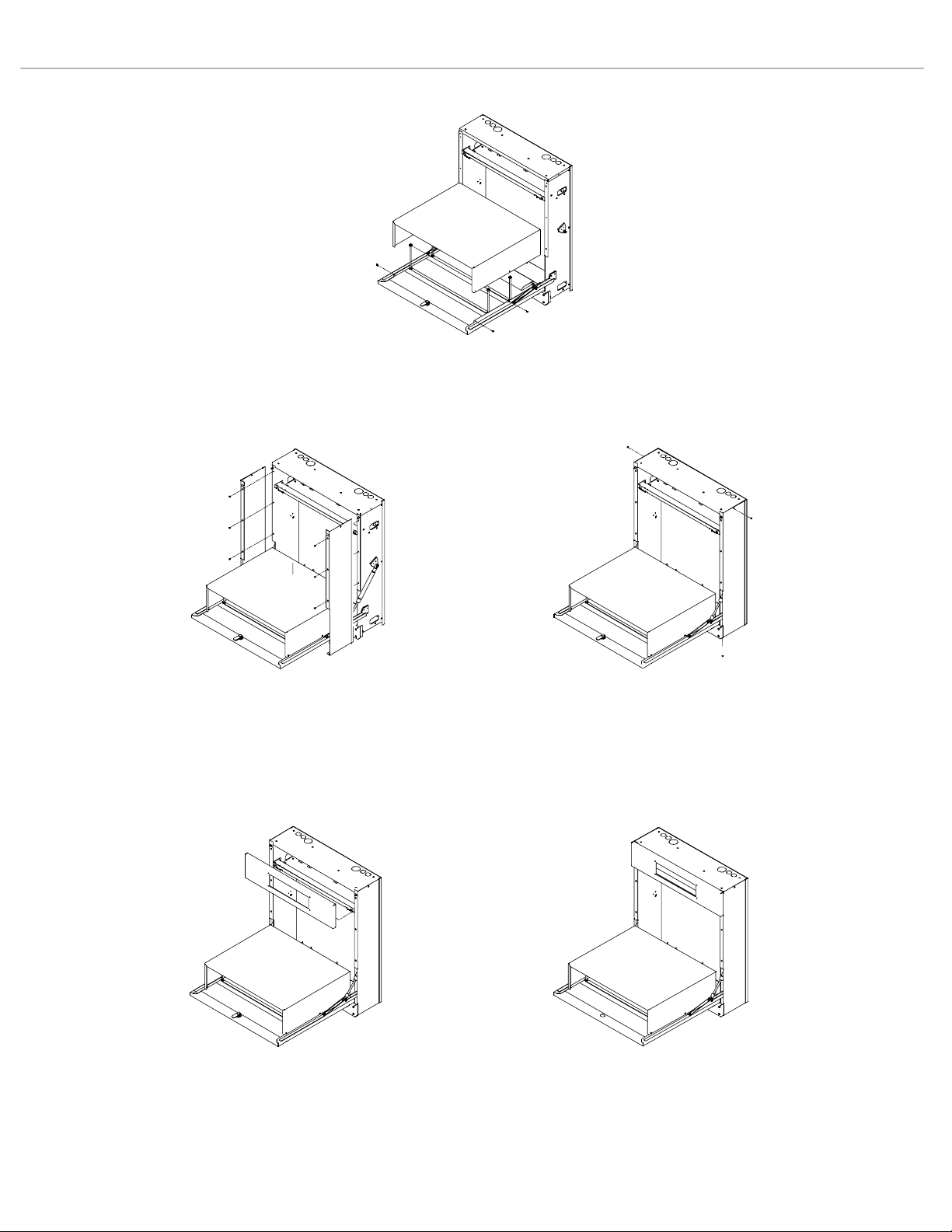
The enclosed Smart Box is fully assembled. Remove the VCR/DVD cover with the
star-point security bit provided. Remove the facia (where the SmartPanel is
installed) by pulling the top towards you. It is held by clips at the top and hinges at
the bottom. Slide the spring hinge pins towards the center. Remove the side
panels by unscrewing the (5) 4-40 screws on each (one is on the bottom of the
unit).
Mount the box to the wall. Install the VCR/DVD player and place the (2) brackets
on the threaded rods. Use the (4) flange nuts provided to tighten the brackets onto
the top of the VCR/DVD.
Route the wires from the VCR/DVD up the sides using the split tubing. Power
should go up one side, video and audio up the other. Use the cable ties and
bases to secure the tubing so that there is a sufficient service loop for the box to
close and open without pinching or straining the cables.
Re-install the VCR/DVD cover, the right and left sides. Re-Install the facia after
you have installed the Smart Panel in it.
If you are using a SP3-AFVP+, it can be mounted to the studs inside the top of the
enclosure with the 4-40 nuts attached to this documentation.
If you have questions, please call us at 877 367 8444 and we would be happy to
walk you through the installation process.
9/13/200 SP Controls, Inc.
(877) 367-8444
S
Page 2
.SmartBox Mounting (PRELIMINARY) Page 2 of 5
Install DVD/VCR
COVER
INSTALL SIDE COVERS
front screws
INSTALL SIDE COVERS
top & bottom screws
INSTALL FACIA ASSEMBLED VIEW
9/13/200 SP Controls, Inc.
(877) 367-8444
Page 3

SmartBox Mounting (PRELIMINARY) Page 3 of 5
Smart Box Wall Preparation
The SmartBox can be mounted to masonry, wood, or sheet rock walls. It will come with mounting screws for each type. It is designed to be
mounted over a finished electrical receptacle box. The back plate of the box has a hole for access to the power receptacles and low voltage
wiring. Under no circumstances is high voltage wiring to be exposed inside the enclosure.
The SmartBox can mount on studs at 16" and 12" centers. The SmartBox can also be mounted to one center stud if no other options are
available. A backing board should be specified in new construction if studs are at 24" centers.
The location of the power receptacle will determine the height of the final box. We recommend that the finished receptacle be mounted at 46"
height. This will achieve the dimensions shown in Figure 2.
4-PLEX for power.
Smart box can be
mounted over finished
outlet with cover plate.
Have electrician place center of
outlet at 46" to achieve proper height
(see following page)
optional backing board
12" centers
16" centers
18"x4.5" clear
hole thru back of
SmartBox to wall
j-box or hole for
low voltage wiring
(size and place
as needed)
smart box back plate
keyhole screw
mounting
locations (10
places)
24.500in.
46in.
20.250in.
24in.
Smart Box wall Infrastructure
Figure 1:
9/13/200 SP Controls, Inc.
(877) 367-8444
Page 4

SmartBox Mounting (PRELIMINARY) Page 4 of 5
ADA Compliance Notes
To the best of our knowledge, we believe that the following mounting arrangement will comply with ADA laws. It your responsibility to verify
that your installation will comply with ALL federal, state, and local laws including ADA requirements.
We have provided the text an diagrams of the applicable ADA rules as a convenience. For more information visit http://www.accessboard.gov/adaag/html/adaag.htm#4.4.
23.8in.
48in.
to top of control
Surface
27in.
24in.
6.1in.
17.7in.
6in.
Figure 2:
Smart Box Mounting Placement
Applicable ADA Regulations
4.4 Protruding Objects.
4.4.1* General. Objects projecting from walls (for example, telephones) with their leading edges between 27 in and 80 in (685 mm and 2030
mm) above the finished floor shall protrude no more than 4 in (100 mm) into walks, halls, corridors, passageways, or aisles (see Fig. 8(a)).
Objects mounted with their leading edges at or below 27 in (685 mm) above the finished floor may protrude any amount (see Fig.
8(a) and (b))
2030 mm) above the ground or finished floor (see Fig. 8(c) and (d)). Protruding objects shall not reduce the clear width of an accessible
route or maneuvering space (see Fig. 8(e)).
4.2 Space Allowance and Reach Ranges.
4.2.5* Forward Reach. If the clear floor space only allows forward approach to an object, the maximum high forward reach allowed shall be
48 in (1220 mm) (see Fig. 5(a)). The minimum low forward reach is 15 in (380 mm). If the high forward reach is over an obstruction, reach
and clearances shall be as shown in Fig. 5(b).
9/13/200 SP Controls, Inc.
. Free-standing objects mounted on posts or pylons may overhang 12 in (305 mm) maximum from 27 in to 80 in (685 mm to
(877) 367-8444
Page 5

SmartBox Mounting (PRELIMINARY) Page 5 of 5
Figure 5b
Maximum Forward Reach over an Obstruction
The maximum level forward reach over an obstruction with knee space below is 25 inches (635 mm).
is less than 20 inches (510 mm) deep, the maximum high forward reach is 48 inches
projects 20 to 25 inches (510 mm to 635 mm), the maximum high forward reach is 44 inches (1120 mm). (4.2.5, 4.25.3)
(1220 mm). When the obstruction
When the obstruction
Figure 8a
Protruding Objects
Walking Parallel to a Wall
9/13/200 SP Controls, Inc.
(877) 367-8444
 Loading...