


PX2-NRC-1142

Contents
Important Safety Instructions ................................................................. i
I. Overview ...................................................................................................1
II. Sample Systems ................................................................................. 2
III. Getting Started ................................................................................... 5
IV. Basic Configuration .......................................................................... 8
V. Advanced Configuration ................................................................... 17
VI. Scheduling Events and Security ..................................................... 27
VII. Email Alerts and Monitoring .......................................................... 29
VIII. Wiring the NRC ............................................................................... 30
IX. Connecting the Devices on the SP Bus .......................................... 31
Troubleshooting .................................................................................... 33
Copyright ......................................................................................... 33
PX2-NRC-1142 User’s Manual November 2009

I. Overview
What is the NRC and what does it do?
The PixiePro
TM
Networked Room Controller
TM
(PX2-NRC-1142) is generally designed to be the central
control device for audiovisual systems. The NRC can be configured, controlled, and monitored via a
friendly Web interface, and controlled from a wall-mounted button panel (sold separately). You can
control virtually any display device, switcher, or peripheral device using the NRC's single RS-232 con-
trol port, one IR control port, and four low-voltage relays. It also has two general purpose input sense
ports that can detect low-voltage relay closure and initiate actions triggered by external events.
How does it control an audiovisual system?
The NRC can function as a stand-alone control device by connecting it to a network and accessing it
with a Web browser on a computer that is connected to the same network. (In fact, using the Web-
based interface is how the NRC must be configured.) Most people will want in-room control in addi-
tion to Web-based control. In those cases, the NRC can be connected to a PixiePro Modular Panel
TM
(PX2-MP-IR) as its front-end "button-pressing" control interface. The NRC will still be the brains in the
installation and will initiate all control actions, while the Modular Panel will simply provide the in-room
button interface.
The NRC is designed to directly control only the display device (i.e., projector or monitor) with its RS-
232 port and IR port. It can also directly control electric screens and lifts with its low-voltage relays. If
you have other devices to control in the room (e.g., DVD player, switcher, amplifier), you will need to
extend the NRC's capabilities using Control Pucks
TM
. For example, we offer a Puck with four IR ports
(PX2-PUC-IR-4), a Puck with an IR port and an RS-232 port (PX2-PUC-23/-IR), and a Puck with four
relay ports (PX2-PUC-REL-4). Wiring the Pucks and the Modular Panel to the NRC is simple: daisy-
chain them using CAT5 cable with RJ-45 connectors.
How to get the most out of this manual
Most readers probably want to get started configuring your NRC and don’t want to bother reading
through the whole manual. If you’ve never configured one before, you’ll definitely need at least part of
this as a guide. Here’s a quick rundown of what each chapter is about:
Chapter II — Gives a range of examples of what the NRC can do. (First-timers only)
Chapter III — Details how to get a new NRC online and ready to configure. (Necessary for first-
timers, and good to use as a quick reference guide)
Chapter IV — EVERY USER should read this chapter! This walks you through the basics of configur-
ing the NRC. It emphasizes how to configure the NRC to control a single display device. This chapter
is absolutely necessary for all users.
Chapter V — Builds on Chapter IV, and describes how to configure the NRC to control rooms with
multiple different devices, and some of the advanced technical features of the NRC. This chapter
should be read by anyone who wants to use the NRC to control a more complex system than just a
display.
Chapter VI — Scheduling events and security: if you need ‘em, read it. If you don’t, skip this chapter.
Chapter VII — Email alerts and monitoring
Chapter VIII — RS-232 and IR wiring for the NRC
Chapter IX — Connecting SP Bus devices
Troubleshooting — Solutions to common problems
1
Important Safety Instructions
1) Read these instructions.
2) Keep these instructions.
3) Heed all warnings.
4) Follow all instructions.
5) Do not use this apparatus near water.
6) Clean only with dry cloth.
7) Do not block any ventilation openings. Install in accordance with the manufacturer's instructions.
8) Do not install near any heat sources such as radiators, heat registers, stoves, or other apparatus
(including amplifiers) that produce heat.
9) Do not defeat the safety purpose of the polarized or grounding type plug. A polarized plug has two
blades with one wider than the other. A grounding type plug has two blades and a third grounding
prong. The wide blade or the third prong is provided for your safety. When the provided plug does not
fit into your outlet, consult an electrician for replacement of the obsolete outlet.
10) Protect the power cord from being walked on or pinched particularly at plugs, convenience recep-
tacles, and the point where they exit from the apparatus.
11) Only use attachments/accessories specified by the manufacturer.
12) Use only with a cart, stand, tripod, bracket, or table specified by the manufacturer, or sold with the
apparatus. When a cart is used, use caution when moving the cart/apparatus combination to avoid in-
jury from tip-over.
13) Unplug this apparatus during lightning storms or when unused for long periods of time.
14) Refer all servicing to qualified service personnel. Servicing is required when the apparatus has
been damaged in any way, such as power-supply cord or plug is damaged, liquid has been spilled or
objects have fallen into the apparatus, the apparatus has been exposed to rain or moisture, does not
operate normally, or has been dropped.
WARNING - To Reduce the Risk of Fire Or Electric Shock, Do Not Expose This Apparatus To Rain Or
Moisture.
Apparatus shall not be exposed to dripping or splashing and no objects filled with liquids, such as
vases, shall be placed on the apparatus.
Electrical Warning
The PX2-NRC-1142 is a low-voltage device. Never install the Networked Room Controller in an elec-
trical back box containing high-voltage wiring. This would cause a serious electrical danger and vio-
late United States national electrical codes.
i
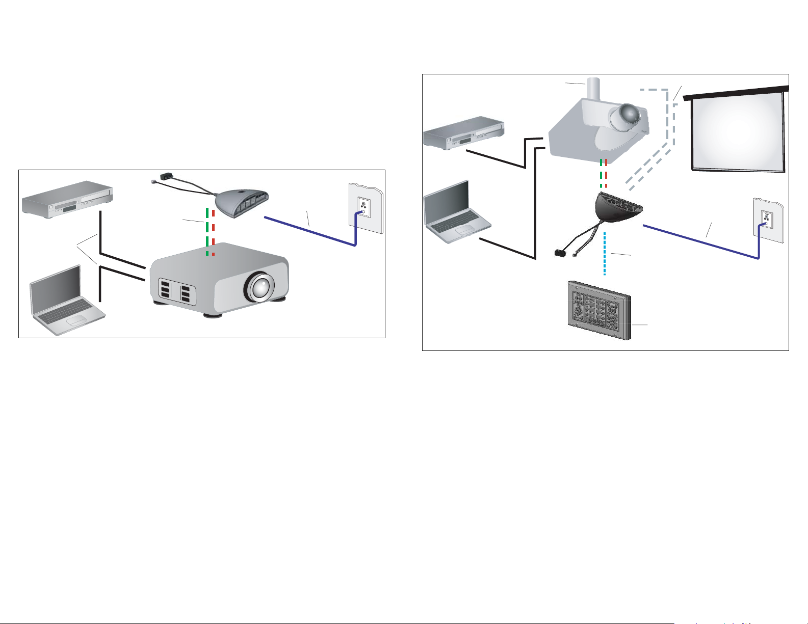
System 2: NRC and Modular Panel combined as control system for a projector, with
the relays on the NRC being used to control a lift and a screen.
As with Example 1, the NRC controls the projector with RS-232 and IR, it is on the network and it can
be controlled via the Web interface. Additionally, the Modular Panel in this example can be used for
in-room control. Also, the NRC’s low-voltage relays are used to raise and lower a screen and a lift.
II. Sample Systems
A few real-world examples of systems that the NRC can control will give you a clearer view of the
NRC’s capabilities. What follows are three examples of systems that could be controlled using the
NRC, Modular Panel, and Control Pucks in various configurations. (Note: these examples are not the
only possible set-ups; they're simply a few common types to help illustrate some of the things you can
do with the NRC family.)
System 1: NRC as stand-alone control device for a projector. NRC controls the
projector with RS-232 and IR.
The NRC can act as a stand-alone control device for rooms where you don't need a wall-mounted
controller. In this case the simplest possible set-up for the NRC — you'd have the NRC installed at
the projector and powered there. It will control the projector with RS-232 and IR (in this example, both
are used to control the projector, but some projectors will simply use one or the other). The NRC must
be connected to a local network or the Internet. To access its functions, use a Web browser that has
access to the same network that the NRC is on, and log in to the NRC to monitor, configure, and con-
trol it.
32
Video InVideo In
Video Signal
RS-232 and IR
Network
SP Bus
Relay Control
Automated Lift
Network
PX2-MP-IR
III. Getting Started
Configuring the NRC to Operate Without Network Control
Some users will wish to take advantage of the NRC control capabilities without using its network inter-
face. If this is what you wish to do, follow the first four steps of the configuration process described in
this section in order to connect your PC to the NRC for configuration. Then Proceed to Chapter IV.
Basic Configuration and configure the unit directly from your PC.
Important: If you do not plan to put your NRC online, you will need to download the NRC and Puck
drivers you need from our website before configuring the NRC:
http://www.spcontrols.com/downloads_index.php
The first time you connect for configuration, the NRC will automatically create the appropriate driver
directories on your hard drive. You can also add the new directory locations yourself :
NRC projector/monitor drivers: C:\~\My Documents\SP Controls\smartpanel\drivers
Puck RS-232 or IR drivers: C:\~\My Documents\SP Controls\nrc\drivers
10 steps to get the NRC online
Step 1: Get answers to these questions from your network administrator
• Will the NRC use a static IP address or DHCP?
• If the NRC will be using a static IP address, what will the IP address, subnet mask, gateway, pri-
mary DNS, and secondary DNS will be assigned to this NRC?
• If the NRC will be using DHCP, what IP address will be assigned by the DHCP server? You’ll need
to provide your network administrator with the MAC address from this NRC so he or she can assign a
unique IP address to it. The MAC address can be found under the ‘Network’ tab in the Configuration
section. (See Figure 3)
Step 2: Disable virus protection software and connect the NRC directly to
your computer
While configuring your NRC, all virus protection applications should be temporarily disabled. Virus
protection applications frequently manage your PC’s port settings in ways that can interfere with con-
figuration, though the exact nature of trouble can vary dramatically. Your browser may periodically dis-
connect from the NRC, you may be unable to upload settings, or configuration options may not work.
Most virus protection software can be disabled by right-clicking the software icon in the system tray of
your Windows
TM
Task Bar and selecting the appropriate option.
Power the NRC and connect its Ethernet port directly to your computer’s network port using a stan-
dard straight CAT5, CAT5e, or CAT6 cable with RJ-45 connectors.
Step 3: Change your computer’s network settings
(For Windows
TM
XP) Open the Control Panel on your computer, select “Network Connections,” then
“Local Area Connection.” Click on “Change settings of this connection”, and then “Internet Protocol
(TCP/IP)”, then “Properties.”
Be sure to write down your computer’s original network settings so you can revert them once
you’re finished with these first few steps.
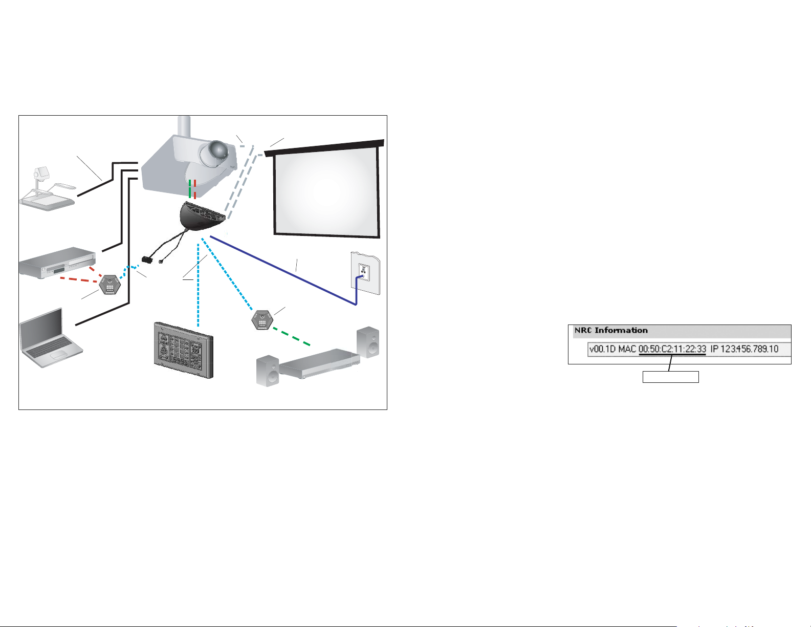
System 3:
NRC and Modular Panel combined to control a projector, with the relays on the NRC used for a
screen. It “listens” for contact closure on one of its sense ports, which triggers a theft warn-
ing email. An IR Puck controls a DVD player and a VCR. One RS-232/IR Puck controls an am-
plifier-receiver.
In this example, the NRC is the control center for several devices connected as a single system. As
shown in the image above, the NRC is mounted at the projector, controlling it with a combination of
RS-232 and IR. It controls a screen with low-voltage relays, and it is connected to a Modular Panel for
in-room control of the system. It is also connected to a network, so Web-based control is possible.
In this example, the NRC also sends commands to two Control Pucks. The first Puck has four IR
ports, two of which are used to control the DVD and VCR. The second Puck has one RS-232 port and
controls the amplifier with RS-232. One of the NRC sense ports is wired to a security loop such that if
the loop is broken, it will trigger the NRC to send an alert email to security staff.
IR Puck
(controls
combo unit
)
RS-232 Puck
(controls amp)
SP Bus
MAC address
5
Video
Network
Sense Port
(wired to security loop)
Control Relay
(screen control)
4
Step 6: DON’T PANIC!
As soon as you click Apply Changes, the NRC Configuration Wizard will disappear from your browser
window. This is supposed to happen. To continue configuration, access the Configuration Wizard with
your browser again, but instead of connecting to the NRC directly with an Ethernet cable, connect to it
over the network.
Note: If the NRC interface does not come up on your browser within 90 seconds or so, simply re-
enter the address of the NRC in your browser’s address bar and click enter to reconnect to the de-
vice.
Step 7: Change your computer’s network settings back to what they were
Change your computer’s Network Settings back to what they were (i.e. reverse what you did in Step
3). Disconnect the Ethernet cable from the NRC and reconnect your computer to the network it was
on.
Step 8: Connect to the NRC on the network
Connect the NRC to the same network your computer is on. If you chose a static IP, enter that IP ad-
dress into your web browser’s location field. If you chose DHCP, use the IP address that your network
administrator gave you. You’ll be prompted for login name and password again (remember: “Admin”
for both).
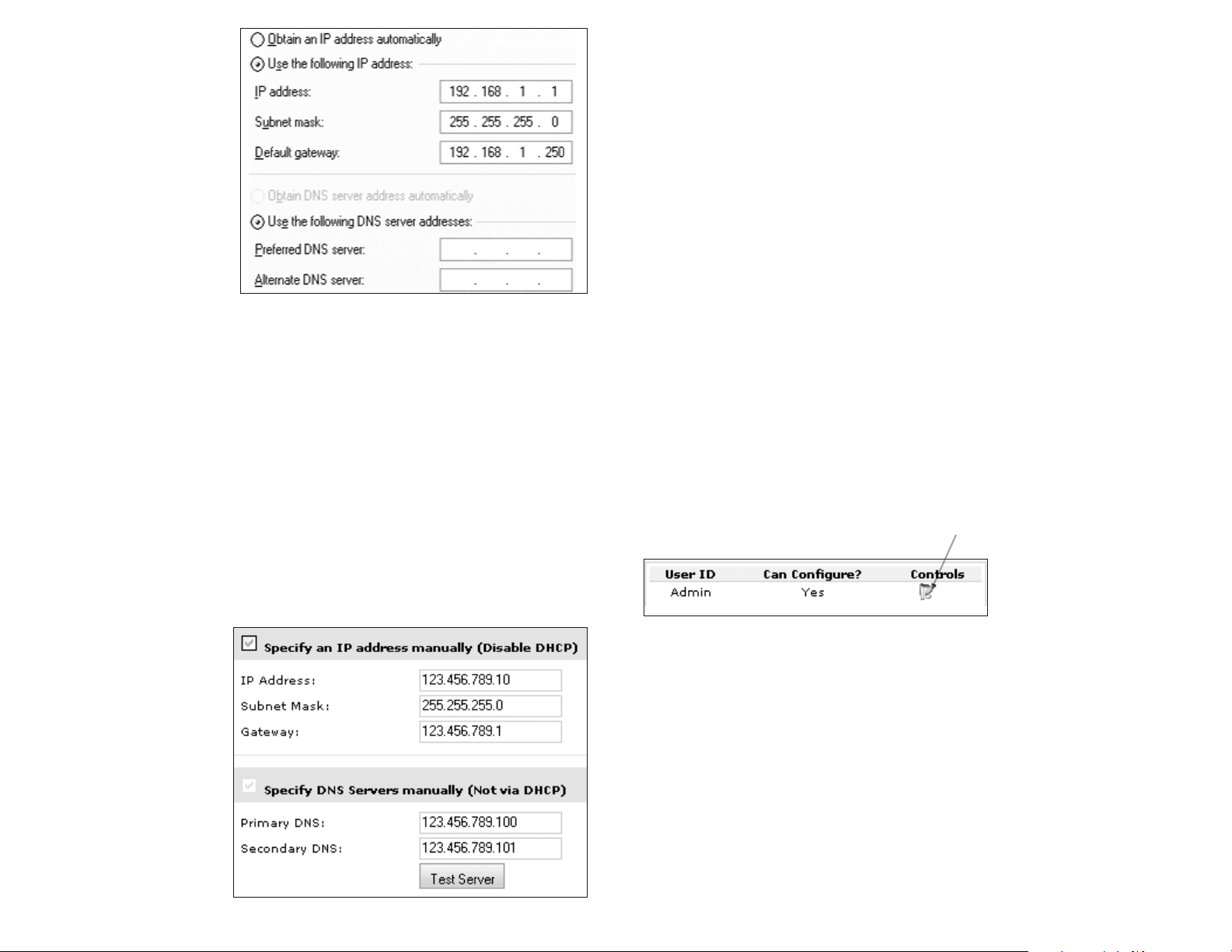
Step 9: Change the default password and add users
Now that your NRC is live on the network, you should change its default password to prevent unau-
thorized access. Be sure to record this password in a safe place! If you lose it, you will have to re-
vert your NRC back to its factory default settings and it will lose all its programming and configuration.
To change the password, click on Security, then on the pencil icon to edit the Admin user.
You may add other users at this time. To do so, simply click the Add + button. Then you’ll fill in the
UserID, Password, and Re-enter password fields for this user. UserID and password can be 3-16 al-
phanumeric characters in length (A-Z and 0-9 – no symbols allowed). Passwords are case sensitive.
You’ll also need to check the box labeled Can Configure if you want this user to be able to change the
configuration settings on the NRC, or leave it unchecked if you only want them to monitor and control.
The Admin user will always have configuration privileges.
Step 10: Your NRC is online!
You’re ready to start configuring your NRC to control the devices in your room.
7
Use the following IP settings:
IP address: 192.168.1.1
Subnet mask: 255.255.255.0
Default gateway: 192.168.1.250
DNS server fields can be left blank.
Save these settings and close the
windows.
Step 4: Open a Web browser
and connect to the NRC
Type the following URL into the
browser’s location bar:
http://192.168.1.100
You will be prompted for a username
and password; enter “Admin” into both
fields (username and password are case sensitive). After a few seconds, you should then see the
“Monitor and Control” page of the NRC.
If you are not configuring your NRC for network use, go to Chapter IV. Basic Configuration to continue
configuration.
Step 5: Configure the NRC’s network settings
Now that you can see the NRC in your browser, you need to configure its network settings. You’ll
need to follow one of the two instructions below, depending on whether you’ll be using a static IP ad-
dress or DHCP.
Assigning a static IP address
Mark the checkbox shown to the right, then enter the IP Address, Subnet Mask, Gateway, Primary
DNS, and Secondary DNS that you received from your network administrator. Once you’ve entered
this info, click Save Changes, then click Reboot NRC. Go to Step 6.
Assigning DHCP
To use DHCP, you’ll need to give
your network administrator the MAC
address for the NRC. Your network
administrator will need to ensure that
the NRC is assigned the same IP ad-
dress every time by the DHCP
server. They will need to give you the
IP address that the DHCP server will
assign. Uncheck both boxes that
indicate you want to specify IP ad-
dress and DNS servers manually to
enable DHCP. Click Save Changes,
and then click Reboot NRC. Go to
Step 6
.
6
Example of TCP/IP configuration window from inside
the Microsoft Windows
TM
XP Control Panel

IV. Basic Configuration
In simple rooms like “System 1” detailed in Chapter 2, the NRC will control only a single display de-
vice, a screen, and a lift, with a Modular Panel attached as the in-room control interface. This chapter
will help you configure the NRC to do just that. The NRC can control many more devices than just a
projector, which will be discussed in the next chapter, Advanced Configuration. Now click the De-
vices Setup link.
Start by entering the Room Name for this NRC. It’s a good idea to use a name that will make it easy
to identify its location, especially if you plan on monitoring and controlling several NRCs from one
computer. Then select one of the buttons below:
Load current NRC configuration: If you wish to change any settings on an NRC that has already been
configured, select this option. It will load the last settings saved to the NRC so you can make only the
changes you wish and keeping the other settings.
Resume the setup wizard where you last left off: If your configuration session is interrupted and you
have to exit the process, you may resume configuration by selecting this option. It will return you to
the last configuration page you completed.
Create a new setup: Select this option to begin a new configuration.
Copy settings from another NRC: Click this button to copy the room configuration from another NRC
that is already set up on your network. You will be prompted to enter the hostname or IP address of
the NRC you wish to copy from.
Read a saved setup template: Click this button if you’ve previously saved an NRC room configuration
file on your computer (these files are saved in C:\~\My Documents\SP Controls\nrc\userrooms). This
can be a convenient way to set up a room that will be identical to another room, especially if you don’t
currently have access to that other NRC on your network. You will be prompted to select the room
configuration file.
After you’ve chosen one of the options, click Next.
If you have not previously used this computer to configure an NRC, the first thing you should do (if
your NRC is connected to the Internet) is click the Update Display Drivers button. This will check the
SP Controls website and create (or update) the list of drivers in the “Available Devices” pane in this
window. (This feature will only work if your PC is currently connected to the Internet.) Then select the
appropriate driver to control your display from that list. If you don’t see it, call SP Controls’ tech sup-
port for help (877-367-8444 ext. 302). We will either find a driver from that list that will be compatible
with your display, or we will create one for you whenever possible free of charge.
By default, the “Available Devices” pane will only show the most recent version of any driver. Check
the “Show All Driver Versions” box if you want to see all versions, including older ones. You shouldn’t
need to use this option often, though, as the most current version of a driver is generally best.
Every display driver we publish will have an “Application Note” that goes along with it. The App Notes
will describe a number of important features about your installation, including the pinouts for the RS-
232 port on your display and which adapters to use, whether the driver uses RS-232 and/or IR to con-
trol the display, any special configuration settings that need to be adjusted on the display to work with
this driver, and other information pertinent to this projector or driver.
Other Attached Devices: Check these boxes to control a screen or lift with the NRC’s relays. In this
example, we’ll have both.
Display Power Sensing Options: Power Sensing is a feature the NRC uses to stay in sync with
your projector. If the projector is unplugged or turned off with its set-top buttons, the NRC will sense
that and show it on the web interface and by darkening its button lights. You can also have the NRC
trigger other events upon a Power Sensing failure (e.g., it could send an email out informing someone
of a possible projector theft).
The NRC has two ways of sensing the projector’s power state: with RS-232 queries and through the
use of a current sensor connected to the NRC’s Sense 2 port. If RS-232 power status queries are
supported by your display device, this will be the default option. If you don’t need this feature, though,
you can disable it by selecting “None”. Disabling power polling will prevent some NRC features from
working, such as lamp hour tracking and some of the security features.
Note: The availability of RS-232 power polling is indicated for each display device in the SP Controls
Application Note
9
8
 Loading...