

Spaun TP 216 Technical Advice [ml]
to our policy of continual technical improvement.
Specifications and design are subject to change due 104216/06.10
dispose it on designated public collection points.
Please, on the end of its life cycle, take this unit and
equipment, it should be disposed properly.
of January, 27th 2003 on used electrical and electronic
2002/96/EC) of the European Parliament and the Council
50419 (corresponds to the article 11(2) of the guideline
waste - in accordance with the European directive EN
Electrical and electronic equipment are not house-hold
Technische Hinweise
und Anwendungsbeispiele
für DiSEqC-Monitor TP 216
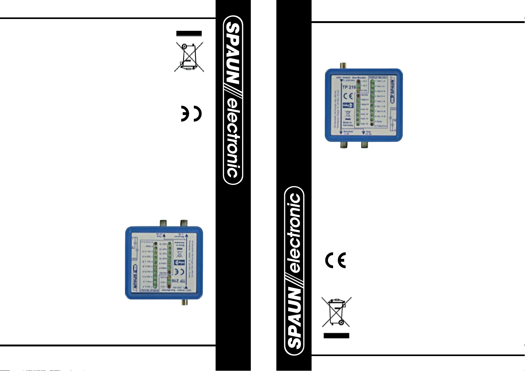
Beschreibung und Technische Daten:
Messtechnisches Prüfmittel zur
by the CE sign.
in accordance to the EU product norm EN 60728-11
EN 50083-2 and the keeping of the safety requirements
requirements in accordance to the EU product norm
SPAUN electronic confirms the keeping of the EMC
• Testsocket (-20 dB).
• Testpoints to measure remote current and voltage.
• LEDs to indicate hex addresses.
• LEDs to indicate reply and parity error (DiSEqC 2.0).
• LEDs to indicate vertical or horizontal selection and tone signal (22 kHz).
• LEDs to indicate DiSEqC selection (IF 1 ... 8, Option, Standby).
Remote supply: 10 ... 20 V DC / 70 mA
DC through path current: max. 600 mA
Through loss: max. 2 dB
Frequency range: 5 ... 2200 MHz
Telephone: +49 (0) 7731 - 8673-0 · Fax: +49 (0) 7731 - 8673-17
change using the test tool.
of the network do not
• Loads and terminations
in distribution networks.
systematic troubleshooting
Useful test tool to ease
Byk-Gulden-Str. 22 · D-78224 Singen
Email: contact@spaun.com · www.spaun.com
Byk-Gulden-Str. 22 · D-78224 Singen
Telefon: +49 (0) 7731 - 8673-0 · Telefax: +49 (0) 7731 - 8673-17
Unterstützung der systematischen
Fehlersuche in Verteilnetzen.
• Die Last- und Impendanzver hältnisse des Anlageaufbaues
bleiben unverändert.
E-Mail: info@spaun.de · www.spaun.de
Frequenzbereich: 5 ... 2200 MHz
Durchgangsdämpfung: max. 2 dB
DC-Durchlass: max. 600 mA
Strombedarf: 10 ... 20 V DC / 70 mA
• LEDs für DiSEqC-Funktionen (ZF 1 ... 8, Option, Standby).
• LEDs für Vertikal-, Horizontal- und Tonsignal (22 kHz).
• LEDs für Reply und Parity Error (DiSEqC 2.0).
• LEDs für Hex Adressen.
• Prüfbuchsen für Strom- und Spannungsmessung.
• Testbuchse (-20 dB) für HF-Schnelldiagnose.
Mit der CE-Kennzeichnung bestätigt SPAUN die
Einhaltung der EMV-Anforderungen entsprechend
der EU Produktnorm EN 60728-2 und die Einhaltung
der Sicherheitsanforderungen entsprechend der EU
Produktnorm EN 60728-11.
Description and Technical data:
for DiSEqC-Monitor TP 16
and Application diagrams
Technical Instructions
Elektronische Geräte gehören nicht in den Hausmüll,
sondern müssen - gemäß der Richtlinie DIN EN 50419
(entspricht dem Artikel 11(2) der Richtlinie 2002/96/EG) des
Europäischen Parlaments und des Rates vom 27. Januar
2003 über Elektro- und Elektronik -Altgeräte - fachgerecht
entsorgt werden. Bitte geben Sie dieses Gerät am Ende
seiner Verwendung zur Entsorgung an den dafür vorgesehenen öffentlichen Sammelstellen ab.
Technische Verbesserungen, Änderungen im Design und Irrtümer vorbehalten. 104216/06.10
Prüfen der
Receiver-Schaltkriterien:
Bus-Monitor:
LED rot: Fernspeisespannung < 15 V
LED grün: Fernspeisespannung > 15 V
LED gelb: Tonsignal ( 22 kHz )
DiSEqC-Monitor:
LEDs 1 ... 8 : Anzeige der
gewählten ZF-Ebene
LEDs Option A / Option B:
Anzeige
des optionalen
Schaltkriteriums
LED Standby: Anzeige der
DiSEqC Standby-Funktion
Test of the
Receiver control signals:
Bus-Monitor:
LED red: remote voltage < 15 V
LED green: remote voltage > 15 V
LED yellow: tone signal ( 22 kHz )
DiSEqC-Monitor:
LEDs 1 ... 8: indicate the
selected IF-Signal
LEDs Option A / Option B:
indicate
the optional
control signal
LED Standby: indication of
the DiSEqC standby mode
1
SUR 211 F
TP 216
Schalterstellung Option
Option mode
SUR 211 F
TP 216
Schalterstellung Option
Option mode
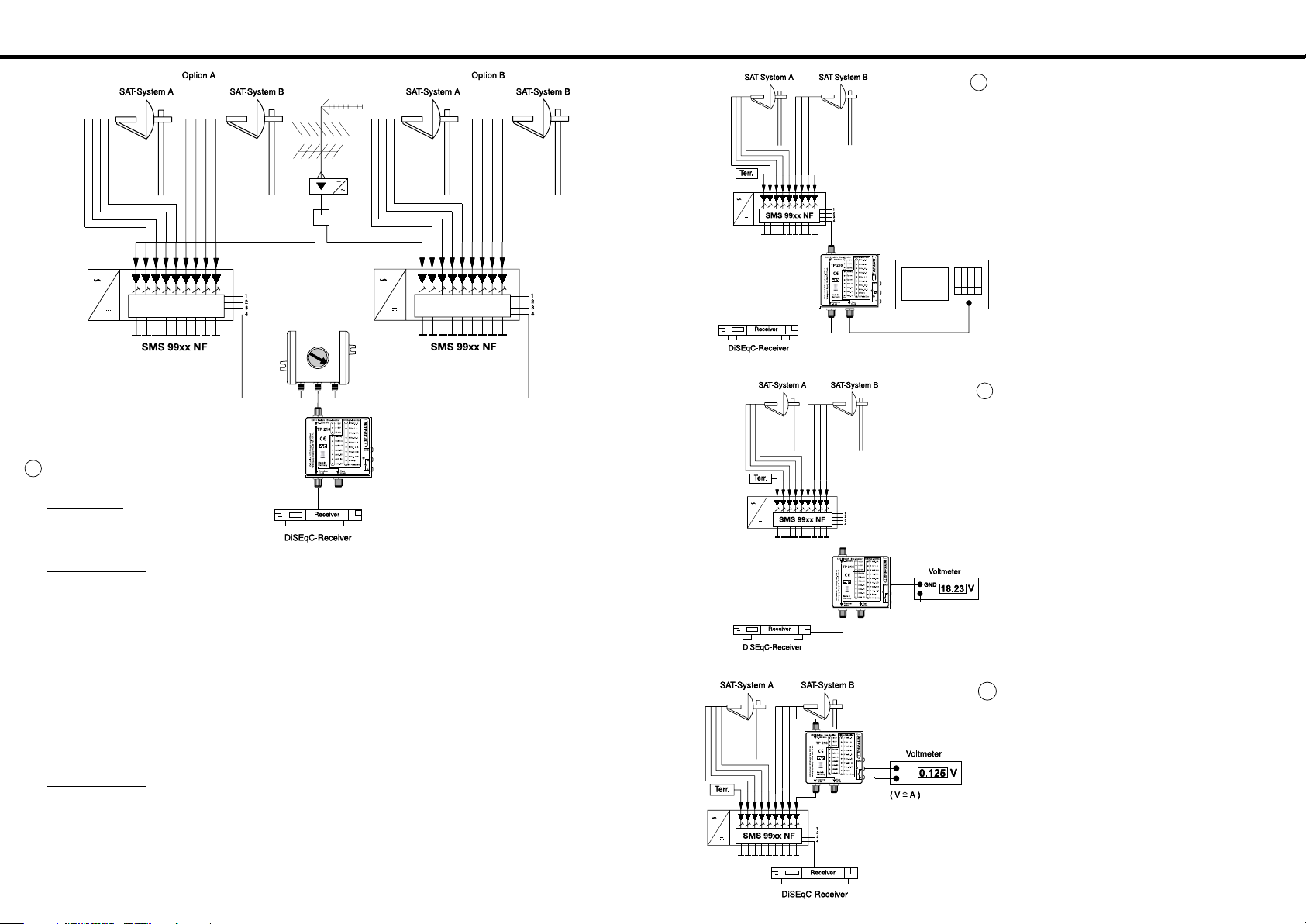
Messen des HF-Pegels:
- Antennenmessgerät mit HF-Testpunkt verbinden.
- HF-Testbuchse ist DC-frei
Anzeigewert + 20 dB = HF-Pegel auf Koaxialleitung
Measuring of RF-level:
- Connect levelmeter to RF-Testpoint
( Port is DC-free ).
level = value + 20 dB
2
TP 216
Antennenmessgerät
Spannungsmessung:
- Plusleitung des Voltmeters in “+” Prüfbuchse.
- Masse ( COM bzw. GND ) in die “GND”-Prüfbuchse.
Voltage measuring:
- Connect plus wire from voltmeter to “+” testpoint.
- Connect COMMON-wire from voltmeter to “GND”-
testpoint.
3
TP 216
Strommessung:
( Messart: Indirekt über Shuntwiderstand 1 Ohm )
- Voltmeter mit den beiden unteren Prüfbuchsen
verbinden.
- Voltmeter in 2-Voltbereich schalten.
- Anzeigewert in Ampere ablesen.
Current measuring:
( Measured via 1 Ohm shunt )
- Connect voltmeter to the lower testpoints.
- Select the 2 volt range.
- Read value in ampere.
4
TP 216
Reply:
LED grün: Rückmeldung von
DiSEqC 2.0 Komponenten
Parity Error
LED rot: signalisiert fehlerhafte
Übertragungsdaten
Addr. 18 SMATV
Addr. 15 Relais (DC Through)
Addr. 14 Multischalter (DC blocking)
Addr. 10 Universal
Wenn alle Adress LED´s grün leuchten
wird die Universal Adresse 00 gesendet,
d.h. Befehl vom Master an alle DiSEqCfähigen Komponenten. Receiver senden
meistens Addr. 10 oder Addr. 00 (Universal).
Reply:
LED green: reply of DiSEqC 2.0
components
Parity Error
LED red: wrong DiSEqC data
are signalised.
Addr. 18 SMATV
Addr. 15 Relais (DC Through)
Addr. 14 Multiswitch (DC blocking)
Addr. 10 Universal
All address LED´s green has the meaning
universal DiSEqC adress 00 or Master to
all devices. Normally the receivers are
sending Addr. 10 or Addr. 00 (universal).
 Loading...