

Page 1
Mit der CE-Kennzeichnung bestätigt SPAUN die
Einhaltung der EMV-Anforderungen entsprechend
der EU Produktnorm EN 50083-2 und die Einhaltung
der Sicherheitsanforderungen entsprechend der EU
Produktnorm EN 50083-1.
Die Multischalter erfüllen die erhöhten Schirmungsmaß-Anforderungen gemäß EN 50083-2, Güteklasse A.
Alle Komponenten sind zum Verbinden mit dem
Hauptpotentialausgleich mit einer Erdungsklemme
ausgestattet.
Die Multischalter unterstützen DiSEqC 2.0; das heißt:
Sie unterstützen die bidirektionale Kommunikation
zwischen Receiver und Multischalter.
Wichtig: alle nachfolgenden Hinweise
vollständig durchlesen und beachten.
• Die beschriebenen Geräte dienen ausschließlich der
Verwendung in Satelliten-Empfangsanlagen.
• Jegliche anderweitige Nutzung oder die Nichtbeachtung dieses Anwendungshinweises hat den Verlust
der Gewährleistung bzw. Garantie zur Folge.
• Die Geräte dürfen nur in trockenen Innenräumen
montiert werden. Nicht auf oder an leicht entzündlichen Materialien montieren.
• Die Geräte sind mit einer Potenzial-Ausgleichsleitung (Cu, mindestens 4 mm
2
) zu versehen.
• Die Sicherheitsbestimmungen nach EN 50083-1
und EN 60065 A11 sind zu beachten.
• Befestigungsmittel: Schraubkupplung 75 (Serie F)
nach IEC 60169.
• Nicht benutzte Teilnehmer-/ Stammleitungsausgänge
sind mit 75-Ohm-Widerständen abzuschließen.
Technische Verbesserungen, Änderungen im Design und Irrtümer vorbehalten. 104987 /02.07
Technische Hinweise
zum SAT-ZF-Multischalter SMS 9987 U
und
zu dem Relais SMR 9210 F
Der terrestrische Eingang des Multischalters ist auch
für die Einspeisung digitaler Fernsehsignale geeignet.
-T
Page 2
2
TM
Elektronische Geräte gehören nicht in den Hausmüll, sondern müssen gemäß der Richtlinie DIN EN 50419 (entspricht dem Artikel 11(2) der
Richtlinie 2002/96/EG) des Europäischen Parlaments und des Rates vom
27. Januar 2003 über Elektro- und Elektronik-Altgeräte- fachgerecht entsorgt werden. Bitte, geben Sie dieses Gerät am Ende seiner Verwendung
zur Entsorgung an den dafür vorgesehenen öffentlichen Sammelstellen ab.
Die zulässige Umgebungstemperatur beträgt: -20° C ... +50° C.
Unisystem Multischalter SMS 9987 U
Einsetzbar als:
Multischalter zur Verteilung von 8 SAT-ZF Ebenen und terrestrischer Signale. Universell
einsetzbar als Einzelbaustein für 8 Teilnehmer oder als kaskadierbarer Multischalter
(Empfehlung maximal 24 Teilnehmer / Receiver).
In Sandwich Bauweise als Erweiterungskomponente zum Empfang und zur Verteilung
von 8 oder 16 SAT-ZF-Ebenen.
➞ siehe Kapitel “Montagehinweise”.
Versorgung:
Das UniSystem findet dort seinen Einsatz, wo kein Netzanschluss vorhanden ist. Die
Versorgung des Systems erfolgt durch die angeschlossenen Receiver der Teilnehmer.
Bei Nutzung des Systems durch lediglich einen Teilnehmer / Receiver ist ein Strombedarf von max. 320 mA erforderlich. Bei zu geringer Stromabgabe des angeschlossenen Receivers ist optional ein Netzteil (Spaun SN 18/600) am terr. Stammausgang
anzuschließen.
LNB-Typ:
Die LNB-Eingänge des Multischalters SMS 9987 U sind für eine 12 V-Betriebsspannung
ausgelegt. Daher ist der Einsatz eines SMATV / Quatro-LNB´s neuester Generation
zwingend notwendig.
Umschaltlogik:
Die Wahl der SAT-ZF-Ebenen erfolgt mit den Schaltkriterien 14 V / 18 V und/oder
0 / 22 kHz und/oder ToneBurst oder mit DiSEqC-Befehlen.
Terrestrik (5...862 MHz):
Die Terrestrik wird im Multischalter passiv durchgeleitet. Die Durchgangsdämpfung beträgt
4,5 dB, die Abzweigdämpfung pro Teilnehmerausgang beträgt 27,5 dB.
Terrestrische Antennensignale sollten dem Multischalter (-System) zur Vermeidung
von Störungen selektiv zugeführt werden.
Page 3
3
SAT-ZF (950...2200 MHz):
Der maximale Eingangspegel beträgt 85 dBµV bei Transpondervollbelegung.
Die SAT-ZF-Signale sind dem Multischalter entsprechend der Beschriftung zuzuführen,
damit die logische Zuordnung der ZF-Ebenen gemäß den Umschaltkriterien stimmt.
• Teilnehmerausgänge A ... H / Abzweigdämpfung:
zwecks Neutralisierung der internen Verteilverluste ist im SMS 9987 U für jeden
Teilnehmerausgang eine Verstärkerstufe integriert, die eine Abzweigdämpfung
von je 3 ... +1 dB bewirkt.
Der max. Ausgangspegel für die SAT-ZF an den Teilnehmerausgängen A ... H
beträgt 86 dBµV.
´´
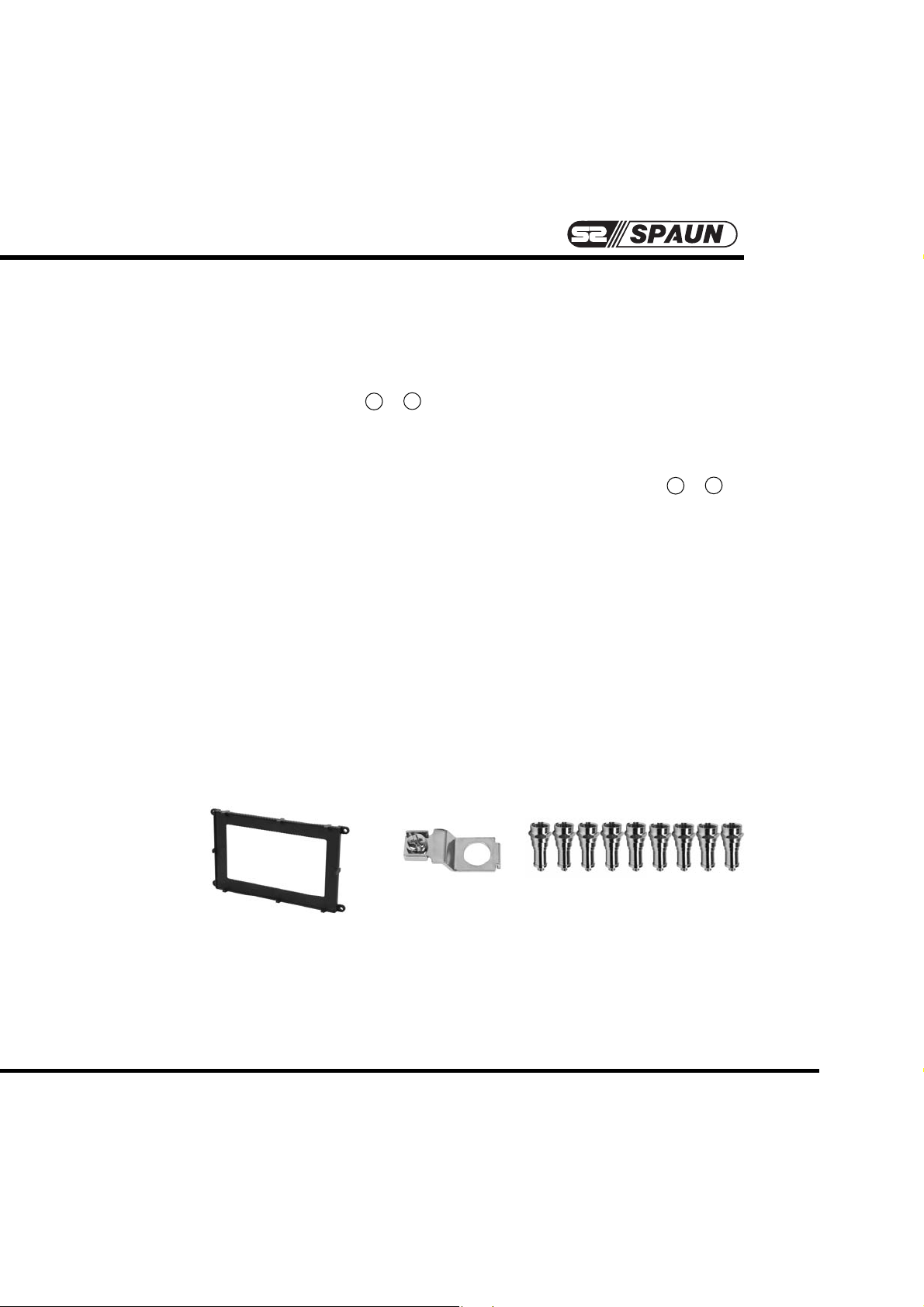
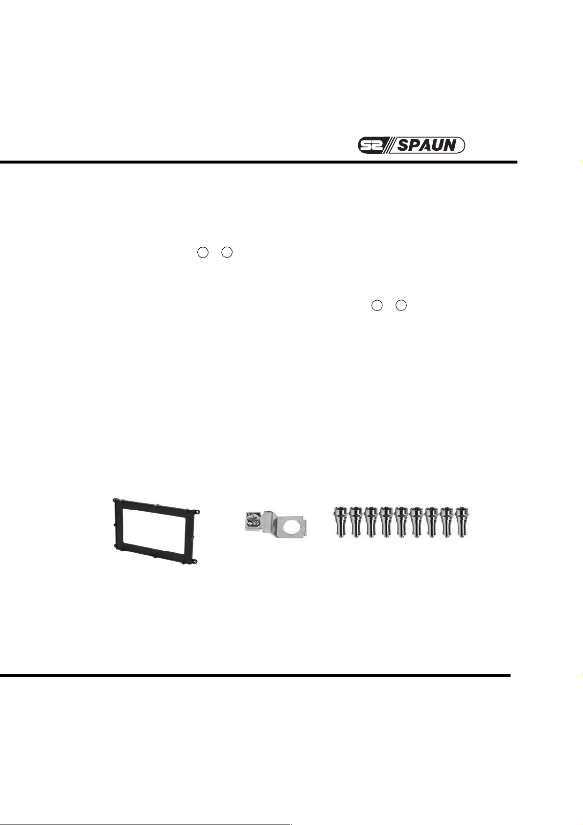
Lieferumfang:
Dem Multischalter SMS 9987 U sind beigefügt:
1. ein Befestigungsrahmen für Wand- und Sandwich Montage bei Erweiterung des
Systems auf 16 SAT-ZF-Ebenen
2. Erdungsklemme.
3. neun DC-entkoppelte Abschlusswiderstände ZFR 75 DC zum
Abschließen der Stammleitungsausgänge.
1. 2. 3.
TM
Page 4
4
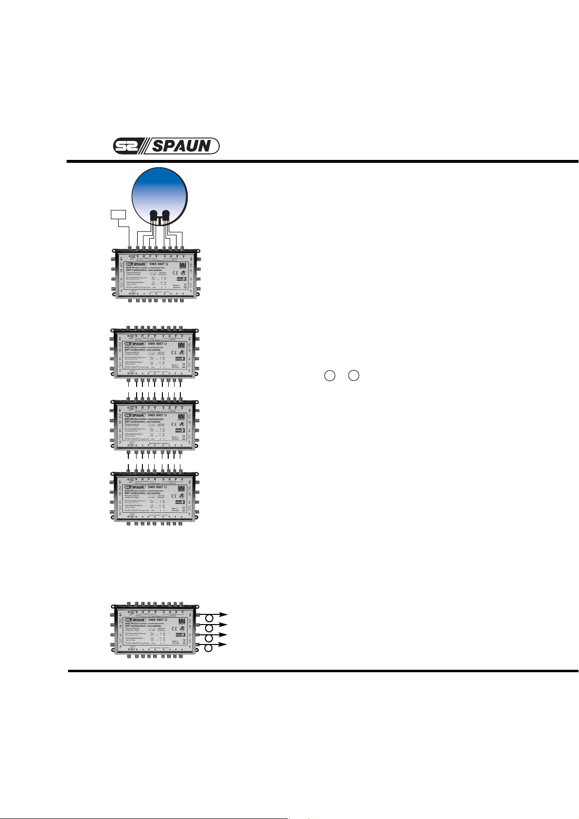
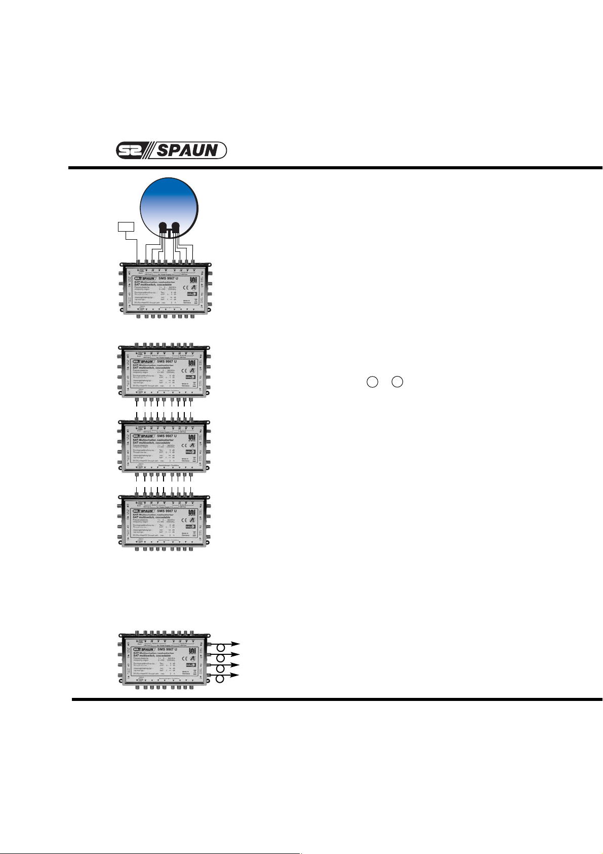
Montagehinweise:
1. Empfang von 2 SAT-Systemen
mit 8 SAT-ZF-Ebenen und Terrestrik:
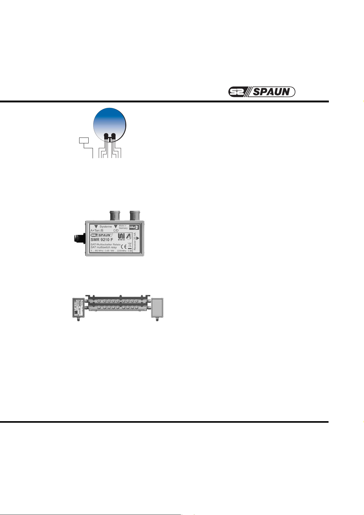
1.1 Einsatz des SMS 9987 U als Einzelgerät für 8 Teilnehmer
Verwendung als “9 in 8”:
1.1.1 Multischalter in den Befestigungsrahmen einklipsen.
1.1.2 Ausgänge des LNBs mit den SAT-ZF-Eingängen
- entsprechend der Beschriftung des Multischalters verbinden.
1.1.3 Terr. Signale (sofern vorhanden) zuführen.
(Bei Nichtbenutzung mit 75 Ohm abschließen ! )
1.1.4 Teilnehmerausgänge A ... H herstellen.
(Reserve berücksichtigen ➞ siehe “Generelle Empfehlung”)
1.1.5 Stammleitungsausgänge mit den beigelegten Abschlusswiderständen DC-entkoppelt abschließen.
1.2 Einsatz des SMS 9987 U in der Kaskade für
16 ... bis max. 24 Teilnehmer.
Die Multischalter können bei zentraler Verteilung untereinander mit den Schnellverbindungssteckern ZSV 2 S
direkt verbunden oder auch als “Etagenverteiler” installiert werden. Stammleitungsausgänge des zuletzt montierten Multischalters DC-entkoppelt abschließen.
Generelle Empfehlung:
Berücksichtigen Sie, dass dieses System ggf. zu einem späteren Zeitpunkt zum Empfang
weiterer SAT-Systeme ausgebaut werden soll !
Alle Teilnehmerleitungen sollten Sie mit einer “Reserve”
von ca. 20 cm verlegen, um den nachträglichen Bedarf/
Einsatz von Multischalter-Relais SMR ... problemlos
realisieren zu können.
T
T
T
T
T
T
T
T
T
T
T
T
T
T
T
T
T
T
Terr.
TM
Page 5
5
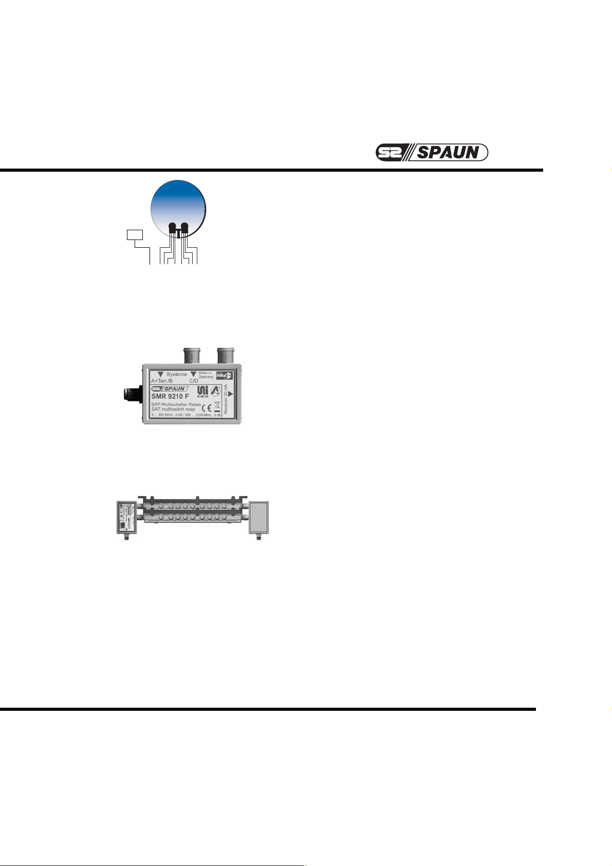
Montagehinweise:
2. Empfang von 4 SAT-Systemen
mit 16 SAT-ZF-Ebenen und Terrestrik:
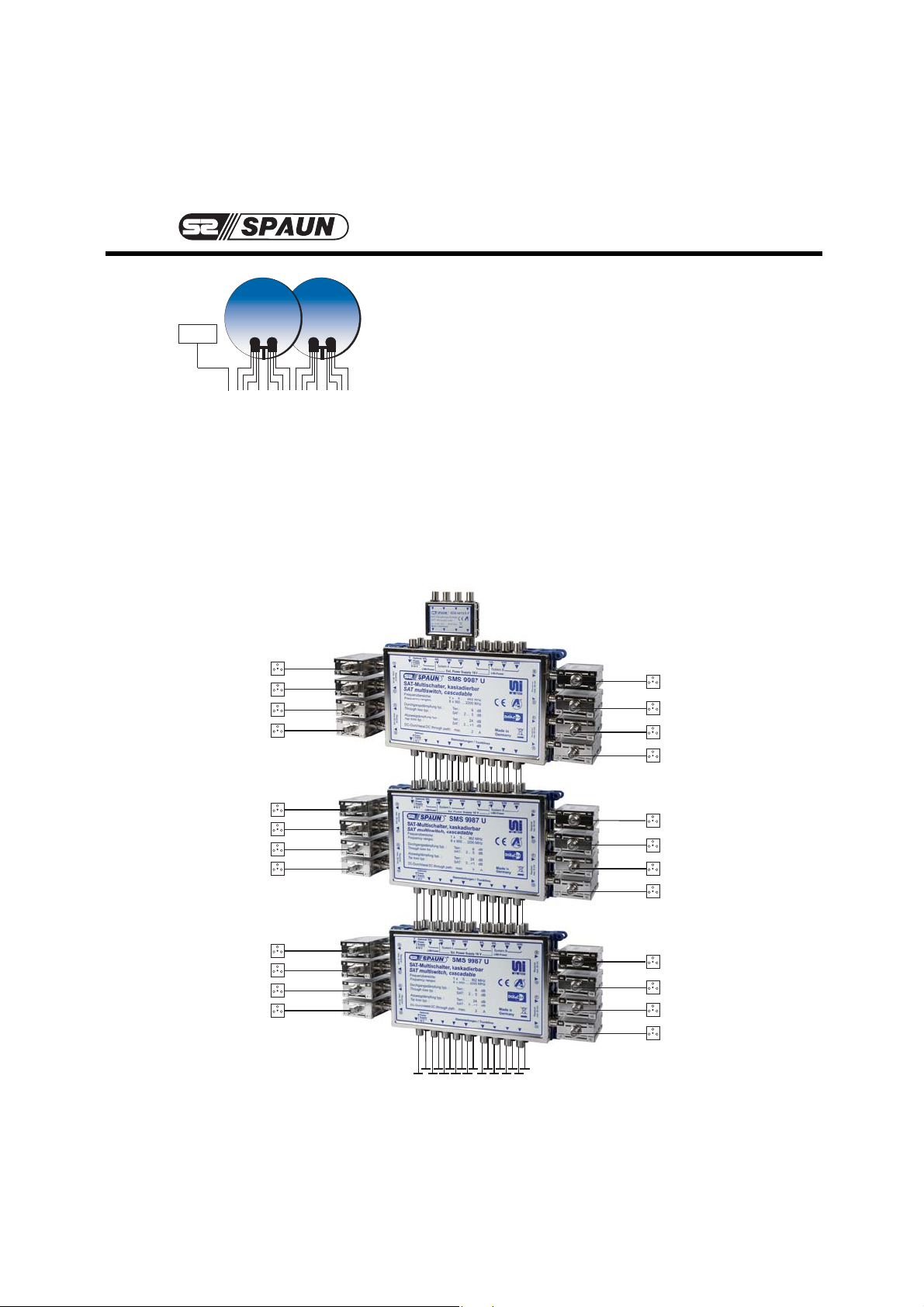
2.1 Für jeweils 8 Teilnehmer / Receiver kommen
2 Multischalter SMS 9987 U sowie 8 Multischalter-Relais SMR 9210 F zum Einsatz.
2.1.1 Zunächst Multischalter SMS 9987 U für die
SAT-Systeme A und B (Wandmontage)
montieren.
2.1.2 Alle Anschlüsse herstellen (siehe Seite 4,
Punkte 1.1.1 bis ggf. 1.2).
2.1.3 Multischalter für die SAT-Systeme A und B
einpegeln. (siehe auch Seite 6, Punkte
3.1 - 3.2)
2.1.4 Nächsten Rahmen auf den montierten
Multischalter SMS 9987 U - zwecks darauf
folgender Befestigung der Komponenten für
die SAT-Systeme C und D - aufklipsen.
2.1.5 Nach erfolgter “Sandwich”-Montage sind
die Ausgänge des Quatro-LNBs mit den
Eingängen des Multischalters für die
SAT-Systeme C und D - entsprechend der
Beschriftung - zu verbinden.
2.1.6 Der terrestrische Ein- und Ausgang des
zweiten Multischalters ist mit DC-entkoppelten Abschlusswiderständen ZFR 75 DC
abzuschließen !
2.1.7 Multischalter für SAT-Systeme C und D
einpegeln.(siehe auch Seite 6, Punkte
3.1 - 3.2)
2.1.8 Die Teilnehmerausgänge der beiden Multischalter werden durch Aufstecken der Multischalter-Relais SMR 9210 F zusammengeführt.
Nach Verbinden der Teilnehmerleitungen mit
den Receivern ist die Programmauswahl aus
16 SAT-ZF-Ebenen möglich.
2.2 Einsatz des Multischalter-Systems in der
Kaskade für 16 ... bis max. 24 Teilnehmer
(siehe Seite 4, Punkt 1.2).
Terr.
TM
Page 6
6
TM
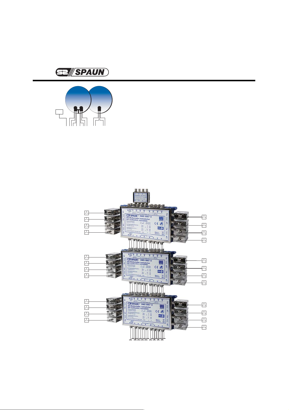
Montagehinweise:
3. Einpegelung der SAT-Systeme A/B und C/D
mit der SAT-Dämpfungs-Einheit SDE 4415/5 F
(Artikel-Nummer 871319)
3.1 Die SAT-Dämpfungs-Einheit SDE 4415/5 F dient
zum An- bzw. Ausgleichen unterschiedlicher
Signale zwischen SAT-Systemen. Die Einheit ist
direkt aufsteckbar auf die Eingangsbuchsen der
SAT-Systeme A / B und C / D der Multischalter
SMS 9987 U. Dämpfung ist 5 dB fix.
3.2 Die Messung der Signalstärke der einzelnen
SAT-Systeme ist Voraussetzung für den korrekten
Einsatz der SAT-Dämpfungs-Einheit SDE 4415/5 F.
Anwendungsgebiete sind zu hohe Pegel über 85
dBµV (siehe Seite 3) oder Pegelunterschiede über
5 dB zwischen den SAT-Systemen A/B oder C/D.
Terr.
SDE 4415/5 F
Page 7
Technical advice
for the SMS 9987 U multiswitch
and
the SMR 9210 F relay
SPAUN electronic confirms the keeping of the EMC
requirements in accordance to the EU product norm
EN 50083-2 and the keeping of the safety requirements
in accordance to the EU product norm EN 50083-1 by
the CE sign.
The multiswitches meet the more stringent screening
requirements according to EN 50083-2, quality grade A.
All components are equipped with an earthing
terminal for connecting to the main potential
equalization.
Specifications and design are subject to change due to our policy of continual technical improvement.
104987/02.07
Important: please observe the following
instructions !
• The equipment described is designed solely for the
installation of satellite receiver systems.
• Any other use, or failure to comply with these instructions, will result in voiding of warranty cover.
• The equipment may only be installed in dry indoor
areas. Do not mount on or against highly combustible materials.
• The safety regulations in accordance with EN 50083-1
and EN 60065 A 11 must be observed.
• Fixings: Wood screws, max 쏗: 4,5 mm
• Connector: screwed joint 75 ⏲ (series F) according to
IEC 60169.
• Unused subscriber and trunk connections should be
terminated by 75 Ohm resistors (e.g. ZFR 75 DC).
The multiswitches support DiSEqC level 2.0 Bi-directional
communication between receiver and multiswitch is
possible.
The terrestrial entrance of the multiswitch is suitable also
for the feed of digital television signals.
-T
Page 8
TM
The permissible ambient temperature range is:
-20° C ... +50° C (253 K ... 323 K).
Multiswitch SMS 9987 U:
The multiswitch for 8 SAT IF signals and passive terrestrial is universally applicable, for
example:
➞➞
As an individual device for 8 receivers,
➞➞
As a cascadable multiswitch for an additional 8 receivers each (max. 24 receivers),
➞➞
In a "sandwich" configuration as an add-on component to receive and distribute
16 SAT IF signals.
➞➞
See section "Assembly instructions".
Power supply:
The UniSystem can be used where there is no mains supply. The system is powered by
the connected receivers. If the system is only being used by one receiver, a maximum
power supply of 320 mA is required.
LNB type:
The LNB inputs of the SMS 9987 U multiswitch are designed for an operating voltage
of 12 V. This means that a new-generation SMATV / Quatro LNB must be used under
all circumstances. If the current output from the receiver is not sufficently, you have to
install the SPAUN power supply SN18/600 at the terrestrial output.
Switching logic:
The SAT IF signals are selected with switching criteria 14 V / 18 V and/or 0 / 22 kHz
and tone burst or with DiSEqC commands from the receiver.
Terrestrial (5...862 MHz):
The terrestrial is routed passively in the multiswitch and is return path compatible.
Through loss is 4,5 dB; tap loss per receiver output is 27 dB.
Terrestrial antenna signals should be fed selectively to the multiswitch (system) in
order to avoid malfunctions.
2
Electrical and electronic equipment are not household waste - in accordance with the European directive EN 50419 (corresponds to the article
11(2) of the guideline 2002/96/EC) of the European Parliament and the
Council of January, 27th 2003 on used electrical and electronic equipment, it should be disposed properly.
Please, on the end of its life cycle, take this unit and dispose it on designated public collection points.
Page 9
SAT IF (950...2200 MHz):
The maximum input level is 85 dBµV at full transponder utilisation.
The SAT IF signals are to be fed to the multiswitch according to the label so that
the logical allocation of IF signals is correct in line with the switching criteria.
• Receiver outputs A ... H / tap loss:
In order to neutralise internal distribution loss, an amplifier level is integrated into
the SMS 9987 U for every receiver output.
This results in 3 ... +1 dB tap loss.
The maximum output level for the SAT IF to receiver outputs A ... H is 86 dBµV.
Scope of delivery:
The SMS 9987 U multiswitch comes with:
1. A mounting frame for wall and "sandwich" assembly for a system upgrade to
16 SAT IF signals
2. Earthing clamp.
3. Nine DC-isolated ZFR 75 DC terminating resistors to terminate the trunkline outputs.
1. 2. 3.
3
TM
Page 10
4
Assembly instructions:
1. Receiving a SAT system with 8 SAT IF signals
and terrestrial:
1.1 Using the SMS 9987 U as a standalone device
for 8 receivers; "9 in 8" use:
1.1.1 Clip the multiswitch into the mounting frame.
1.1.2 Connect the outputs of the Quatro LNB with the
SAT IF inputs in line with the multiswitch's label.
1.1.3 Feed terrestrial signals (if available).
(If not being used, terminate with 75 Ohm !)
1.1.4 Establish receiver outputs A ... H .
(Please refer our note below).
1.1.5 Terminate trunk line outputs with the DC-isolated
terminating resistors included in delivery.
1.2 Using the SMS 9987 U in a cascade configuration
for 16, max. 24 receivers:
With central distribution it is possible to connect
the multiswitches directly with one another using
ZSV 2 S quick plug connectors. They can also be
installed as "floor distributors". Terminate the trunkline outputs of the last multiswitch with DC-isolated
terminating resistors.
General recommendation:
Please note that this system may be extended to receive additional SAT systems
at a later point in time.
Note:
You should leave all receiver cables an extra
20 cm so that is possible to implement ad-
ditional SMR 9210 F multiswitch relays later if
necessary without any problems.
T
T
T
T
T
T
T
T
T
T
T
T
T
T
T
T
T
T
Terr.
TM
Page 11
5
Assembly instructions:
2. Receiving 4 SAT systems with 16 SAT IF
signals and terrestrial:
2.1 Two SMS 9987 U multiswitches and eight
SMR 9210 F multiswitch relays are used
for every eight receivers.
2.1.1 First mount the SMS 9987 U multiswitch
for SAT system A and B (wall assembly).
2.1.2 Establish all connections (see page 4,
point 1.1.1 to 1.2 as necessary).
2.1.3 Carry out level adjustment on the
SAT system A and B multiswitch.
(Please refer page 6, point 3.1. to 3.2).
2.1.4 Clip the frame onto the mounted
SMS 9987 U multiswitch for subsequent
mounting of SAT system C and D
components.
2.1.5 After you have successfully completed
the "sandwich" assembly, connect the
outputs of the Quatro LNB with the inputs
of the SAT system C and D multiswitch.
2.1.6 Terminate the terrestrial input and output of
the second multiswitch with DC-isolated
ZFR 75 DC terminating resistors.
2.1.7 Carry out level adjustment on the SAT
system C and D multiswitch.
(Please refer page 6, point 3.1. to 3.2).
2.1.8 Receiver outputs of both multiswitches
are combined by attaching the SMR 9210 F
multiswitch relays. Once the receiver cables
have been connected to the receivers,
program selection is possible from 16 SAT IF
signals.
2.2 Using the multiswitch system in a cascade
configuration for 16, max. 24 receivers
(see page 4, point 1.2).
Terr.
TM
Page 12
6
Assembly instructions:
3. Adjusting the SAT-Systems A / B and C / D
with SAT attenuator unit SDE 4415/5 F
(Order No. 871319)
3.1 The SAT attenuator unit SDE 4415/5 F can be used
for adjusting / balancing different signals between
the satellite systems. The unit can be attached directly onto the input of SAT system A or B and
C or D of the multiswitch SMS 9987 U.
The loss value is fixed 5 dB.
3.2 The usage of the SAT attenuator SDE 4415/5 F
depends on the incoming level of the satellite
signals. If the level is higher than 85 dBµV (please
refer page 3), you should use the SAT attenuator
SDE 4415/5 F. Also you should use the unit, if the
difference between the two satellite systems A / B
or C / D is higher than 5 dB.
Terr.
SDE 4415/5 F
TM
 Loading...