

Spaun SMR 210 F, SMR 410 F Technical Advice [ml]

Technical Instructions
for the SMS 55xx UI Multiswitch
and
the SMR 210 F / SMR 410 F Relay
Email: contact@spaun.com · www.spaun.com
Byk-Gulden-Str. 22 · D-78224 Singen
Telephone: +49 (0) 7731 - 8673-0 · Telefax: +49 (0) 7731 - 8673-17
Important: please observe the following
instructions!
• The equipment described is designed solely for the
installation of satellite receiver systems.
• Any other use, or failure to comply with these instruc tions, will result in voiding of warranty cover.
• The equipment may only be installed in dry indoor
areas. Do not mount on or against highly combus tible materials.
• The safety regulations set out in the current
EN 60728-11 and EN 60065 standards must be
complied with.
• Fixings: Wood screws, max
• Connector: Screw coupling 75
EN 61169-24.
• Unused subscriber and trunk connections should
be closed off by DC decoupled 75 Ohm resistors
(e.g. ZFR 75 DC).
: 4,5 mm
(series F) to
SPAUN electronic confirms the keeping of the EMC
requirements in accordance to the EU product norm
EN 50083-2 and the keeping of the safety requirements
in accordance to the EU product norm EN 60728-11 by
the CE sign.
The multiswitches meet the more stringent screening
requirements according to EN 50083-2, quality grade A.
All components are equipped with an earthing
terminal for connecting to the main potential
equalization.
Electrical and electronic equipment are not house-
hold waste - in accordance with the European
directive EN 50419 (corresponds to the article 11(2)
of the guideline 2002/96/EC) of the European Parliament and the Council of January, 27th 2003 on
used electrical and electronic equipment, it should
be disposed properly. Please, on the end of its life
cycle, take this unit and dispose it on designated
public collection points.
Specifications and design are subject to change due to our policy of continual technical improvement.
104547/09.10
TM
The permissible ambient temperature range is:
-20° C ... +50° C (253 K ... 323 K).
Multiswitch SMS 55xx UI:
The multiswitch for 4 SAT IF signals and passive terrestrial is universally applicable, for
example:
➞ As an individual device for 4 receivers, SMS 5547 UI
➞ As an individual device for 8 receivers, SMS 5587 UI
➞ As a cascadable multiswitch for an additional 4/8 receivers each (max. 24 receivers)
➞ In a "sandwich" configuration as an add-on component to receive and distribute
8, 12 or 16 SAT IF signals
Power supply:
The UniSystem can be used where there is no mains supply. The system is powered by
the connected receivers. If the system is only being used by one receiver, a maximum
power supply of 80 mA + LNB is required.
LNB type:
The LNB inputs of the SMS 55xx UI multiswitch are designed for an operating voltage
of 12 V. This means that only Quattro LNB can be used under all circumstances. If the
current output from the receiver is not sufficently, you have to install the SPAUN power
supply SN18/600 or SNG 18/1000 at the terrestrial Output / Input.
Switching logic:
The SAT IF signals are selected with switching criteria 14 V / 18 V and/or 0 / 22 kHz.
Terrestrial (5...862 MHz):
The terrestrial is routed passively in the multiswitch and is return path compatible.
Through loss is typ. 4,5 dB; tap loss per receiver output is typ. 16 dB (SMS 5547 UI)
and 20 dB (SMS 5587 UI).
Terrestrial antenna signals must be fed selectively to the multiswitch in order to avoid
malfunctions.
2
TM
SAT IF (950...2200 MHz):
The SAT IF signals are to be fed to the multiswitch according to the label so that
the logical allocation of IF signals is correct in line with the switching criteria.
• Receiver outputs A ... H / tap loss:
In order to neutralise internal distribution loss, an amplifier level is integrated into
the SMS 55xx UI for every receiver output.
This results in a tap loss from
-1 ... 4 dB (SMS 5547 UI)
-2 ... 3 dB (SMS 5587 UI).
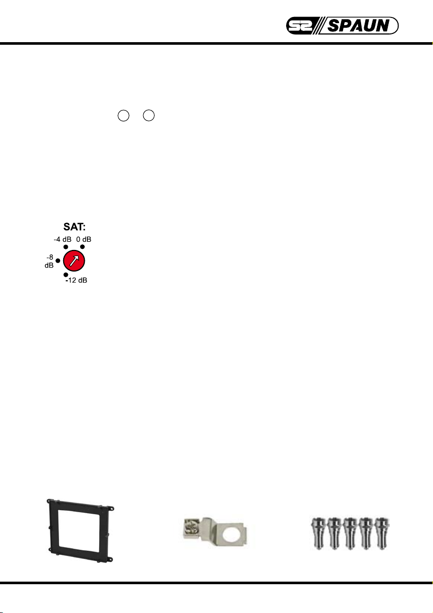
Using the changeover switch for level shifting it is possible to
lower the SAT IF signal per left or right subscriber group by a
maximum of 12 dB in increments of 4 dB.
In such a way, varying cable lengths / losses can be offset.
With a cable loss of 30 dB @ 2 GHz/100 m for example, a
4 dB increment corresponds to a cable length of 13 m.
Scope of delivery:
The SMS 55xx UI multiswitch comes with:
1. A mounting frame for wall and "sandwich" assembly for a system upgrade to
8, 12 or 16 SAT IF signals
2. Earthing clamp.
Five DC-decoupled terminating resistors ZFR 75 DC to terminate the trunkline
3.
outputs.
1. 2. 3.
3
TM
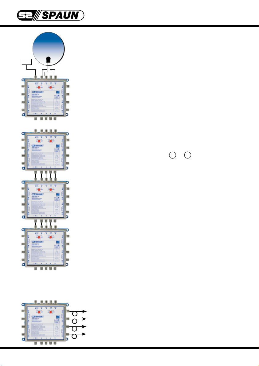
Assembly instructions:
1. Receiving a SAT system with 4 SAT IF signals
and terrestrial:
Terr.
1.1 Using the SMS 55xx UI as a standalone device
for 4 or 8 receivers; with 5 inputs (4 SAT IF signals
and 1 terrestrial input).
1.1.1 Clip the multiswitch into the mounting frame.
1.1.2 Connect the outputs of the Quattro LNB with the
SAT IF inputs in line with the multiswitch's label.
T
T
T
T
T
1.1.3 Feed terrestrial signals (if available).
(If not being used, terminate with 75 Ohm !)
1.1.4 Establish receiver outputs A ... H . Using the
integrated changeover switch for level shifting,
adjust various cable lengths / losses by -4 dB,
-8 dB or -12 dB.
1.1.5 Terminate trunk line outputs with the DC-decoupled
terminating resistors included in delivery.
1.2 Using the SMS 55xx UI in a cascade configuration
for 16, max. 24 receivers:
With central distribution it is possible to connect
the multiswitches directly with one another using
ZSV 2 S quick plug connectors. They can also be
installed as "floor distributors". Terminate the trunk line outputs of the last multiswitch with DC-decoupled
terminating resistors.
T
T
T
T
T
General recommendation:
Please note that this system may be extended to receive additional SAT systems
at a later point in time.
You should leave all receiver cables an extra
20 cm so that is possible to implement ad ditional SMR multiswitch relays later if neces sary without any problems.
4
 Loading...