

Operation Manual
for the headend BluBox 32v1
Important: Please read through these instructions thoroughly and follow them.
E - mail: info@spaun.de · www.spaun.de
Remove mains cable before opening the device!
Please follow the safety instructions enclosed!
The device is only intended for use in satellite and terrestrial receiver
systems. Any other use is prohibited. The device must be installed,
maintained, repaired and put into operation by competent people
(see EN 60065).
Byk - Gulden - Str. 22 · D -78224 Singen
Telefon: + 49 (0) 7731 - 8673 - 0 · Fax: + 49 (0) 7731 - 8673 - 17
The device must be installed indoors, in dry rooms exclusively.
Installation on or in close proximity to highly flammable materials is
prohibited. Ensure sufficient air circulation. Take care when installing
in switch cabinets or meter cabinets.
The device and the peripheral distribution devices must be earthed
in accordance with the provisions of EN 60728-11 and must remain
earthed even when the device is disassembled. For this purpose, if
available use the earthing connection of the device or the earthing terminal enclosed (4 mm
with EN 60728 - 11 and EN 60065.
The permissible ambient temperature range is: - 10 °C to + 45 °C.
Unused subscriber ports and if applicable
trunk line inputs and outputs must be terminated
Electronic devices are not household waste but rather must be disposed
of properly in accordance with directive DIN EN 50419 (reflects article
11(2) of directive 2002 / 96 / EC) of the European Parliament and the
Council of 27th January 2003 regarding used electrical and electronic
devices. At the end of the product life cycle please take this device
and dispose it via designated public collection points.
2
). Observe the safety regulations in accordance
with 75 1 resistors (ZFR 75 DC).
Technical data subject to change without notice. Errors excepted. 104040/09.17
1

1. Product description
The BluBox 32v1 headend converts DVB-S/S2 into DVB-C (QAM).
The device has 4 SAT IF and 2 AUX inputs (950 ... 2150 MHz) per 16 QAM channels. An integrated RF
switching allows connection 16 demodulators to SAT ports. Demodulated transport stream reaches
processor, which filters services, modifies SI (Service Information), generates NIT (Network Information
table), LCN (Local Channel Number), restamps PCR (Program Clock Reference). Then transport stream is
forwarded to QAM modulators, which produces independent DVB-C RF signals.
Configuration and monitoring take place via web interface.
The headends are equipped with redundant switched-mode power supply.
The housing is intended for wall mounting or the mounting in a 19“ rack.
The product is intended for indoor usage only.
2. Safety instructions
Installation of the BluBox 32v1 must be done according IEC 60728-11 and national safety standards.
The BluBox 32 v1 is powered from mains 240 V~. This voltage is dangerous to life.
Any repairs must be done by a qualified personnel only.
The device correspond to Protection Class I.
To avoid the electric shock follow these instructions:
s Do not plug BluBox 32v1 into the mains supply if the power cord or plug is damaged.
s To disconnect the BluBox 32v1 from the mains completely, disconnect plug from mains socket.
s The mains socket must be easily accessible.
s The BluBox 32v1 shall not be exposed to dripping or splashing water and no objects filled with
liquids, such as vases, shall be placed on it.
s Avoid placing device next to the central heating components and in areas of high humidity.
s No naked flame sources, such as lighted candles, are allowed to be placed on BluBox 32v1.
s If the device has been kept in cold conditions for a long time, keep it in a warm room no less
than 2 hours before plugging into the mains.
s Do not insert any objects into ventilation openings.
s The ventilation should not be impeded by covering the BluBox 32v1 with items, such as
newspapers, table-cloths, curtains.
s Mount the BluBox 32v1 on not flammable vertical wall or in not flammable installation box in
vertical position.
Mounting position:
- only vertical position (as shown in the picture)
- no overhead installation
- only with enclosed mounting brackets
2

3. Technical data
Model
Art. No.
BluBox 32v1
821659
EAN 4040326216590
Input frequency range 950 ... 2150 MHz
Input level / impedance 45-85 dBμV / 75 Ohm
LNB power and control
Vertical, Low 0 V / 13 V
500 mA max. total
Horizontal, Low 0 V / 18 V
Vertical, High
0 V / 13 V 22 kHz
or DiSEqC
Horizontal, High
0 V / 18 V 22 kHz
or DiSEqC
Aux 1 0 V / 13 V
250 mA max. total
Aux 2 0 V / 18 V
Modulation DVB-S (QPSK) DVB-S2 (QPSK/8PSK)
Symbol rate 2 - 45 MS/s 2 - 45 MS/S (QPSK, 2 - 31,5 MS/s (8PSK)
Code rate 1/2, 2/3, 3/4, 5/6, 7/8
QPSK 1/2, 3/5, 2/3, 3/4, 4/5, 5/6, 8/9, 9/10
8PSK 3/5, 2/3, 3/4, 5/6, 8/9, 9/10
Input roll off 35 % 20 %, 25 %, 35 %
Signal processing ETS 300 421 ETS 302 307
Output frequency range 48 - 858 MHz, by step 100 kHz
RF channel allocation independent from other channels
Output level per carrier / impedance typ. 87 dBμV / 75 Ohm
Total output level adjustment 0 ... -15 dB by 0.5 dB step
MER > 40 dB
Modulation DVB-C QAM16, QAM32, QAM64, QAM128, QAM256
Output channel bandwidth/
symbol rate
4 ... 8,3 MHz / 3,5 ... 7,2 MS/s
Output roll off 15 %
Output signal processing EN 300 429, ITU T J.83 A (Annex A)
Loop through frequency range 45 - 862 MHz
Loop through loss typ. 3 dB
Input data rate max. 90 Mbps per transponder
Supply voltage 200 - 240 V / 50 Hz
Power consumption max. 115 W
Operating temperature - 10° ... + 45 ° Celsius
Dimensions in mm 486 x 356 x 150
Default IP address 192.168.1.250
Default Login data username: admin password: admin
3
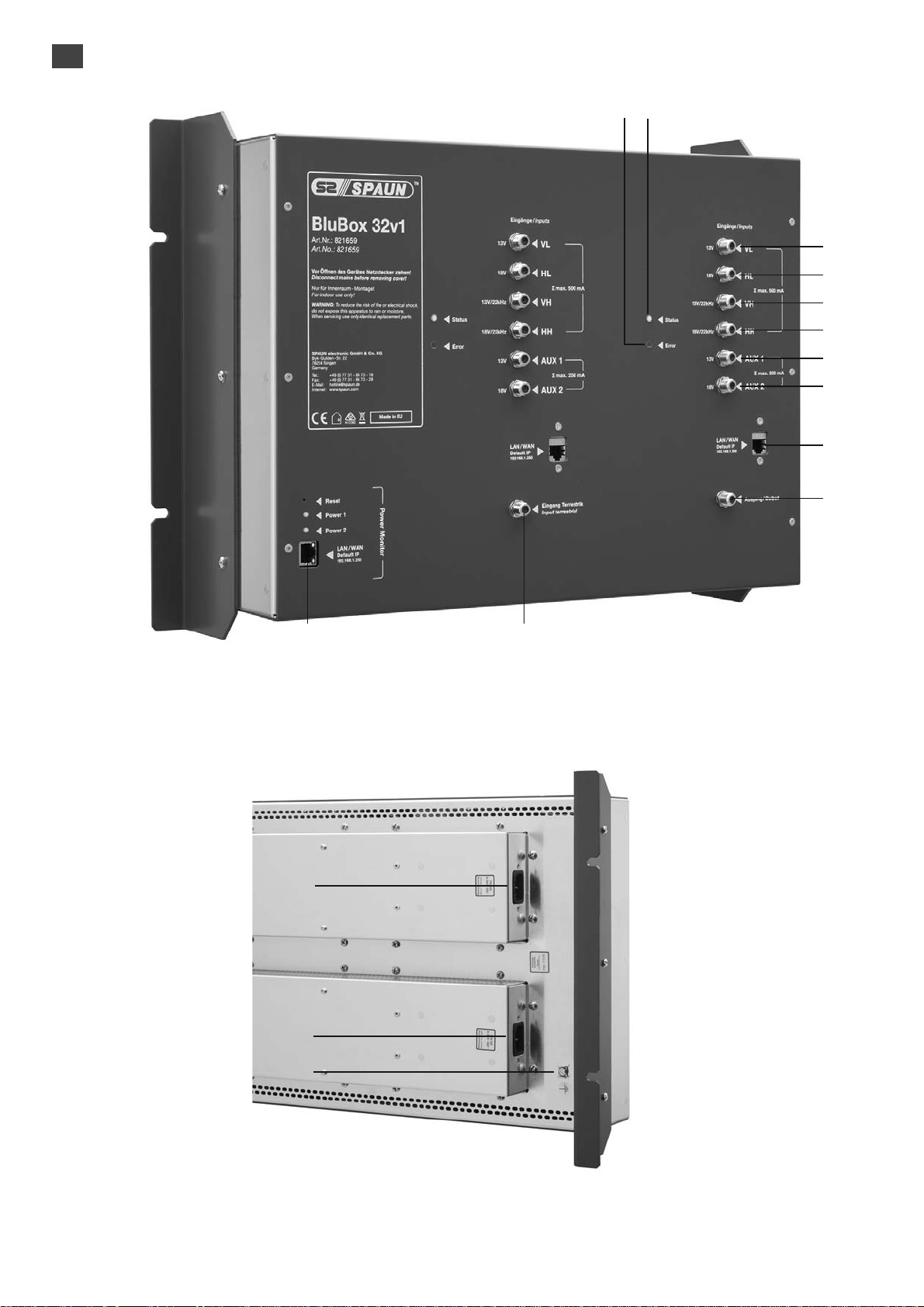
4. External view
910
1
2
3
4
5
6
7
8
1112
Picture 1. External view of the BluBox 32v1 (front side); different housing color possible
13
14
15
Picture 2. External view of the BluBox 32v1 (rear side); different housing color possible
4

Front side:
1. VL - vertical Lo band SAT input. +13 V output to LNB.
2. HL - horizontal Lo band SAT input. +18 V output to LNB.
3. VH - vertical Hi band. +13 V/22 kHz output to LNB.
4. HH - horizontal Hi band. +18 V/22 kHz output to LNB.
5. AUX 1 - this port will not be used for disturbing FOXTEL signal. It’s for testing purpose.
auxiliary 1 SAT input. +13 V output to LNB.
This port can be accessible from 9th -16th demodulators only.
6. AUX 2 - this port will not be used for disturbing FOXTEL signal. It’s for testing purpose.
auxiliary 2 SAT input. +18 V output to LNB.
This port can be accessible from 9th -16th demodulators only.
7. 10/100 Mb ETH - Ethernet control port
8. RF OUT - RF output
9. STATUS - LED is green when device has booted succesfully.
10. ERROR - error indicator. Red light indicates, that at least one error exists at the moment.
11. RF IN - RF loop through input. An output of another transmodulator can be connected here.
12. Power Monitor - Control section for the internal power supplies with GUI and xml file export.
Username: spaun
Password: letmein
Rear side:
13. Mains socket - power supply 1
14. Mains socket - power supply 2
15. Functional grounding clamp
5
5. Installation instructions
Read the safety instruction first.
Installation of system according standard IEC 60728-11 ensures safety of personnel and prevents apparatus
against damaging due to lightning or other sources of overvoltage surges.
Mount the BluBox 32v1 on not flammable wall or in not flammable installation box in vertical position.
If any RF connector on the BluBox 32v1 is not used, connect the 75 1 load supplied.
Connect power plug of BluBox 32v1 to the mains when functional grounding and RF cables are connected
correctly.
Shielded cable is recommended for Ethernet connection.
It is recommended to connect power plugs of BluBox 32v1 to different lines of the mains or one to the line
directly, another through uninterruptible power source (UPS).
The power monitor indicates error when one of PS is disconnected/out of order. Disconnected PS does
not disturb working of other PS.
6. Operation
Power on the device. When powering on is finished, device will run according to the latest used configuration
and the Status LED illuminate green. Device monitores PMT (Program Map Table) of every active service
constantly and updates transport stream parameters to the output if any changes detected, for ex: new
PIDs (Packet Identifier) detected or removed. So the end-equipment should detect any changes of
transport stream automatically as well. The exception is very rare situation, when the same PMT PID is
shared between several services. In this case, PMT monitoring is disabled for these services.
7. Control panel
The BluBox 32v1 can be configured using any web browser. The exception is Internet Explorer, which
must be 10.0 version or higher. Default IP address of device is 192.168.1.250, so it can be accessed at url
http://192.168.1.250/. Login window will appear on the website (Picture 3.)
Default username and password are admin/admin. Press “Login” button
to open control panel. Main page of device control panel will appear.
Each tab on page top controls separate section of parameters. “System
menu” can be opened by moving a mouse over the menu. To open any
other control window, click on the tab on this control window.
Picture 3. Login window
7.1. Main
“Device information” table shows main device information – serial number, device model, software version, etc.
Parameter “Title” can be changed by pressing “Change” button. This title will be displayed as a browser
title and will be seen on the right top side of the browser.
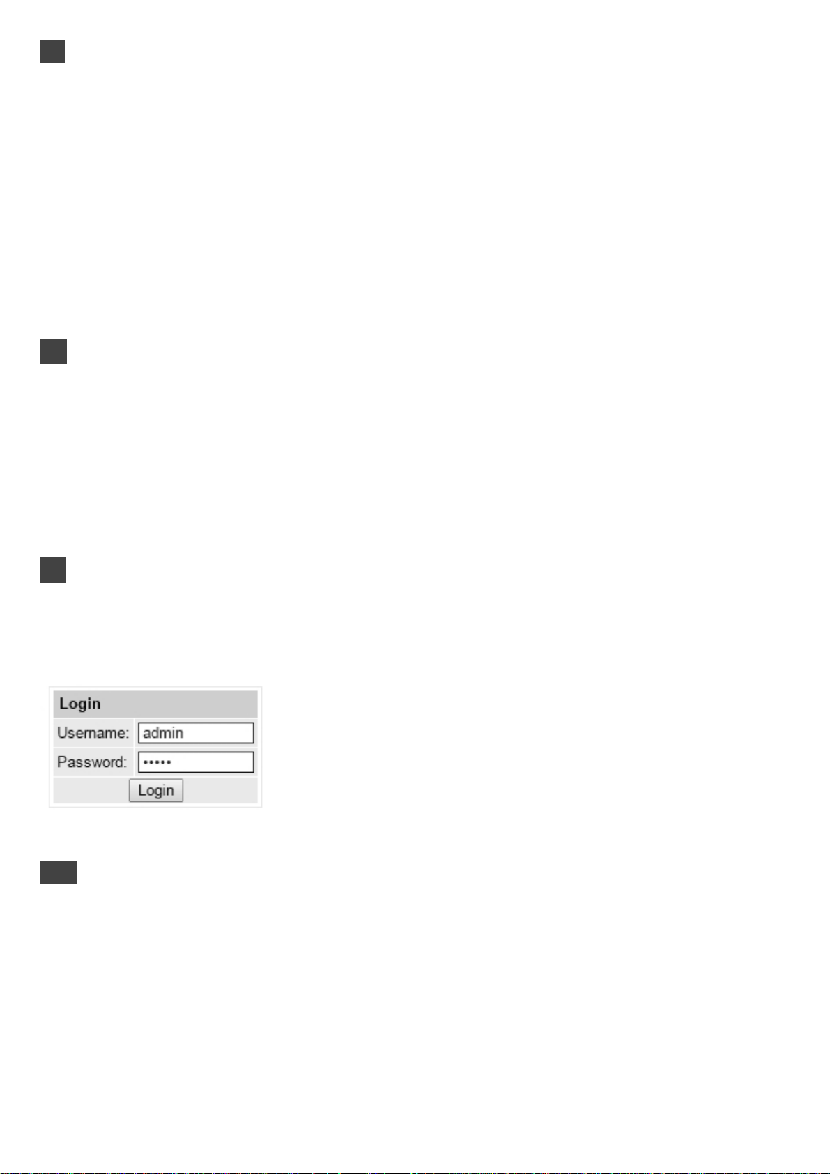
“Output bitrates” table shows the output bitrate status of each channel in real time (Picture 4.). Horizontal
bar shows percentage of used available bandwidth of the channel. The 1
actual bitrate in Mbps. Next number shows maximum allowed bitrate in the channel and it depends on
modulation parameters. Ensure, that maximum actual bitrate would not reach more than 95% of available
bandwidth. Otherwise bitrate overflow may occur.
“Diagnostic information” table shows actual errors.
“Temperature measurement” table shows temperature of several points of the device - demodulator,
modulator and internal temperature. Ensure, that none of these temperatures would reach 90°C degree.
Otherwise output quality parameters may get worse. Reaching 110°C may damage the device.
st
number right to the bar shows
6
7.2. LNB settings
Picture 4. Output bitrates
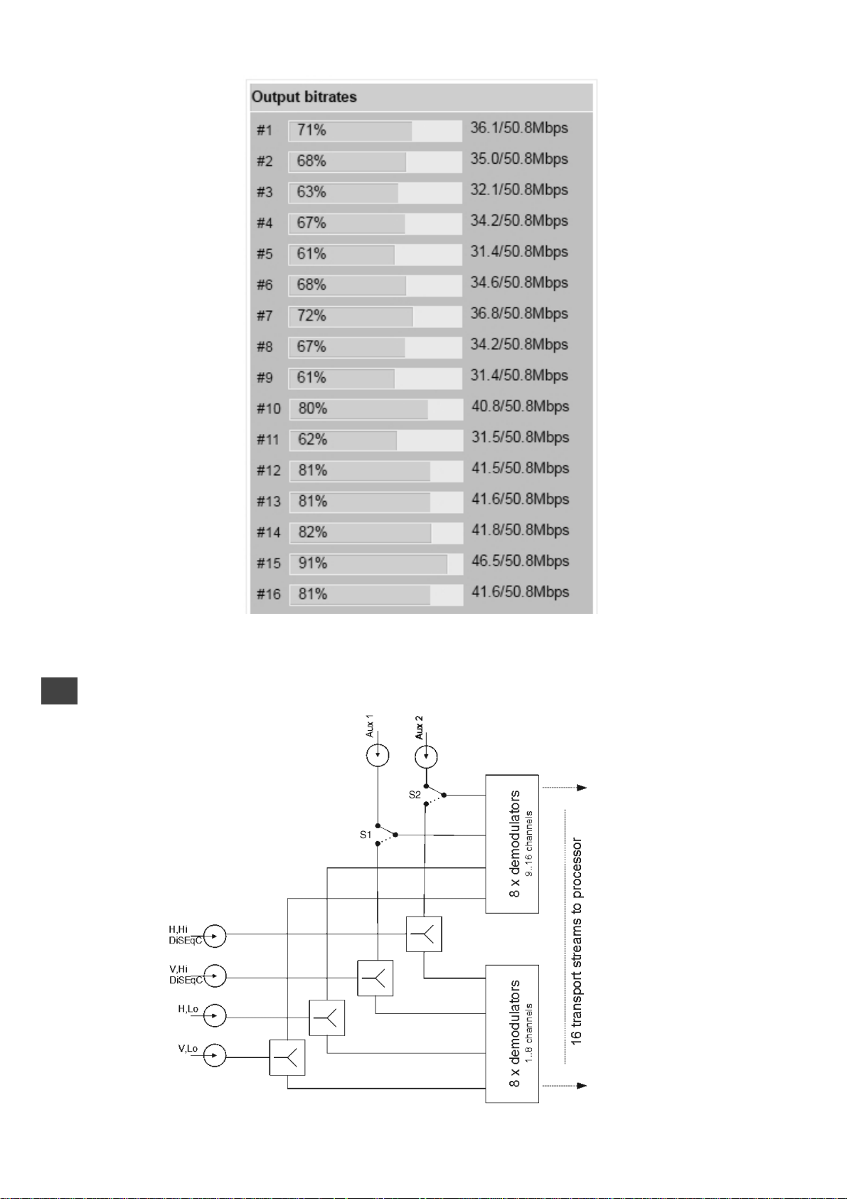
Picture 5. Structure of SAT inputs
7

Picture 5 shows internal structure of satellite inputs. Each SAT port has individual settings, where a power
supply can be switched on/off, LNB Lo/Hi frequency or DiSEqC parameters set up:
VL: 0 V or +13 V;
HL: 0 V or +18 V, see picture 6.
VH: 0 V or +13 V 22 kHz. This port supports DiSEqC as well, see picture 7.
HH: 0 V or +18 V 22 kHz. This port supports DiSEqC as well;
Aux 1: this port will not be used for disturbing FOXTEL signal. It’s for testing purpose only.
0 V or +13 V. When Aux 1 LNB power is set to “RF V,Hi”, this port is disabled, see pictures 5, 8.
Aux 2: this port will not be used for disturbing FOXTEL signal. It’s for testing purpose only.
0 V or +18 V. When Aux 2 LNB power is set to “RF H,Hi”, this port is disabled.
Picture 6: LNB power setup window
Picture 7: LNB DiSEqC parameters setup window
Picture 8: LNB power setup of AUX inputs
RF signal from Aux 1 and Aux 2 ports can be connected to 9-16th demodulators only or be disabled. When
Aux 1 LNB power is set to 0V or +13V, switch S1 connects Aux 1 port to 9-16th demodulators and
connects DC 0V or +13V for LNB. When Aux 1 LNB power is set to “RF V,Hi”, switch S1 connects 9-16th
demodulators from port Aux 1 to port V,Hi, disconnecting DC from this port, see picture 5.
Summary output current for LNB from ports VL, VH, HL, HH is shown in Specifications independing from
Aux 1, Aux 2 settings.
Summary output current for LNB from ports Aux 1, Aux 2 is shown in Specifications independing from
another ports settings.
7.3 RF inputs
16 demodulators can be set up in this section. See picture 9. “SAT input” parameter can switch demodulator
off or connect to any available RF input. Demodulators 1-8th can connect only to VL/HL/VH/HH inputs.
Depending on “Aux In/LNB Power” parameter of “LNB Settings” section, in case of “SAT input” 3
rd
and 4th
selection, demodulators 9-16th will be connected either to VH/ HH or to Aux 1/2 ports.
“Input frequency” parameter is a frequency of transponder in MHz. Ensure, that SAT IF frequency
(FRtransponder - LNB Lo/Hi) fits into demodulator’s input frequency range.
In case of DiSEqC, device will try (if possible) to automatically select Lo or Hi frequency to fit into the IF
frequency range.
“Symbol rate” parameter is a symbol rate of transponder in kSym/s.
“Modulation standard” allows to select modulation type of DVB-S or DVB-S2.
Press “Update” button to set new parameters.
8
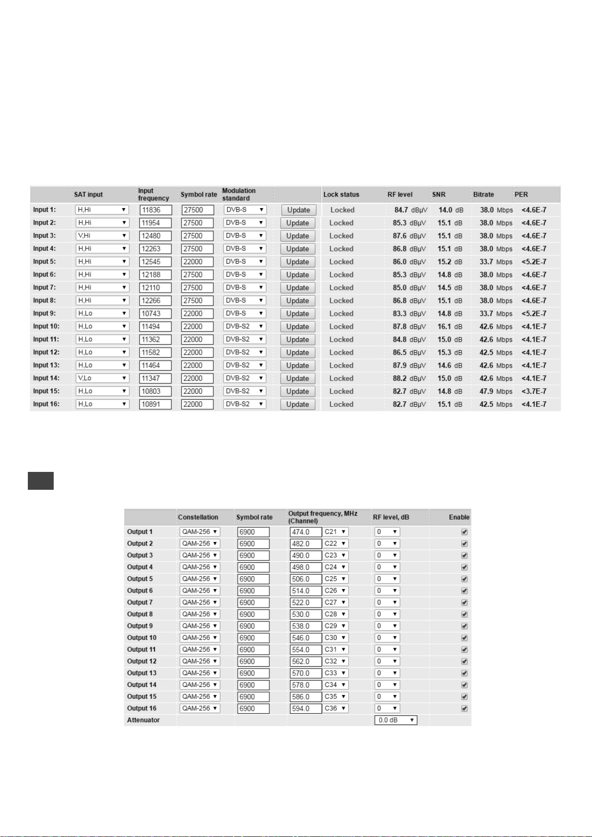
There are various status parameters of input signal right to the &Update” button. “Lock status” can have
following values:
- “Inactive”, when the input channel (demodulator) is turned off;
- “Locked”, when demodulator is locked to the transponder;
- “Unlocked”, when demodulator is unlocked. This state generates error in diagnostic window as well. If the
channel is not used, it’s recommended to turn it off instead of leaving unlocked. It will save power consumption.
“RF level” and “SNR” (Signal Noise Ratio) are measured parameters of input signal. “Bitrate” is the transport
stream’s bitrate of the transponder. PER (Packet Error Ratio) shows the ratio of invalid received packets
and total received packet. A sign “<” before the value means, that there was no any errors within that
number of packets. To reset PER counters, simply click onto the PER value.
7.4 RF outputs
Picture 9: RF inputs
Picture 10: RF outputs
9

16 independent QAM modulators can be setup in this section. There is no requirement for channels to be
adjacent or sorted by frequency, see picture 10. Each channel can have own constallation
QAM-16/32/64/128/256, symbol rate 3500..7200 Mbps. Note, that symbol rates higher than 6956 kSym/s
will exceed 8 MHz bandwidth, so these symbol rates should be used carefully.
“Output frequency” parameter can be entered manually or selected as a channel from combobox. Only
C21(474 MHz)...C69 (858 MHz) can be selected from the list. If you need any other frequency – just add it
manually. Frequency step is 0.1 MHz.
RF level for each channel can be adjusted in a range of -3...+3 dB. “Enable” checkbox will enable channel
to the output. Global attenuator can be entered up to 15 dB.
Press “Update” to change settings. In case, if any modulation parameter was changed, whole 16 modulators
will be restarted with new settings. Exceptions are “RF level” and “Attenuator”. Changes in these parameters
will not restart the modulator.
7.5 TS outputs
Several tables related to NIT generation exist in this section. “Global TS parameters” (picture 11) describes
following TS parameters:
Picture 11: Global TS parameters
- Network ID is unique within the geographical region defined by the “country_code”. For a cable network,
usually this is a single country code plus 0x2000 (8192). If there are more modulators in the network, they
must have the same Network ID.
Proper value depending on your country and operator can be found here:
http://www.dvbservices.com/identifiers/network_id?page=1
- Private data specifier (in hex format) can be inserted in the NIT table for proper LCN description. This
value is described in TS 101162 specification. NorDig standard requires 00 00 00 29 value, UK should use
00 00 23 3A value. Other options can be found here:
http://www.dvbservices.com/identifiers/private_data_spec_id?page=1
The parameter will not be inserted into NIT if value is set to zero.
- “Network name” is the name of the network.
- “Timezone” parameter is used for proper time records in logs. It has no effect to broadcast.
- “Date and time source” is a channel for a source of time. It is used for proper time records in logs and
has no effect to broadcast. All original TDT/TOT (Time Data Table/ Time Offset Table) PID 20 pass directly
from demodulators to each output without modification.
The 2
nd
table in the page describes Transport stream ID and Original network ID of each channel
(see picture 12). Each stream in a network must have unique ID, called “Transport stream ID”. An
Original_Network_ID is defined as the “unique identifier of a network”. It can be linked to NetworkID or
used value from this location:
http://www.dvbservices.com/identifiers/original_network_id?page=1
10

Picture 12: Transport stream and original network IDs
In case of transparent mode, Original network ID and Transport stream ID fields will be disabled. These
values will be the same as in input transport stream, and will be updated automatically if any changes
detected.
Very important part in this page is the 3
rd
table (picture 13), where other streams in the network can be
described.
Picture 13: Description of other streams in the network
Every channel in the network must be described in NIT. Otherwise TV automatic channel tuning function
will not find all channels. So, if there are more modulators in the network, all channels must be included in
this table. If there are more devices manufactured by Spaun, which are controlled via Ethernet, all broadcast
information can be captured automatically by adding it’s IP address and pressing “Load” button. In case
if the same frequency was added already, that record will be updated. Otherwise, a new record will be
inserted.
All listed frequencies will be monitored in the network via standard SSDP protocol. NIT tables will be
regenerated if any change in any listed frequencies detected.
7.6 IP parameters
All device IP settings can be setup here – IP address, subnet mask, gateway, DNS (Domain Name System),
see picture 14. DNS server is used for e-mail sending only.
IP parameters will be updated immediately after pressing “update” button and redirect to new location.
11

Picture 14: IP parameters Picture 15: E-mail-settings
The device can send e-mail reports if errors were detected. SMTP protocol is used for that. Picture 15
shows parameters related to this feature. “Enable e-mail error report” checkbox enables error
monitoring. All errors within “timeout” period will be gathered, and send to the e-mail address, provided
in “Receiver e-mail address” input box. Comma separated e-mail addresses can be used to send report
to multiple addresses. The timer will be started as soon, as the first error is detected, and stopped when
e-mail is sent. The timer will be restarted again if a new error will appear.
“Sender e-mail address” can be used as authentication in the SMTP server side.
SSL (SMTPS) protocol is not supported.
7.7 Services
One channel at a time can be setup in this page. Select proper channel from the list at “Choose input
channel” combobox (see picture 16).
Picture 16: Services
A list of scanned services of selected channel will appear. “Rescan” button will load all service information
of that channel. “List of services” table shows a list of available services. Icon before the service name
indicates service type. Bitrate of each service is measured in real time. “LCN” field is a Logical Channel
Number. Every service can have a “channel number” and TV will sort channels according to it. Just ensure,
that all services in all channels have different numbers. Value 0 means, that LCN for that service is not used
at all and TV will sort these channels according to it’s own rules. If channel numbers are added, but TV
does not recognize it, check the following:
- If TV supports LCN?
- If Network ID and Original Network ID values are valid for the country, which is selected on TV?
“Enable” checkbox enables the service to the output.
Press onto “+” sign and service information will be extended (see picture 17).
12

Picture 17: Service details
Service title and provider can be edited (multilanguage character support). “Scrambled flag” will be inserted
into SDT (Service Description Table). Unchecking this checkbox will not descramble the content. It only
carries information about the scrambling status of the service.
Individual streams can be disabled as well.
Note: transparent mode will ignore all these settings.
Press onto “Update” button to save changes and execute.
In case of transparent mode, all services of transponder will be passed to the output, including original
PAT, SDT, PMT, EIT, CAT tables. The exception is NIT table, which is generated by device, and will be
updated if any changes detected in the input stream. Note, that "Original network ID" and "Transport
stream ID" values will be used original.
Use the following steps to turn on transparent mode: press "Rescan" button to scan services for the first
time; mark "transparent mode" checkbox, like in picture 16; press "Update".
7.8 System menu
This menu tab contains following submenu items: “Event logs”, “Export parameters”, “Import parameters”,
“Firmware upgrade”, “User management”, “ Restore defaults ”, “ Reset the device ”, “Language”. Mouse
over to show the list of this submenu.
7.8.1 Event logs
Various important events, errors, warnings will be logged into the system (see picture 18).
Picture 18: Event logs
Each record has an event type, which can be used to filter particular messages. Just select checkboxes in
the “Logs filtering” table and press “apply”. Other messages will be hidden.
“Erase logs” button will erase all logs from the system.
Each record has a log time when the event appeared. Device has internal clock and it’s value is updated
from the transport stream. Timezone takes effect there, which can be setup at “TS output/Timezone”.
7.8.2 Export parameters
All settings of transmodulator can be exported for backup or copying to another device. Press “Export
parameters” and “parameters.xml” file will be downloaded to PC. This file can be imported only to the
same type of device.
7.8.3 Import parameters
Exported parameters can be imported back to the device. Press onto “Click to select file” button
(see picture 19) to select exported file.
13

Picture 19: Import parameters
Press “Upload” button to send the file to the device. Several seconds will take to update all parameters
after file upload. After that, device will start to work with new configuration. No restart requires.
7.8.4
7.8.5 User management
User may change a password here. Length of password up to 16 symbols. Type current password and
double enter new password to change it.
If logged in user has admin role, new users can be added on another table (see picture 21).
Picture 21: User management
Enter it’s username, password, select a role and press “Add” button.
Only administrator (user with a role “admin”) may manage other users.
7.8.6 Restore defaults
All parameters will be restored back to factory defaults after confirmation. The exception – IP address and
users – these parameters will be unchanged. To restore IP address and system password to system
defaults, see “7.8.7”.
Several seconds can take to restore all parameters, so be patient.
7.8.7 Reset the device
Device will be restarted after confirmation to do it. Including the IP address.
7.8.8 Language
Device control panel supports several preinstalled languages. A change of language requires system
restart. Note, that all previously logged records will remain in previous language.
14
8.
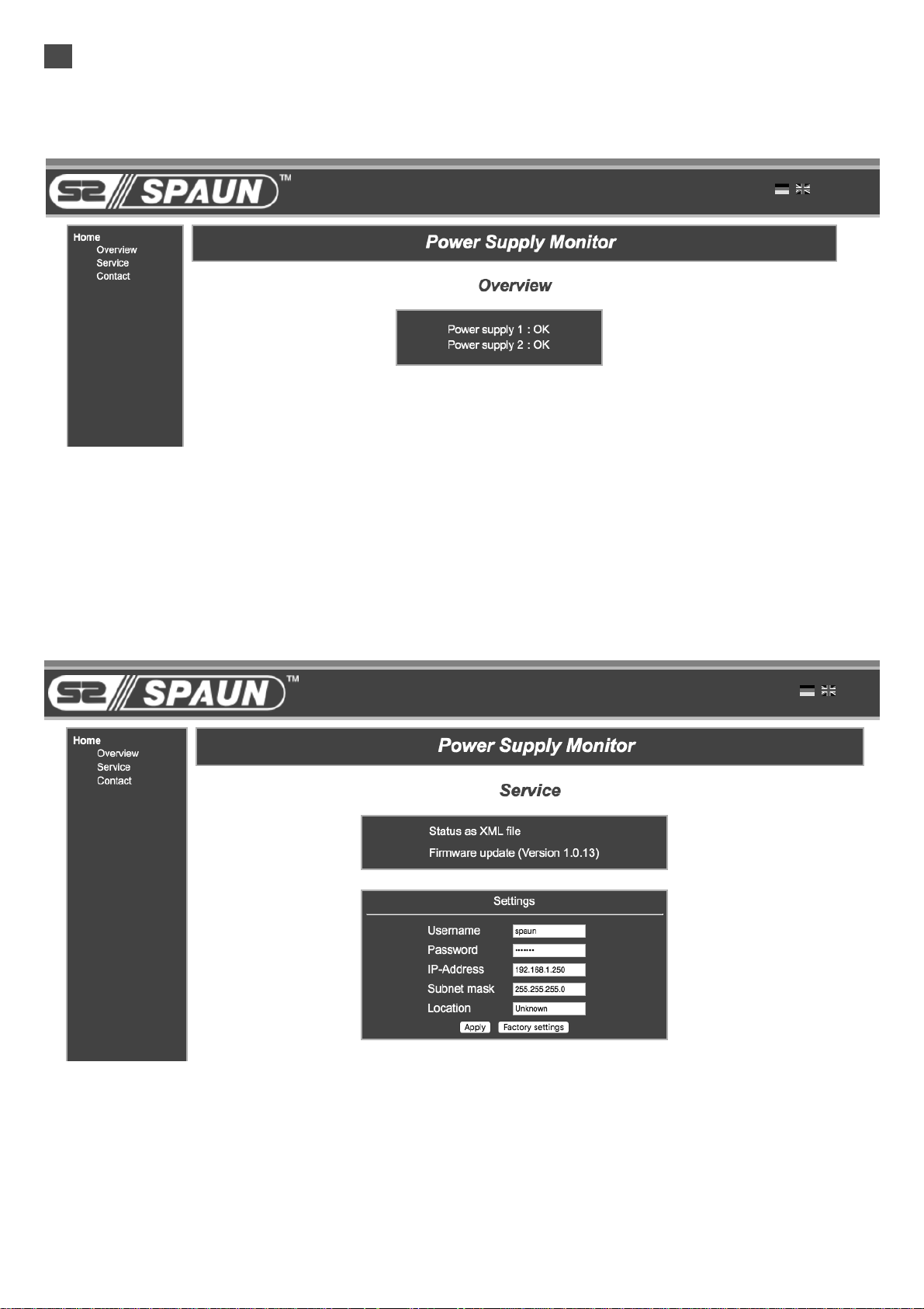
7.8.3 Power Monitor
The Power Monitor allows monitoring of the status of the two power supplies.
If you enter the address 192.168.1.250 in the web browser, the overview page is displayed.
(Picture 22).
Picture 22: Overview
If one power supply fails, it is shown in the dialog.
To access the service menu, enter the user name and password:
Username: spaun
Password: letmein
Picture 23: Service menu
The service menu allows you to change the IP address. Furthermore, the status of the two power supplies can be retrieved via an XML file.
15

Distributed by Jonsa Australia Pty Ltd
Head Office
Jonsa Australia Pty Ltd
Unit D2, 3-29 Bimie Ave
Lidcombe NSW 2141
Australia
Ph: 1300 660 155
Fax: 1300 250 407
WA Office
Jonsa Australia Pty Ltd
Unit 1 / 7 Mallaig Way
Canning Vale NSW 6155
Australia
Ph: 08 9256 3470
Fax: 08 6254 2280
Correspondence
Jonsa Australia Pty Ltd
PO Box 6147
Silverwater
NSW 1811
Email: sales@jonsa.com.au
Web: www.jonsa.com.au
16
 Loading...