

Page 1
1
05/05 ID# M866041
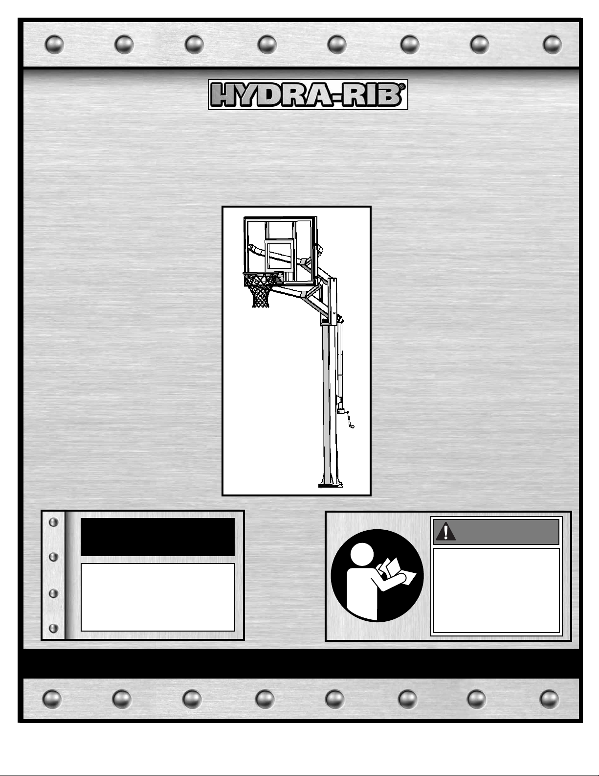
In-Ground Basketball System
Owners Manual
Customer Service Center
• N53 W24700 South Corporate Circle • Sussex, WI 53089 • U.S.A.
Toll-Free Customer Service Number for U.S: 1-800-334-9111
Internet Address: http://www.hydra-rib.com
Write Model Number
From Box Here:
WARNING!
READ AND UNDERSTAND
OPERATOR'S MANUAL
BEFORE USING THIS UNIT.
FAILURE TO FOLLOW
OPERATING INSTRUCTIONS
COULD RESULT IN INJURY
OR DAMAGE TO PROPERTY.
Page 2
2
ID# M866041 05/05
IMPORTANT! WRITE MODEL NUMBER FROM BOX ONTO PAGE 1 OF THIS OWNERS MANUAL
WARNING
FAILURE T O FOLLOW THESE WARNINGS MAY RESULT
IN SERIOUS INJURY AND/OR PROPERTY DAMAGE.
Owner must ensure that all players know and follow
these rules for safe operation of the system.
• See instruction manual for proper installation.
• DO NOT HANG on the rim or any part of the system
including backboard, support braces or net.
• During play, especially when performing dunk type
activities, keep player's face away from the backboard, rim
and net. Serious injury could occur if teeth/face come in
contact with backboard, rim or net.
• Do not slide, climb, shake or play on pole.
• When adjusting height, keep hands and fingers away from
moving parts.
• Do not allow children to move or adjust system.
• During play, do not wear je
welry (rings, watches,
necklaces, etc.); objects may entangle in net.
• Keep organic material away from pole base . Grass, litter,
etc. could cause corrosion and or deterioration.
• Chec
k pole system for signs of corrosion (rust, pitting,
chipping) and repaint with with exterior enamel paint. If
rust has penetrated through the steel anywhere, replace
the pole immediately.
• Check system before each use for proper ballast, loose
hardware, excessive wear and signs corrosion and repair
before using.
• Check system before eac
h use for instability.
• Never play on damaged equipment.
• Keep pole top covered with cap at all times.
201255 2/99
1-800-558-5234
SAFETY INSTRUCTIONS
Most injuries are caused by misuse and/or not following instructions.
Use caution when using this system.
• If using a ladder during assembly, use extreme caution.
• Two (2) people are recommended for this operation.
• Seat the pole sections properly. Failure to do so could allow the pole sections to
separate during play.
• Before digging, contact utility company to locate underground power cables, gas,
and water lines. Ensure there are no overhead power lines within 20 ft. (7 m) radius
of pole location.
• Climate, corrosion, excessive use, or misuse could result in system failure.
• If technical assistance is required, contact Huffy Sports.
• Minimum operational height is 6'6" (1.98 m) to the bottom of backboard.
• This equipment is intended for home recreational use only and NOT excessive
competitive play.
• Read and understand the warning label affixed to pole. Label is shown on page 2.
• The life of your basketball pole depends on many conditions. The climate,
placement of the pole, the location of the pole, exposure to corrosives such as
pesticides, herbicides or salts are all important.
• Adult supervision is recommended when adjusting height.
• Serious injury could occur if teeth/face come in contact with backboard, net, or rim.
FAILURE TO FOLLOW THESE SAFETY INSTRUCTIONS MAY RESULT IN
SERIOUS INJURY, PROPERTY DAMAGE AND WILL VOID WARRANTY.
Owner must ensure that all players know and
follow these rules for safe operation of the system.
To ensure safety, do not attempt to assemble this system without following the
instructions carefully. Proper and complete assembly, use and supervision is
essential for proper operation and to reduce the risk of accident or injury. A
high probability of serious injury exists if this system is not installed,
maintained, and operated properly. Check entire box and inside all packing
material for parts and/or additional instructional material. Before beginning
assembly, read the instructions and identify parts using the hardware identifier
and parts list in this document.
For more information on assembly, placement, proper use and maintenance,
visit The American Basketball Council website at http://www.smarthoops.com.
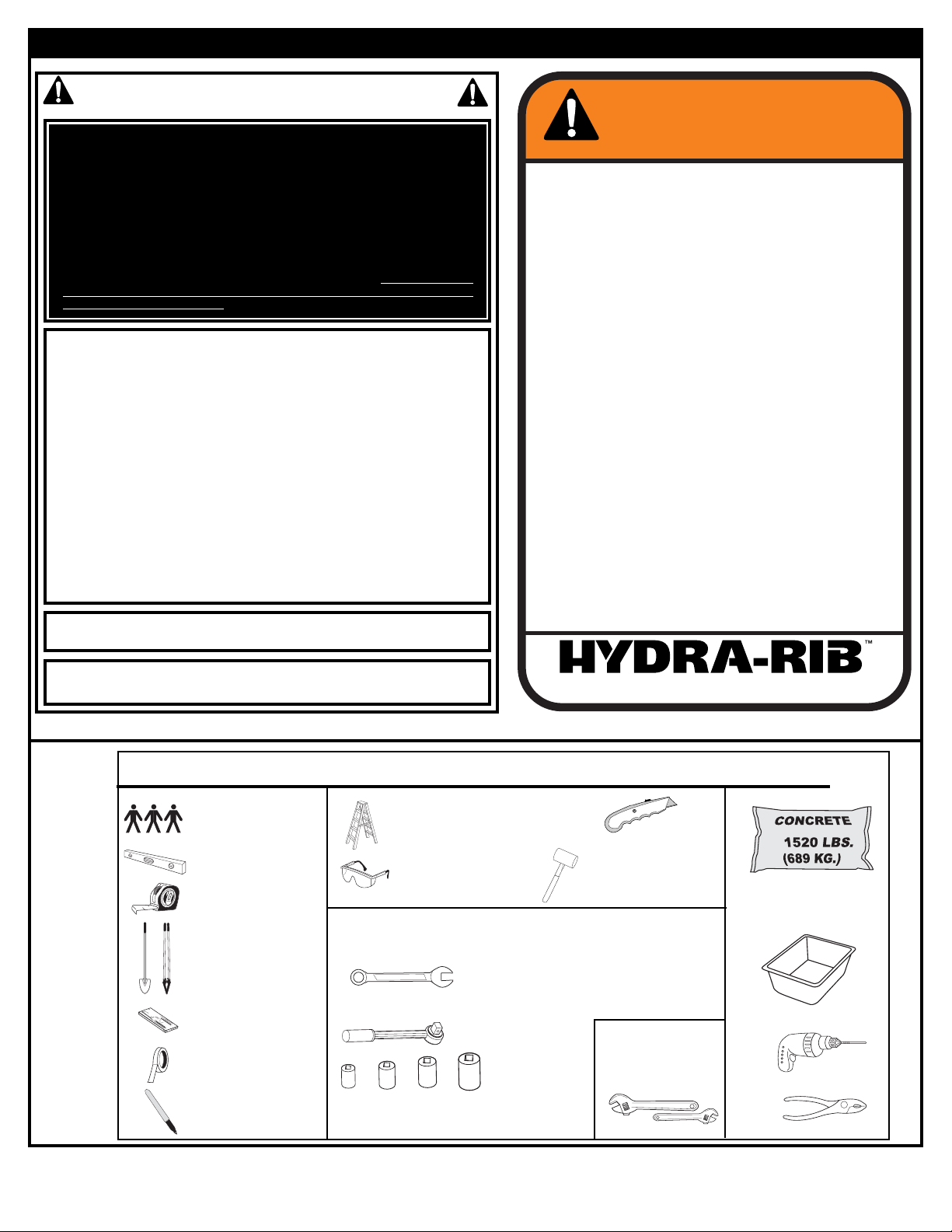
REQUIRED TOOLS AND MATERIALS:
• 3 People
• Carpenter’s Level
• 15’ Tape Measure
• Shovel & Post Hole
Digger
• Wood Board (scrap)
• Masking Tape
• Marker
• (2) Stepladders 8 ft. (2.4 m)
• Safety Goggles
•
• Container to Mix
• Drill
• Pliers
• (2 each) Wrenches and/or Socket Wrenches and
Sockets (Deep-Well Sockets are Recommended).
1/2"3/8"
9/16"
3/4"
• Optional: Large &
Small Adjustable
Wrenches
1/2"3/8" 9/16" 3/4"
• (1) Utility Knife
• (1) Rubber Mallet
Page 3
3
05/05 ID# M866041
Item Qty.
Part No. Description
1 1 968860 Pole
2 1 998850 Plate, Anchor, Black
3 1 Rim Assembly
4 1 Net
5 4 203017 Nut, Hex, 3/8-16
6 4 203300 Washer, Locking, 3/8
7 2 250001 Bolt, Hex, Tap, 3/8-16 x 4” Long
8 4 250002 Bolt, Hex, Tap, 3/8-16 x 2” Long
9 1 203457 Label, Logo, Vinyl, 2.3” x 2.7”
10 1 Backboard
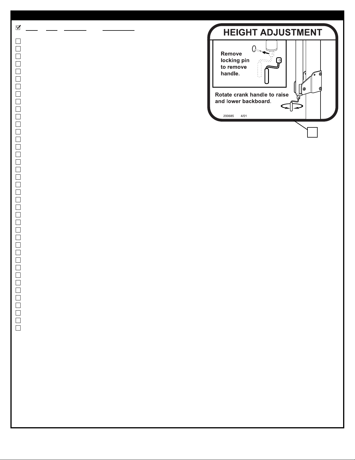
11 1 200685 Label, Height Adjustment
12 1 204940 Screw Jack
13 2 220563 Screw, 1/4-20 x 1/2” Long, Rim Cover
14 1 808545 Rod, Spacer, 19.8”, Zinc
15 1 203641 Bolt, Hex, 1/2-13 x 9.5” Long, Black Oxide
16 1 Cover, Rim
17 1 978850 Yoke, Upper, Center, Pole
18 1 988855 Yoke, Lower, Center, Pole
19 4 200573 Bolt, J, 5/8-11 x 24, 3” Thread
20 1 203630 Bolt, Hex, 1/2-13 x 5, Black Oxide
21 16 203635 Washer, Flat, .053 I.D., .08 O.D., Black Oxide
22 10 203637 Nut, Lock, Nylon Insert, 1/2-13, Black Oxide
23 1 203641 Bolt, Hex Head, 1/2”-13 x 6”
24 9 204046 Washer, Flat, 5/8, Black Oxide
25 13 204057 Nut, Hex, 5/8-11, Black Oxide
26 1 204669 Spacer, .50 I.D. x .75 x 4” Long, Steel
27 24 204670 Bushing, Plastic
28 3 204728 Bolt, Hex, 1/2-13 x 9.25, Black Oxide
29 4 204733 Screw, #8, .50 Long
30 2 204735 Height Indicator, Plastic
31 4 204739 Label, Height Indicator, Right
32 4 204740 Label, Height Indicator, Left
33 4 206311 Spacer, .52 I.D. x .75 I.D. x .5” Long, Plastic
34 4 206271 Bolt, Hex, 1/2-13 x 2.5, Zinc
35 1 204921 Washer, Barrel
36 1 204922 Pin, Hitch
37 1 204923 Pin, Cotter, #8
38 2 202666 Name Plate
39 3* 216279 Bolt, Hex, 1/2-13 x 6.5, Black Oxide
* You May Have Extra Parts With This Model.
PARTS LIST
11
Page 4
4
ID# M866041 05/05
Item #5 (4)
Item #35 (1)
Item #13 (2)
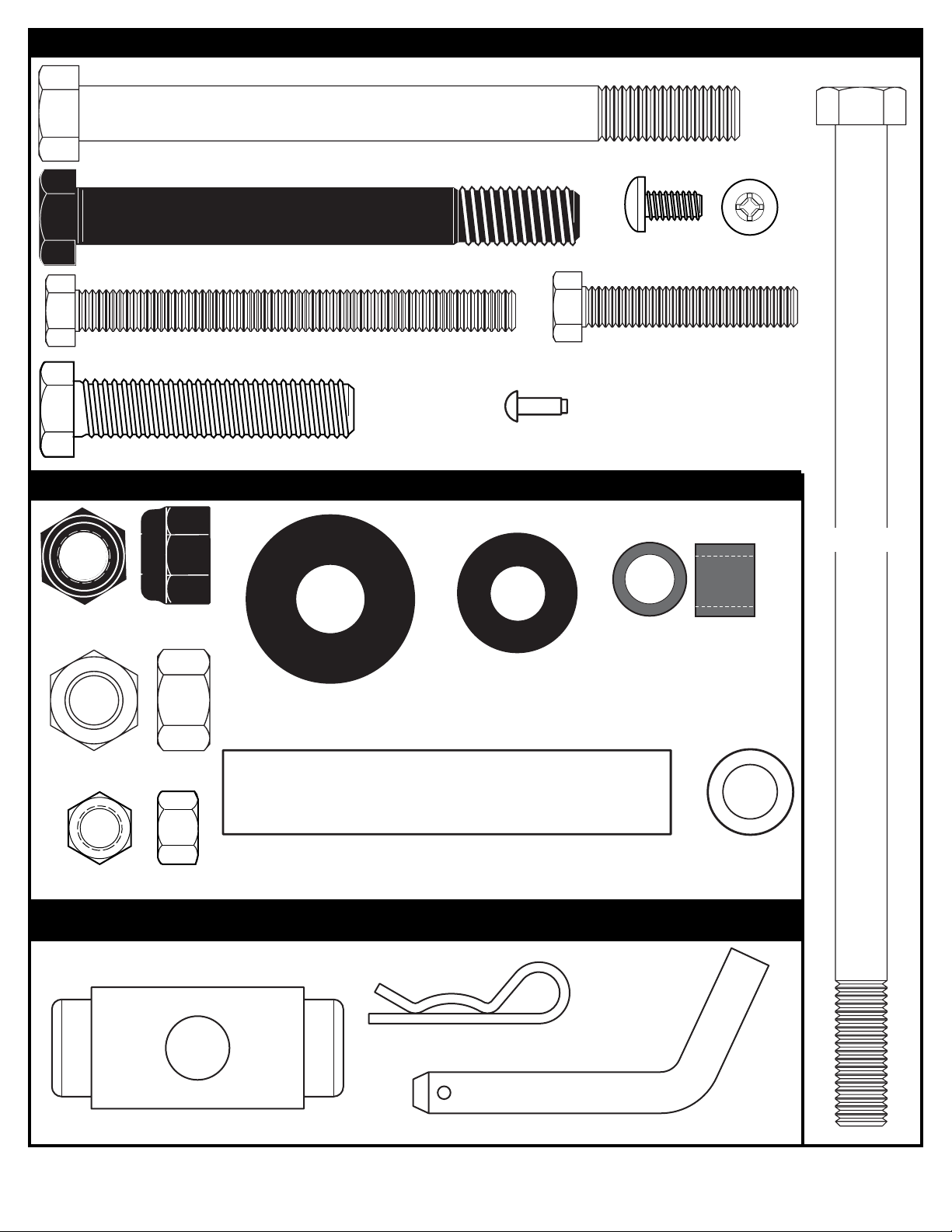
HARDWARE IDENTIFIER (BOLTS & SCREWS)
Item #34 (4)
Item #24 (9)
Item #21 (16)
Item #33 (4)
Item #7 (2)
Item #8 (2)
Item #26 (1)
Item #29 (4)
Item #28 (3)
Item #20 (1)
Item #23 (1)
Item #25 (13)
Item #22 (10)
Item #36 (1)
HARDWARE IDENTIFIER (OTHER)
Item #37 (1)
HARDWARE IDENTIFIER (NUTS, WASHERS & SPACERS)
Page 5
5
05/05 ID# M866041
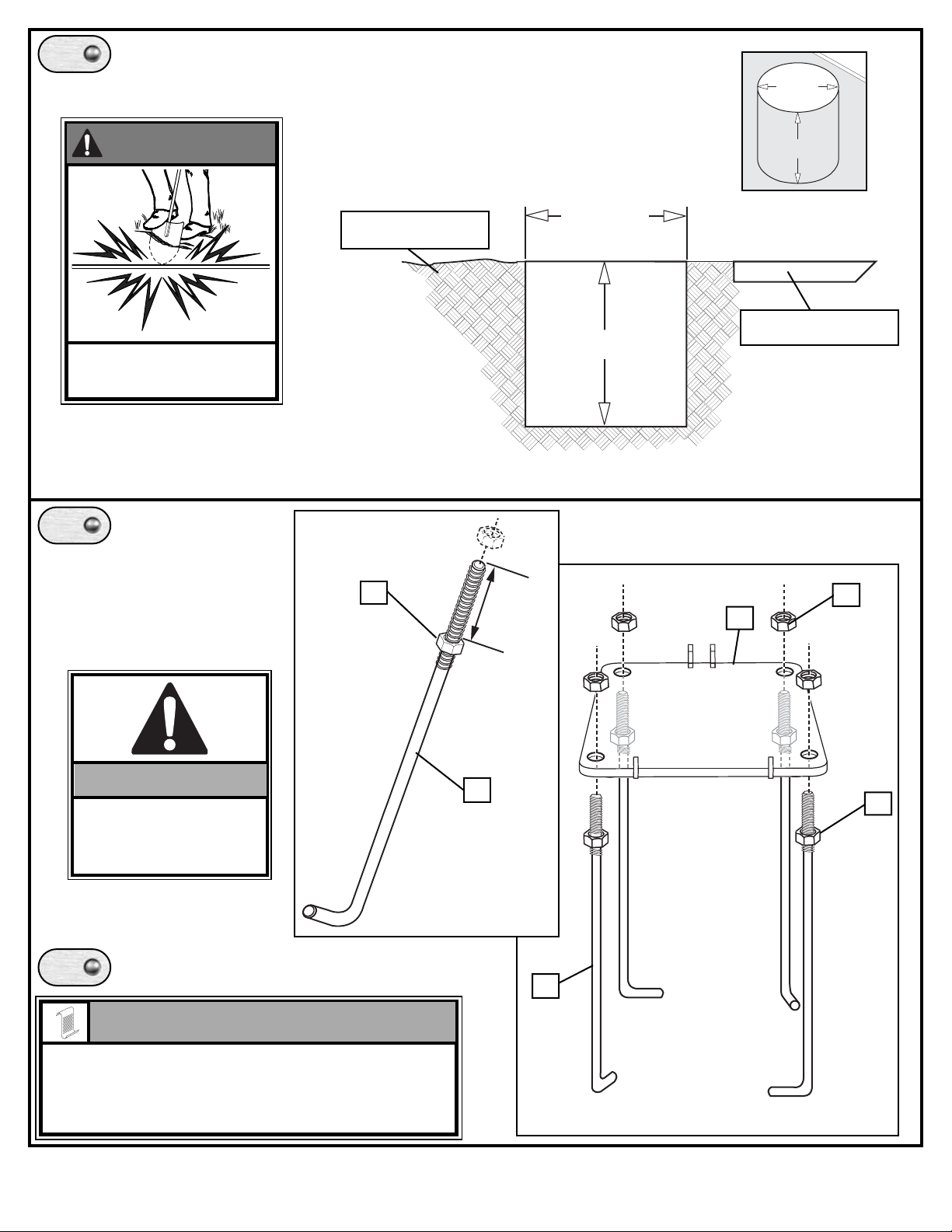
Ensure ground is level with playing surface, then dig pole hole.
Install threaded ends of J-bolts (19) through holes
in mounting plate (2) and secure as shown.
2
25
25
25
19
19
Install nut (25) to J-bolt (19)
as shown. Repeat procedure
for remaining three J-bolts
(19).
2.75”
(7 cm)
CONTACT UTILITIES
BEFORE DIGGING.
WARNING!
24" (61 cm)
48" (121.9 cm)
PLAYING SURFACE
GROUND SURFACE
24" (61 cm)
48" (121.9 cm)
IMPORTANT!:
Make sure nuts (25)
are 2.75” (7 cm) from
top of J-bolts
Make sure J-bolts (19) are in the illustrated position.
Nuts on the top of plate are used for leveling the pole after
system is fully assembled.
NOTE:
1.
3.
2.
Page 6
6
ID# M866041 05/05
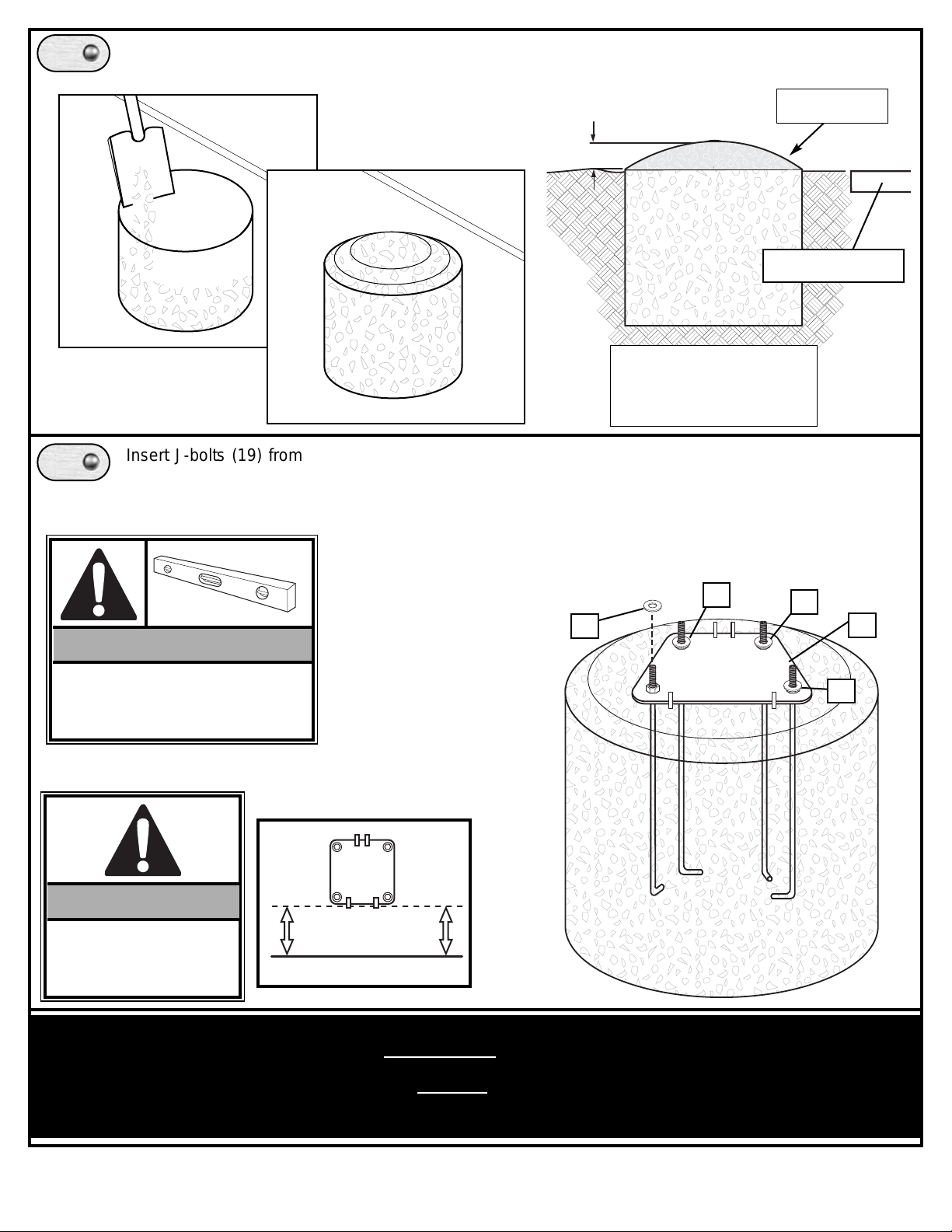
Insert J-bolts (19) from mounting plate (2) into cement as shown. Move assembly around to release
any air pockets in cement, then rest mounting plate on cement drainage hill. Apply some pressure to
level mounting plate on top of drainage hill. Level mounting plate and square with playing surface.
Clean off any excess cement on mounting plate at this time and place washers (24).
PLAYING SURFACE
SIDE VIEW
DRAINAGE HILL
PLAYING SURFACE
Fill hole with concrete. Tamp down concrete to release air pockets
and build drainage hill.
IMPORTANT!: WAIT A MINIMUM OF 72 HOURS BEFORE GOING ON
TO NEXT STEP. CONCRETE MUST
CURE. ALLOW ADDITIONAL TIME
FOR COLD, WET OR HUMID WEATHER.
IMPORTANT!:
Front of mounting plate
(2) must be parallel with
playing surface.
2
IMPORTANT!:
Check leveling of mounting plate
several times with carpenter’s level
while concrete is curing.
4.
5.
24
24
24
24
1" (2.54 cm)
Page 7
7
05/05 ID# M866041
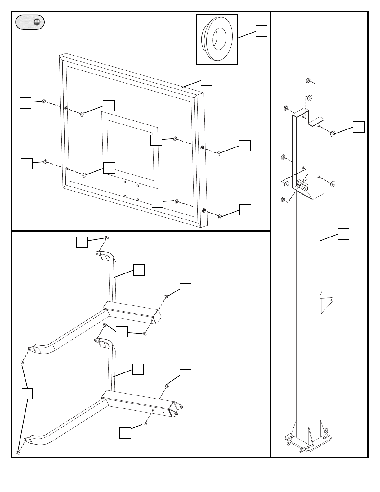
Insert bushings (27) into areas
shown.
27
27
1
10
27
27
17
18
27
27
27
27
27
6.
27
27
27
27
27
27
27
Page 8
8
ID# M866041 05/05
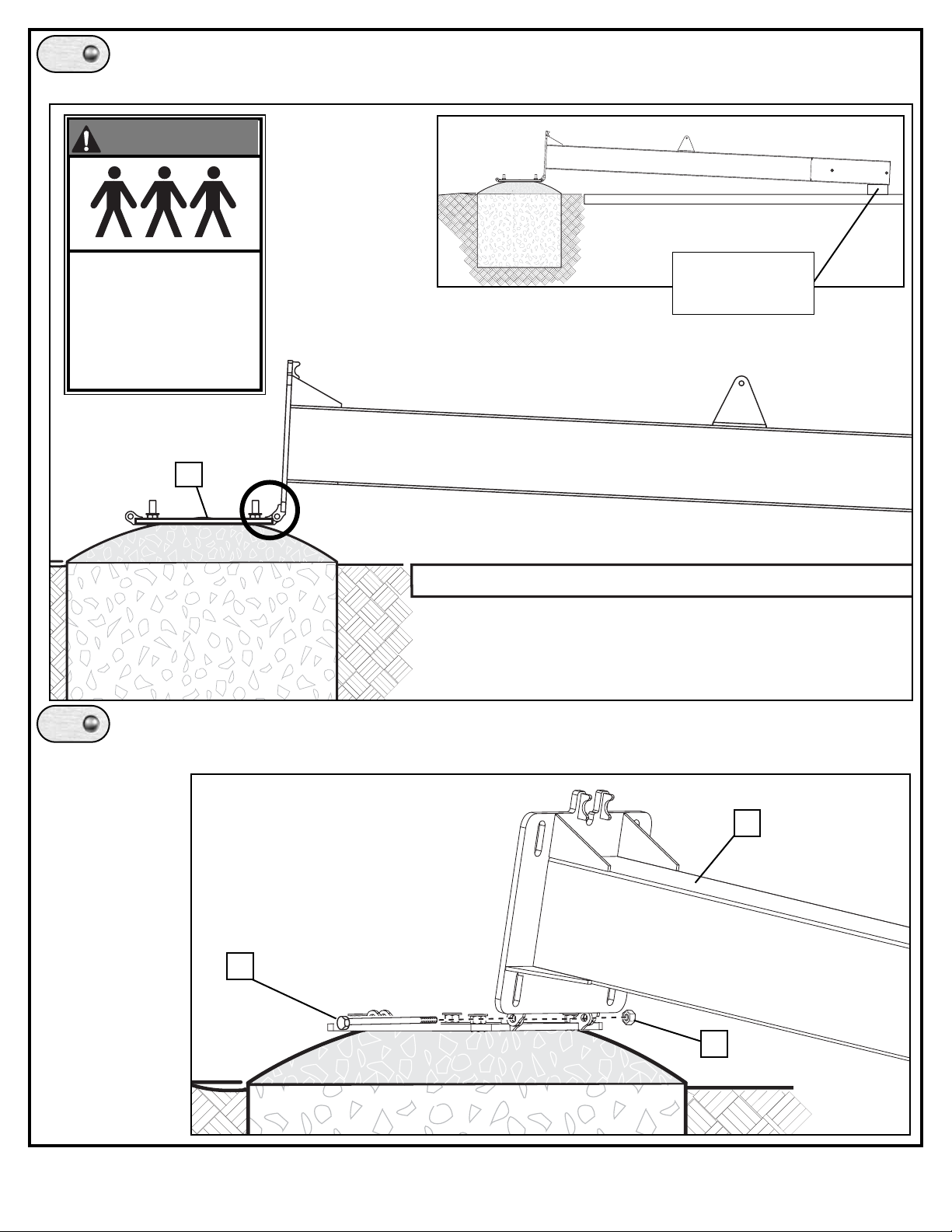
Rest top of pole on a piece of scrap wood (not included) and line up holes in pole to holes in
mounting plate (2) as shown.
7A.
22
15
1
PLAYING SURFACE
2
Insert bolt (15) through holes in plate and pole and secure with nut (22).
7B.
SCRAP WOOD
(NOT INCLUDED)
THREE PEOPLE
REQUIRED FOR THIS
PROCEDURE. FAILURE
TO FOLLOW THIS
WARNING COULD RESULT
IN SERIOUS INJURY
AND/OR PROPERTY
DAMAGE.
WARNING!
PLAYING SURFACE
Page 9
9
05/05 ID# M866041
THREE PEOPLE
REQUIRED FOR THIS
PROCEDURE. FAILURE
TO FOLLOW THIS
WARNING COULD RESULT
IN SERIOUS INJURY
AND/OR PROPERTY
DAMAGE.
WARNING!
8.
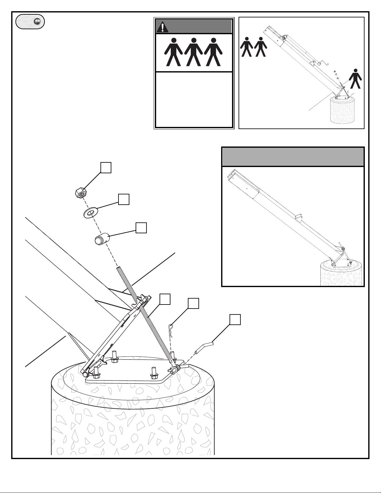
TWO people are required to lift pole into
position so that the rod (14) can be installed
and secured by the THIRD person.
While pole is being supported by TWO
capable adults, position rod (14) and lock
into place with hitch pin (36) and cotter
pin (37).
Slide barrel washer (35) onto other end of
rod (14) and secure with washer (24) and
nut (25). Tighten until locked into completed
assembly position
25
24
35
37
36
14
Completed Assembly
Page 10
10
ID# M866041 05/05
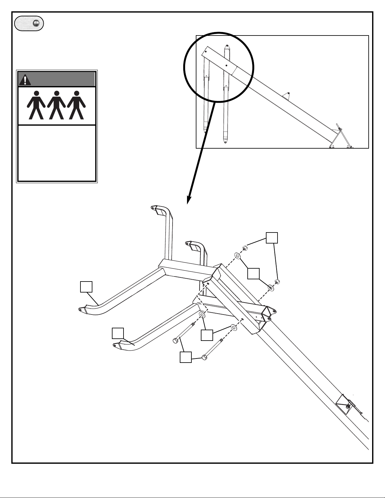
While still in forward position, attach both upper
and lower yokes (17 & 18) to pole as shown.
9.
22
21
28
21
17
18
THREE PEOPLE
REQUIRED FOR THIS
PROCEDURE. FAILURE
TO FOLLOW THIS
WARNING COULD RESULT
IN SERIOUS INJURY
AND/OR PROPERTY
DAMAGE.
WARNING!
Page 11
11
05/05 ID# M866041
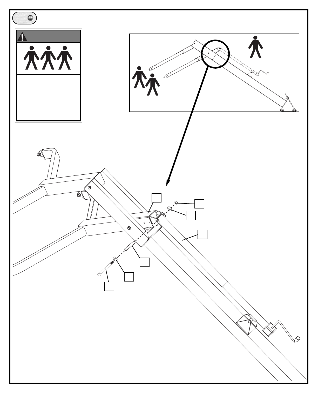
Attach elevator adjustment (12) to
lower yoke (18).
10.
THREE PEOPLE
REQUIRED FOR THIS
PROCEDURE. FAILURE
TO FOLLOW THIS
WARNING COULD RESULT
IN SERIOUS INJURY
AND/OR PROPERTY
DAMAGE.
WARNING!
22
12
21
20
18
26
21
Page 12
12
ID# M866041 05/05
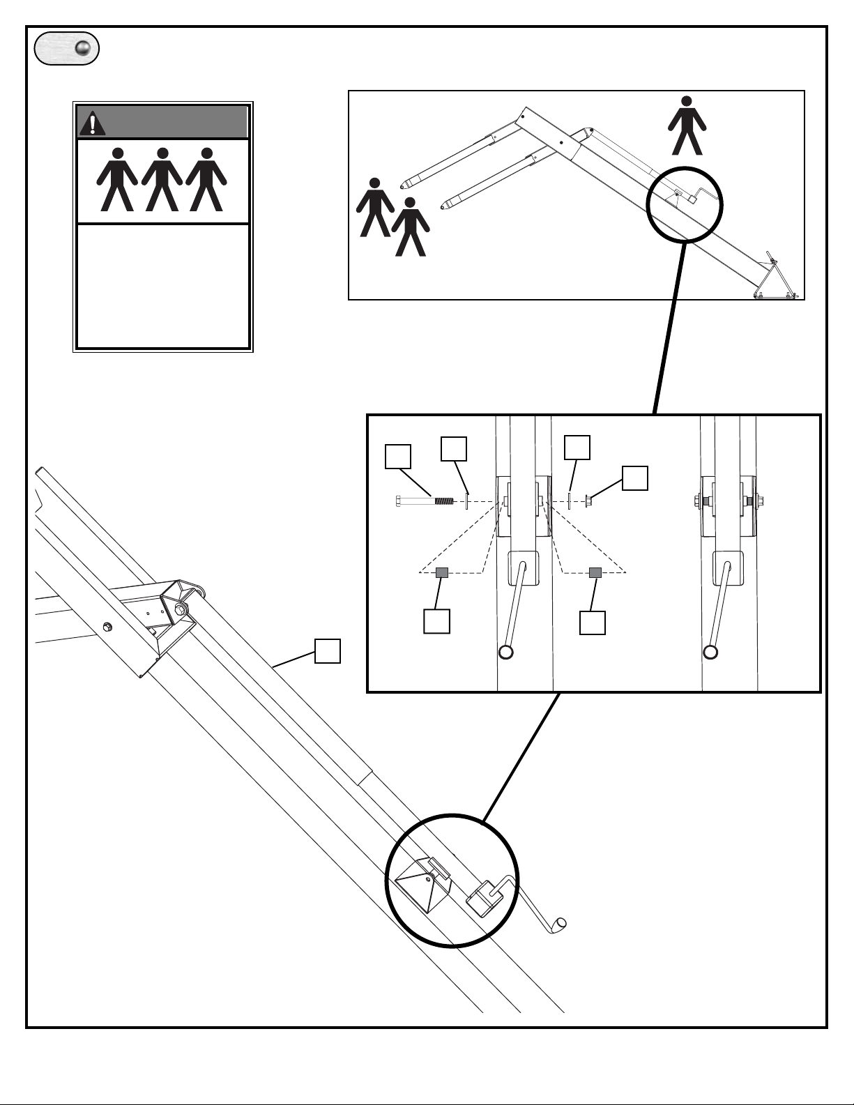
Attach elevator adjustment (12) to pole bracket.
11.
THREE PEOPLE
REQUIRED FOR THIS
PROCEDURE. FAILURE
TO FOLLOW THIS
WARNING COULD RESULT
IN SERIOUS INJURY
AND/OR PROPERTY
DAMAGE.
WARNING!
12
23
21
22
33
33
21
Page 13
13
05/05 ID# M866041
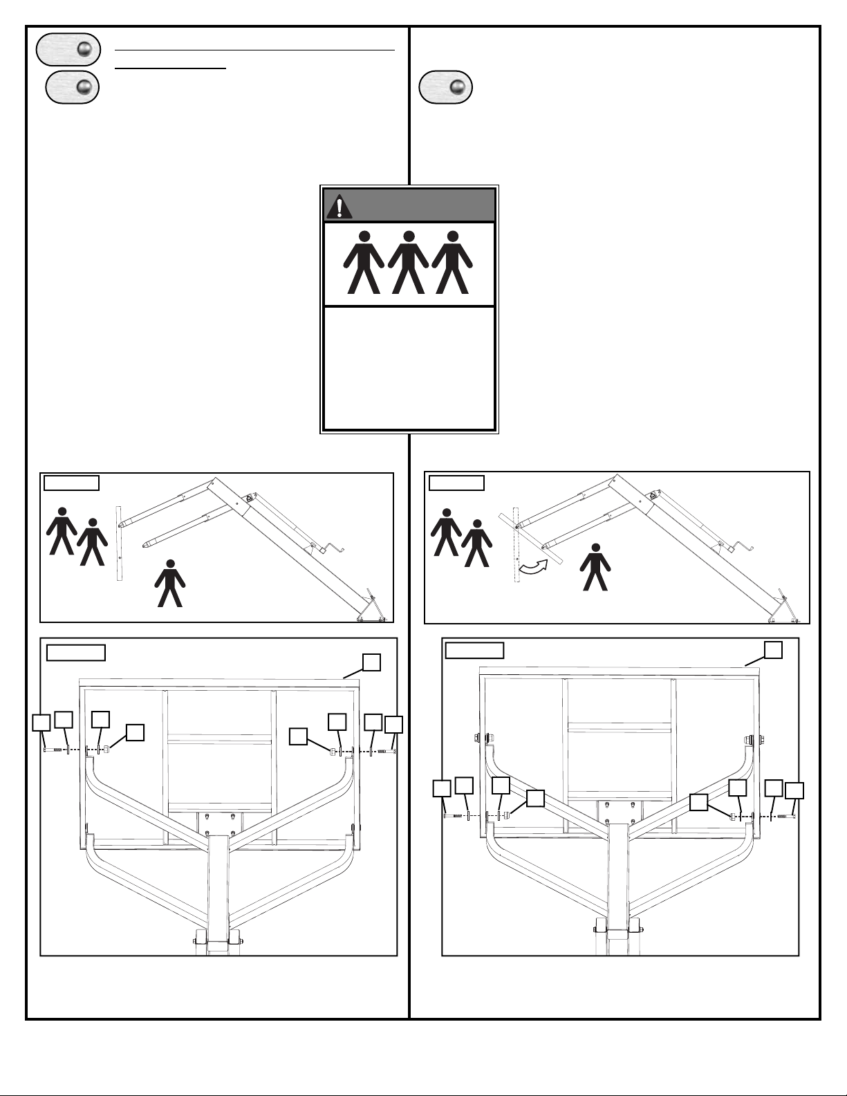
Attach backboard (10) to upper and lower
yokes (18 & 17).
First attach board (10) to upper yoke (17),
using TWO people to hold the board and
ONE person to attach hardware (FIG. A).
Use hardware as shown in FIG. B.
12.
A.
FIG. A
FIG. C
Then, hinge board to match up with holes in
lower yoke (18), FIG. C, and secure with
hardware as shown in FIG. D.
21
22
21
10
FIG. B
22
21
21
34
34
21
22
21
FIG. D
22
21
21
34
34
THREE PEOPLE
REQUIRED FOR THIS
PROCEDURE. FAILURE
TO FOLLOW THIS
WARNING COULD RESULT
IN SERIOUS INJURY
AND/OR PROPERTY
DAMAGE.
WARNING!
B.
10
Page 14
14
ID# M866041 05/05
13.
5
8
Refer To Instructions
Included With Rim
Hardware For Rim
Assembly.
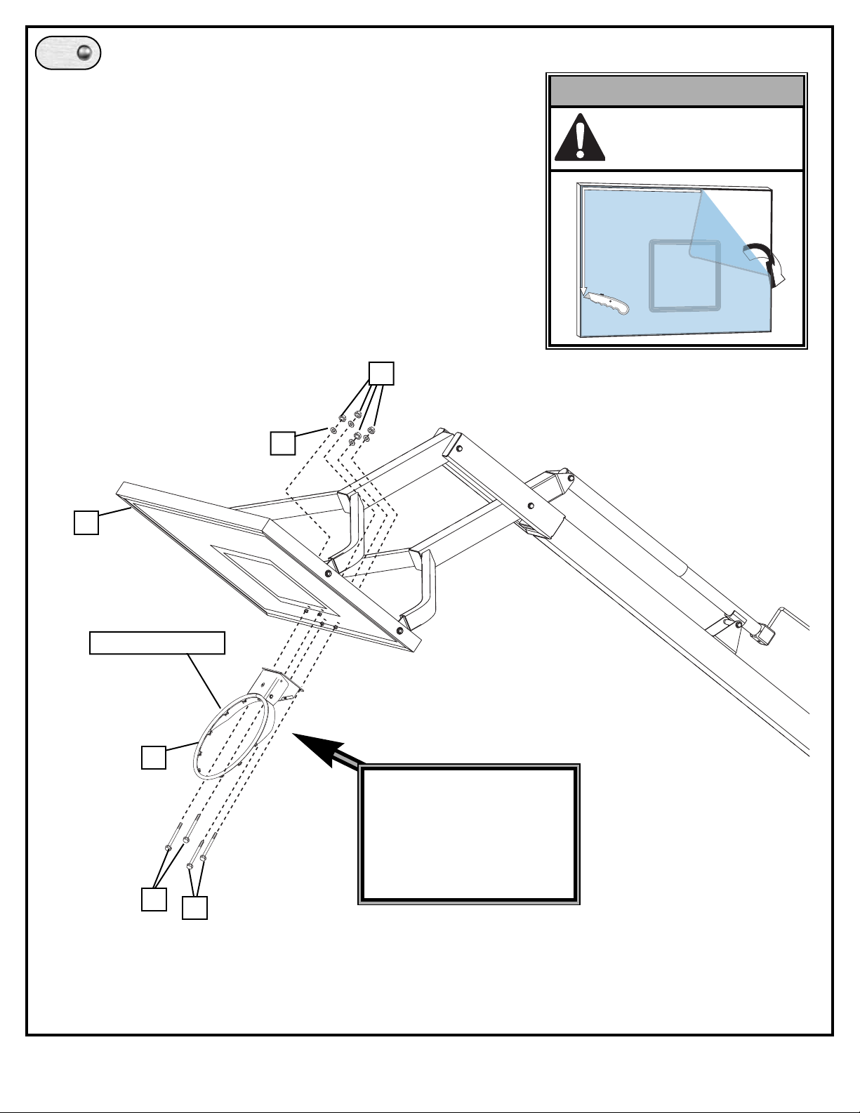
Remove rim cover (16), attach rim assembly (3) to backboard (10) and
reattach rim cover (16).
** For rim assembly see instructions included with rim.
3
Rim Assembly
6
10
7
IMPORTANT!:
Carefully cut and peel
protective film away from
board prior to attaching rim.
Page 15
15
05/05 ID# M866041
14.
A.
B.
15.
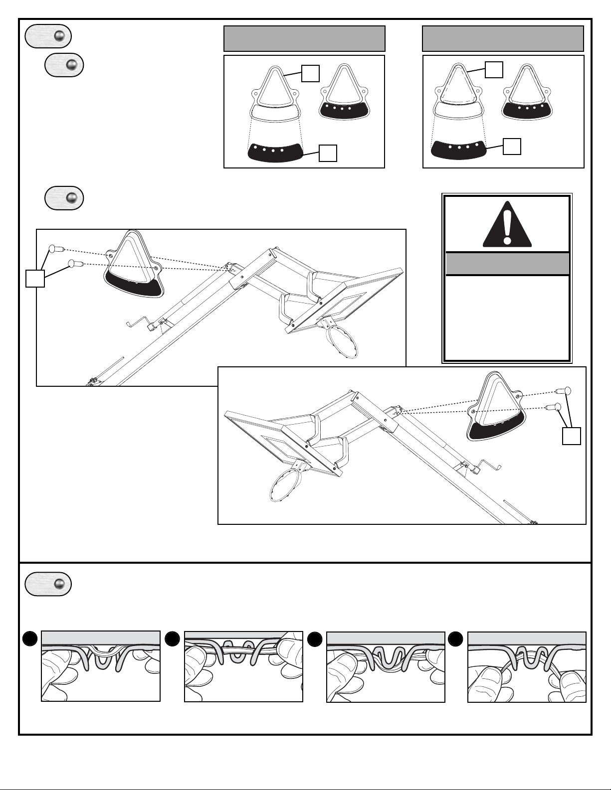
Apply height indicator
labels (32 & 31) to height
indicators (30).
Attach height indicators to lower yoke in area shown by tapping
screws (29) into place with a rubber mallet.
2.
4.
3.
1.
Install net (4) to rim as shown.
IMPORTANT!:
NOTE ORIENTATION
OF HEIGHT
INDICATORS:
10’ MARK SHOULD
FACE AWAY FROM
BACKBOARD.
Set-up For Right SideSet-up For Left Side
29
29
32
31
30
30
10
9
78
10
9
78
10
9
8
7
7
8
10
9
7
8
10
9
10
9
8
7
Page 16
16
ID# M866041 05/05
7
PLAYING
SUR
F
ACE
WAR
NING
F
AILURE
T
O
FOLLO
W
THESE
W
ARNINGS
MA
Y
RESUL
T
IN
SERIOUS
INJUR
Y
AND/OR
PR
OPER
TY
D
AMA
GE.
Owner
m
ust
ensure
that
all
pla
y
er
s
kno
w
and
f
ollow
these
rules
f
or
saf
e operation
of
the
system.
•
See
instruction
man
ual
f
or
pr
oper
installation.
•
DO
NO
T
HANG
on
the
rim
or
an
y par
t
of
the
system
inc
luding
bac
kboar
d,
suppor
t
braces
or
net.
•
During
pla
y
,especiall
y
when
perf
orming
dunk
type
activities,
keep
pla
y
er's
face
a
wa
y
fr
om
the
bac
kboar
d,
rim
and
net.
Serious
injur
y could
occur
if
teeth/face
come
in
contact
with
bac
kboar
d,
rim
or
net.
•
Do
not
slide
,
c
limb,shake
or
pla
y
on
pole
.
•
When
adjusting
height,
keep
hands
and
fing
er
s
a
wa
y
fr
om
mo
ving
par
ts.
•
Do
not
allo
w
c
hildren
to
mo
ve
or
adjust
system.
•
During
pla
y
,do
not
wear
je
welr
y
(rings,
watc
hes,
nec
klaces,
etc.);
objects
ma
y
entangle
in
net.
•
K
eep
or
ganic
material
a
wa
y
fr
om
pole
base
.
Grass,
litter
,
etc.
could
cause corr
osion
and
or
deterioration.
•
Check pole
system
f
or
signs
of
corr
osion
(rust,
pitting,
c
hipping)
and
repaint
with
with
exterior
enamel
paint.
If
rust
has
penetrated
thr
ough the
steel
an
ywhere
,
replace
the
pole
immediatel
y
.
•
Check
system
bef
ore
eac
h
use
f
or
pr
oper
ballast,loose
har
d
ware
,
e
xcessive
wear
and
signs
corr
osion
and
repair
bef
ore
using.
•
Check
system
bef
ore
eac
h
use
f
or
instability
.
•
Ne
ver
pla
y
on
dama
g
ed
equipment.
•
K
eep
pole
top
co
vered
with
cap
at all
times.
201255
2/99
1-800-558-5234
1
25
24
16.
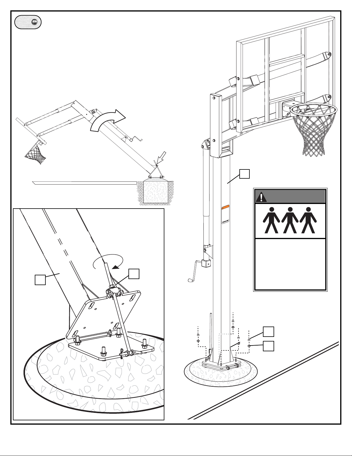
Upright pole (1) by tightening nut (25).
Using 3/4” wrench, turn nut (25) clockwise to
begin standing pole upright. Continue to turn
nut (25) until pole has come to rest against
washers (24) and pole is vertical.
Once pole is in its final position, install
washers (24) and nuts (25) onto J-bolts (19)
and fully tighten to secure pole to base plate
1
25
THREE PEOPLE
REQUIRED FOR THIS
PROCEDURE. FAILURE
TO FOLLOW THIS
WARNING COULD RESULT
IN SERIOUS INJURY
AND/OR PROPERTY
DAMAGE.
WARNING!
Page 17
17
05/05 ID# M866041
17.
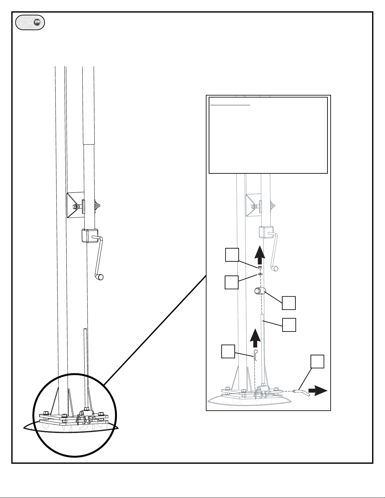
After pole has been secured to plate (2) loosen nut
(25), remove cotter pin (37), and pull out pin (36). This
will allow the removal of the assembly bolt (14) which
is no longer necessary for the remainder of the
assembly and installation of system.
WARNING: ONLY AFTER NUTS
(24) HAVE BEEN FULLY
TIGHTENED:
Remove cotter pin (37) and pin
(36) to remove assembly
bolt (14) from bottom plate (2).
35
37
36
24
25
14
Page 18
18
ID# M866041 05/05
12
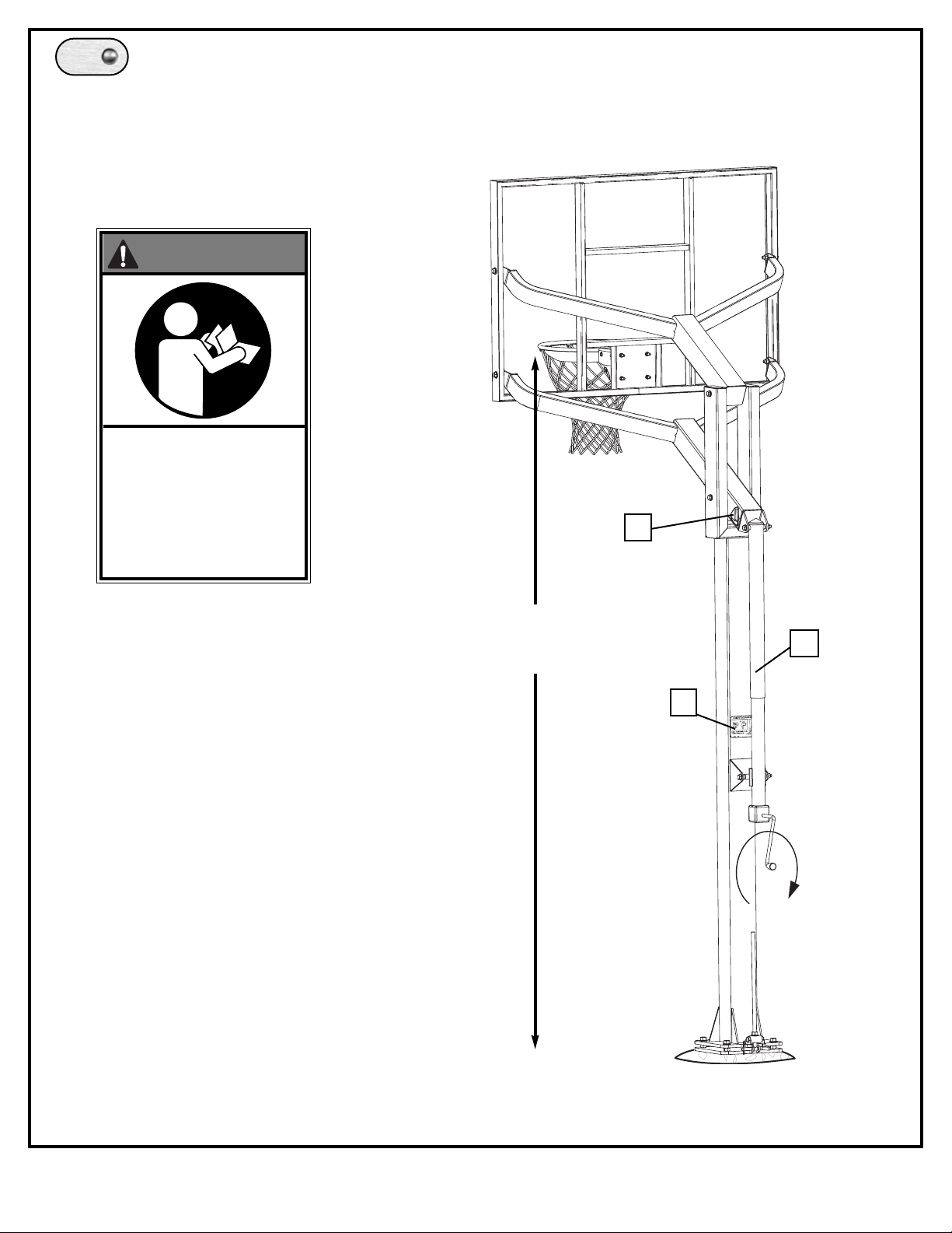
18.
Apply height adjust ment label (11).
Adjust system by turning crank until desired
height is reached per height indicator (30).
11
30
10 feet
(3.05 m)
READ AND UNDERSTAND
WARNING & HEIGHT
ADJUSTMENT LABELS
BEFORE USING THIS UNIT.
FAILURE TO FOLLOW
OPERATING INSTRUCTIONS
COULD RESULT IN INJURY
OR DAMAGE TO PROPERTY.
WARNING!
Page 19

19
05/05 ID# M866041
Subject to proper installation and normal use, Hydra-Rib
®
warrants, subject to limitations below, to the original retail
purchaser all structural components of the Hydra-Rib
®
system to be free of defects in material and workmanship
for the duration of ownership by the original retail
purchaser.
Mercahndise must be shipped prepaid with a copy of proof
of purchase to our factory for examination to see whether
it needs to be repaired or replaced. Any labor costs,
travel expenses and any other charges involved in the
removal, installation or replacement of the
defective/repaired partsfrom/to your Hydra-Rib
®
system
will be your (the purchaser’s) responsibilty. Shipping
chargesfor replacedor warranted merchandise being
sent back to the customer from our factory must be
prepaid by the customer in advance. If not, the
replacement shipment will be sent out collect.
What is Not Covered By This Warranty
Paint or rusted parts. Paint kits will be available to assist in
normal maintenace.
RIM
HANGING ON THE RIM WILL VOID YOUR WARRANTY.
RIms are not warranted for any defects other than
workmanship. Torn back plates, damaged springs, bent
rings, damaged eye bolts, and torn or distorted rim
supports result from hanging on the rim and are not
warranted.
LIMITED LIFETIME WARRANTY
 Loading...