

Page 1
1
02/04 P/N 211789
© COPYRIGHT 2004 by HUFFY SPORTS
Toll-Free Customer Service Number for U.S: 1-800-558-5234,
For Canada: 1-800-284-8339,
For Europe: 00 800 555 85234 (Sweden: 009 555 85234),
For Australia: 1-800-632-792
Internet Address: www.huffysports.com
HUFFY
REQUIRED TOOLS AND MATERIALS:
• Two People
• Wood Board (Scrap)
• Tape Measure
• Step Ladder 8 ft. (2.4 m)
• Tape
• Garden Hose or Sand 360 lb. (163 kg)
• Hammer
• Wrenches: (Two) 3/4”, (One) 1/2” (Two) 9/16”or
equivalent sockets, (One) 1/2” Deep well socket
with extension and socket wrench
• Support Table
• Phillips Head Screwdriver
• 5/32 Allen Wrench
Portable Basketball System
Owners Manual
Customer Service Center
• N53 W24700 South Corporate Circle • Sussex, WI 53089 • U.S.A.
READ AND UNDERSTAND
OPERATOR'S MANUAL
BEFORE USING THIS UNIT.
FAILURE TO FOLLOW
OPERATING INSTRUCTIONS
COULD RESULT IN INJURY
OR DAMAGE TO PROPERTY.
WARNING!
HU
FFY
SPORTS
Page 2
2
P/N 211789 02/04
WARNING
FAILURE TO FOLLOW THESE WARNINGS MAY RESULT
IN SERIOUS INJURY AND/OR PROPERTY DAMAGE.
Owner must ensure that all players know and follow
these rules for safe operation of the system.
• DO NOT HANG on the rim or any part of the system
including backboard, suppor t braces or net.
• During play, especially when performing dunk type
activities, keep player's face away from the backboard, rim
and net. Serious injury could occur if teeth/face come in
contact with backboard, rim or net.
• Do not slide, climb, shake or play on base and/or pole.
• After assembly is complete, fill system completely with
water or sand and stake to the ground. Never leave system
in an upright position without filling base with weight, as
system may tip over causing injuries.
• When adjusting height or moving system, keep hands and
fingers away from moving parts.
• Do not allow children to move or adjust system.
• During play, do not wear jewelry (rings, watches, necklaces,
etc.). Objects may entangle in net.
• Surface beneath the base must be smooth and free of
gravel or other sharp objects. Punctures cause leakage and
could cause system to tip over.
• Keep organic material away from pole base. Grass, litter,
etc. could cause corrosion and/or deterioration.
• Check pole system for signs of corrosion (rust, pitting,
chipping) and repaint with exterior enamel paint. If rust has
penetrated through the steel anywhere, replace pole
immediately.
• Check system before each use for proper ballast, loose
hardware, excessive wear and signs corrosion and repair
before use.
• Check system before each use for instability.
• Do not use system during windy and/or severe weather
conditions; system may tip over. Place system in the
storage position and/or in an area protected from the wind
and free from personal property and/or overhead wires.
• Never play on damaged equipment.
• See instruction manual for proper installation and
maintenance.
• When moving system, use caution to keep mechanism from
shifting.
• Keep pole top covered with cap at all times.
• Do not allow water in tank to freeze. During sub-freezing
weather add non-toxic antifreeze, sand or empty tank
completely and store. (Do not use salt.)
•
While moving system, Do not allow anyone to stand or sit
on base or have added ballasting on base.
• Do not leave system unsupervised or play on system when
wheels are engaged for moving.
• Use Caution when moving system across uneven surfaces.
System may tip over.
• Use extreme caution if placing system on sloped surface.
System may tip over more easily.
201246 2/99
In the U.S.:1-800-558-5234 and Canada: 1-800-284-8339
Page 3
02/04 P/N 211789
3
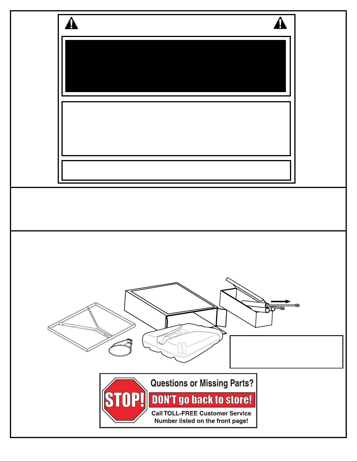
IMPORTANT!
Remove all contents from boxes.
Be sure to check inside pole sections;
hardware and additional parts are packed inside.
NOTICE TO ASSEMBLERS
ALL Huffy Sports basketball systems, including those used for DISPLAYS, MUST be assembled
and ballasted with sand or water according to instructions. Failure to follow instructions could
result in SERIOUS INJURY. It is NOT acceptable to devise a makeshift weight system.
SAFETY INSTRUCTIONS
FAILURE TO FOLLOW THESE SAFETY INSTRUCTIONS MAY RESULT IN SERIOUS INJURY OR
PROPERTY DAMAGE AND WILL VOID WARRANTY.
Owner must ensure that all players know and follow these rules for safe operation of the system.
To ensure safety, do not attempt to assemble this system without following the instructions carefully. Proper
and complete assembly, use, and supervision are essential for proper operation and to reduce the risk of
accident or injury. A high probability of serious injury exists if this system is not installed, maintained, and
operated properly.
• If using a ladder during assembly, use extreme caution.
• Check base regularly for leakage. Slow leaks could cause the system to tip over
unexpectedly
• Seat the pole sections properly (if applicable). Failure to do so could allow the pole
sections to seperate during play and/or during transport of the system.
• Climate, corrosion or misuse could result in system failure.
• If technical assistance is required, contact Huffy Sports.
• Minimum operational height is 6'-6" (1.98m) to the bottom of backboard.
Most injuries are caused by misuse and/or not following instructions.
Use caution when using this unit.
WARRANTY CARD:
Please remember to complete your product
registration form either on-line at:
www.huffysports.com/warrantycard or mail-in
the enclosed postcard.
Page 4
4
P/N 211789 02/04
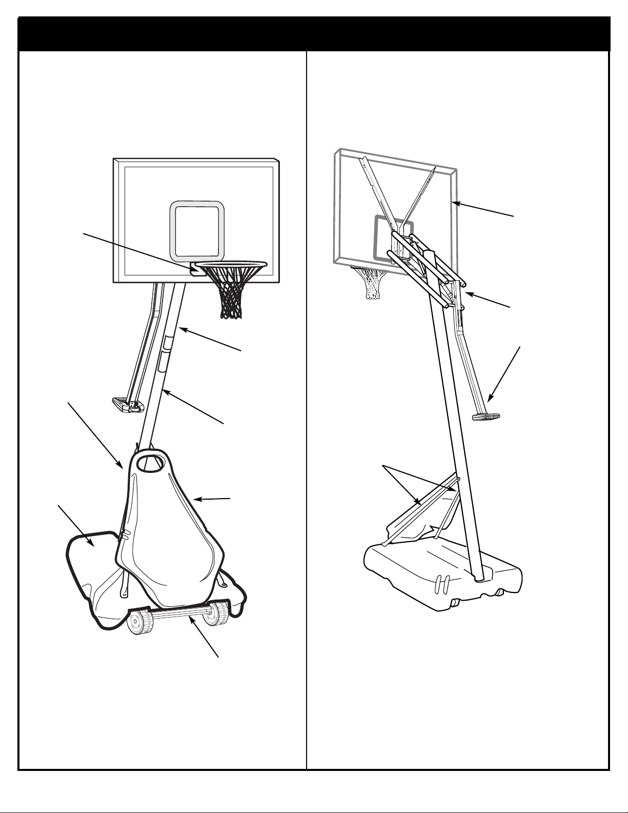
Get to know the basic parts of your basketball system.....
FRONT
TOP POLE
BACK
MIDDLE POLE
FRONT
COVER
RIM
BOTTOM
POLE
STRUTS
ELEVATOR
ASSEMBLY
BACKBOARD
BASE
WHEEL
CARRIAGE
ASSEMBLY
Page 5
02/04 P/N 211789
5
ItemQty Part No Description
1 1 900467 Top Pole Section
2 1 904811 Middle Pole Section (with Label)
3 1 903407 Bottom Pole Section
4 2 900223 Wheel Bracket
5 2 206940 Axle
6 2 226403 Wheel 6”
7 4 206938 Pushnut
8 1 200117 Base
9 1 203223 Carriage Bolt, 5/16-18 x 1
10 1 202662 Hex Bolt, 5/16-18 x 4.5
11 8 203218 Washer 5/16
12 1 200188 Rod 3/8 x 5.25
13 1 202822 EyeBolt 3/8 -16 x 3.75
14 2 906410 Tank Strut
15 1 200516 Bolt Cover
16 1 200123 Upper Pivot Bracket
17 1 206948 Lower Pivot Bracket
18 2 900122 Hinge Tubes
19 1 200512 Hex Bolt, 3/8 -16 x 3.5
20 4 203232 Flat Washer 3/8 -3/4
21 1 206252 Hex Bolt, 3/8 -16 x 1
22 13 203100 Flange Nut 5/16 -18
23 1 203330 Hex Bolt, 3/8 -16 x 4.5
24 2 203527 Spacer, Plastic, .75" O.D., 1.53" Long
25 2 203528 Spacer, Plastic, 1.25" O.D., 1.53" Long
26 4 203103 Carriage Bolt, 5/16-18 x 2
27 1 203540 Height Indicator Window
28 1 201129 Spacer, Metal, .50" O.D., 1.8" Long
29 1 803531 Strut Assembly
30 1 803553 Handle Assembly
31 1 203593 Shoulder Bolt
32 2 203688 Spacer, Plastic, .75" O.D., 2.25" Long
33 2 900867 Triangle Plates
ItemQty Part No Description
34 1 207103 Pole Cap
35 4 908119 Elevator Tube
36 1 808115 Pole Bracket
37 9 206340 Nut, Nylock, 1/2 -13
38 2 203053 Bolt, Carriage, 5/16-18 x 4
39 4 202862 Spacer, Plastic, .50 O.D., 1.19" Long
40 8 204847 Bolt 1/2 -13 x 9.5
41 1 201139 Bolt 1/2 -13 x 4.5
42 4 201682 Spacer, Plastic, .50 O.D., 1.88" Long
43 2 203798 Bolt 5/16-18 x 1.5
44 2 202273 Spacer, Metal, .50 O.D., 5-7/8" Long
45 1 203099 Nut, Nylock, 5/16-18
46 2 200874 Spacer, Metal, .50 O.D., 1.53" Long
47 3 206360 Bolt 3/8 -16 x 2.625
48 7 203063 Nut 3/8 -16 Nylock
49 2 900964 Board Brackets
50 1 200118 Front Cover
51 4 265601 Front Cover Carriage Bolts
52 12 201219 Net Clips
53 1 204290 Net
54 1 206219 Base Plug
55 1 203124 Tie Down Stake
56 1 201568 Anchor Strap
57 1 203532 Label Height Adjustment
58 2 240027 Nut, Nylock 1/4-20
59 1 203535 Strip
60 1 203536 Height Label
61 1 203537 Hook
62 1 240019 Bolt 1/4-20 x .75
63 2 202274 Spacer, Metal, .50 O.D., 3-1/2" Long
64 1 206956 Plastic Disc
65 2 226401 Wheel 4”
66 2 203309 Washer, Flat, 3/8-1
* You may have extra parts with this model.
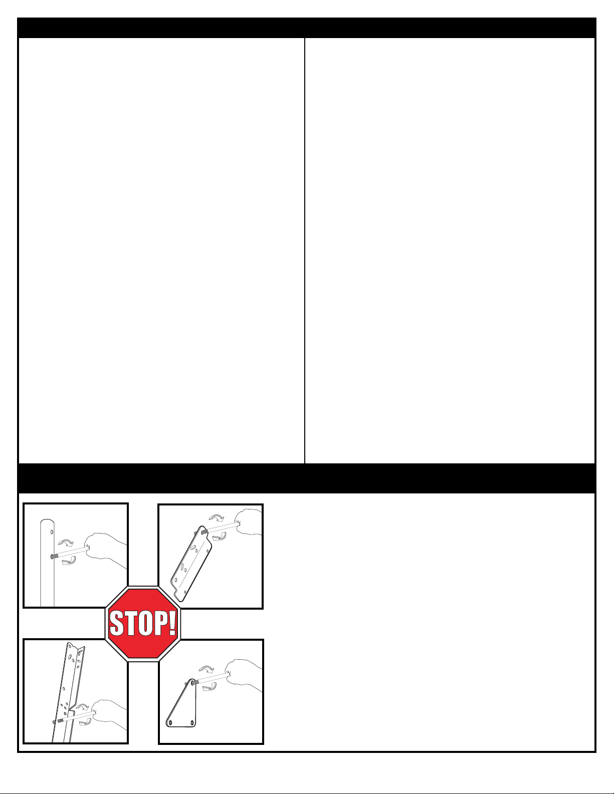
BEFORE YOU START!
To ensure optimal playability of backboard system, a
close tolerance fit between the elevator components
and hardware is required. Test-fit large bolts into large
holes of elevator tubes, backboard brackets, and
triangle plates. Carefully rock them in a circular motion
to ream out any excess paint from holes if necessary.
PARTS LIST (SEE HARDWARE IDENTIFIER)
Page 6
6
P/N 211789 02/04
Item #19 (1)
Item #23 (1)
Item #31 (1)
* You may have extra parts with this model.
Item #40 (8)
Item #41 (1)
Item #47 (3)
Item #62 (1)
Item #43 (2)
Item #13 (1)
Item #10 (1)
Item #21 (1)
Item #38 (2)
Item #51 (4)
Item #26 (4)
Item #9 (1)
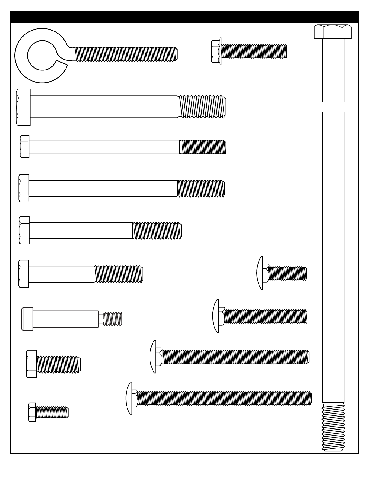
HARDWARE IDENTIFIER (BOLTS & SCREWS)
Page 7
02/04 P/N 211789
7
Item #42 (4)
Item #45 (1)
Item #46 (2)
Item #48 (7)
Item #58 (2)
Item #57 (1)
Item #11 (8)
Item #15 (1)
Item #37 (9)
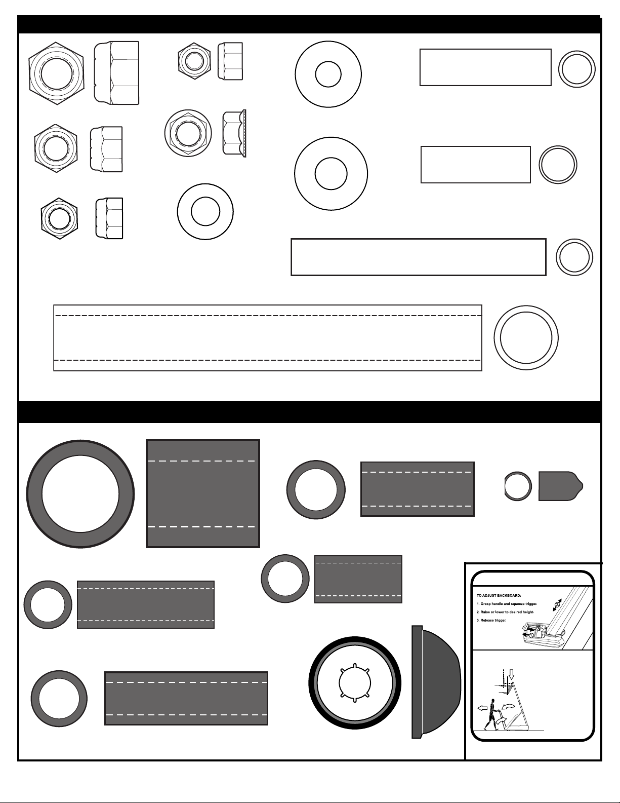
HARDWARE IDENTIFIER (NUTS, WASHERS & METAL SPACERS)
HARDWARE IDENTIFIER (LABELS, PLASTIC SPACERS & CAPS)
Item #32 (2)
Item #28 (1)
Item #25 (2)
Item #20 (4)
Item #24 (2)
Item #66 (2)
Item #22 (13)*
Item #63 (2)
Item #7 (4)
Item #39 (4)
Item #44 (2)
HEIGHT ADJUSTMENT
MOVING SYSTEM
1
2
3
4
1. Adjust basketball backboard
height to lowest position.
2. Rotate handleforward until
wheels engage ground.
3. Move basketball system to
desired location.
4. Rotate handle back to original
position.
5. Reattach ground restraint and
check system for stability.
203532 01/04
Page 8
8
P/N 211789 02/04
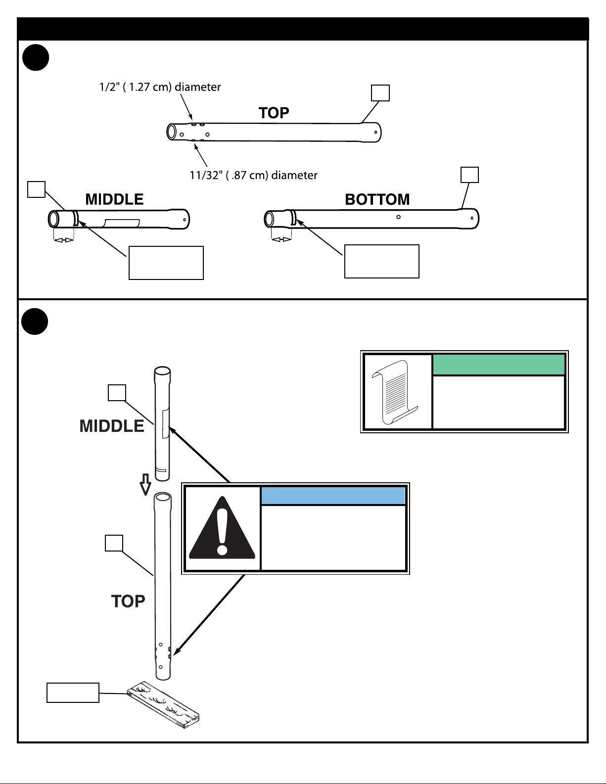
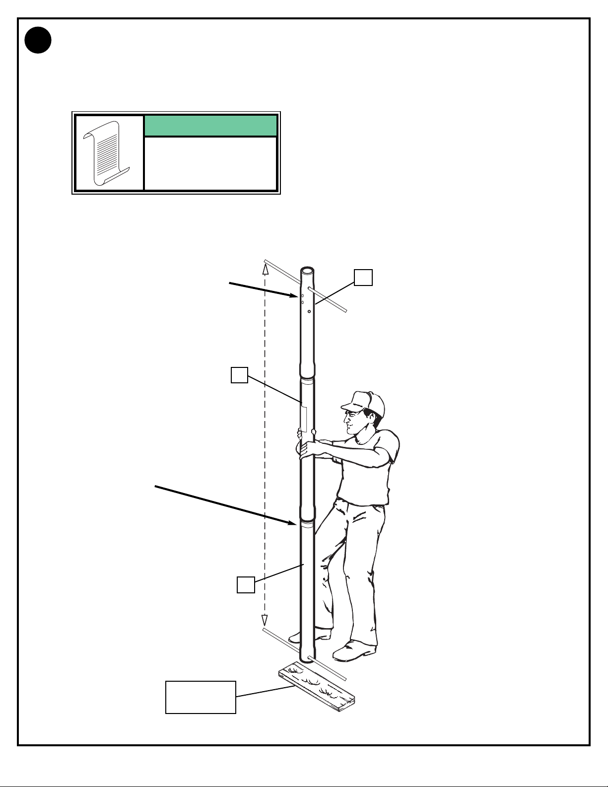
SECTION A: ASSEMBLE THE POLES
2.
1.
Wood Scrap
2
1
(
(13 cm)
1
3
2
Correctly identify each pole section. Mark pole sections with tape as shown.
TAPE
(not supplied)
TAPE
(not supplied)
Bounce middle pole section (2) into top pole section (1) together using a wood scrap as shown
until they no longer move toward taped reference mark.
IMPORTANT!:
Position middle pole so
that the warning label is on
the same side as the 11/32"
(.87cm) diameter holes of
the top pole.
POLE SECTIONS
SHOULD HAVE A
3-1/2" (9 CM) MINIMUM
OVERLAP.
NOTE:
5"
13 cm)
5"
Page 9
02/04 P/N 211789
9
IMPORTANT! Holes in top (1) and bottom pole (3) sections MUST align to correctly
position elevator system toward playing surface.
While maintaining alignment, bounce assembly and lower section (3) together as shown
until they no longer move toward taped reference mark.
1
2
3
3.
WOOD SCRAP
(NOT SUPPLIED)
TAPE REFERENCE
MARK
11/32" (.87 cm) SMALLER
DIAMETER HOLES OF
TOP POLE
POLE SECTIONS
SHOULD HAVE A
3-1/2" (9 CM) MINIMUM
OVERLAP.
NOTE:
Page 10
10
P/N 211789 02/04
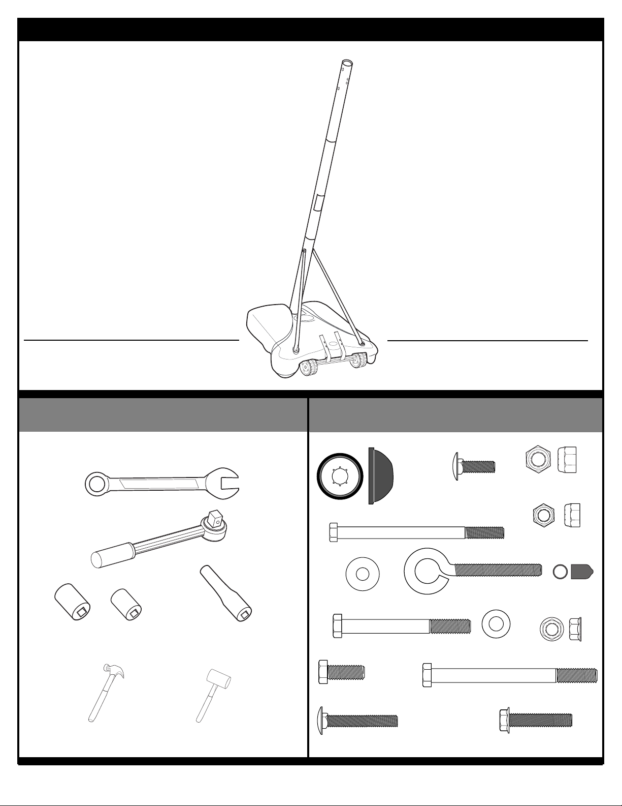
TOOLS REQUIRED FOR THIS SECTION
HARDWARE USED IN THIS SECTION
(not actual size)
SECTION B: ASSEMBLE THE BASE
1/2” & 9/16”
9/16” & 1/2” AND EXTENSION
HAMMER OR MALLET
AND
This is what your system will look like when
you’ve finished this section:
Item #7
Item #10
Item #11
Item #15
Item #19
Item #20
Item #21
Item #22
Item #23
Item #26
Item #13
Item #9
Item #43
Item #45
Item #48
Page 11

02/04 P/N 211789
11
1.
2.
Insert axle (5) through wheel bracket (4). Secure wheels (65) to axle using
pushnuts (7). Carefully tap pushnuts onto axle with hammer or mallet
4
65
65
7
7
5
Install wheel assembly to base (8) using bolt (9), and nut (22) as shown.
9
22
9
8
Page 12

12
P/N 211789 02/04
3.
Install rod (12) through holes in bottom pole section (3) and eyebolt (13).
Insert pole assembly into tank (8) and through center hole on wheel assembly as shown. Secure pole
assembly with anchor strap (56), washer (11), and lock nut (48).
13
12
1
3
2
48
12
13
8
11
56
TWO PEOPLE REQUIRED
FOR THIS PROCEDURE.
FAILURE TO FOLLOW THIS
WARNING COULD RESULT IN
SERIOUS INJURY AND/OR
PROPERTY DAMAGE.
WARNING!
IMPORTANT!:
Smaller holes (11/32"/ .87
cm) of top pole should
face toward the front of the
system and the warning
label should be facing
toward the front.
Page 13

02/04 P/N 211789
13
4.
10
11
11
45
14
3
15
14
14
Secure tank struts (14) to pole as shown.
Place cap (15) over exposed end of bolt as shown.
Rotate non-secured ends of tank struts (14) outward to mounting holes in
tank as shown.
TWO PEOPLE REQUIRED
FOR THIS PROCEDURE.
FAILURE TO FOLLOW THIS
WARNING COULD RESULT IN
SERIOUS INJURY AND/OR
PROPERTY DAMAGE.
WARNING!
Page 14

14
P/N 211789 02/04
5.
6.
Secure ends of tank struts (14) to tank as shown. Repeat for opposite side.
Install upper pivot bracket (16) to front of base using bolt (19), washer (20) and nut (48) as shown.
43
11
22
11
14
48
20
16
19
TWO PEOPLE REQUIRED
FOR THIS PROCEDURE.
FAILURE TO FOLLOW THIS
WARNING COULD RESULT IN
SERIOUS INJURY AND/OR
PROPERTY DAMAGE.
WARNING!
Page 15

02/04 P/N 211789
15
Insert bolt (21) through lower pivot bracket (17) as shown; bolt (21) will be
secured during step 10. Carefully place base assembly on its side. Install lower
pivot bracket (17) with bolt (23), washers (20), and lock nut (48) as shown.
Secure both hinge tubes (18) to second wheel bracket (4) with carriage bolts (26)
and flange nuts (22).
16
23
20
17
21
20
48
26
4
22
18
7.
8.
IMPORTANT!:
DO NOT OVER
TIGHTEN
Page 16

16
P/N 211789 02/04
Position base as shown. Secure wheel bracket assembly with
disc (64), washer (20) and nut (48) as shown.
7
6
5
4
6
7
21
64
20
48
Carefully reposition entire assembly as shown:
9.
10.
SIDE OF WHEEL WITH
LONGER PLASTIC
AXLE NEEDS TO FACE
THE WHEEL BRACKET.
IMPORTANT!:
TWO PEOPLE REQUIRED
FOR THIS PROCEDURE.
FAILURE TO FOLLOW THIS
WARNING COULD RESULT IN
SERIOUS INJURY AND/OR
PROPERTY DAMAGE.
WARNING!
Insert axle (5) through wheel bracket (4). Secure wheels (6) to axle using
pushnuts (7). Carefully tap pushnuts onto axle with hammer or mallet
IMPORTANT!:
DO NOT OVER
TIGHTEN
Page 17

02/04 P/N 211789
17
TOOLS REQUIRED FOR THIS SECTION
HARDWARE USED IN THIS SECTION
(not actual size)
SECTION C: ASSEMBLE THE ELEVATOR SYSTEM & BACKBOARD
WRENCHES
(2) 1/2”, (2) 3/4”
AND (2) 9/16”
This is what your system will look like when
you’ve finished this section:
Item #22
Item #37
Item #38
Item #39
Item #40
Item #41
Item #42
Item #46
Item #47
Item #48 (6)
Item #58
Item #62
AND (1) 5/32 Allen Wrench
Item #11
Item #31
Item #32
Item #28
Item #25
Item #44 (2)
Item #24
Item #66
1/2”, 9/16”, 3/4" & EXTENSION
AND/OR
Item #63
Page 18

18
P/N 211789 02/04
1.
Securely rest the assembly on sawhorse. Install pole bracket (36) to top pole as shown (FIG.A)
using bolts (38), metal spacers (63) and nuts (22). Reference finished assembly (FIG.B.)
FIG.A
36
38
22
63
63 & 38
22
36
FIG.B
FLAT SIDE
TOWARDS BASE.
COMPLETED ASSEMBLY
TWO PEOPLE REQUIRED
FOR THIS PROCEDURE.
FAILURE TO FOLLOW THIS
WARNING COULD RESULT IN
SERIOUS INJURY AND/OR
PROPERTY DAMAGE.
WARNING!
Page 19

02/04 P/N 211789
19
1
34
35
37
37
35
39
35
35
33
40
41
40
2.
Identify elevator tubes.
Install triangle plates (33) and elevator tubes (35) to top pole section (1) as shown.
Install pole cap (34) at this time.
33
35
Upper & Lower Elevator tube
Toward
Board
Toward
Pole
COMPLETED ASSEMBLY
39
39
Page 20

20
P/N 211789 02/04
3.
Attach label (60) to window (27).
Important: Line up top edge of label with top edge of window
COMPLETED
ASSEMBLY
COMPLETED ASSEMBLY
60
27
4.
Remove packaging materials and zip ties from handle assembly (30)
Snap window into handle assembly (30)
30
Page 21

02/04 P/N 211789
21
5.
Insert strut assembly (29) over inner channel (A) and between
outer channel (B). Rest at angle shown in fig. A. Line up holes
in strut bracket to holes in outer channel (B)
29
6.
Insert metal spacer (22) through outer channel (B), strut
bracket and inner channel (A). Center spacer on outer
channel.
NOTE:
To allow spacer to fit through, lift inner channel
(A) to help line up holes with outer channel (B).
Strut bracket
44
30B
30A
29
30B
30A
FIG. A
29
44
COMPLETED ASSEMBLY
DO NOT REMOVE CLIP
UNTIL SECTION F, STEP 1.
THIS CLIP PREVENTS
PREMATURE EXTENSION
OF GAS STRUT.
WARNING!
IMPORTANT!:
TO AVOID RAPID
EXTENSION OF STRUT
ROD - DO NOT DEPRESS
BUTTON ON GAS STRUT
ASSEMBLY.
COMPLETED ASSEMBLY
ORIENT STRUT ASSEMBLY
SO CLIP-HANDLE FACES
LONG SIDE OF CHANNELS
Page 22

22
P/N 211789 02/04
7.
Attach hook (59) to strip (61)
and secure with bolt (62) and
nut (58).
59
61
58
62
8.
Install hook and strip assembly into
handle assembly.
9.
Bring strip through top of height indicator window
(27) underneath tabs and insert through bottom
end of height indicator window (27).
IMPORTANT!:
STRIP(61) MUST PASS
UNDERNEATH ALL 6 TABS OF
HEIGHT INDICATOR WINDOW (27).
TABS
61
61
61
IMPORTANT!:
TO AVOID RAPID
EXTENSION OF STRUT
ROD - DO NOT DEPRESS
BUTTON ON GAS STRUT
ASSEMBLY.
Page 23

02/04 P/N 211789
23
35
11
10.
Attach strut (29) to pole
bracket (36) with bolt
(31), washers (11), and
nut (58) as shown.
11
58
11.
Slip plastic spacers (25) onto metal spacer (44) that is already inserted into handle
assembly. Then, secure handle assembly to elevator tubes (35) using bolts (40), plastic
spacers (24) and nuts (37).
31
36
35
25
25
37
40
40
24
24
37
44
29
IMPORTANT!:
TO AVOID RAPID
EXTENSION OF STRUT
ROD - DO NOT DEPRESS
BUTTON ON GAS STRUT
ASSEMBLY.
Page 24

24
P/N 211789 02/04
12.
Secure strap and hook assmbly to upper elevator arms (35) using bolt (40), plastic spacers
(32) and nut (37) as shown.
37
40
35
35
COMPLETED ASSEMBLY
32
Page 25

02/04 P/N 211789
25
Secure metal spacer (28) between board brackets (49) with bolt (47), washer (66), and nut (48).
14.
48
47
28
66
49
46
46
47
47
48
48
Assemble brackets (49) to backboard using bolts (47) metal spacers (46) and nuts (48) as shown.
The spacers may fit very tightly between the brackets and may need to be tapped into place with
a hammer.
13.
66
DO NOT TIGHTEN
HARDWARE
COMPLETELY.
IMPORTANT!:
IMPORTANT!:
TIGHTEN ALL HARDWARE
FROM STEP 13 AND 14
COMPLETELY AFTER THIS
STEP.
49
Face of Backboard
46
48
47
Page 26

26
P/N 211789 02/04
Assemble lower elevator tubes (35) and rim to brackets (49) using
bolts (40), plastic spacers (42), metal spacer (44) and nuts (37) as
shown.
15.
49
42
35
37
40
42
Refer To Instructions Included
With Rim Hardware For Rim
Assembly.
Use the 5/16-18 x 1" hex-flange
bolts for installing rim to the
acrylic backboard.
NOTE:
44
Page 27

02/04 P/N 211789
27
35
35
40
42
49
37
42
Assemble upper elevator tubes (35) to brackets using bolt (40), plastic spacers (42), and nut
(37) as shown.
16.
Item #42
Page 28

28
P/N 211789 02/04
17.
Install net clips.
CLIP “ARM”
CLIP “BODY”
Insert one “arm” of clip (52) into ram as shown. Twist “body” of
clip slightly so that second “arm” slides over the top of the first
“arm” as shown.
Push in direction indicated by arrows.
Push second “arm” back and into ram as shown.
Twist “body” of clip slightly again to spread “arms” of clip.
Clip “arms” must be flat and touching edge-to-edge as shown,
without overlapping.
AA
BB
CC
52
52
USE OF THIS PRODUCT
WITHOUT PROPER
INSTALLATION OF SMART
CLIPS®, OR WHEN ALL SMART
CLIPS®ARE NOT PRESENT
COULD RESULT IN BODILY
HARM. BE SURE TO FOLLOW
DIRECTIONS CAREFULLY.
WARNING!
Page 29

02/04 P/N 211789
29
Insert net into bottom of clip as shown.
SIDE VIEW
Twist net until it snaps into position.
Net must be centered through clip.
NET
NETCLIP
SIDE VIEW
NET
NETCLIP
18.
52
53
Install net.
8
Page 30

30
P/N 211789 02/04
SECTION D: INSTALL FRONT COVER & HANDLE
1.
Attach front cover (50) to hinge tubes (18) using carriage bolts (51) and flange nuts (15)
as shown.
50
51
22
18
Upright system and fill base (8) with water (approx. 40 gallons) and snap fill cap (54) in place.
54
2.
DO NOT LEAVE
ASSEMBLY UNATTENDED
WHEN EMPTY; IT MAY TIP
OVER.
WARNING!
ADD TWO GALLONS (7.6
LITERS) OF NON-TOXIC
ANTIFREEZE IN SUBFREEZING CLIMATES.
CAUTION!
TWO PEOPLE REQUIRED
FOR THIS PROCEDURE.
FAILURE TO FOLLOW THIS
WARNING COULD RESULT IN
SERIOUS INJURY AND/OR
PROPERTY DAMAGE.
WARNING!
Page 31

02/04 P/N 211789
31
1.
SECTION E: SECURING THE SYSTEM
Roll assembly to desired playing area. Secure assembly to
ground using strap (56) and tie down stake (55).
56
55
8
Page 32

32
P/N 211789 02/04
1.
Apply Height Adjustment and Moving Label (57) to front of pole, where it is clearly visible.
Remove strut locking clip.
SECTION F: APPLY HEIGHT AND MOVING LABEL
Peel protective
film from surface
of acrylic
backboard prior
to use.
NOTE:
57
HEIGHT ADJUSTMENT
MOVING SYSTEM
1
3
2
4
1. Adjust basketball backboard
height to lowest position.
2. Rotate handle forward until
wheels engage ground.
3. Move basketball system to
desired location.
4. Rotate handle back to original
position.
5. Reattach ground restraint and
check system for stability.
203532 01/04
 Loading...