

Page 1
1
10/04 P/N 21166904
Toll-Free Customer Service Number for U.S: 1-800-558-5234
Internet Address: http://www.hydra-rib.com
IMPORTANT! Have any questions?...Don’t go back to the store!
We appreciate your purchasing one of our many fine products. We are sure that you will be very satisfied with your selection. Although
great care and effort have been taken, occasionally problems may occur. To ensure prompt and correct handling of any problems, or to
answer any questions, please contact our Toll-Free Customer Service Number listed below. Service will be quicker if you have your
Model Number (found on carton) and assembly instructions ready when calling. PLEASE WRITE YOUR MODEL NUMBER IN THE
SPACE PROVIDED ABOVE.
REQUIRED TOOLS AND
MATERIALS:
• Three People
• Tape Measure
• Shovel and Post Hole Digger
• Concrete, 1260 lb. (572 kg) and Container to Mix
• Carpenter’s Level
• (Two) Step Ladder 8 ft. (2.4 m)
• Wrenches: (Two) 1/2, 9/16, 3/4 (One) 3/8 (One) 1/4
• Flat Screwdriver
• Pliers
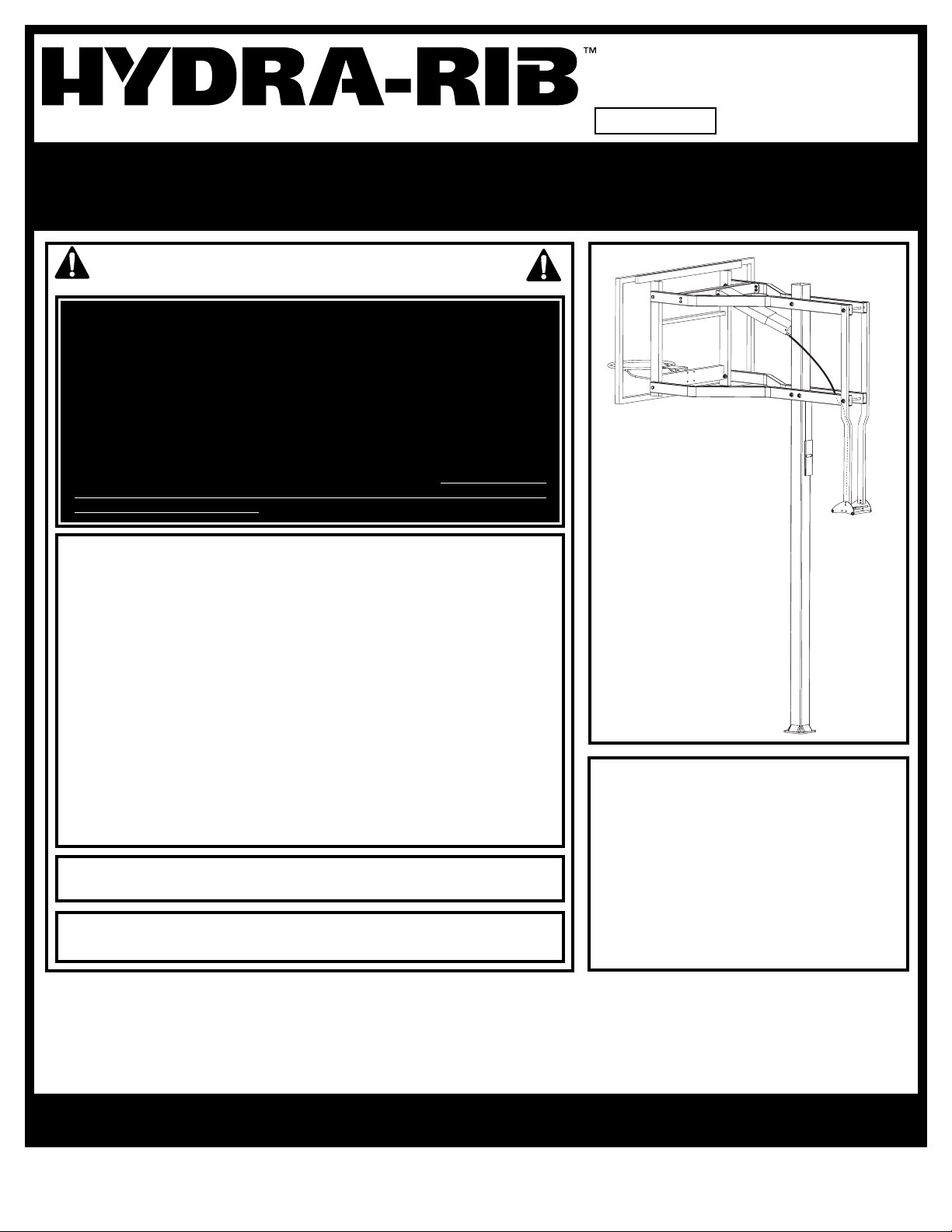
In-Ground Basketball System
Owners Manual
© COPYRIGHT 2002 by HUFFY SPORTS
A Huffy Sports Company
Customer Service Center
N53 W24700 South Corporate Circle
Sussex, WI 53089
U.S.A.
WRITE IN YOUR MODEL NUMBER:
SAFETY INSTRUCTIONS
Most injuries are caused by misuse and/or not following instructions.
Use caution when using this system.
• If using a ladder during assembly, use extreme caution.
• Two (2) people are reccomended for this operation.
• Seat the pole sections properly. Failure to do so could allow the pole sections to
separate during play.
• Before digging, contact utility company to locate underground power cables, gas,
and water lines. Ensure there are no overhead power lines within 20 ft. (7 m) radius
of pole location.
• Climate, corrosion, excessive use, or misuse could result in system failure.
• If technical assistance is required, contact Huffy Sports.
• Minimum operational height is 6'6" (1.98 m) to the bottom of backboard.
• This equipment is intended for home recreational use only and NOT excessive
competitive play.
• Read and understand the warning label affixed to pole. Label is shown on page 2.
• The life of your basketball pole depends on many conditions. The climate,
placement of the pole, the location of the pole, exposure to corrosives such as
pesticides, herbicides or salts are all important.
• Adult supervision is recommended when adjusting height.
• Serious injury could occur if teeth/face come in contact with backboard, net, or rim.
FAILURE TO FOLLOW THESE SAFETY INSTRUCTIONS MAY RESULT IN
SERIOUS INJURY, PROPERTY DAMAGE AND WILL VOID WARRANTY.
Owner must ensure that all players know and
follow these rules for safe operation of the system.
To ensure safety, do not attempt to assemble this system without following the
instructions carefully. Proper and complete assembly, use and supervision is
essential for proper operation and to reduce the risk of accident or injury. A
high probability of serious injury exists if this system is not installed,
maintained, and operated properly. Check entire box and inside all packing
material for parts and/or additional instructional material. Before beginning
assembly, read the instructions and identify parts using the hardware identifier
and parts list in this document.
For more information on assembly, placement, proper use and maintenance,
visit The American Basketball Council website at http://www.smarthoops.com.
Page 2
2
P/N 21166904 10/04
IMPORTANT! WRITE MODEL NUMBER FROM BOX ONTO PAGE 1 OF THIS OWNERS MANUAL
WARNING
F AILURE TO FOLLOW THESE WARNINGS MAY RESULT
IN SERIOUS INJURY AND/OR PROPERTY DAMAGE.
Owner must ensure that all players know and follow
these rules for safe operation of the system.
• See instruction manual for proper installation.
• DO NOT HANG on the rim or any part of the system
including backboard, support braces or net.
• During play, especially when performing dunk type
activities, keep player's face away from the backboard, rim
and net. Serious injury could occur if teeth/face come in
contact with backboard, rim or net.
• Do not slide, climb, shake or play on pole.
• When adjusting height, keep hands and fingers away from
moving parts.
• Do not allow children to move or adjust system.
• During play, do not wear je
welry (rings, watches,
necklaces, etc.); objects may entangle in net.
• Keep organic material away from pole base. Grass, litter,
etc. could cause corrosion and or deterioration.
• Chec
k pole system for signs of corrosion (rust, pitting,
chipping) and repaint with with exterior enamel paint. If
rust has penetrated through the steel anywhere, replace
the pole immediately.
• Check system before each use for proper ballast, loose
hardware, excessive wear and signs corrosion and repair
before using.
• Check system before eac
h use for instability.
• Never play on damaged equipment.
• Keep pole top covered with cap at all times.
201255 2/99
1-800-558-5234
37
Page 3
3
10/04 P/N 21166904
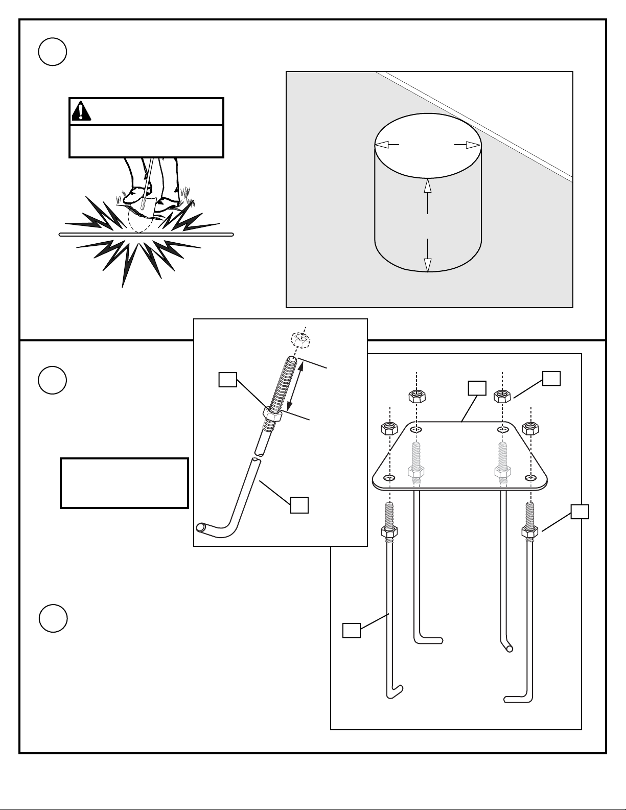
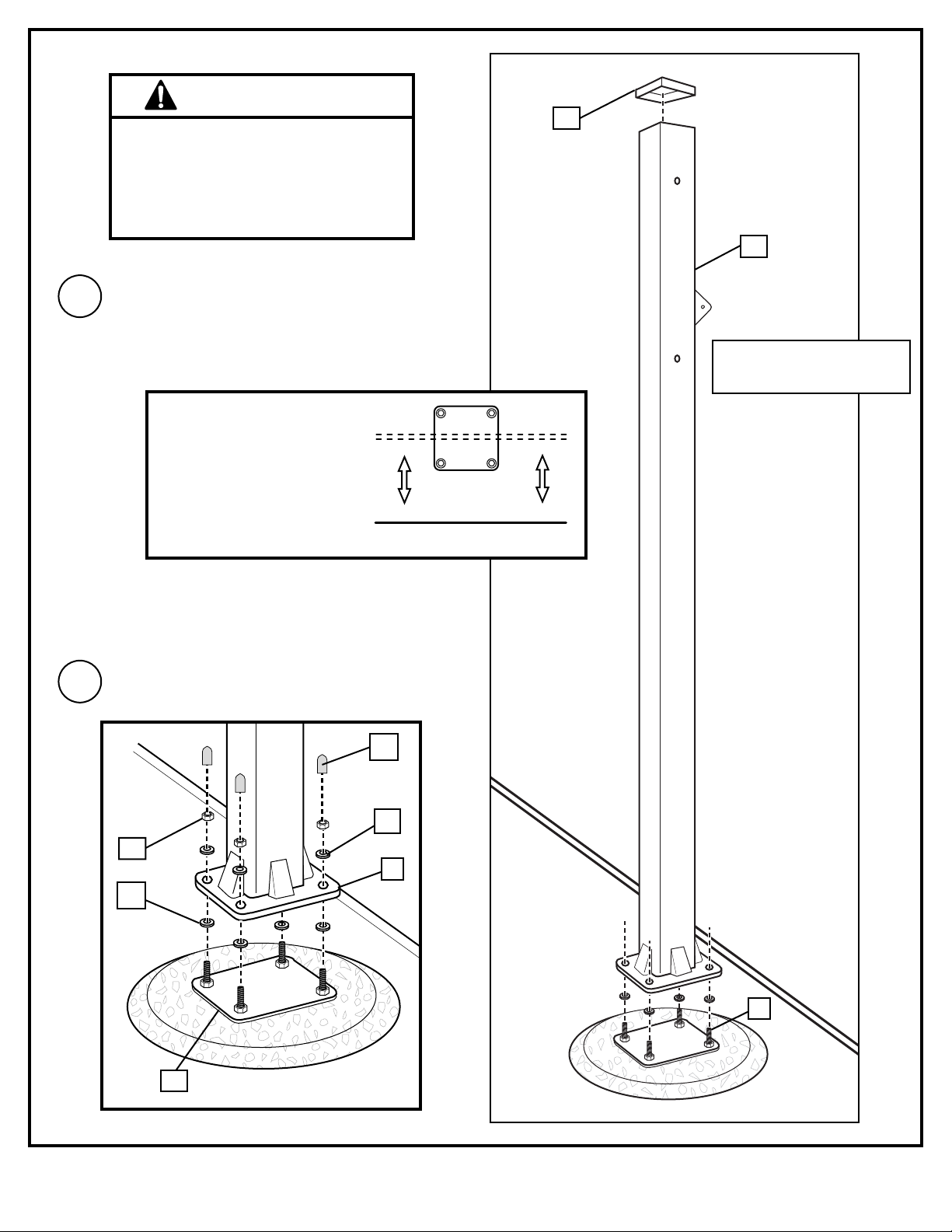
Ensure ground is level with playing
surface, then dig pole hole.
GROUND
SURFACE
PLAYING
SURFACE
1.
Install threaded ends of J-bolts (1) through holes in
mounting plate (3) and secure as shown.
NOTE: Make sure J-bolts (1) are in the illustrated
position.
NOTE: Nuts on the top of plate are used for leveling
the pole after system is fully assembled.
2.
3
2
2
2
1
3.
1
CONTACT UTILITIES
BEFORE DIGGING.
Install nut (2) to J-bolt (1)
as shown. Repeat
procedure for other three
J-bolts (1).
WARNING
2”
(5.08 cm)
IMPORTANT!
Make sure nuts are 2”
(5.08 cm) from top of J-Bolts.
24" (61 cm)
36" (91.4 cm)
Page 4
4
P/N 21166904 10/04
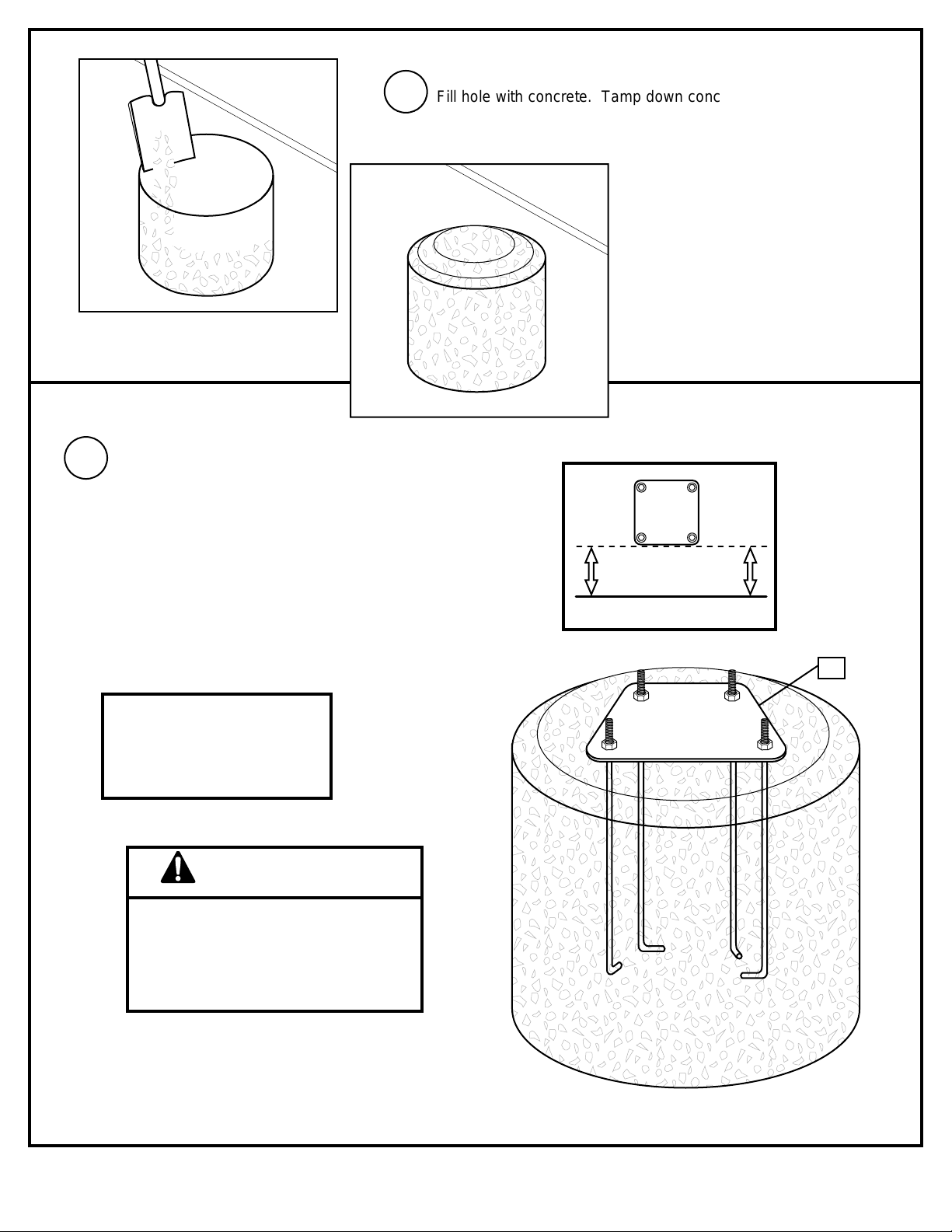
Fill hole with concrete. Tamp down concrete
to release air pockets and build drainage hill.
Insert J-bolts (1) from mounting plate (3) into
cement as shown. Move assembly around to
release any air pockets in cement, then rest
mounting plate on cement drainage hill. Apply
some pressure to level mounting plate on top of
drainage hill. Level mounting plate and square
with playing surface. Clean off any excess
cement on mounting plate at this time.
NOTE: Check leveling of mounting plate (3)
several times while concrete is curing.
4.
5.
IMPORTANT!
Front of mounting plate (3)
must be parallel with playing
surface.
DO NOT PROCEED TO STEP 6 UNTIL
CONCRETE HAS CURED FOR A
MINIMUM OF 72 HOURS. ALLOW
ADDITIONAL TIME FOR COLD, WET
OR HUMID WEATHER.
WARNING
PLAYING SURFACE
3
Page 5
5
10/04 P/N 21166904
Upright pole (5). Assemble lower pole flange
onto protruding J-bolts (1) as shown. The
flange will then rest on the nuts (2) from Step 2.
Secure pole (5) flange to mounting plate
(3) as shown. Tighten completely.
6.
7.
5
TWO PERSON MINIMUM REQUIRED
FOR THIS PROCEDURE. NOT
FOLLOWING RECOMMENDATION
MAY RESULT IN SERIOUS BODILY
INJURY AND/OR PROPERTY
DAMAGE.
WARNING
PLAYING SURFACE
PLAYING
SURFACE
IMPORTANT!
Holes in pole must be parallel
with playing surface.
14
38
3
7
6
14
5
1
NOTE: Orientation bracket
must face playing surface.
Page 6
6
P/N 21166904 10/04
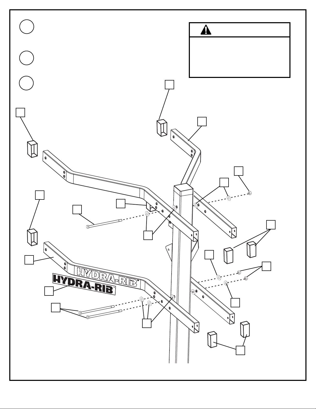
8.
Insert caps (8) into end of each support arm (9)
as shown. Tap firmly in position.
Apply logo label (11) to lower support arms (9) as
shown. Repeat for opposite side.
Beginning with upper support arms (9) secure
support arms to pole. Continue by securing lower
support arms (9) as shown.
9.
10.
TWO PERSON MINIMUM REQUIRED
FOR THIS PROCEDURE. NOT
FOLLOWING RECOMMENDATION
MAY RESULT IN SERIOUS BODILY
INJURY AND/OR PROPERTY
DAMAGE.
WARNING
7
8
8
8
8
8
8
14
4
9
11
9
12
12
7
4
4
4
Page 7
7
10/04 P/N 21166904
11.
16
4
13
9
4
7
4
9
7
4
9
7
4
16
4
7
4
9
16
4
16
TWO PERSON MINIMUM REQUIRED
FOR THIS PROCEDURE. NOT
FOLLOWING RECOMMENDATION
MAY RESULT IN SERIOUS BODILY
INJURY AND/OR PROPERTY
DAMAGE.
WARNING
IMPORTANT!
Do not over tighten.
Secure H-frame (13) to support arms (9).
Page 8
8
P/N 21166904 10/04
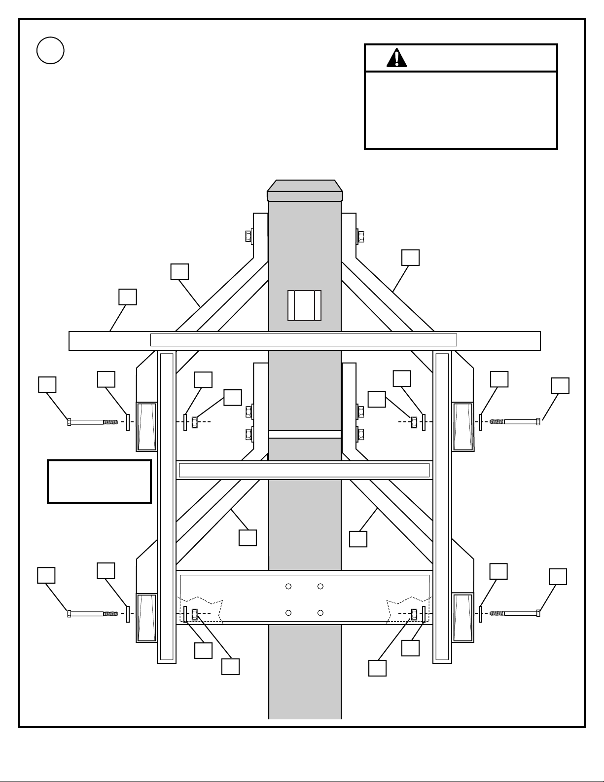
12.
Install cross brace (17) with nuts (59) and bolts
(22) as shown. Repeat for opposite side.
17
22
59
Page 9

9
10/04 P/N 21166904
53
4
4
13.
Install vertical supports (18), nuts (2), washers (4)
and bolts (53) as shown.
4
4
2
2
53
18
IMPORTANT!
The end with the double holes need
to be toward the playing surface
Page 10

10
P/N 21166904 10/04
14.
Attach handle plates (21) to vertical supports (18)
as shown. Attach cable bracket (20) to handle
plates (21) as shown.
54
23
23
5423
23
55
55
54
54
21
20
21
18
18
SIDE VIEW
Page 11

11
10/04 P/N 21166904
15.
Remove tie strap that secures cable to strut
assembly. Slide shroud (36, 46) over strut
assembly (35) as shown.
16.
Mount activator bracket (47) to strut assembly
(35) with hardware as shown.
35
46
47
56
63
36
35
35
46
CAUTION!
Do not depress valve stems.
Pressing strut valve stems will
cause a rapid extension of the
strut and possible injury.
CAUTION!
Do not depress valve stems.
Pressing strut valve stems will
cause a rapid extension of the
strut and possible injury.
NOTE:
DO NOT OVERTIGHTEN
NUT (52) ONTO BOLT (56).
BRACKET (47) SHOULD
MOVE FREELY.
Page 12

12
P/N 21166904 10/04
17.
Attach strut/shroud assembly to crossbrace (17)
and pole as shown.
7
65
59
61
17
Page 13

13
10/04 P/N 21166904
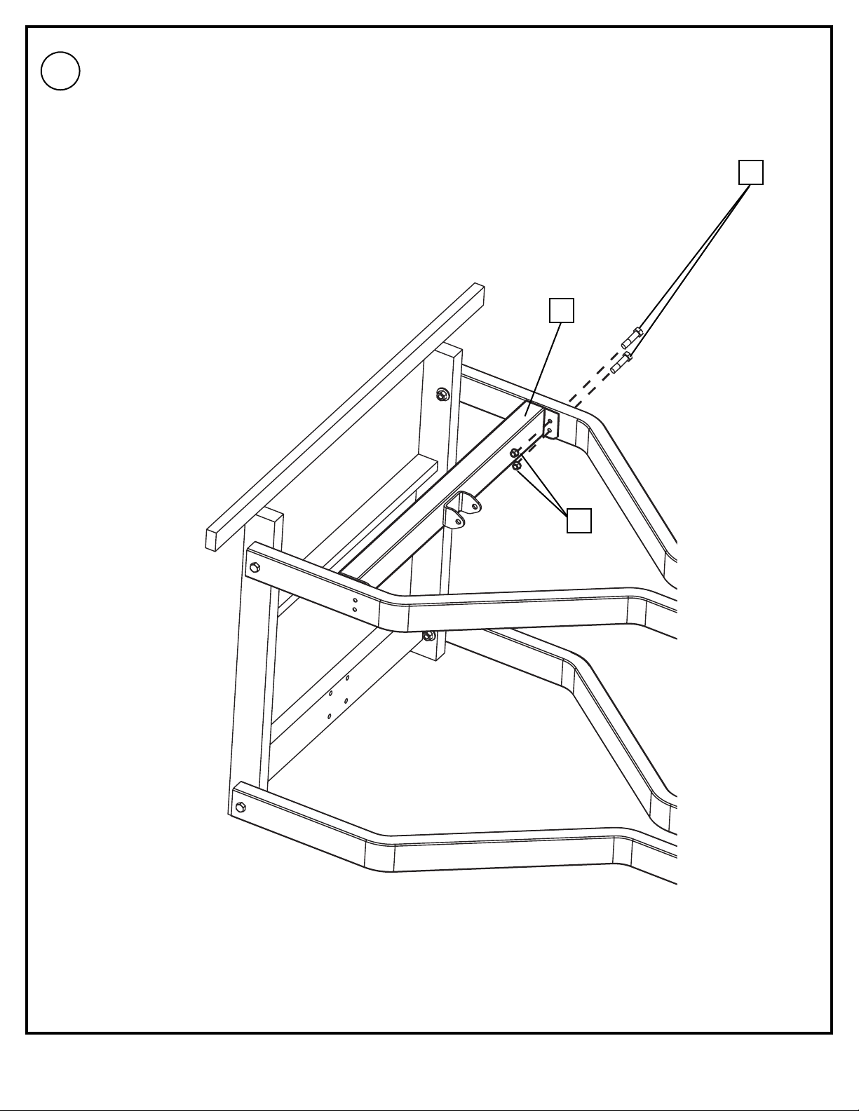
18.
Run the cable from strut assembly around the pole,
through the hole in the vertical support (18) and down
through the hole in the cable bracket as shown (20).
Place one nut on top of the cable bracket and one
below as illustrated. Tighten the bottom nut until 1/8”
of thread is exposed as illustrated.
Opposite Side View
20
18
Page 14

14
P/N 21166904 10/04
Begin trigger assembly by pulling wire through slot on trigger(48) as shown.
Complete this assembly by installing trigger to plates with bolt (53) and bolt (58).
Carefully attach cable end to actuator plate (47).
7
42
52
58
66
19 A.
19 B.
48
47
NOTE:
DO NOT OVERTIGHTEN
NUT (42) ONTO BOLT (58).
TRIGGER (48) SHOULD
MOVE FREELY.
Page 15

15
10/04 P/N 21166904
20.
Slide shroud over strut assembly and attach shroud
with screw (60) as shown.
60
Page 16

16
P/N 21166904 10/04
RIM ASSEMBLY & INST ALLATION
WARNING
21.
Install carriage bolt (41) through rim (25),
washers (4) and (27) as shown. Tighten
nut (43) completely. Place nut (42) about
half-way up carriage bolt (41) as shown.
25
4
41
27
43
TWO PERSON MINIMUM REQUIRED FOR THIS
PROCEDURE. NOT FOLLOWING RECOMMENDATION
MAY RESULT IN SERIOUS BODILY INJURY AND/OR
PROPERTY DAMAGE.
Attach foam pad (19) to Backboard. Attach bracket
(39) to backboard and support structure by inserting
bolts (26) and washers (24) through top holes in
bracket (39), Tighten nuts (23) completely.
26
39
24
23
24
22.
23
24
24
40
26
Insert inner bracket (40) into bracket (39) as shown.
Insert bolts (26) and washers (24) through top holes
of inner bracket (40) as shown.
Now tighten backboard/frame nuts (23) completely.
23.
39
40
39
42
41
27
19
Page 17

17
10/04 P/N 21166904
24.
25
39
40
Insert spacer (45) through rim assembly (25). Place rim assembly on bracket (39) so that carriage bolt (41) is
inserted through hole on top of inner bracket (40). Install hex bolt (44), washers (27) and nut (42) through top
holes on bracket (39) through spacer (45) as shown.Tighten completely.
Install spring (28), concave washer (29) and
center lock nut (30) to carriage bolt (41) as
shown.
28
41
30
29
BOTTOM VIEW
45
25
41
Do not over tighten as rim will not flex
properly. See leveling instructions to
determine how much to tighten nuts
(42) and (30).
25.
44
27
27
45
42
NOTE
27
Page 18

18
P/N 21166904 10/04
26.
27.
28.
Apply logo label (33) to cover plate (31). Install
cover plate (31) on rim (25) using self tapping
screws (32) as shown.
LEVELING INSTRUCTIONS:
Place level on rim (25) and adjust nut (42) until
level. Tighten nut (30) to set rim tension for
playing.
Secure net (34) to
rim (25).
1
2
3
34
25
NOTE ORIENTATION OF COVER PLATE
OUTSIDE VIEW
4
32
31
33
42
25
30
10 feet
(3.05 m)
NOTE: Official rim height is
10’(3.05 m) from top of rim
to playing surface.
Page 19

19
10/04 P/N 21166904
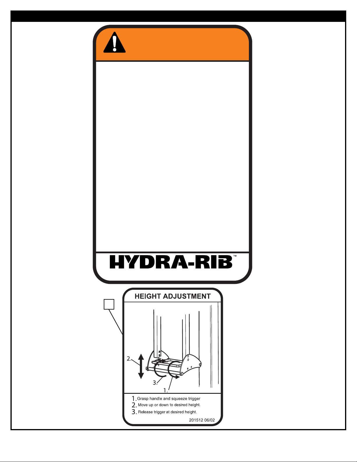
Apply height adjustment
label (37) to front of pole
as shown.
30.
10 feet
(3.05 m)
REGULATION
RIM HEIGHT IS
10 FEET (3.05 m).
37
29.
Check leveling at this time. Pole should
be level in all directions. NOTE: If
adjustment is necessary, adjust system by
rotating the nuts (2) between mounting
plate (3) and pole flange. (Referred to in
Step 6.) After system is leveled,
completely tighten nuts (7) above pole
flange.
Page 20

20
P/N 21166904 10/04
31.
Attach hook (49) to height strip (50) as shown.
Attach this assembly to unit with bolt (12) and nut (7)
as shown.
49
50
12
15
63
62
Page 21

21
10/04 P/N 21166904
51
51
57
32.
Attach height window (51) to pole using four
pieces of double-sided tape (57) as shown.
50
11
1/2”
Secure pole pad (35) as
shown.
33.
64
Page 22

22
P/N 21166904 10/04
To install height marking labels (10), raise backboard so
that the rim is 10’ off the playing surface (two people
required for this procedure). Remove 10’ mark label from
sheet and insert label on (50) through window of (51).
Repeat for all other height markings.
10
Page 23

23
10/04 P/N 21166904
Valve
Valve
Trigger released,
locking elevator
Trigger squeezed,
unlocking elevator
If the elevator is still difficult
to operate, verify that the
valves located on the strut
are fully depressed when the
trigger is activated.
NOTE: two people are
required for this procedure.
Adjust exposed cable length,
located next to the trigger
(See Step 19) by using the
jam hex nuts on the cable
end. Slide outer shroud to
exposed valves. The valves
must be fully depressed so
elevator can be adjusted
smoothly and fully extended
to lock the elevator.
Jam Hex Nuts
Page 24

24
P/N 21166904 10/04
Item Qty.
Part No. Description
1 4 200573 J-Bolt, 1/2”-13 x 24”
2 12 265575 Nut, Hex 1/2”-13
3 1 920880 Mounting Plate
4 23* 203474 Washer, Flat 1/2” x 1” O.D.
5 1 980835 Pole
6 1 200544 Pole Cap, Square
7 12 206340 Nylon Insert Lock Nut, Hex 1/2”-13
8 8 220589 Cap, Arm Support Insert
9 4 908066 Support Arm
10 1 201504 Label, Height Marker
11 2 220586 Logo Label, 15” x 1 3/4”
12 4 200574 Bolt, Hex Flange 1/2”-13 x 9”
13 1 906835 H-Frame
14 8 200704 Washer, 5/8”
15 2 202459 Nut, Hex, 1/2”
16 4 202856 Bolt, Hex Head,1/2”-13 x 4”
17 1 908061 Crossmember
18 2 908062 Vertical Tube
19 1 203274 5 x 5 Foam Pad
20 1 901492 Cable Support Bracket
21 2 901490 Plate Handle
22 4 203113 Bolt, Hex Flange 5/16”-18 x 2 1/2”
23 12* 203100 Nut, Hex Flange 5/16”-18
24 12 203218 Washer, Flat 5/16” x 7/8” O.D.
25 1 920263 Rim, Orange
26 4 201611 Bolt, Hex Flange, 5/16”-18 x 3”
27 12* 203232 Washer, 3/4 O.D.
28 1 200484 Spring
29 1 200323 Washer, Large Flat
30 1 201124 Nut, Hex Locking, 3/8-16
31 1 960043 Cover Plate, Orange
32 2 220140 Screw, Self Tapping, 1/4 - 20 x 1/2
33 1 220569 Label Logo Circle
34 1 204282 Net
35 1 900429 Strut Assembly
36 1 201982 Outer Shroud
37 1 201512 Label, Height Adjustment
38 4 200655 Bolt Covers
39 1 920262 Bracket, Orange
40 1 920038 Inner Bracket, Black
41 1 220065 Bolt, Carriage 3/8 x 5 1/2
42 2 203063 Nut, Hex Nylon Locking 3/8
43 1 203017 Nut, Hex 3/8
44 1 203439 Bolt, Hex 3/8 x 6
45 1 220064 Spacer, 5 x 1/2” O.D.
46 1 201983 Inner Shroud
47 1 908064 Actuator Plate
48 1 901493 Trigger Assembly
49 1 201501 Shepherd’s Hook
50 1 201503 Height Strip
51 1 201502 Height Window
52 1 201511 Handle Spacer
53 2 201981 Bolt 1/2-13 x 12”
54 4 203217 Bolt 5/16 x 1 1/2
55 2 201531 Bolt 5/16 x 3/4
56 1 203078 Bolt 1/4-20 x 4”
57 4 207388 Double Sided Tape
58 1 201515 Bolt 3/8 16 x 11
59 5 203220 Locknut, 5/16-18, Nylon
60 1 201519 Screw 6 x 1 Slotted Hex Head
61 1 203664 Bolt Hex Head 5/16-18 x 5-1/2” Long
62 2 240019 Bolt Hex Head 1/4-20 x 3/4 Long
63 3 240027 Nut Hex Nylock 1/4-20
64 1 206555 Pole Pad
65 1 206251 Bolt, Hex, 1/2” x 5” Long
66 1 201506 Bolt, Hex, 1/2” x 11” Long
* You May Have Extra Parts With This Model.
PARTS LIST
Item #16 (4)
Item #22 (8)
Item #26 (4)
Item #2 (12)
HARDWARE IDENTIFIER
Item #4 (23)*
Item #7 (12)
Item #23 (14)
Item #24 (12)
Page 25

25
10/04 P/N 21166904
Item #41 (1)
Item #30 (1)
Item #32 (2)
Item #42 (2)
HARDWARE IDENTIFIER
Item #44 (1)
Item #45 (1)
Item #43 (1)
WARRANTY CARD:
Please remember to complete your product
registration form on-line at:
www.hydrarib.com/warrantycard
Item #27 (12)*
Item #29 (1)
Item #38 (4)
Item #54 (4)
Item #55 (2)
Item #56 (1)
Item #59 (5)
Item #60 (1)
Item #61 (1)
Item #62 (2)
Item #63 (3)
 Loading...