

S&P TR90 Series, TR90G, TR90, TR130, TR200 Installation And Operation Manual
...
S&P
USA: Tel (800) 961-7370, Fax (800) 961-7379, www.solerpalau-usa.com
Canada: Tel (866) 733-0233, Fax (866) 358-5346, www.solerpalaucanada.com
Mexico: Tel 52 (222) 2 233 900, Fax 52 (222) 223 3914, www.soler-palau.com.mx
INSTALLATION AND OPERATION MANUAL
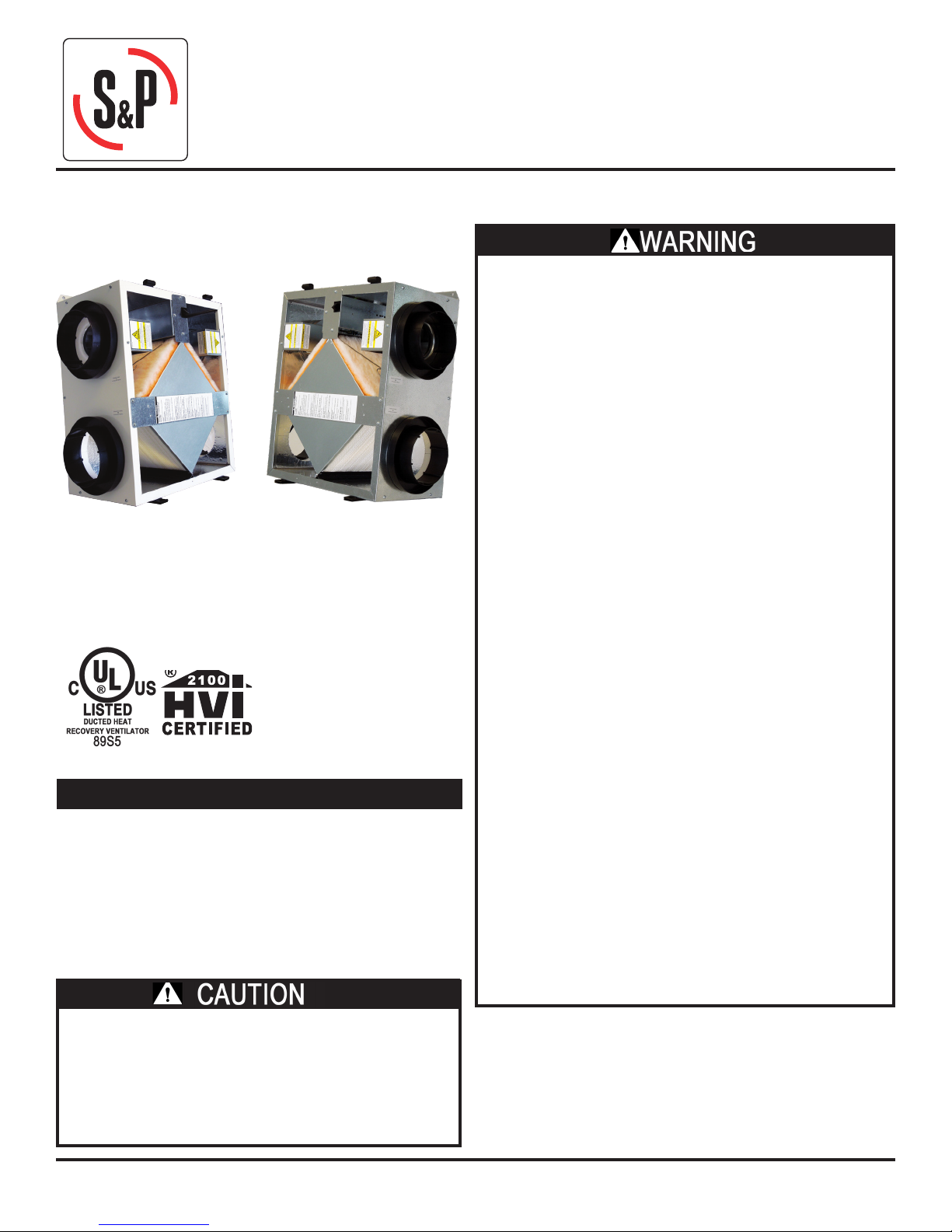
90-Series
TR90:
Painted Case
Low Voltage Controls
Line Cord
Before You Begin
Read all instructions before installing the unit. Also review
supplemental instructions included with any controls that
will be installed. Carefully unpack and inspect the unit
for shipping damage. Open the access door and inspect
inside the unit. Attach the four duct collars to the unit
with the screws provided in the plastic small-parts bag.
TR90G:
Galvanized Case
Line Voltage
No Line Cord
RISK OF FIRE, ELECTRIC SHOCK, OR INJURY.
OBSERVE ALL CODES AND THE FOLLOWING:
1. Before servicing or cleaning the unit, unplug the unit line
cord or shut o power at service switch or circuit breaker.
Make sure unit is not running before opening its door.
2. This installation manual shows the suggested
installation method. Additional measures may be
required by local codes and standards.
3. Installation work and electrical wiring must be done
by qualied professional(s) in accordance with all
applicable codes, standards and licensing requirements.
4. Any structural alterations necessary for installation
must comply with all applicable building, health, and
safety code requirements.
5. Connect this unit only to a 120VAC grounded circuit
protected by a 15 amp circuit breaker.
6. Do not install unit or controls where they can be
reached from a tub or shower.
7. This unit must be properly ducted to the outdoors.
8. Outside air inlet for this unit must be located away
from sources of hazardous air such as auto exhausts.
9. Sucient air is needed for proper combustion and
exhausting of gases through the ue (chimney) of fuel
burning equipment that might be installed in the area
aected by this equipment. If this unit is exhausting
air from a space in which chimney-vented fuel burning
equipment is located, take steps to assure that combustion
air supply is not aected. Follow the heating equipment
manufacturer’s requirements and the combustion air
supply requirements of applicable codes and standards.
10. This unit is intended for general ventilating only. Do
not use to exhaust hazardous or explosive materials
and vapors. Do not connect this unit to range hoods,
fume hoods or collection systems for toxics.
11. When cutting or drilling into wall or ceiling, do not
damage electrical wiring and other hidden utilities.
12. Use the unit only in the manner intended by the manufacturer.
If you have questions, contact the manufacturer.
1. To avoid motor bearing damage and noisy and/
or unbalanced impellers, keep drywall spray,
construction dust, etc., out of the unit.
2. Do not connect power to the units external control
terminals: this will damage the unit. The external
terminals are for use only with un-powered controls
designed for low-voltage operation.
TR90-Series Due to continuing product development, specications are subject to change without notice. © 2018 S&P
132104_002 Revised 8/2018 Page 1

Location of the Unit
Inside Ductwork System
Select a location so that:
• The fresh air intake vent from the outside is placed a
minimum of ten feet from any other exhaust vent, and is at
least 30” long.
• The two ducts to the outside are as short and straight as
possible for the best performance from the system. Shorter
duct runs help assure the system is balanced: the amount of
air brought in is equal to the amount of air exhausted.
• The door can be opened to allow cleaning the core and
lters. Provide clearance at front of unit for service
access to the blowers, lters and energy exchange core.
(24” recommended/12” minimum.)
• The exhaust outlet and fresh air inlet on the outside of the
building should be at least ten feet apart to avoid crosscontamination. The exhaust duct should be about the same
length as the fresh air duct.
• The exhaust outlet should not dump air into an enclosed
space or into any other structure.
• Do not install the exhaust outlet and fresh air inlet through
the roof or roof sot. If these are the only available options
call S&P technical support for help.
The preferred mounting location for the unit is on a concrete
foundation wall because the foundation wall isolates any blower
vibration.
If a basement area is not available or practical, use other
mechanical room space such as a closet, garage, storage, or
accessible attic or crawl space.
NOTE: If you wish to install the unit in an attic or other
unconditioned space, you must insulate all of the unit’s ductwork
that is located in the attic. Use at least R-6 insulation.
RA: Room Air
OA: Outside Air
FA: Fresh Air
EA: Exhaust Air
SA: Supply Air (furnace)
For houses without ducted heating or cooling systems – see
Schematic (B):
In most houses one or two fresh air grilles in a central part of
the house provide eective distribution of the fresh air into the
home, particularly when the stale exhaust air is picked up at
several points. Because the fresh air is usually somewhat cooler
than the household air, the fresh air supply grilles should be
located in a trac area like a hallway or stairway rather than in
a sitting area. If you want to get fresh air into specic rooms with
high occupancy, you can split up the fresh air supply.
For houses with forced-air heating and cooling systems – see
Schematics (A), (C) and (D):
Most units are installed with the fresh air duct connected directly
to a return duct for the main heating and cooling system. Be
careful to connect the fresh air duct at least three feet from the
return plenum to minimize suction from the furnace blower. A
connection closer to the furnace may result in unbalanced ow
and associated problems.
For installations that collect stale air from specic rooms in
the home – for example, Schematics (A) and (B):
Locate stale air return grilles (RA) in rooms where moisture and
odors are generated: bathrooms, the kitchen, and perhaps other
areas where contaminants are generated such as in the home
workshop. Return grilles in these other areas may be dampered
so that they can be shut o when not in use. A central location
such as a hallway is also acceptable but won’t clear humidity and
odors from baths and kitchens as rapidly. Locate stale air return
grilles (RA) near the ceiling on inside walls. Stale air returns are
usually easiest to install in interior partitions.
Stale Air Return Grille Sizes
Bathroom 4” X 10” or 6” X 10” - 40 to 60 sq. in.
Kitchen 6” X 10” or 60 sq. in.
Separate Room Air Pick-up -
(A) (B)
Fresh Air to Furnace Return Air Trunkline
Furnace Return Air Back into Return Air
(C) (D)
Separate Return Air and Fresh Air Supply
Furnace Return Air Back into Supply Air
*TR90 only
TR90-Series Due to continuing product development, specications are subject to change without notice. © 2018 S&P
132104_002 Revised 9/2018 Page 2
Exhaust & Outside Air Ducts
Mounting the Unit
The Exhaust Air Duct and the Outside Air Duct connect the unit to
the outside. Flexible insulated duct is typically used. See Table
under “Duct Sizes” below.
DO NOT PLACE ANY STALE AIR RETURNS IN GARAGES.
Can an ERV be used to ventilate bathrooms?
A S&P ERV can be used as a central exhaust system in place of
bathroom exhaust fans. Tie a grill in each bathroom directly
back to the ERV – see Schematic (A). A successful installation
should provide at least 50 CFM of exhaust per moisture producing
bathroom. When used for bathroom exhaust, the TR90 should
be used for only one bathroom. Install a control in the bathroom
ventilated by the ERV (see Secondary Operating Controls, below).
For houses where radon is a concern:
The rst line of defense against radon should always be techniques
that prevent the entry of radon into the home, such as under-slab
suction, vented perimeter drainage, and crack sealing. However,
if moderate levels of radon continue to be present, it is important
that the unit slightly pressurize the basement, not de-pressurize
the basement.
Installation of this unit for radon mitigation is beyond the
scope of this manual. Consult a radon mitigation professional.
Duct Sizes
Duct Minimum Sizes and Type
Exhaust Air & Outside Air
(EA & OA)
Fresh Air & Stale Air
(FA & RA)
All ducts from unit to house in unconditioned spaces like
attics and crawl spaces MUST BE INSULATED.
6” round insulated duct
8” round insulated duct may be
used to maintain maximum airow
6” round or 8” oval rigid
un-insulated
Unit may be installed in any orientation:
Orient the unit for the simplest duct layout and connections.
Note however that the door is equipped with slide-o hinges. For
the homeowner’s convenience it is helpful to orient the unit so
that the door does not drop o when it is unlatched.
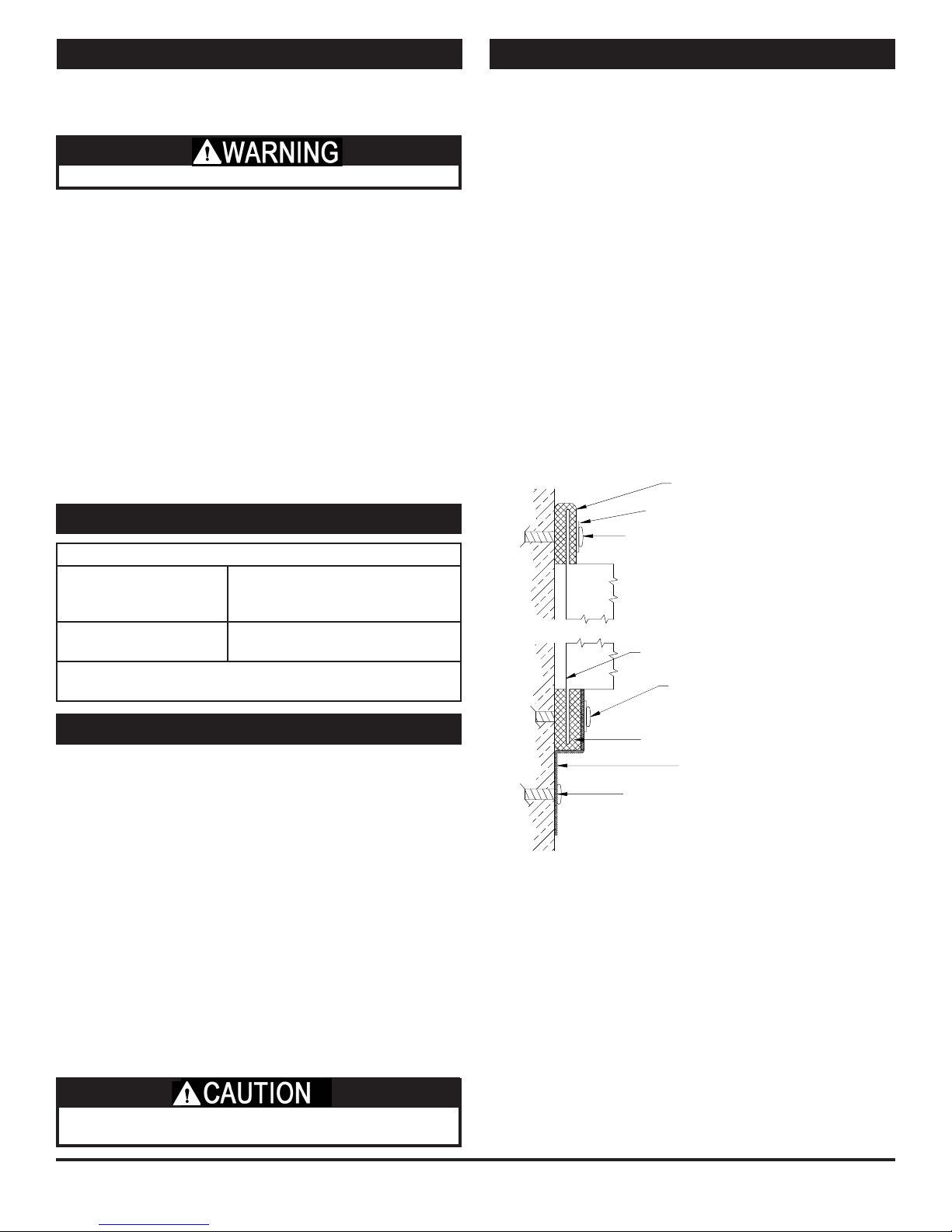
Mounting the TR90 on a concrete foundation wall:
Mount hanging bracket to the wall with appropriate concrete
anchors. Use pre-cut foam tape from small parts bag. Remove
backing and apply two pieces of foam tape equally spaced along
the unit’s mounting ange to be held by the hanging bracket. Apply
the other two pieces of foam over two holes that will be used for
fastening, on the other ange. The tape should be applied in a “U”
shape to cushion both the front and back of the integral anges.
Lift unit and slide unit ange into the hanging bracket. Using metal
at washers, fasten ange opposite hanging bracket to structure.
Safety screws should similarly be installed passing through the
hanging bracket and ange. Make sure the screws, which you must
supply, are properly selected for the loads and substrate involved.
Mounting the TR90 to a stud wall:
Mount unit using supplied hanging bracket kit as described for
mounting to concrete foundation wall. Note that the hole layout
on the integral mounting anges and the hanging bracket are
spaced for 16” on-center framing patterns.
Foam Tape
Metal Washer
Lag Screw or Concrete Anchor
(provided by others)
Unit Flange
Optional Washer and Screw
(provided by others)
Controls
For an installation in which the ERV should run continuously in
order to provide the required ventilation rate for the home,
no controls are needed. However, in most installations, control
over the unit operation is desired and this is best provided by a
Proportional Timer.
Proportional timers (SPTL or SFM controls for TR90 or line voltage
controls for TR90G) may be located anywhere that is convenient.
A typical location for either control is next to the home’s
thermostat. Proportional timers operate the ERV to provide
regular background ventilation of the home.
TR90 installations that pull stale air from specic rooms, such as
bathrooms, should have Push-Button Lighted (SPBL) Controls in
those rooms. The secondary operating controls allow the system
to be turned on from various locations in the house.
RISK OF INJURY WHEN LIFTING UNIT AND INSTALLING UNIT
OVERHEAD. GET A HELPER AND WEAR EYE PROTECTION.
TR90-Series Due to continuing product development, specications are subject to change without notice. © 2018 S&P
132104_002 Revised 8/2018 Page 3
Suspending the TR90 from oor joists or trusses:
The unit may be screwed directly to joists or trusses using the
hanging bracket and integral ange. Mount as described for
mounting to concrete foundation wall. Note that the hole layout
on the hanging bracket is spaced for 16”on-center layouts.
Mounting the TR90G:
The TR90G can be mounted similar to the TR90 however, the
TR90G does not come with a hanging bracket. Using at washers
provided install screws through the holes in the anges of the
unit. Make sure the screws, which you must supply, are properly
selected for the loads and substrate involved.
Foam Tape
Hanging Bracket
Lag Screw or Concrete Anchor
(provided by others)
* TR90 only.
Installing Outside Air & Exhaust Air Ducts
Electrical Connections
Ducts connecting the unit to the outside must be well- insulated.
Vapor barrier is required on both inside and outside of the insulation.
Band or tape inner duct liner to inner ange of appropriate collar.
Drive a sheet metal screw through liner to secure duct spiral wire
to collar. Straighten insulation, and slide outer duct jacket onto
the outer ange of the duct collar. Secure with band or tape.
The vapor barrier should be continuous and sealed against air
and moisture leakage! If not, condensation or ice may form
in cold weather on the duct surface or in its insulation!
The inlets and outlets should be screened against insects and vermin
and shielded from the weather to prevent the entry of rain or snow.
INSTALL FRESH AIR INLET AWAY FROM SOURCES OF CONTAMINANTS.
• Do not locate the fresh air inlet where vehicles may be
serviced or left idling.
• The fresh air inlet should be at least ten feet away from
any exhaust such as dryer vents, chimneys, furnace, and
water heater exhausts or other sources of contamination
or carbon monoxide.
• Never locate the fresh air inlet inside a structure.
Installing Return Air (RA) Ducts
All the stale air returns are connected by ducts to the unit.
Generally, empty stud cavities are used for returns as is often
done with cold air returns for the furnace, using standard duct
boots to connect to six inch pipe at the bottom or top of the
wall cavity. Always be sure to seal all joints with duct sealant
or tape. Some local codes may require metal ducting all the way
from the boots to the stale air grilles. Use rigid ducts to allow the
air to move freely and easily through the ducts. See chart under
System Layout to size your ductwork:
If duct runs are very long (over 30 feet of ex duct for 90 CFM) or
have excessive bends or elbows or if maximum air ow rates are
required, eight inch insulated exible duct should be used. The
outer ange of the duct collar can be used for both the inner and
outer jacket of the exible duct. Care must be taken to insure
that the duct is securely fastened and sealed to the duct collar.
Do not use more ex duct than necessary!
Flex duct is much more resistant to airow than rigid duct; longer
runs of ex duct will reduce the ventilation performance of your
system. Stretch ex duct and avoid sharp bends.
NOTE: DISCONNECTION MEANS. Most electrical codes require
that the unit be disconnected for service. Depending on local
codes, an electrical outlet (for TR90) or an on/o switch
available for the unit (TR90G) may satisfy this requirement.
Power supply connection to TR90G is made in its electrical box
through the hole in the end pan. Pull out the unit electrical box
and connect the power wire conductors to the terminal block
inside the electrical box. The terminal block inside the electrical
box is conveniently marked for connection of eld power wiring.
After connecting the power wire conductors to the terminal
block re-install the electrical box in the unit.
S&P oers the TR90 with a line cord for connection to an
electrical outlet. If a TR90 with a line cord is installed and the
installer desires to convert to eld power wiring, should local
codes permit, simply remove the line cord from the terminal
block and connect eld wiring as described above.
Installing Controls
The TR90 is oered with a control board for connection to external
controls. The TR90G runs continuously whenever power is supplied to it.
Optional Controls:
S&P oers a variety of controls specically designed to work with
the TR90. These include: SPTL (a two wire proportional timer),
SFM (a six wire proportional timer that interconnects to the
furnace blower), and SPBL (point of use push button control).
Other controls that throw an unpowered switch may also be
used. The TR90G is a line voltage unit that may be controlled
with any line voltage control switch.
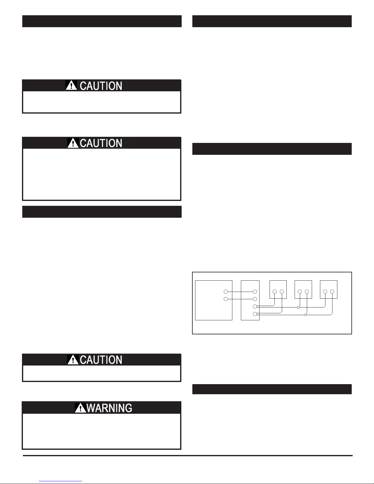
Typical Control Schematic:
Various wiring designs can be used to properly control the unit
and meet safety and code concerns. Consult your electrician for
an electrical design to meet your needs. The schematic below
shows a typical control system: a SPTL proportional timer plus
two SPBL push-button controls.
Up to (6) SPBL Controls, wired in parallel, may be used.
TR
* TR90 only.
(Not TR90G)
See installation manuals for the control(s) you select for wiring
diagrams and specic instructions.
SPTL
R
C
PB
PB
Only (2) SPBL Controls can be directly connected to the SPTL Control.
Wire any additional SPBLs in parallel with the first two.
SPBL
1
SPBL
2
SPBL
3
• Do not connect Dryers directly to the unit.
• Do not connect Range Hoods to the unit.
NOTE: Seal all duct collars at unit to minimize air leakage.
DANGER OF ELECTRICAL SHOCK WHEN SERVICING AN
INSTALLED UNIT.
ALWAYS UNPLUG UNIT BEFORE CONNECTING OR
SERVICING CONTROLS.
TR90-Series Due to continuing product development, specications are subject to change without notice. © 2018 S&P
132104_002 Revised 9/2018 Page 4
If NOT connecting controls to the TR90:
Make a jumper out of a short piece of wire. Connect the jumper
wire to the screw connections of the terminal strip on the outside
of the unit. ERV runs full-time once its power cord is plugged in.
Starting Up the Unit
• Inspect your installation to be sure all duct work is correctly
installed and sealed, that lters are in place, and controls
(if any) are connected.
• Shut and latch the door to the unit.
• Provide 120 VAC power to the unit. It may start immediately.
• Use control, if any, to turn on the unit. Check operation of
the control(s).
• Check that the unit’s safety interlock switch turns o the
unit when the door is opened.
Verifying Unit Performance
Airow
Airow should be occurring in both airstreams. Sometimes the
easiest place to conrm that air is moving is at the external
wall caps.
If exact airow is critical, it may be desireable to permanently
install ow measuring stations and manometers. These can
also be used to determine when lters should be cleaned or
changed.
Use Static Taps to Measure Airow Rates
See “Cross Core Static Drop” in MEASURING AIRFLOW table on
Page 6.
Use Damper to Balance Air Flow to Desired Rates, If
Necessary
The ERV’s blower motor are well suited for volume control by
dampers on the inlet of the units. One balancing damper is
provided in the units parts tray. NOTE: The unit is considered
balanced if the dierence between the two airows is not more
than 10 CFM.
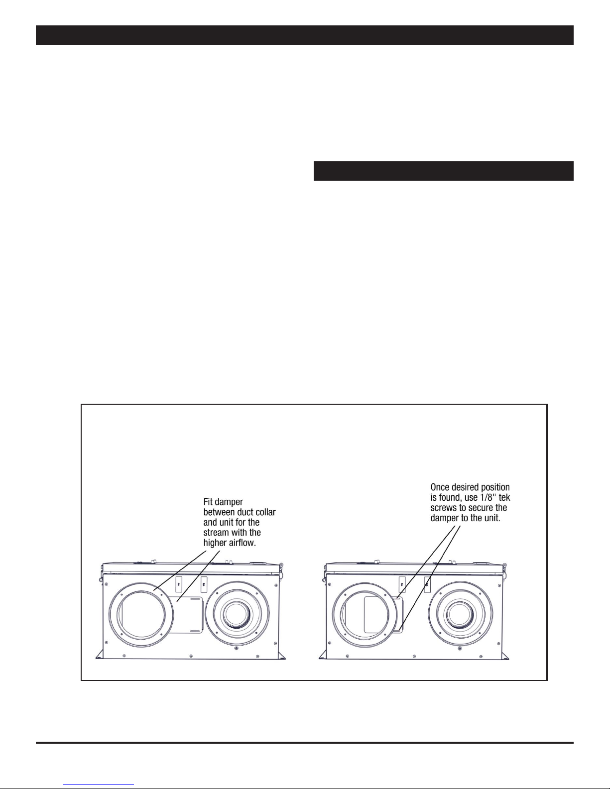
After measuring the airow of the units, the balancing damper
may be used to blance airow if desired. Place the damper
between the duct collar and the unit for the outlet of the
airstream recording higher ow. NOTE: Install the damper so
that it slides in the space between the duct collars for the TR90
and the TR90G.
Slowly move the damper further into the duct until the desired
airow is recorded. Secure the damper in place using 1/8” tek
screws (provided). NOTE: Drilling through the case while the
unit is running may cause metal shards to be drawn into the
unit.
Measuring Airow
Equipment Required
• A magnahelic gauge or other device capable of measuring 0
to 1.0 in. water of dierential pressure.
• 2 pieces of natural rubber latex tubing, 1/8” ID, 1/16” wall
works the best.
NOTE: be sure to remove cap from pressure port before
inserting tubing. Ensure tubing is well seated in pressure ports.
NOTE: The tubing should extend into the pressure port
approximately 1 inch.
Damper Installation
TR90-Series Due to continuing product development, specications are subject to change without notice. © 2018 S&P
132104_002 Revised 8/2018 Page 5
 Loading...