

Page 1

SOYO LI-7000
LPX SYSTEM
****************************************************
Socket 370 Celeron Processor supported
FW82810 AGP/PCI/AMR Chipset
66/100 MHz Front Side Bus supported
Custom LPX Form Factor
****************************************************
User's Manual
Page 2

SOYO™ LI-7000
FC
Copyright © 1999 by Soyo Computer Inc.
Trademarks:
Soyo is the registered trademark of Soyo Computer Inc. All trademarks are the
properties of their owners.
Product Rights:
All names of the product and corporate mentioned in this publication are used for
identification purposes only. The registered trademarks and copyrights belong to
their respective companies.
Copyright Notice:
All rights reserved. This manual has been copyrighted by Soyo Computer Inc. No
part of this manual may be reproduced, transmitted, transcribed, translated into any
other language, or stored in a retrieval system, in any form or by any means, such
as by electronic, mechanical, magnetic, optical, chemical, manual or otherwise,
without permission in writing from Soyo Computer Inc.
Disclaimer:
Soyo Computer Inc. makes no representations or warranties regarding the contents
of this manual. We reserve the right to amend the manual or revise the
specifications of the product described in it from time to time without obligation to
notify any person of such revision or amend. The information contained in this
manual is provided to our customers for general use. Customers should be aware
that the personal computer field is subject to many patents. All of our customers
should ensure that their use of our products does not infringe upon any patents. It is
the policy of Soyo Computer Inc. to respect the valid patent rights of third parties
and not to infringe upon or to cause others to infringe upon such rights.
Restricted Rights Legend:
Use, duplication, or disclosure by the Government is subject to restrictions set
forth in subparagraph (c)(1)(ii) of the Rights in Technical Data and Computer
Software clause at 252.277-7013.
About This Guide:
This Quick Start Guide can help system manufacturers and end users in setting up
and installing the Motherboard. Information in this guide has been carefully
checked for reliability; however, to the correctness of the contents there is no
guarantee given. The information in this document is subject to amend without
notice.
For further information, please visit our Web Site on the Internet. The address is
"http://www.soyo.com.tw".
Edition: August 1999
Version 1.0
LI-7000 SERIAL
Tested To Comply
C
With FCC Standards
FOR HOME OR OFFICE USE
POST CONSUMER
100%
RECYCLED PAPER
ii
Page 3

Table of Contents LI-7000
Table of Contents
CHAPTER 1 INTRODUCTION..............................................................1
1-1 KEY FEATURES.............................................................1
1-2 LI-7000 SYSTEM ILLUSTRATION ................................1
1-3 UMPACKING..................................................................4
CHAPTER 2 MOTHERBOARD DESCRIPTION ...................................5
2-1 INTRODUCTION............................................................5
2-2 KEY FEATURES.............................................................5
2-3 HANDLING THE MOTHERBOARD..............................7
2-4 ELECTROSTATIC DISCHARGE PRECAUTIONS .........7
2-5 SY-7IWL-T MOTHERBOARD COMPONENTS.............8
2-6 CHIPSET.......................................................................10
2-7 I/O INTERFACE CONTROLLER..................................16
2-8 AUDIO SUBSYSTEM...................................................18
2-9 HARDWARE MONITOR...............................................18
2-10 WAKE ON LAN TECHNOLOGY.................................. 19
CHAPTER 3 HARDWARE INSTALLATION.......................................20
3-1 PREPARATIONS...........................................................20
3-2 INSTALLATION GUIDE...............................................21
3-2.1 CPU Installation............................................................. 22
3-2.2 SDRAM Memory Module Installation .............................. 24
3-2.3 Motherboard Connector.................................................. 26
3-2.4 Jumpers Setting .............................................................. 42
3-2.5 CMOS Clearing (JP5) ..................................................... 43
3-2.6 Power On ....................................................................... 43
3-2.7 Quick BIOS Setup........................................................... 44
3-2.8 Troubleshooting at Fist Start........................................... 46
3-2.9 Power Off....................................................................... 47
CHAPTER 4 BIOS SETUP UTILITY...................................................48
iii
Page 4

Table of Contents LI-7000
4-1 SOYO COMBO SETUP.................................................51
4-2 STANDARD CMOS SETUP..........................................55
4-3 ADVANCED BIOS FEATURES.....................................58
4-4 ADVANCED CHIPSET FEATURES..............................62
4-5 INTEGRATED PERIPHERALS.....................................64
4-6 POWER MANAGEMENT SETUP ................................68
4-7 PNP/PCI CONFIGURATION SETUP.............................71
4-8 PC HEALTH STATUS.................................................... 74
4-9 LOAD OPTIMIZED DEFAULTS................................... 76
4-10 LOAD FAIL-SAFE DEFAULTS.....................................77
4-11 SUPERVISOR PASSWORD........................................... 78
4-12 USER PASSWORD........................................................ 79
4-13 IDE HDD AUTO DETECTION .....................................80
CHAPTER 5 DRIVERS INSTALLATION ............................................ 81
CHAPTER 6 SIGMATEL AUDIO DRIVER INSTALLATION..............86
CHAPTER 7 REALTEK LAN DRIVER INSTALLATION.................... 89
iv
Page 5
Introduction LI-7000
Chapter 1
INTRODUCTION
1-1 KEY FEATURES
Ø LPX Form Factor 36.3(d) x 31.5(w) x 8.5(H) cm
Ø 150W (Max.) SFX Switching Power Supply
Ø Screw less & Wire-Free Front Panel
Ø Detachable Logo Plate
Ø 1 x FDD, 1 x HDD (hidden), 1 x CD-ROM drive bay
Ø Detachable Drive Bracket
Ø Riser Card for 1 x PCI and 1 x AMR slot Expansion
1-2 LI-7000 SYSTEM ILLUSTRATION
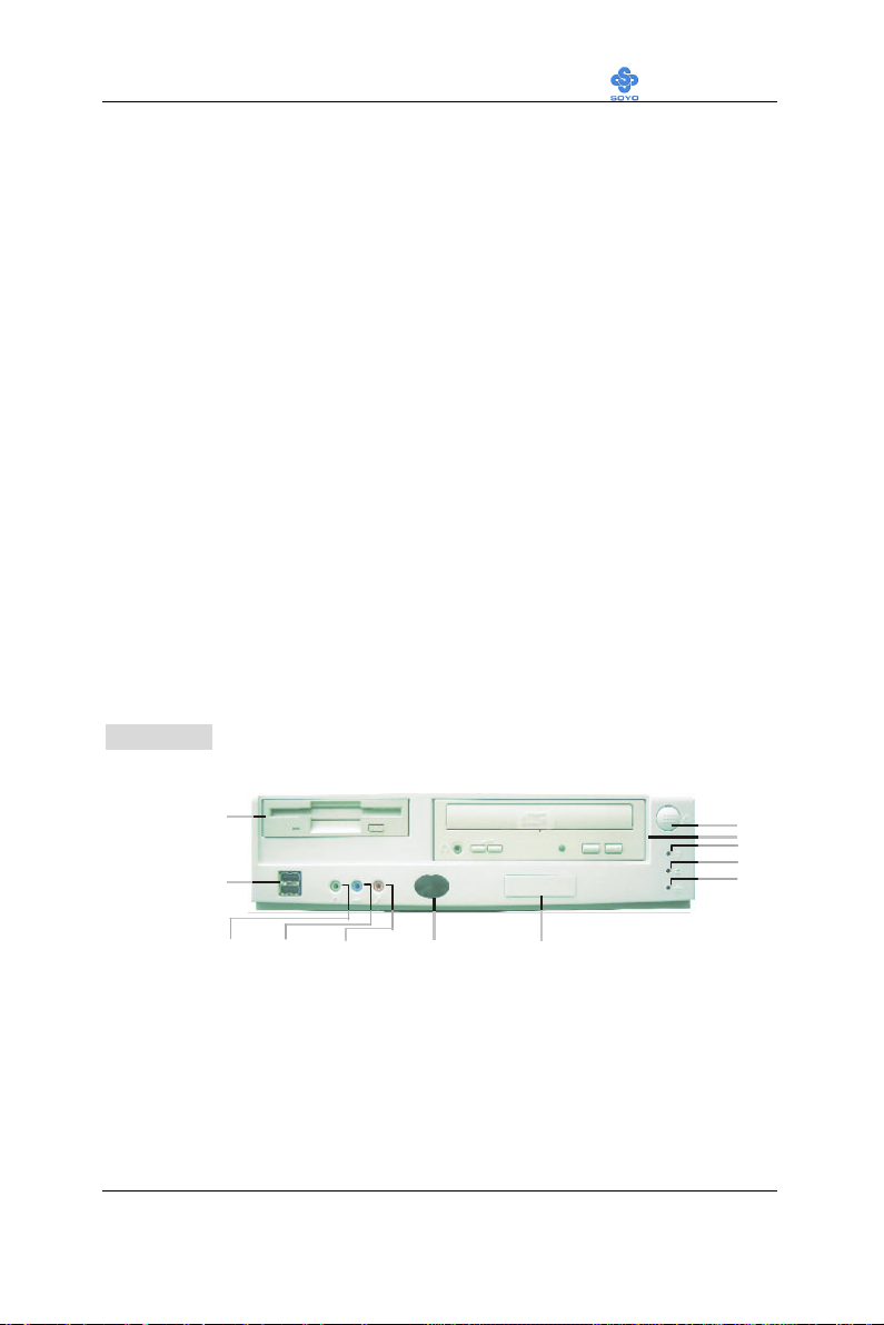
Figure 1. Front Panel
Floppy Drive Mounting Bay
USB Ports
Power Button
CD-ROM Mounting Bay
Power LED
HDD LED
LAN LED
IR WindowsLINE-OUT LINE-IN MIC JACK
Detachable Loge Plate
1
Page 6
Introduction LI-7000
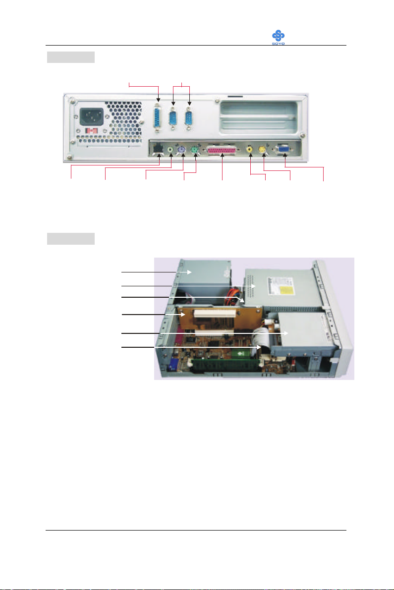
Serial Port
Game Port
Parallel Port
Mouse
LINE-OUT
LAN
TV-OUT
S-OUT
VGA Port
Figure 2. Back Panel
Keyboard
Figure 3. Inside Look
150W SFX Power Supply
CD-ROM
HDD
Riser Card
Socket 370 CPU
FDD
2
Page 7
Introduction LI-7000
LINE-IN
IR Module
To 7IWL-T Motherboard
Riser Card
AMR
3V
Lithium
1
1
1
FDC
ATX Power
Socket 370
CMOS Clear
DIMM 1
DIMM 2
1
4
4
CODEC
1
3
CPUFAN
Intel
FW82810
1
2
20
10
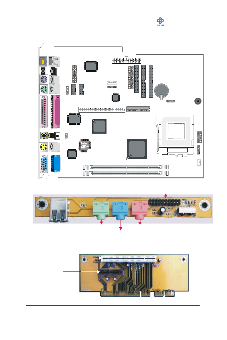
1. SY-7IWL-T Motherboard Layout
LAN
Connector
LINE-OUT
PS/2 KB
Connector
PS/2 Mouse
Connector
PRT
AV onnector for
TV-Out
S-Video
Connector
VGA
Game Port
JP1
3
1
COM1COM2
LAN Chip
Realtek
8139B
J2
J3
1
Front Panel
Connector
AC97
PCI Slot
LPC
W83627HF
-AW
J8
TV-Out
Chip
Intel
FW82801
Battery
IDE 2 IDE 1
JP5
Jumper
Buzzer
JP15
2
2
JP10
910
9
1
4
1
1
2. Front Panel Board
USBLINE-OUT
MIC JACK
3. Riser Card
PCI Slot
AMR Slot
3
Page 8
Introduction LI-7000
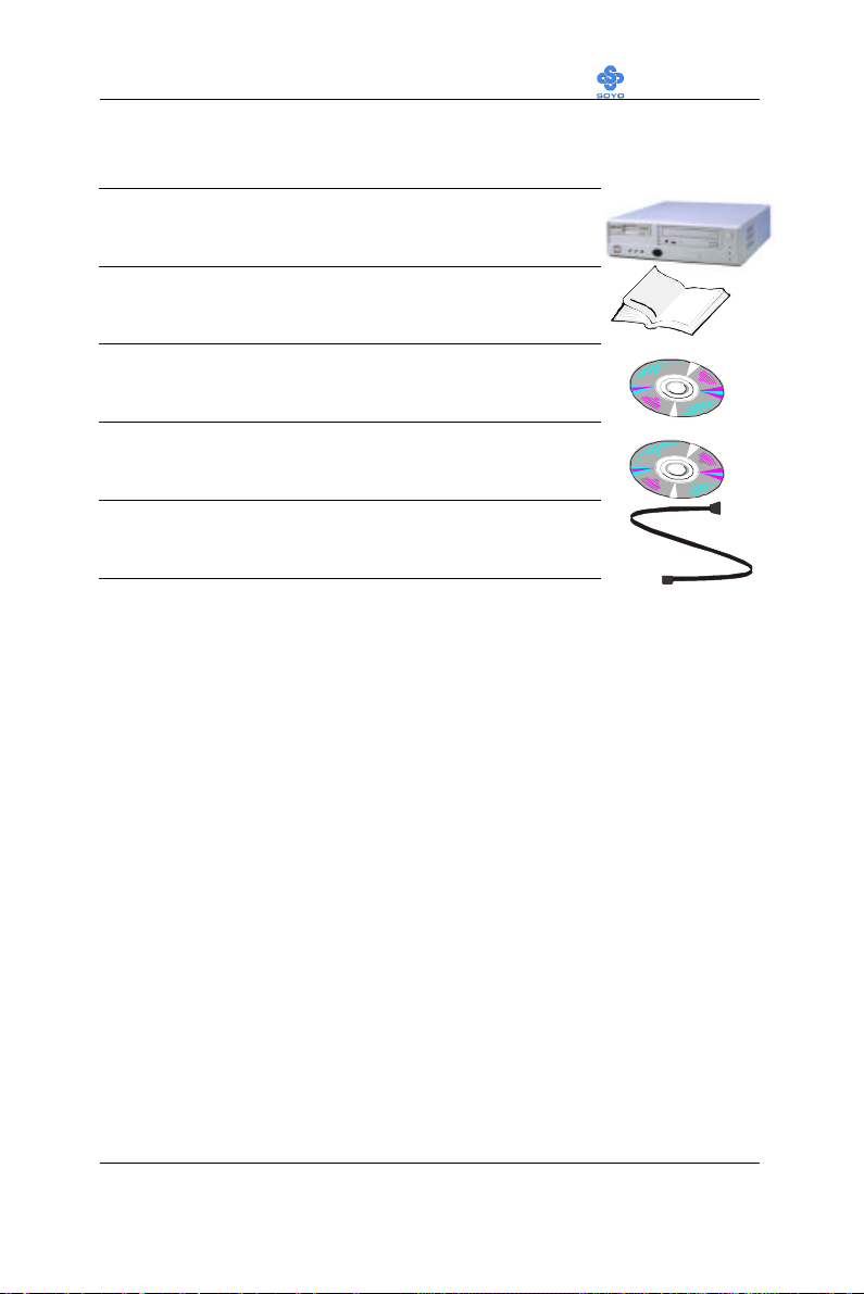
1-3 UNPACKING
When unpacking the System, check for the following items:
u The LI-7000 System
u The Quick Start Guide
u The Installation CD-ROM
u SOYO 3-in-1 Bonus Pack CD-ROM (Norton
AntiVirus, Ghost and Virtual Drive)
u Power Cord
Like most electronic equipment, your Motherboard and other components
and devices may be damaged by electrostatic discharge. To avoid
permanent damage to components ground yourself while working by using
a grounding strap. Otherwise, ground yourself frequently by touching the
unpainted portion of the computer chassis to drain the static charges.
4
Page 9

Motherboard Description LI-7000
Chapter 2
MOTHEBOARD DESCRIPTION
2-1 INTRODUCTION
The SY-7IWL-T AGP/PCI/AMR Motherboard is a high-performance
Socket 370 processor supported Custom LPX form-factor system board.
SY-7IWL-T uses the FW82810 Chipset technology and supports Socket
370 processors. This Motherboard is fully compatible with industry
standards and adds many technical enhancements.
2-2 KEY FEATURES
Ø Supports Intel Celeron™ processors (300A-500MHz)
Ø Supports 100 & 66 MHz Front Side Bus Frequency
Ø Auto detect CPU bus Frequency (66/100)
Ø Auto-detect CPU voltage
Ø Chipset integrated 3D AGP Accelerator
Ø Easy CPU settings in BIOS with the “SOYO COMBO Setup”
Ø PC98, ACPI
Ø Ultra DMA33/66 (ATA 33/66)
Ø Supports ACPI Suspend Indicator
Ø Power-on by modem, alarm, PS/2 Keyboard and Mouse
Ø Supports Wake-On-LAN Function
Ø Supports Onboard PCI LAN Realtek 8139B 10/100Mb/s
Ø Supports TV-out (NTSC/PAL)
Ø Supports AC97 Codec software audio
Ø Supports onboard hardware monitoring and includes Hardware
Doctor™ utility
Ø Power failure resume
5
Page 10

Motherboard Description LI-7000
Ø Fan speed control
Ø Battery Low voltage Detect
Ø Support 7 sets of voltage monitoring
Ø Supports multiple-boot function
Ø Y2K Complaint
Ø Supports Audio Modem Riser slot (AMR 1.0 compliant)
Ø 1 x 32-bit bus mastering PCI slot
Ø 2 x USB ports onboard
Ø 1 x IrDA Device
Ø ATX power connector
Ø Hardware Random Number Generator (RNG) for enabling enhanced
platform security
Ø RTC hardware to handle Y2K Century Rollover
* If the user wants to use a Modem Riser card (MR) make sure to use a
MR,
PRIMARY
mode MRs are
NOT
Supported.
6
Secondary
mode
Page 11

Motherboard Description LI-7000
2-3 HANDLING THE MOTHERBOARD
To avoid damage to your Motherboard, follow these simple rules while
unpacking:
Ø Before handling the Motherboard, ground yourself by grasping an
unpainted portion of the system's metal chassis.
Ø Remove the Motherboard from its anti-static packaging. Hold the
Motherboard by the edges and avoid touching its components.
Ø Check the Motherboard for damage. If any chip appears loose, press
carefully to seat it firmly in its socket.
Warning: Do not apply power if the Motherboard appears
damaged. If there is damage to the board, contact your dealer
immediately.
2-4 ELECTROSTATIC DISCHARGE PRECAUTIONS
Make sure to ground yourself before handling the Motherboard or other
system components. Electrostatic discharge can easily damage the
components. Note that you must take special precautions when handling
the Motherboard in dry or air-conditioned environment.
To protect your equipment from electrostatic discharge, take the following
precautions:
Ø Do not remove the anti-static packaging until you are ready to install.
Ø Ground yourself before removing any system component from its
protective anti-static packaging. (To ground yourself, grasp the expansion
slot covers or other unpainted portions of the computer chassis.)
Ø Frequently ground yourself while working or use a grounding strap.
Ø Handle the Motherboard by its edges and avoid touching its
components.
7
Page 12
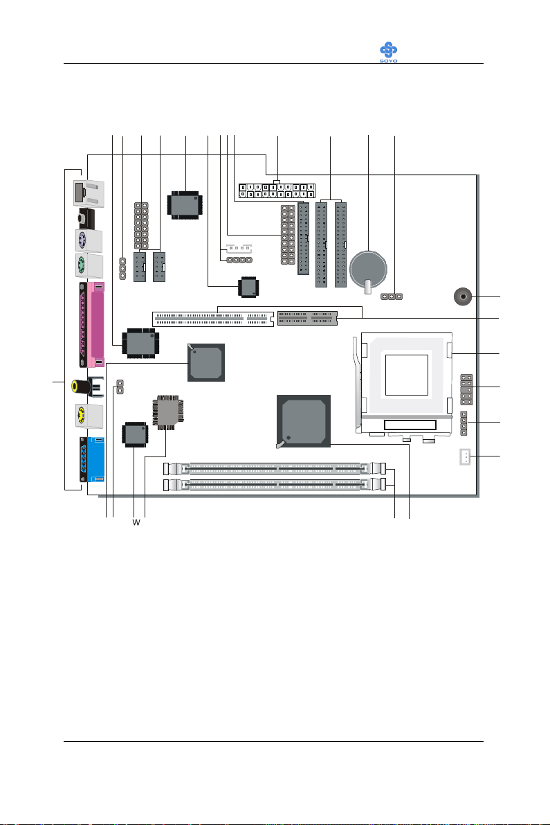
Motherboard Description LI-7000
ABCDEFGHIJKLMNO
R
S
TUX
Y
V
2-5 SY-7IWL-T MOTHERBOARD COMPONENTS
P
Z
Q
8
Page 13

Motherboard Description LI-7000
A Winbond W83627HF-AW LPC I/O Chip
B Power-On by Keyboard Jumper
C Game Port Connector
D COM1/COM2 Connector
E Realtek 8139B LAN Chip
F AC97 Codec Chip
G CD-IN Connector
H Front panel connectors
I Floppy Disk Drive (FDD) Port
J ATX Power Supply Connector
K Bus Mastering E-IDE/ATAPI Ports
L 3V Lithium Battery
M CMOS Clear Jumper
N Buzzer
O Riser-Card Slot
P Socket 370 Connector
Q Power-button & Front Panel LED Connector
R Speaker Connector
S CPU Cooling Fan Connector
T Intel FW82810 GMCH Chip
U DIMM Sockets
V Intel 82802AB 4Mb FWH Chip
W TV-Out Chip
X TV-Out Signal Format Jumper
Y Intel FW82801 ICH Chip
Z Back panel Connectors
9
Page 14

Motherboard Description LI-7000
2-6 CHIPSET
To compliment the Intel® Celeron processor, the Intel® 810 chipsets
delivers a balanced platform solution for value computing. The 810
chipset is a highly-integrated three-chip solution consisting of a Graphics
& Memory Controller (Intel 82810), an I/O Controller (Intel82801), and a
Firmware Hub (Intel 82802).
The ICH is a highly integrated multifunctional I/O Controller Hub that
provides the interface to the PCI Bus and integrates many of the functions
needed in today PC platforms. The ICH communicates with the host
controller over a dedicated hub interface. There are two versions of the
ICH (82801AA: ICH and 82801AB: ICH0). These devices are pin
compatible and are in 241-pin packages.
The Intel® 82802 Firmware Hub (FWH) component is part of the Intel®
810 chipset. The FWH is key to enabling future security and
manageabilily infrastructures for the PC platform.
Intel has developed technology that enhances the performance and
exceptional value of the Intel® Celeron™ processor-powered PC. Built on
the strong foundation of Intel® 440BX AGPset technology, the Intel® 810
chipset has re-engineered the Value PC, providing next generation features
and great graphics performance at a lower cost.
Richer, more robust 2D and 3D graphics are optimized thanks to an
integrated chipset design that utilizes second-generation graphics
technology. This integrated chipset offers innovative features with
compelling performance while lowering overall system costs.
A new design with big benefits
At the core of the 810 chipset is a memory controller with built-in graphics
10
Page 15

Motherboard Description LI-7000
technology. The 82810 chip optimizes system memory arbitration, similar
to AGP technology, resulting in a more responsive and cost-effective
system.
The 82810 Graphics Memory Controller Hub (GMCH) features Intel®
graphics technology and software drivers, using Direct AGP (integrated
AGP) to create vivid 2D and 3D effects and images. The 82810 chip
features integrated Hardware Motion Compensation to improve soft DVD
video quality and a digital video out port that enables connection to
traditional TVs or the new space-saving digital flat panel displays.
Intel® Dynamic Video Memory Technology (D.V.M.T.) is an architecture
that offers breakthrough performance for the Value PC segment through
efficient memory utilization and Direct AGP. The system OS uses the Intel
software drivers and intelligent memory arbiter to support richer graphics
applications.
The System Manageability Bus allows networking equipment to monitor
the 810 chipset platform. Using ACPI specifications, the system
manageability function enables low-power sleep mode and conserves
energy when the system is idle.
The 82801 I/O Controller Hub (ICH) employs the Intel® Accelerated Hub
Architecture to make a direct connection from the graphics and memory to
the integrated AC97 controller, the IDE controllers, dual USB ports, and
PCI add-in cards.
The Accelerated Hub Architecture provides twice the bandwidth of the
PCI bus at 266 MB per second. This allows a wider flow of rich
information from the I/O controller to the memory controller, with
optimized arbitration rules allowing more functions to run concurrently,
enabling more life-like audio and video.
11
Page 16

Motherboard Description LI-7000
The Integrated Audio-Codec 97 controller enables software audio and
modem by using the processor to run sound and modem software. By
reusing existing system resources, this feature adds flexibility, and
improves sound quality.
The 82802 Firmware Hub (FWH) stores system BIOS and video BIOS,
eliminating a redundant nonvolatile memory component. In addition, the
82802 contains a hardware Random Number Generator (RNG). The
Intel® RNG provides truly random numbers to enable fundamental
security building blocks supporting stronger encryption, digital signing,
and security protocols.
Intel 810 chipset re-engineers the Value PC by providing a platform that
will bring next generation features and great graphics performance to
Value PC while reducing overall platform cost.
PRODUCT HIGHLIGHTS
Ø Enhances performance and exceptional value of the Intel® Celeron™
processor-powered PC
Ø Built on strong foundation of Intel® 440Bx technology
Ø Provides next generation features
Ø Provides great graphics performance at a lower cost
Ø Optimizes 2D and 3D graphics through integrated chipset design
utilizing second-generation graphics technology
Ø Innovative features with compelling performance while lowering
system costs
FEATURES BENEFITS
Ø Intel® Accelerated Hub Architecture Increased I/O performance
allows better concurrency for richer multimedia applications
Ø Integrated graphics/AC97 controller, more flexibility and better audio
quality
Ø Intel® 3D graphics with Direct AGP Vivid 2D and 3D graphics,
12
Page 17

Motherboard Description LI-7000
efficient use of system memory for graphics, O/S and applications
Ø Optional 4MB of dedicated display cache video memory Enables
SKU differentiation with increased 3D graphics performance
improvement over Direct AGP
Ø Low-power sleep modes Energy Savings
Ø One software driver code base More stable platform, higher quality
graphics, reduced OEM support costs
Ø Intel® Random Number Generator (RNG) Enables ISV's to
strengthen security products
Ø Digital Video Out port Allows connection of traditional TV or new
digital flat panel displays; compatible with DVI specification
Ø Soft DVD MPEG 2 playback with Hardware Motion Compensation
Life-like video and audio
Ø 100-MHz System Bus capable Flexibility for performance headroom
Ø 2 USB ports Plug and Play
Ø Multiple Intel® 810 chipset SKUs for Value PC price points Lower
platform and manufacturing costs with single motherboard design
Product Package
Ø 82810 Graphics Memory Controller Hub 421 Ball Grid Array
(BGA)
Ø 82801 Integrated Controller Hub 241 Ball Grid Array (BGA)
Ø 82802 Firmware Hub 32-pin PLCC or 40-pin TSOP
2-6.1 Accelerated Graphics Port (A.G.P.)
A.G.P. is a high-performance bus for graphics-intensive applications, such
as 3D applications. A.G.P., while based on the PCI Local Bus
Specifications, Rev 2.1, is independent of the PCI bus and is intended for
exclusive use with graphical display devices. A.G.P. overcomes certain
limitations of the PCI bus related to handling a large amount of graphics
data with the following features:
l Pipelined memory read and write operations that hide memory access
13
Page 18

Motherboard Description LI-7000
latency
l Demultiplexing of address and data on the bus for near 100 percent
bus efficiency
l AC timing for 133 MHz data transfer rates, allowing real data
throughput in excess of 500 MB/sec
2-6.2 Universal Serial Bus (USB)
The motherboard has two USB ports; one USB peripheral can be
connected to each port. For more than two USB devices, an external hub
can be connected to either port. The motherboard fully supports the
universal host controller interface (UHCI) and used UHCI-compatible
software drivers.
Specification USB features include:
l Self-identifying peripherals that can be plugged in while the
computer is running
l Automatic mapping of function to driver and configuration
l Support for isochronous and asynchronous transfer types over the
same set of wires
l Support for up to 127 physical devices
l Guaranteed bandwidth and low latencies appropriate for telephony,
audio, and other applications
l Error-handling and fault-recovery mechanisms built into the protocol
¿
Note
Computer systems that have an unshielded cable attached to a USB port
may not meet FCC Class B requirements, even if no device or a low-speed
USB device is attached to the cable. Use shielded cable that meets the
requirements for a full-speed USB device.
14
Page 19

Motherboard Description LI-7000
2-6.3 IDE Support
The motherboard has two independent bus-mastering PCI IDE interfaces.
These interfaces support PIO Mode3, PIO Mode 4, ATAPI devices (e.g.,
CD-ROM), and Ultra DMA/33 synchronous-DMA mode transfers. The
BIOS supports logical block addressing (LBA) and extended cylinder head
sector (ECHS) translation modes. The BIOS automatically detects the IDE
device transfer rate and translation mode.
Programmed I/O operations usually require a substantial amount of
processor bandwidth. However, in multitasking operating systems, the
bandwidth freed by bus mastering IDE can be devoted to other tasks while
disk transfers are occurring.
The motherboard also supports laser servo (LS-120) drives. LS-120
technology allows the user to perform read/write operations to LS-120
(120MB) and conventional 1.44MB and 720KB diskettes. An optical
servo system is used to precisely position a dual-gap head to access the
diskett’s 2,490 tracks per inch (tpi) containing up to 120 MB of data
storage. A conventional diskette uses 135 tpi for 1.44 MB of data storage.
LS-120 drivers are ATAPI-compatible and connect to the motherboard’s
IDE interface. (LS-120 drives are also available with SCJSI and parallel
port interfaces.) Some versions of Windows 95 and Windows NT
operating systems recognize the LS-120 drive as a bootable device in both
120 MB and 1.44 MB mode.
Connection of an LS-120 drive and a standard 3.5-inch diskette drive is
allowed. The LS-120 drive can be configured as a boot device if selected
as Drive A in the BIOS setup program.
¿
Note
If you connect at LS-120 drive to an IDE connector and configure it as
the :boot: drive and configure a standard 3.5-inch diskette drive as a “B”
drive, the standard diskette drive is not seen by the operating system.
When the LS-120 drive is configured as the “boot: device, the system will
recognize it as both the A and B drive
15
Page 20

Motherboard Description LI-7000
2-6.4 Real-Time Clock, CMOS SRAM, and Battery
The real-time clock is compatible with DS1287 and MC146818
components. The clock provides a time-of-day clock and a multicentury
calendar with alarm features and century rollover. The real-time clock
supports 256 bytes of battery-backed CMOS SRAM in two banks that are
reserved for BIOS use.
The time, date, and CMOS values can be specified in the Setup program.
The CMOS values can be returned to their defaults by using the Setup
program.
2-7 I/O INTERFACE CONTROLLER
The motherboard uses the Winbond W83627HF-AW I/O controller which
features:
l Single diskette drive interface
l Two serial ports
l FIFO supports on both serial and diskette interfaces
l One parallel port with Extended Capabilities Port (ECP) and
Enhanced Parallel Port (EPP) support
l PS/2 style mouse and keyboard interfaces
l PCI PME interface
l Intelligent auto power management, including:
Ø Shadowed write-only registers for ACPI compliance
Ø Programmable wake-up event interface
The Setup program provides configuration option for the I/O controller.
2-7.1 Serial Ports
The motherboard has one 9-pin D-Sub serial port connector located on the
back panel. The NS16C5450-compatible UARTs support data transfers at
speeds up to 115.2 Kbits/sec with BIOS support.
2-7.2 Parallel Port
The connector for the multimode bi-directional parallel port is a 25-pin DSub connector located on the back panel of the motherboard. In the Setup
16
Page 21

Motherboard Description LI-7000
program, there are four options for parallel port operation:
l Compatible (standard mode)
l Bi-directional (PS/2 compatible)
l Bi-directional EPP. A driver from the peripheral manufacturer is
required for operation. See Section 6.2 for EPP compatibility.
l Bi-directional high-speed ECP
2-7.3 Diskette Drive Controller
The I/O controller is software compatible with the 82077 diskette drive
controller and supports both PC-AT and PS/2 modes. In the Setup
program, the diskette drive interface can be configured for the following
diskette drive capacities and sizes.
l 360 KB, 5.25-inch
l 1.2 MB, 5.25-inch
l 720 KB, 3.5-inch
l 1.2 MB. 3.5-inch (driver required)
l 1.25-1.44 MB, 3.5-inch
l 2.88 MB, 3.5-inch
2-7.4 PS/2 Keyboard and Mouse Interface
PS/2 keyboard and mouse connectors are located on the back panel of the
motherboard. The +5 V lines to these connectors are protected with a fuse
circuit that, like a self-healing fuse, reestablishes the connection after an
over-current condition is removed.
¿
Note
The mouse and keyboard can be plugged into either PS/2 connector.
Power to the computer should be turned off before a keyboard or mouse is
connected or disconnected.
The keyboard controller contains code, which provides the traditional
keyboard and mouse control functions, and also supports Power On/Reset
password protection. Power On/Reset password can be specified in the
BIOS Setup program.
17
Page 22

Motherboard Description LI-7000
The keyboard controller also supports the hot-key sequence
<Ctrl><Alt><Del>, software reset. This key sequence resets the
computer’s software by jumping to the beginning of the BIOS code and
running the Power On Self Test (POST).
2-7.5 Infrared Support
The IR connection can be used to transfer files to or from portable devices
like laptops, PDAs, and printers.
2-8 AUDIO SUBSYSTEM
2-8.1 Audio Connector
The audio connectors include the following:
l Back panel connectors: stereo line-level output (Line Out), stereo
line-level input (Line In), and Mic In
2-8.1.1 CD Line - in Connector
A1 x 4-pin ATAPI-style connector is available for connecting an internal
CD-ROM drive to the audio mixer. The connector is designed for use with
cables that are compatible with ATAPI CD-ROM drivers
2-9 HARDWARE MONITOR
The optional hardware monitor subsystem provides low-cost
instrumentation capabilities. The features of the hardware monitor
subsystem include:
Ø An integrated ambient temperature sensor
Ø Fan speed sensors, which monitor the fan 1 and fan 2 connectors
Ø Power supply voltage monitoring to detect levels above or below
acceptable values
When suggested ratings for temperature, fan speed, or voltage are
exceeded, an interrupt is activated. The hardware monitor component
connects to the SMBus.
18
Page 23

Motherboard Description LI-7000
2-10 WAKE ON LAN TECHNOLOGY
Wake on LAN technology enables remote wakeup of the computer
through a network. The LAN subsystem, whether onboard or as a PCI bus
network adapter, monitors network traffic at the Media Independent
Interface. Upon detecting a Magic Packet= frame, the LAN subsystem
asserts a wakeup signal that powers up the computer. Depending on the
LAN implementation, the motherboard board supports Wake on LAN
technology in one of two ways:
Ø Through the Wake on LAN technology connector
Ø Through the PCI bus PME# signal (for PCI2.2 compliant LAN
designs)
The Wake on LAN technology connector can be used with PCI bus
network adapters that have a remote wake up connector, Network adapters
that are PCI 2.2 compliant assert the wakeup signal through the PCI bus
signal PME# (pin A19 on the PCI bus connectors).
Note:This motherboard supports remote wakeup using the PME#
signal; the WOL connector is not supported.
The onboard LAN subsystem also supports remote wakeup using the
PME# signal.
*
CAUTION
For Wake on LAN, the 5-V standby line for the power supply must be
capable of delivering +5V ±5 % at 720 mA. Failure to provide adequate
standby current when implementing Wake on LAN can damage the power
supply.
19
Page 24

Motherboard’s Hardware Installation LI-7000
Chapter 3
MOTHERBOARD’ S HARDWARE INSTALLATION
3-1 PREPARATIONS
Gather and prepare all the following hardware equipment to complete the
installation successfully:
u CeleronTM Socker370 processor with CPU cooling fan*
u SDRAM module
u Monitor
u Keyboard
u Mouse
u Speaker(s) (optional)
u Disk Drives: HDD, CD-ROM, Floppy drive…
u External Peripherals: Printer, Plotter, and Modem (optional)
u Internal Peripherals: Modem Riser cards (optional)
Note: If you want to use an external speaker connected to "Line-out" port,
please make sure to use an "amplified speaker" that can generate
proper output sound volume.
*Please use appropriate fan and heatsink to avoid the mechanical
conflict with drive bracket.
20
Page 25

Motherboard’s Hardware Installation LI-7000
3-2 MOTHERBOARD INSTALLATION GUIDE
We will now begin the installation of the Motherboard. Please follow the
step-by-step procedure designed to lead you to a complete and correct
installation.
Warning: Turn off the power to the Motherboard, system
chassis, and peripheral devices before performing any work on
the Motherboard or system.
BEGIN THE INSTALLATION
21
Page 26
Motherboard’s Hardware Installation LI-7000
3-2.1 CPU Installation
To perform the installation of your new SY-7IWL-T Motherboard, follow
the steps below:
Mark your CPU Frequency:
your CPU that should be clearly marked on the CPU cover.
300MHz (66 x 4.5) 333MHz (66 x 5.0) 366MHz (66 x 5.5) 400MHz (66 x 6.0)
433MHz (66 x 6.5) 466MHz (66 x7..0) 500MHz (66 x7.5)
This Motherboard is designed to support processors with 100MHz FSB.
However, Socket 370 processors with 100MHz FSB are not available at
present.
Record the working frequency of
CPU Mount Procedure:
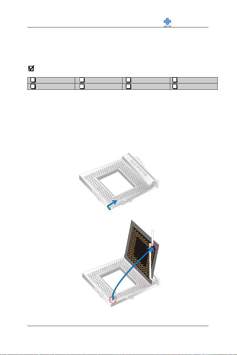
have purchased separately, follow these instructions.
To mount the Celeron TM processor that you
1. Lift the socket handle up to a vertical position.
2. Align the blunt edge of the CPU with the matching pinhole
distinctive edge on the socket.
22
Page 27
Motherboard’s Hardware Installation LI-7000
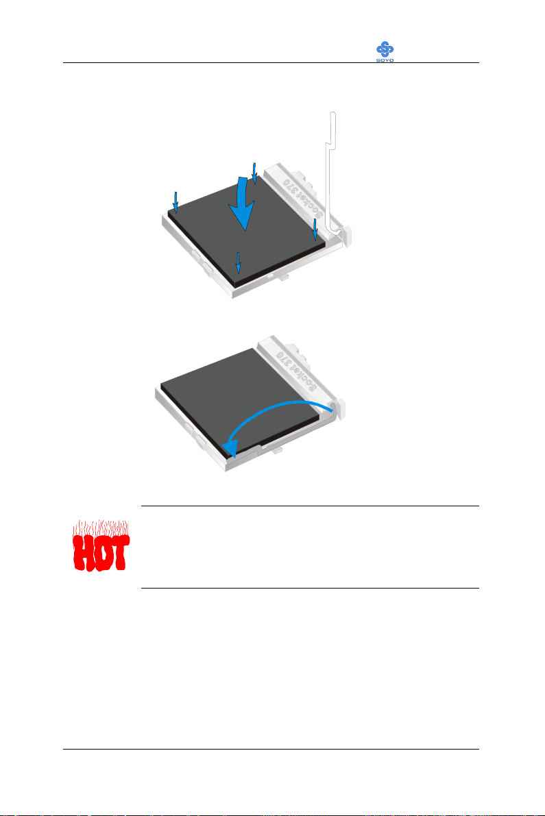
3. Seat the processor in the socket completely and without forcing.
4. Then close the socket handle to secure the CPU in place.
Remember to connect the CPU Cooling Fan to the
appropriate power connector on the Motherboard. The fan is
a key component that will ensure system stability. The fan
prevents overheating, therefore prolonging the life of your
CPU.
23
Page 28
Motherboard’s Hardware Installation LI-7000
1
84
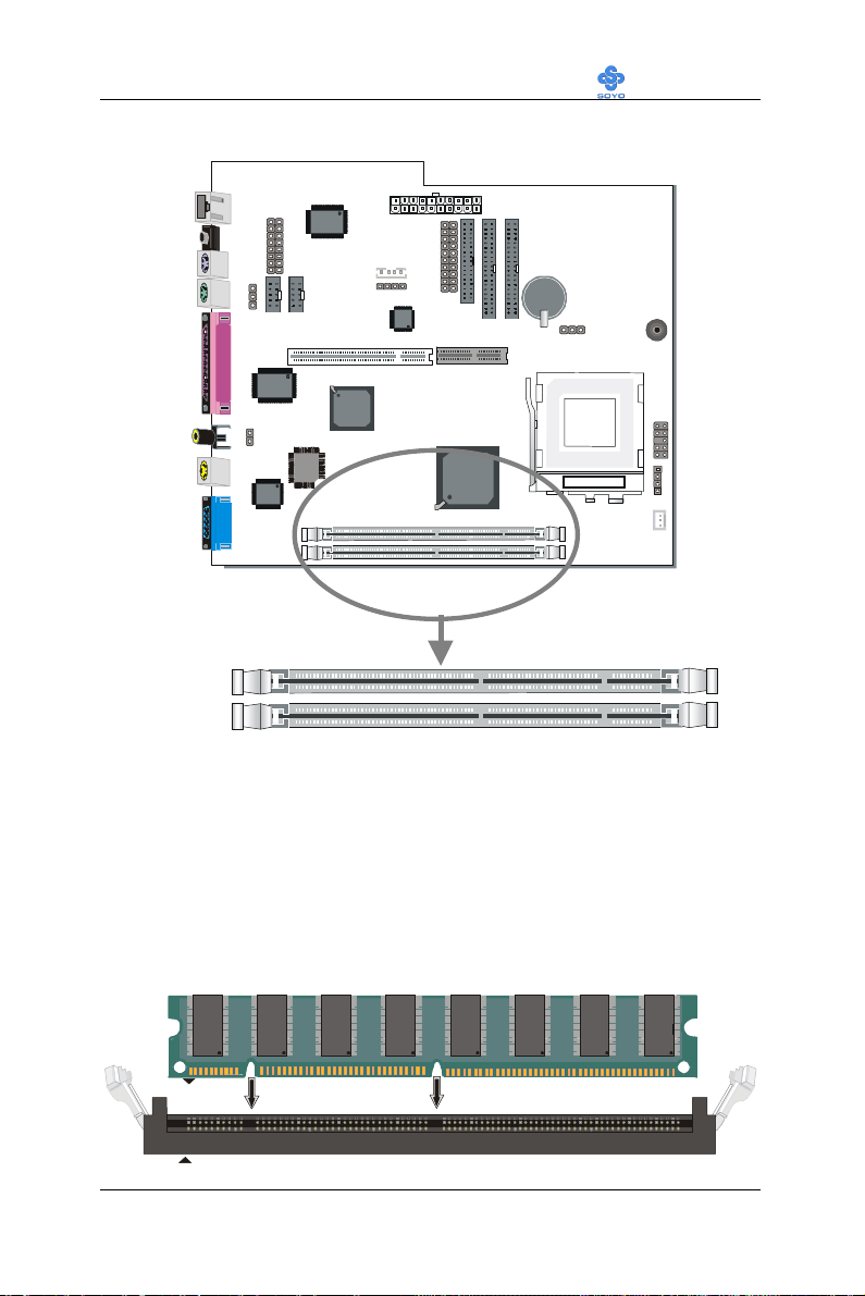
3-2.2 SDRAM Memory Module Installation
DIMM 2
DIMM 1
Your board comes with two DIMM sockets, and supports up to 512MB
main memory using industry standard Synchronous DRAM (SDRAM),
single or double-sided, 3.3V unbuffered DIMM modules from 8MB to
256MB. Registered DIMMs or DIMMs populated with 4 bit wide
SDRAM devices are not supported. PC100 compliant DIMM module is
required regardless of 66 or 100MHz FSB speed.
1
84
24
Page 29
Motherboard’s Hardware Installation LI-7000
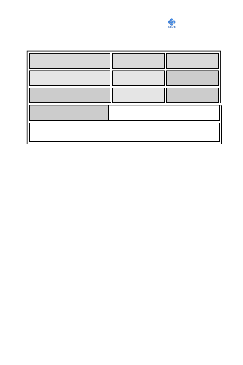
Memory Configuration Table
Number of Memory
Modules
1
2
RAM Type
Memory Module Size (MB)
Note: PC100 Compliant DIMM module is required regardless of 66 or
100 MHz FSB speed.
DIMM 1 DIMM 2
Double-sided/
Single-sided
Double-sided/
Single-sided
Double-sided/
Single-sided
Double-sided/
Single-sided
SDRAM¹
8/16/32/64/256 Mbytes
25
Page 30
Motherboard’s Hardware Installation LI-7000
IDE 2
IDE 1
Pin -1
IDE
39
39
40-pin
80-Conductor
3-2.3 Motherboard Connector
Secondary
Primary
IDE
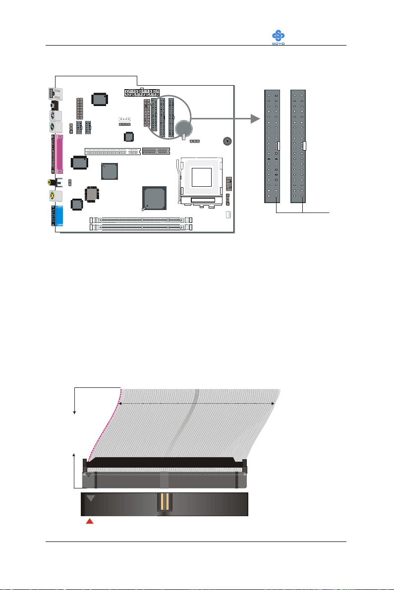
3-2.3.1 IDE Device Installation (HDD, CD-ROM)
This Motherboard offers two primary and secondary IDE device
connectors (IDE1, IDE2). It can support up to four high-speed ATA 33/66
HDD or CD-ROM.
Connect one side of the 40-pin flat cable to the IDE device (HDD or CDROM) and plug the other end to the primary (IDE1) or secondary (IDE2)
directionally keyed IDE connector on the Motherboard.
This Motherboard can support up to four ATA 33/66 IDE devices.
ATA 66
Flat Cable
1
1
26
Page 31
Motherboard’s Hardware Installation LI-7000
33
33
Pin -1
Floppy Drive
Connector
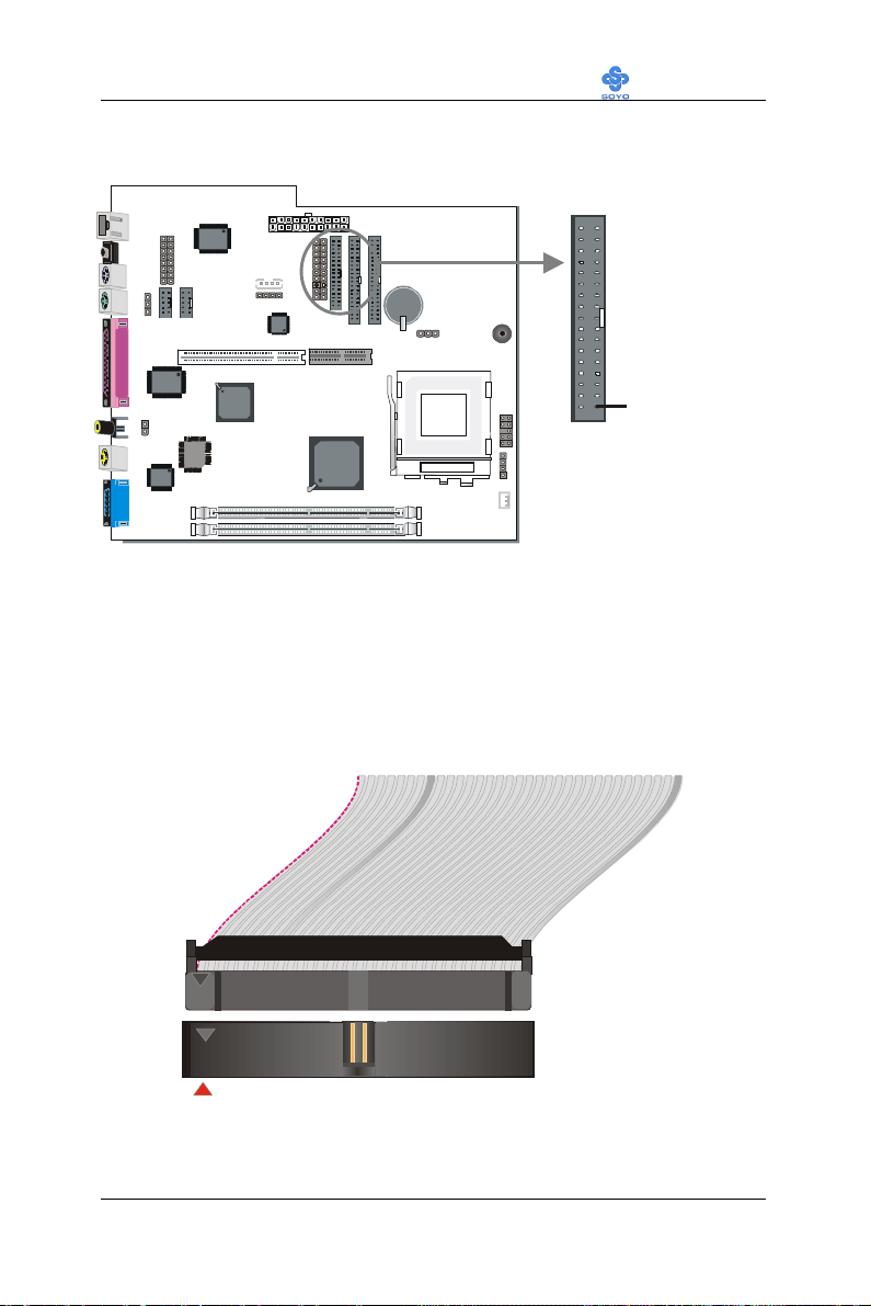
3-2.3.2 Floppy Drive Installation
FDC
The system supports 5 possible floppy drive types: 720 KB, 1.2 MB,
1.44 MB, 2.88 MB, and LS-120. In addition, this Motherboard supports a
3-mode (720KB/1.2MB/1.44MB) floppy commonly used in Japan.
Connect one side of the 34-pin flat cable to the floppy drive and plug the
other end to the floppy drive connector on the Motherboard.
This Motherboard can support up to 2 floppy drives.
1
1
27
Page 32
Motherboard’s Hardware Installation LI-7000
1
3
5
7
9
Front Panel Device : JP16
1
Speaker: JP10
1
3
5
7
9
Mic PWR
LINE L1
USB D0N
USB D0P
1
3
5
7
9
Power Button &
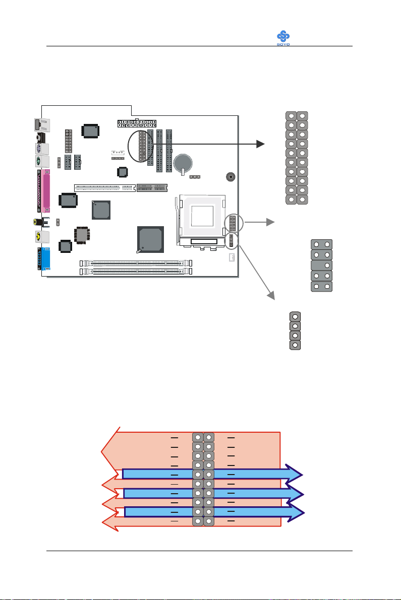
3-2.3.3 Front Panel Connections
20
18
12
10
8
6
4
2
19
17
1516
1314
11
JP15
10
8
6
4
2
4
3
2
1. Front Panel Device: JP16
Plug the computer case's front panel board flat cable connector to this
header. The header by out is as follows:
USB G1
USB
IrDA
GND
Microphone
USB D1P
USB D1N
VCC
ROUT1
LINE R1
Mic In
20
18
12
10
8
6
4
2
28
19
17
1516
1314
11
USB G0
USB V0USBV1
VCC
IRTXIRRX
LOUT1
GNDGND
VCC
LINE-OUT
LINE IN
Page 33
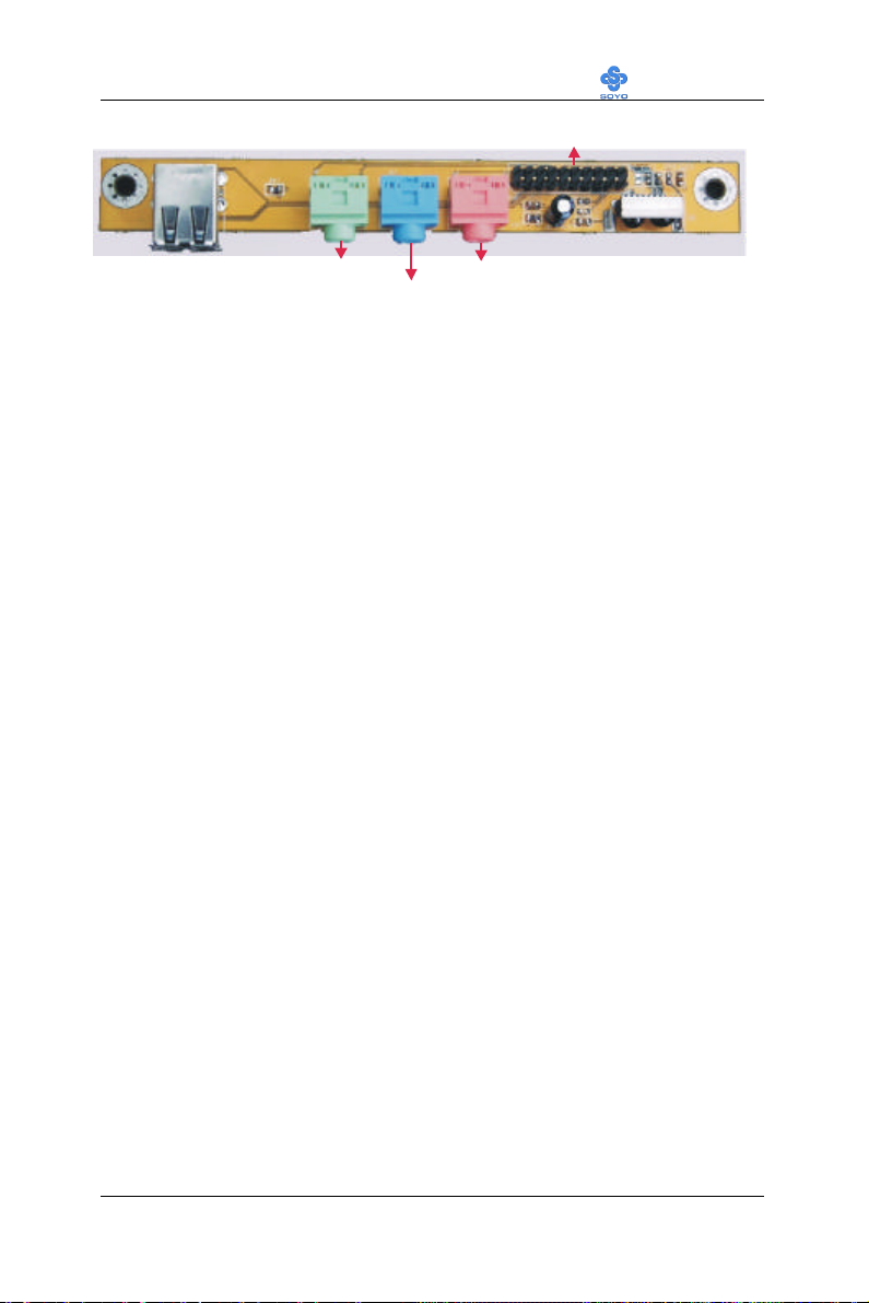
Motherboard’s Hardware Installation LI-7000
LINE-IN
IR Module
To 7IWL-T Motherboard
USBLINE-OUT
MIC JACK
(1). Universal Serial Bus USB1/USB2
This Motherboard provides two USB ports for your additional devices.
Plug the USB device jack into the available USB connector USB1 or
USB2.
- Standard device drivers come with the Win98 for commonly used
USB devices.
- With Win95, use the flow UHCI specifications.
(2). Onboard Joystick port/audio
This Motherboard provides Joystick port and audio.
- Attach the joystick cable to the 15-pin JOYSTICK port at the rear
panel of you motherboard.
- This Motherboard features three built-in audio-stereo ports (labeled
line-in, line-out, and mic jack) convenient to directly plug-in all your
external audio devices.
(3). IR Module
Your case has a build in IR transceiver, connected to the motherboard
through this header. It supports both the ASKIR and HPSIR specifications.
29
Page 34
Motherboard’s Hardware Installation LI-7000
LED 0
LAN LED
Power Button
ACPI LED Pin Assignment
IO SVSB
SVS LED#
None
HDD LED Pin Assignment
VCC
IDEACT#
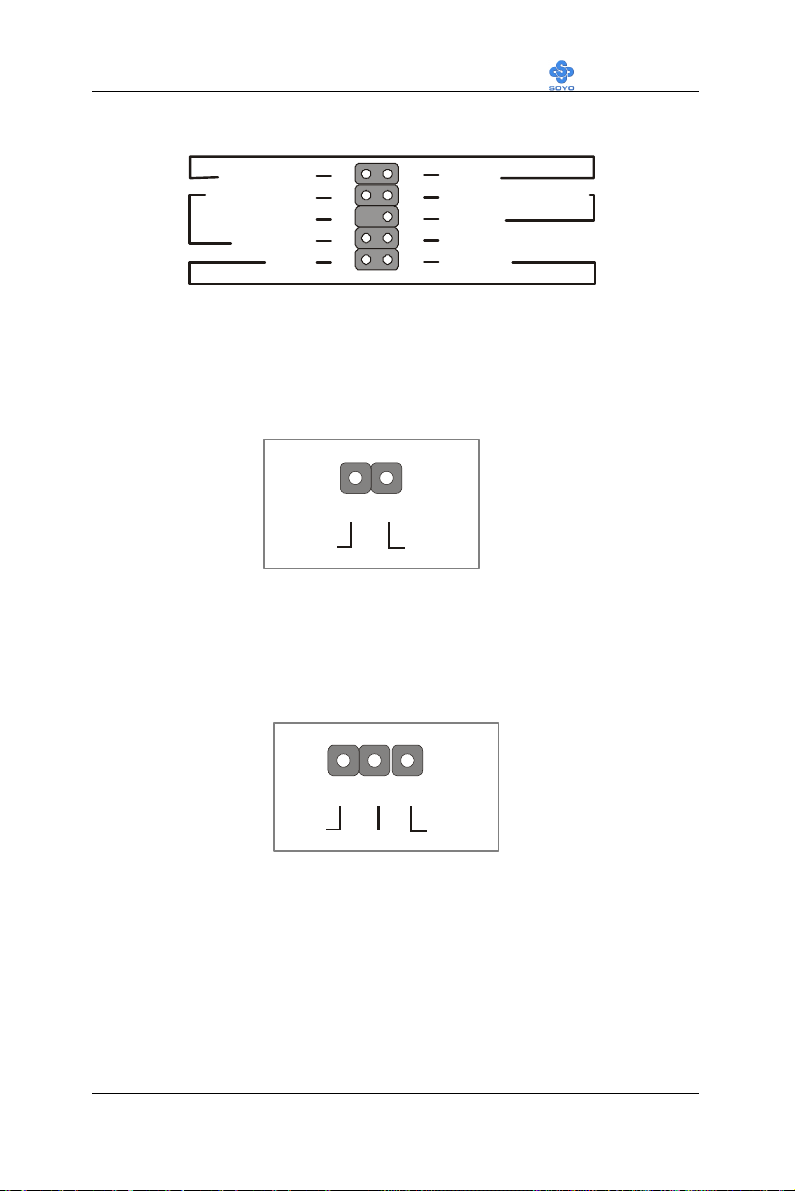
2. Power Button & Front Panel LED: JP15
HDD LED
ACPI LED
IDEACT#
SVS LED #
IOSVSB
VCC
10
8
6
NC
4
2
VCC
9
PWRBTN#LPC
7
5VSB
5
NC
3
1
(1). IDE LED
Attach the 2-pin IDE device LED cable to the corresponding IDE LED
header on the Motherboard. This will cause the LED to lighten when an
IDE (HDD, CD-ROM) device is active.
Pin9
Pin10
(2). ACPI LED
Connecting the 2-pin ACPI LED cable to the corresponding ACPI LED
header will cause the LED to light whenever the system is in ACPI mode.
The manufacturer has permanently set this Motherboard in ACPI mode
due to most hardware and software compliance to ACPI mode.
Pin4 Pin6 Pin8
30
Page 35
Motherboard’s Hardware Installation LI-7000
Speaker Pin Assignment
Speaker out
PWRBT Pin Assignment
5VSB
PWRBTN#LPC
LAN LED Pin Assignment
VCC
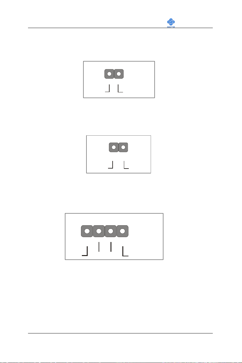
(3). ATX Power On/Off Switch
Attach the 2-pin momentary type switch to the PWRBT header for turning
On or Off your ATX power supply.
Pin5 Pin7
(4). LAN LED
Attach the 2-pin LAN LED connector to this header. The LED will light
up when data is transfer over the network.
Pin1
Pin2
LED 0
3. Speaker (JP10)
Attach the 4-pin PC speaker cable from the case to the Speaker header on
the Motherboard.
+5V
_
+
NC NC
31
Page 36
Motherboard’s Hardware Installation LI-7000
PRT
PS/2 KB
Connector
PS/2 Mouse
VGA
S-Video
Connector
AV onnector for
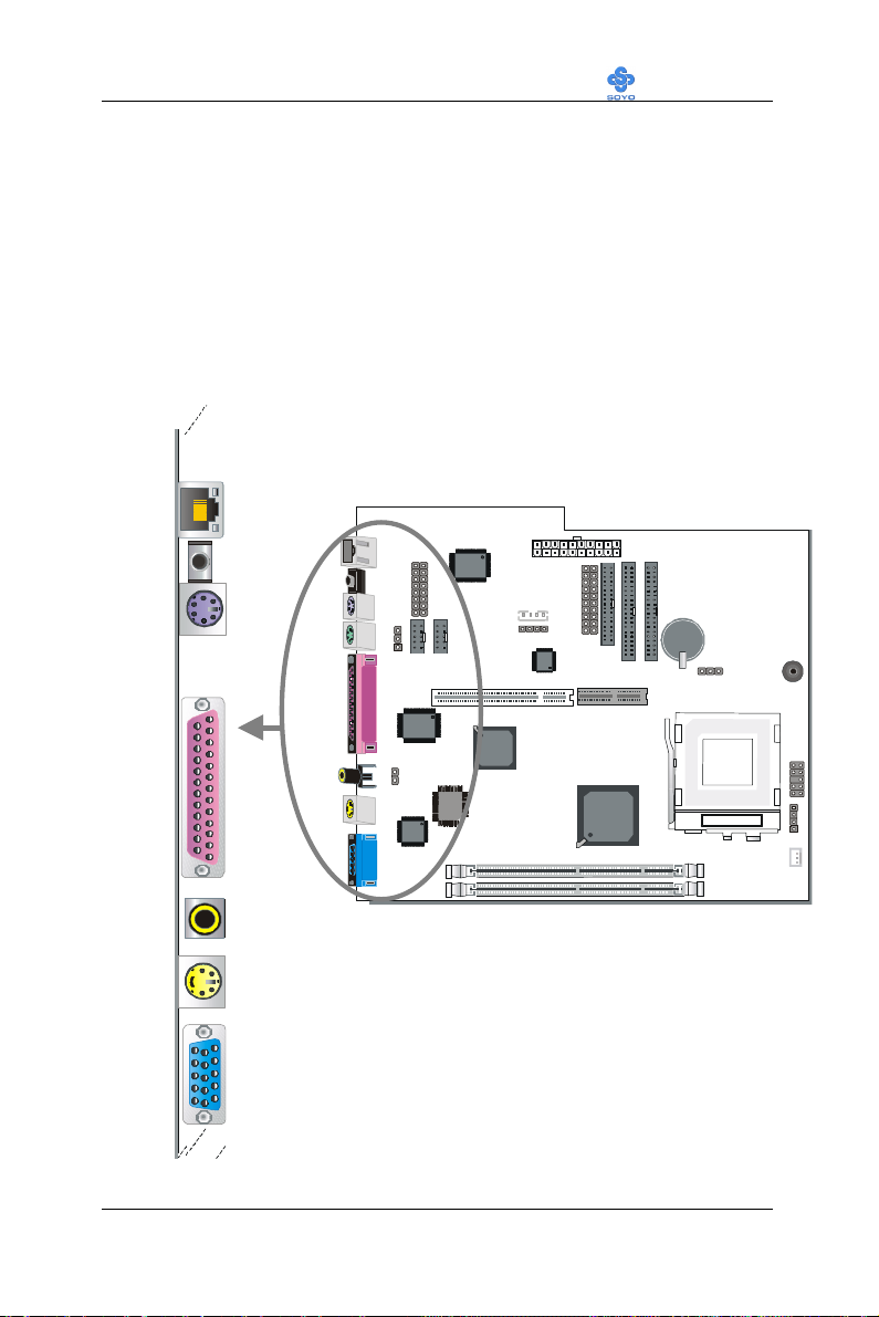
3-2.3.4 Back Panel Connections
All external devices such as the PS/2 keyboard, PS/2 mouse, printer,
modem, USB can be plugged directly onto the Motherboard back panel.
Only after you have fixed and locked the Motherboard to the computer
case can you start connecting the external peripheral devices.
When connecting an external device, use the following figure to locate and
identify which back panel connector to plug the device to.
LAN
Connector
LINE-OUT
Connector
TV-Out
32
Page 37
Motherboard’s Hardware Installation LI-7000
Pin5
KBD Clock
1
2
3
4
5
6
TX+
RX+
TX-
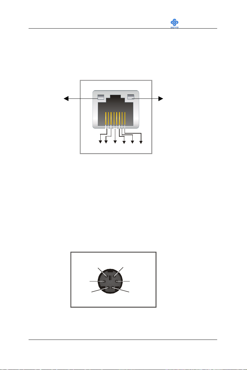
1. LAN Connector
This is the network connector, supporting 10/100MHz transfer rates. Make
sure to use the right quality of cable, 100MHz operation requires special
cable, ask you dealer.
TX/RX LINK (10/100)
78
NCRX-NC
2. LINE-OUT
This is a stereo output to which external speakers can be connected. Make
sure to use only Amplified speakers, otherwise the signal level will be too
low.
3. PS/2 Keyboard
Plug the keyboard jack directly into the 6-pin female PS/2 keyboard
connector located at the rear panel of the Motherboard.
Pin4
VCC
Pin2
NC
Pin6
NC
Pin3
GND
Pin1
KBD DATA
33
Page 38
Motherboard’s Hardware Installation LI-7000
Pin5
Mouse Clock
Signal
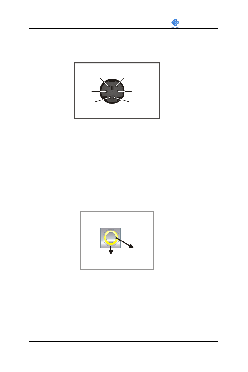
4. PS/2 Mouse
Similarly, plug the mouse jack directly into the 6-pin female PS/2 mouse
connector.
Pin6
NC
Pin4
VCC
Pin2
NC
Pin3
GND
Pin1
Mouse DATA
5. Parallel Port PRT
This parallel port is used to connect the printer or other parallel devices.
Plug the parallel device cable into the 25-pin female connector located at
the rear panel of the Motherboard.
6. AV connector for TV-OUT
Connect your television antenna input to this connector. Make sure to first
set the signal type to the proper value for you Television (NTSC/ PAL).
Under windows this can be changed under display properties after the
driver is installed.
GND
34
Page 39

Motherboard’s Hardware Installation LI-7000
Y
GND
7. S-Video
This output provides a S-Video signal for devices that support this
standard.
C
GND
8. VGA monitor connector
Plug the monitor cable into the 15-pin female VGA connector located at
the real panel of the motherboard.
35
Page 40
Motherboard’s Hardware Installation LI-7000
COM 1
9-pin male external
COM 2
3-2.3.5 Other Connections
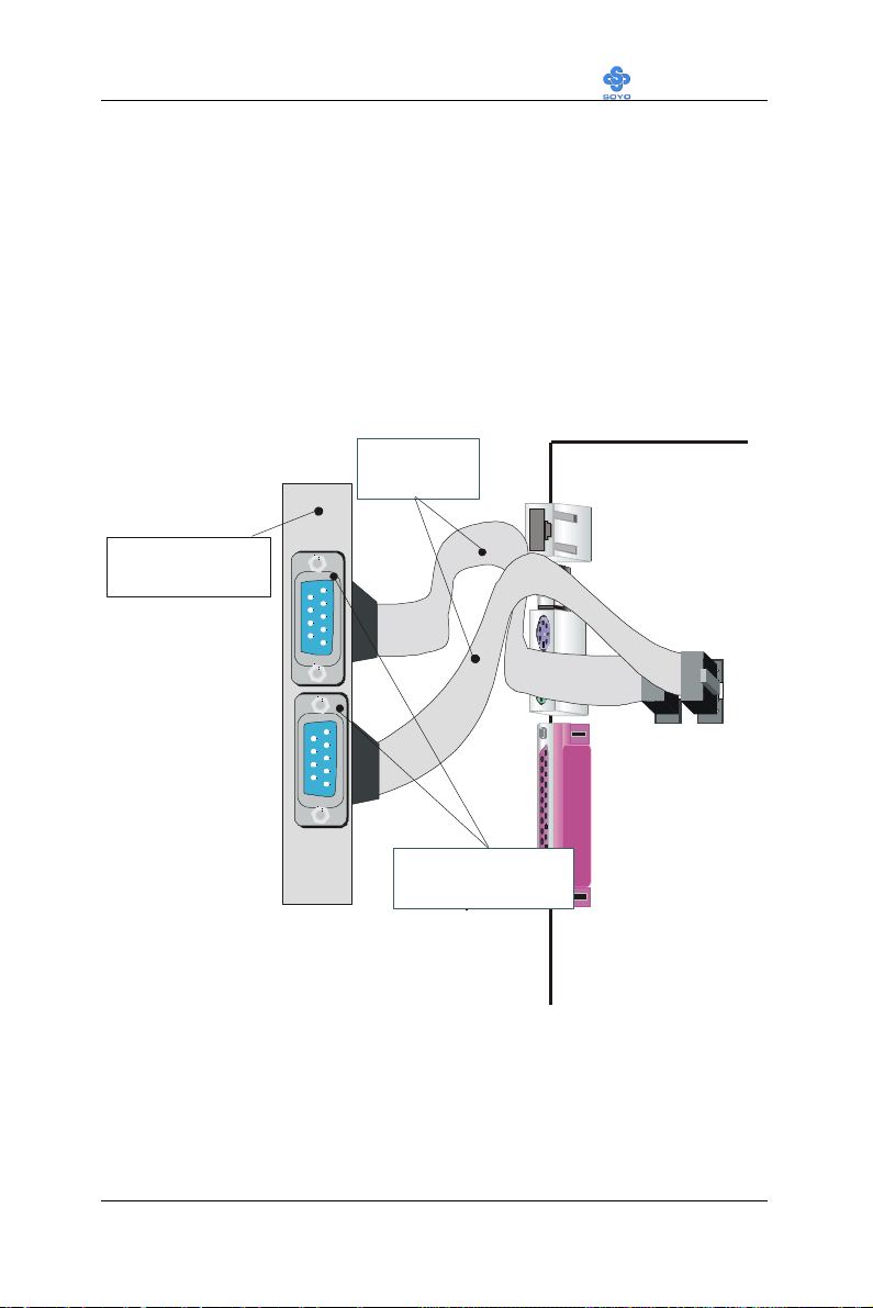
1. Serial Port COM 1 and COM2
This Motherboard provides two serial port connectors.
Plug the 9-pin end of the flat cable into the COM1/COM2 serial port
header on the Motherboard, as shown in the figure below, then fix the
connector to the rear panel of the computer case. Then plug your serial
device cable directly into the 9-pin male connector located at the back of
your computer.
9-pin serial
flat cable
Rear Panel of the
computer case
serial connector
36
Page 41
Motherboard’s Hardware Installation LI-7000
Right
Right
CD Line-in)
Pin Assigment
2. CD Line-in (J2,J3)
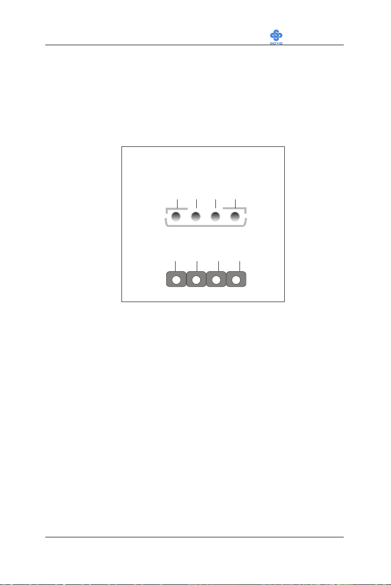
This Motherboard provides two CD-Line in connectors. Please connect the
4-pin audio cable from your CD-ROM drive to either J2 or J3. (It fits in
only one, depending on the cable that came with your CD-ROM drive)
Please install according to the following pin assignment:
J2,J3(
Left
GND
GND
J2
GND
3
GND
4
1 2
Left
J3
1 2 3 4
37
Page 42
Motherboard’s Hardware Installation LI-7000
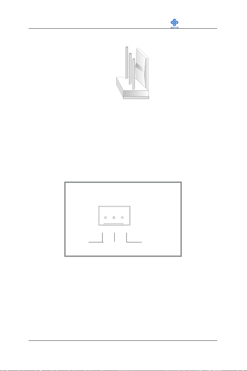
CPU Cooling Fan
CPUFAN Pin Assignment
SENSOR
3. Cooling Fan Installation
(1) CPU Cooling Fan
After you have seated the CPU properly on the processor, attach the 3-pin
fan cable to the CPUFAN connector on the Motherboard. The fan will stop
when the system enters into Suspend Mode. (Suspend mode can be
enabled from the BIOS Setup Utility, [Soyo Combo] menu.)
To avoid damage to the system, install according to the following pin
assignment:
132
12VGND
38
Page 43
Motherboard’s Hardware Installation LI-7000
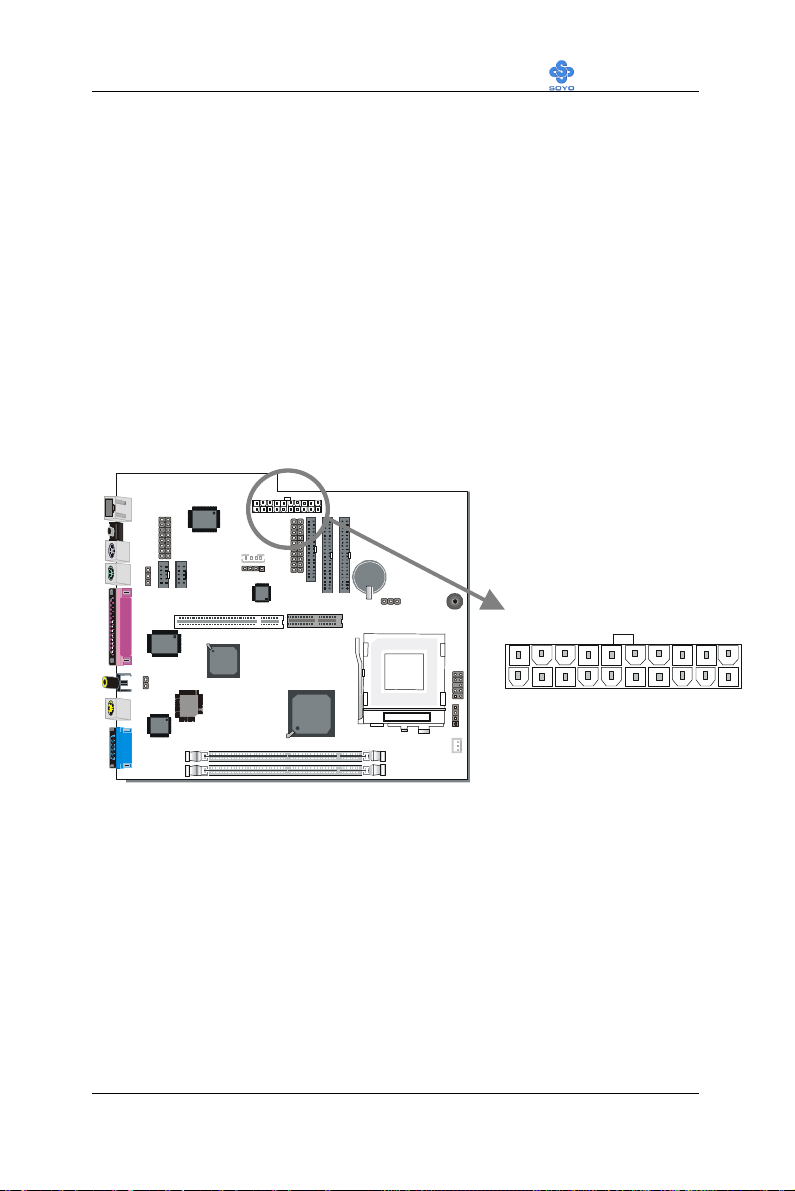
SFX/ATX Power Connector
3-2.3.6 AGP VGA Card
This motherboard comes with integrated AGP subsystem therefore, AGP
VGA card is not needed.
Other Display Cards: Insert other types of VGA cards into the PCI or
ISA expansion slots according to card specifications.
3-2.3.7 SFX/ATX Power Supply
Plug the connector from the power directly into the 20-pin male SFX/ATX
PW connector on the Motherboard, as shown in the following figure.
39
Page 44
Motherboard’s Hardware Installation LI-7000
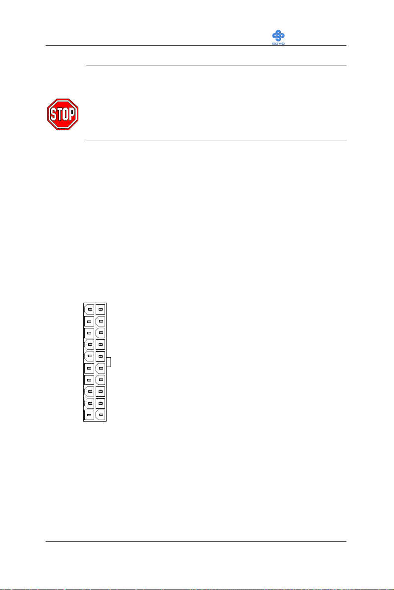
3.3V
-12V
PS-ON
SFX/ATX Power
Warning: Follow these precautions to preserve your
Motherboard from any remnant currents when connecting to
power supply:
Turn off the power supply and unplug the power cord of the
power supply before connecting to PW connector.
This motherboard requires a power supply, that meets the SFX 1.1 or ATX
2.03 specifications. Make sure the power supply can support at least
720mA on the 5V Standby lead.
Please install the SFX/ATX power according to the following pin
assignment:
12V
5VSB
PW-OK
GND
5V
GND
5V
GND
3.3V
3.3V
5V
5V
-5V
GND
GND
GND
GND
Ø (ATX only)
Ø Pay special care to the directionality.
40
Page 45
Motherboard’s Hardware Installation LI-7000
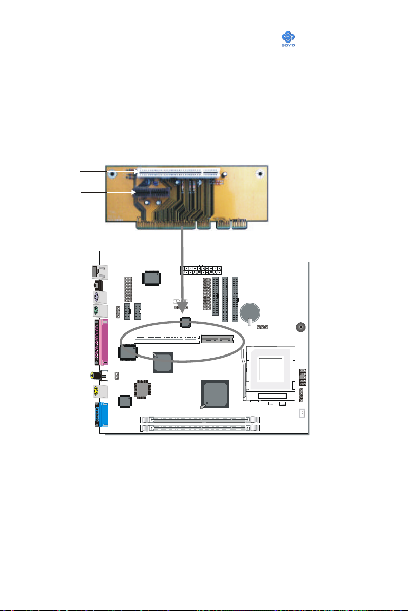
Riser Card
3-2.3.8 AMR (Audio Modem Riser) Connector
This motherboard supports AMR (Audio-Modem Riser) slot that
facilitates audio or modem riser card expansion. Since AC97 audio codec
is built-in down on the motherboard, only “Secondary” mode modem riser
(MR) card can be used on the AMR slot.
PCI Slot
AMR Slot
41
Page 46
Motherboard’s Hardware Installation LI-7000
12312
3
1
2
1
2
115
3-2.4 Jumpers Setting
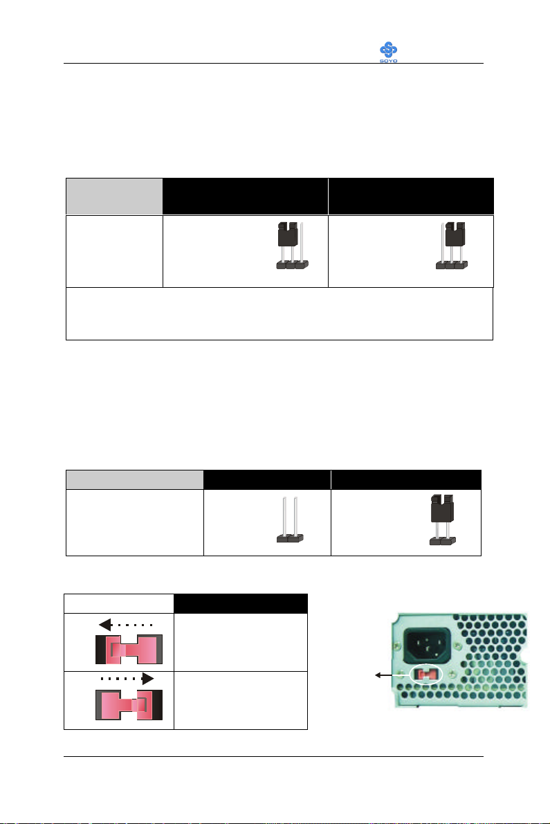
3-2.4.1 Enable/Disable Power-On by Keyboard (JP1)
You may choose to enable the Power-On through Keyboard function by
shorting pin 1-2 on jumper JP1; or short pin 2-3 to disable this function.
Power-On by
Keyboard
JP1 Setting
Short pin 1-2 to
enable the Power-
On by Keyboard
Enable Disable
Short pin 2-3 and
the Power-On by
Keyboard function
function.
is disabled.
Important: When using the Power-On by Keyboard function, please make
sure the power supply is able to provide at least 720mA on the 5V Standby
lead (5VSB).
3-2.4.2 TV-Out signal format (JP8)
The TV-Out connector on your motherboard supports the two most
important video signal formats. i.e., NTSC and PAL. Use JP8 to set the
format used. NTSC is common in the United States, as where PAL is the
European standard.
Video signal format NTSC PAL
JP8 Setting open JP8 short JP8
3-2.4.3 AC line input setting
AC line input range
92~135 Vrms
AC Line
230
180~265 Vrms
42
Page 47
Motherboard’s Hardware Installation LI-7000
123
1
2
3
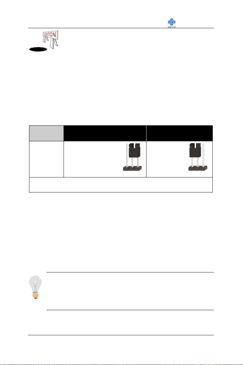
Make sure to set the AC line input appropriately based on
the local electricity supply. Improper setting may cause the
damage of the power supply or system.
3-2.5 CMOS Clearing (JP5)
After you have turned off your computer, clear the CMOS memory by
momentarily shorting pins 2-3 on jumper JP5, for a few seconds. Then
restore JP5 to the initial 1-2 jumper setting in order to recover and retain
the default settings.
Jumper JP5 can be easily identified by its white colored cap.
CMOS
Clearing
JP5 Setting
Clear CMOS Data Retain CMOS Data
Short pin 2-3 for
at least 5 seconds to
clear the CMOS
Short pin 1-2
to retain new
settings
Note: You must unplug the ATX power cable from the ATX power
connector when performing the CMOS Clear operation.
3-2.6 Power On
You have now completed the hardware installation of your Motherboard
successfully.
1. Turn the power on
2. To enter the BIOS Setup Utility, press the <DEL> key while the system
is performing the diagnostic checks.
Note: If you have failed to enter the BIOS, wait until the boot up
sequence is completed. Then push the RESET button and press
<DEL> key again at the beginning of boot-up, during diagnostic
checks.
43
Page 48

Motherboard’s Hardware Installation LI-7000
Repeat this operation until you get the following screen.
3. The BIOS Setup screen appears:
CMOS Setup Utility – Copyright ( C ) 1984-1999 Award Software
4Soyo Combo Feature 4PC Health Status
4Standard CMOS Features Load Optimized Defaults
4Advanced BIOS Features Load Fail - Safe Defaults
4Advanced Chipset Features Set Supervisor Password
4Integrated Peripherals Set User Password
4Power Management Setup Save & Exit Setup
4PnP/PCI Configurations Exit Without Saving
Esc : Quit áâàß : Select Item
F10 : Save & Exit Setup
Change CPU’s Clock & Voltage
3-2.7 Quick BIOS Setup
This Motherboard does not use any hardware jumpers to set the CPU
frequency. Instead, CPU settings are software configurable with the BIOS
[Soyo Combo Feature]. The [Soyo Combo Feature] menu combines the
main parameters that you need to configure, all in one menu, for a quick
setup in BIOS.
After the hardware installation is complete, turn the power switch on, then
press the <DEL> key during the system diagnostic checks to enter the
Award BIOS Setup program. The CMOS SETUP UTILITY will display
on screen. Follow these steps to configure the CPU settings.
SETUP UTILITY will display on screen. Then, follow these steps
to configure the CPU settings.
44
Page 49
Motherboard’s Hardware Installation LI-7000
Step 1. Select [STANDARD CMOS SETUP]
Set [Date/Time] and [Floppy drive type], then set [Hard Disk Type] to
“Auto”.
Step 2. Select [Load Optimized Defaults]
Select the “Load Optimized Defaults” menu and type “Y” at the prompt to
load the BIOS optimal setup.
Step 3. Select [Soyo Combo Feature]
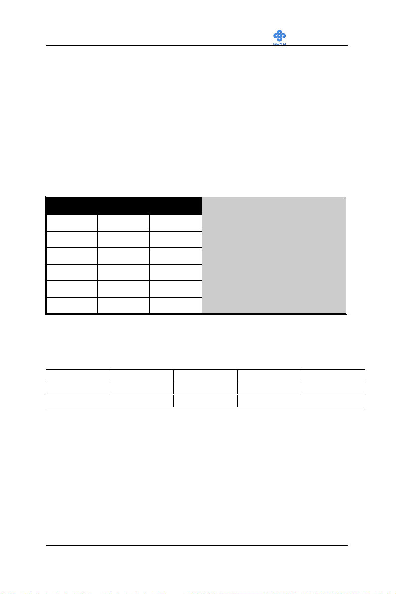
(a) CPU Host/PCI Clock
CPU Host / PCI Clock
o 66/33 o 100/33 o 133/44
o 70/35 o 105/35 o 140/35
The PCI clock frequency depends on
the CPU Host clock. (Fixed pairs in the
clock generator) see the table on the
left side for all possible pairs.
o 75/37 o 114/38 o 150/37
o 83/41 o 120/40
o 90/30 o 124/41
o 95/31 o 133/33
(b) CPU Ratio
After you have selected the CPU Host/ PCI Clock, choose the right
multiplier for the CPU. CPU Ratio options are:
o x 2 o x 2.5 o x 3 o x 3.5 o x 4
o x 4.5 o x 5 o x 5.5 o x 6 o x 6.5
o x 7 o x 7.5 o x 8
The CPU frequency is then defined as [host clock freq.] x [multiplier], and
should the working frequency of your CPUs processor.
Step 4. Select [Save & Exit Setup]
Press <Enter> to save the new configuration to the CMOS memory, and
continue the boot sequence.
45
Page 50

Motherboard’s Hardware Installation LI-7000
3-2.8 Troubleshooting at First Start
l What should I do if the Motherboard refuses to start?
1. Check that all DIMM memory modules are inserted completely.
Sometimes a DIMM that is not inserted properly can cause boot
problems.
2. Check whether all Add-on cards have been inserted properly. Re-
insert the Add-on cards to make sure that they make proper contact
with the slots. Try removing all Add-on cards one by one to see
whether or not one of them is causing problems. (Switch the system
off before removing any of the cards.
3. Verify that speed settings are not exceeding specifications. This
applies to the PCI bus, that is specified to run at 33 MHz. Also check
the speed setting for the memory, make sure conservative setting is
used. If the CPU is overclocked the system may not start up, read the
section below.
4. Make sure that the Harddisk IDE cables are attached properly, if not
the system will not boot. In case of doubt try reversing the IDE
connector on one end of the cable.
5. Verify that the 110/220V switch on the back of the power supply is
set correctly.
6. Go through the jumper setting section again to make sure that all
jumpers are set correctly.
46
Page 51

Motherboard’s Hardware Installation LI-7000
3-2.9 Power Off
There are two possible ways to turn off the system:
1. Use the Shutdown command in the Start Menu of Windows 95/98
to turn off your computer.
2. Press the mechanical power-button and hold down for over 4
seconds, to shutdown the computer. If you press the power-button for
less than 4 seconds, then your system will enter into Suspend Mode.
You are now ready to configure your system with the BIOS setup program.
Go to Chapter 4: BIOS SETUP
47
Page 52

Motherboard’s BIOS Setup Utility LI-7000
Chapter 4
MOTHERBOARD’ S BIOS SETUP UTILITY
This Motherboard's BIOS setup program uses the ROM PCI/ISA BIOS
program from Award Software Inc.
To enter the Award BIOS program's Main Menu:
1. Turn on or reboot the system.
2. After the diagnostic checks, press the [Del] key to enter the Award
BIOS Setup Utility.
CMOS Setup Utility – Copyright ( C ) 1984-1999 Award Software
4Soyo Combo Feature 4PC Health Status
4Standard CMOS Features Load Optimized Defaults
4Advanced BIOS Features Load Fail - Safe Defaults
4Advanced Chipset Features Set Supervisor Password
4Integrated Peripherals Set User Password
4Power Management Setup Save & Exit Setup
4PnP/PCI Configurations Exit Without Saving
Esc : Quit áâàß : Select Item
F10 : Save & Exit Setup
Change CPU’s Clock & Voltage
Selecting items
l Use the arrow keys to move between items and select fields.
l From the Main Menu press arrow keys to enter the selected submenu.
Modifying selected items
l Use the [Up]/[Down] keys to modify values within the selected
fields. Some fields let you enter values directly.
48
Page 53

Motherboard’s BIOS Setup Utility LI-7000
Hot Keys: Function keys give you access to a group of commands
throughout the BIOS utility.
Function Command Description
F1
F5
F6
General Help
Previous
Values
Load FailSafe Defaults
Gives the list of options available for each
item.
Restore the old values. These are the values
that the user started the current session with.
Loads all items with the most conservative
values.
Load
F7
Optimized
Loads all options with the optimize values.
Defaults
F10
[Esc] Exit
[Enter]
Save Saves your changes and reboots the system.
Returns at anytime and from any location to
the Main Menu.
Select
Will display a overlapping window with all
options for the current item.
Using the +, –, Page Up and Page Down
[+/–/PU/PD] Value
keys the user can toggle the value of the
current item.
49
Page 54
Motherboard’s BIOS Setup Utility LI-7000
Esc
F10
(Shift) F2
Esc
F10
(Shift) F2
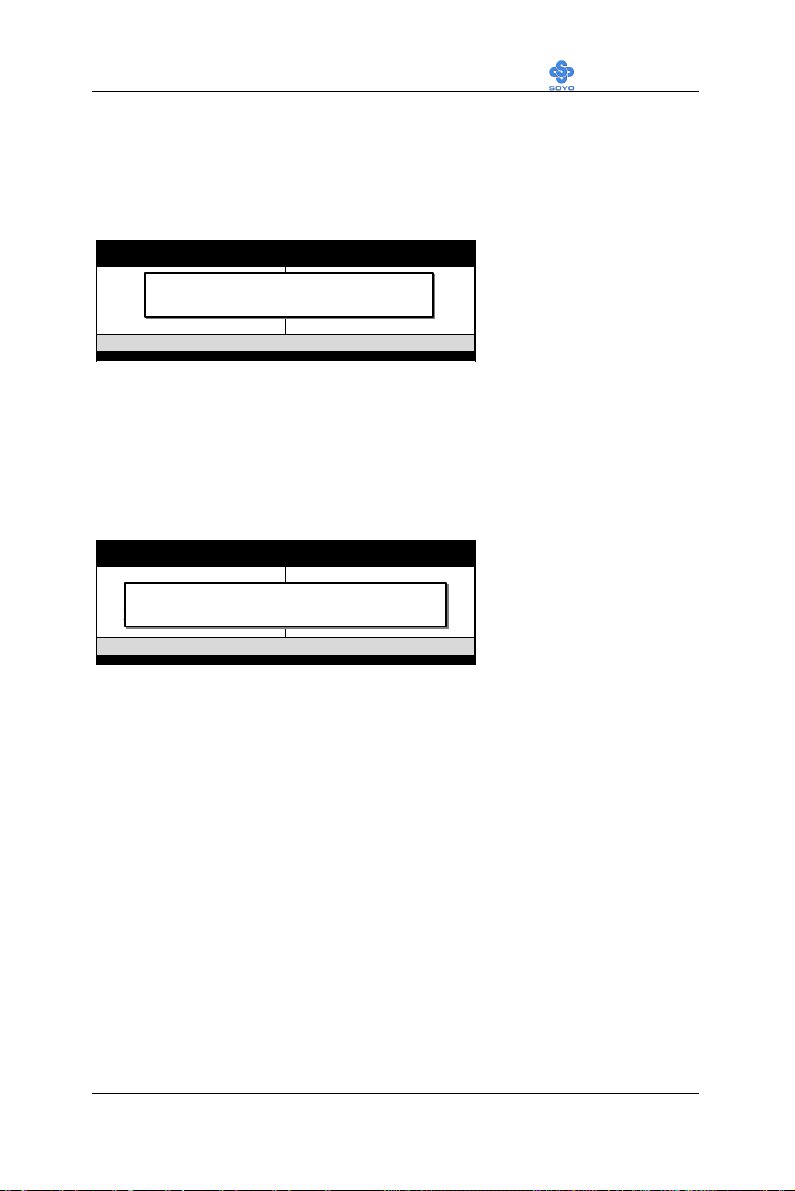
SAVE AND EXIT SETUP
Select the [SAVE & EXIT SETUP] option from the Main Menu to save
data to CMOS and exit the setup utility. This option saves all your changes
and causes the system to reboot.
ROM PCI/ISA BIOS
CMOS SETUP UTILITY
STANDARD CMOS SETUP
BIOS FEATURES SETUP
CHIPSET FEATURES SETUP
POWER MANAGEMENT SETUP
SAVE to CMOS and EXIT
PNP/PCI CONFIGURATION
LOAD SETUP DEFAULTS
LOAD BIOS DEFAULTS
: Quit
: Save & Exit Setup
AWARD SOFTWARE, INC.
Time, Date, Hard Disk Type…
INTEGRATED PERIPHERALS
SUPERVISOR PASSWORD
USER PASSWORD
IDE HDD AUTO DETECTION
SAVE & EXIT SETUP
EXIT WITHOUT SAVING
↑ ↓ → ←
: Select Item
: Change Color
Type [Y] to save the
changes and exit or [N]
to return to the Main
Menu and keep current
values.
EXIT WITHOUT SAVING
Selecting the [EXIT WITHOUT SAVING] option allows you to abandon
all data and exit setup, therefore ignoring all your changes.
ROM PCI/ISA BIOS
CMOS SETUP UTILITY
STANDARD CMOS SETUP
BIOS FEATURES SETUP
CHIPSET FEATURES SETUP
POWER MANAGEMENT SETUP
PNP/PCI CONFIGURATION
LOAD SETUP DEFAULTS
LOAD BIOS DEFAULTS
: Quit
: Save & Exit Setup
AWARD SOFTWARE, INC.
Quit Without Saving (Y/N)? _
Time, Date, Hard Disk Type…
INTEGRATED PERIPHERALS
SUPERVISOR PASSWORD
USER PASSWORD
IDE HDD AUTO DETECTION
SAVE & EXIT SETUP
EXIT WITHOUT SAVING
↑ ↓ → ←
: Select Item
: Change Color
Type [Y] to abandon
changes and exit or [N]
to return to the Main
Menu and keep current
values.
50
Page 55
Motherboard’s BIOS Setup Utility LI-7000
4-1 SOYO COMBO SETUP
This Motherboard does not use any hardware jumpers to set the CPU
frequency. Instead, CPU settings are software configurable with the BIOS
[SOYO COMBO SETUP].
After the hardware installation is complete, turn the power switch on, then
press the <DEL> key during the system diagnostic checks to enter the
Award BIOS Setup program. The CMOS SETUP UTILITY will display
on screen. Then, select the [SOYO COMBO SETUP] option from the
main menu and press the <Enter> key.
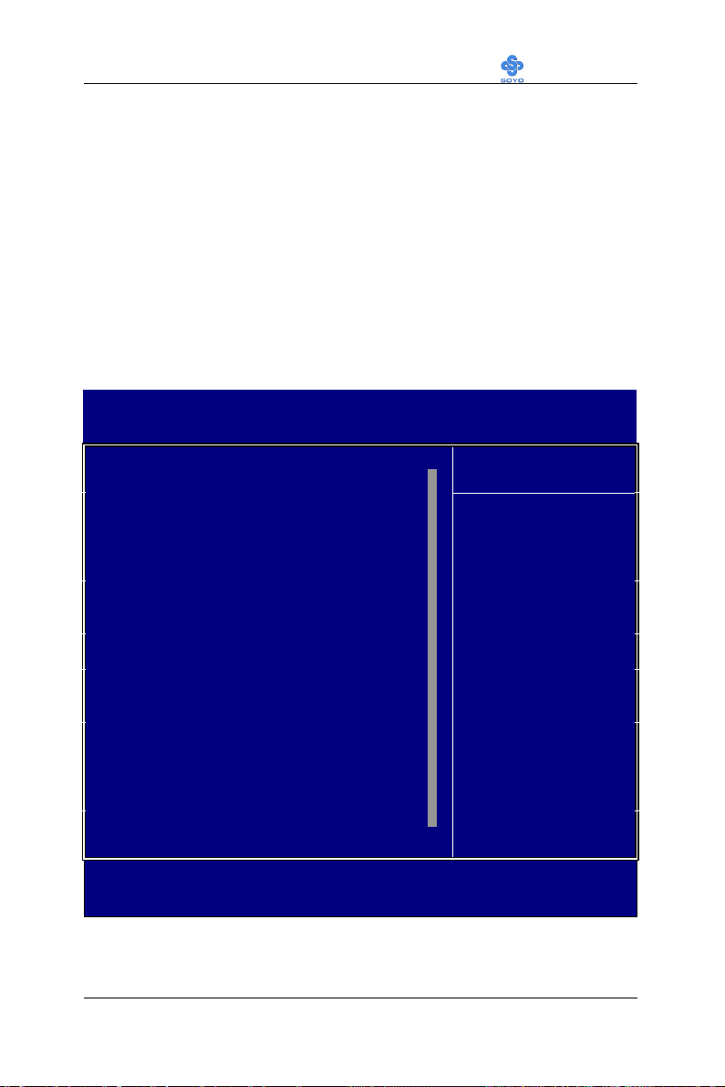
CMOS Setup Utility – Copyright ( C ) 1984-1999 Award Software
Soyo Combo Feature
CPU Clock/ Spread spectrum Default
CPU Ratio X 3
CPU L2 Cache ECC Checking Enabled
Quick Power On Self Test Enabled
SMAA [7:4] / SMAB [7:4] 4x / 4x
First Boot Device Floppy
Second Boot Device HDD-0
Third Boot Device LS/ZIP
Boot Other Device Enabled
AC97 Audio Enabled
AC97 Modem Enabled
POWER ON Function Button Only
x KB Power ON Password Enter
x Hot Key Power ON Ctrl-F1
Soft-Off by PWR-BTTN Instant-Off
Wake-Up by PCI card Disabled
Power On by Ring Enabled
Resume by Alarm Disabled
x Date (of Month) Alarm 0
x Time (hh:mm:ss) Alarm 0
áâàß:Move Enter:Select +/-/PU/PD:Value F10:Save ESC:Exit F1:General Help
F5:Previous Values F6:Fail-Safe Defaults F7: Optimized Defaults
5
Menu Level 4
6
Item Help
The [SOYO COMBO SETUP] menu combines the main parameters that
you need to configure, all in one menu, for a quick setup in BIOS.
51
Page 56
Motherboard’s BIOS Setup Utility LI-7000
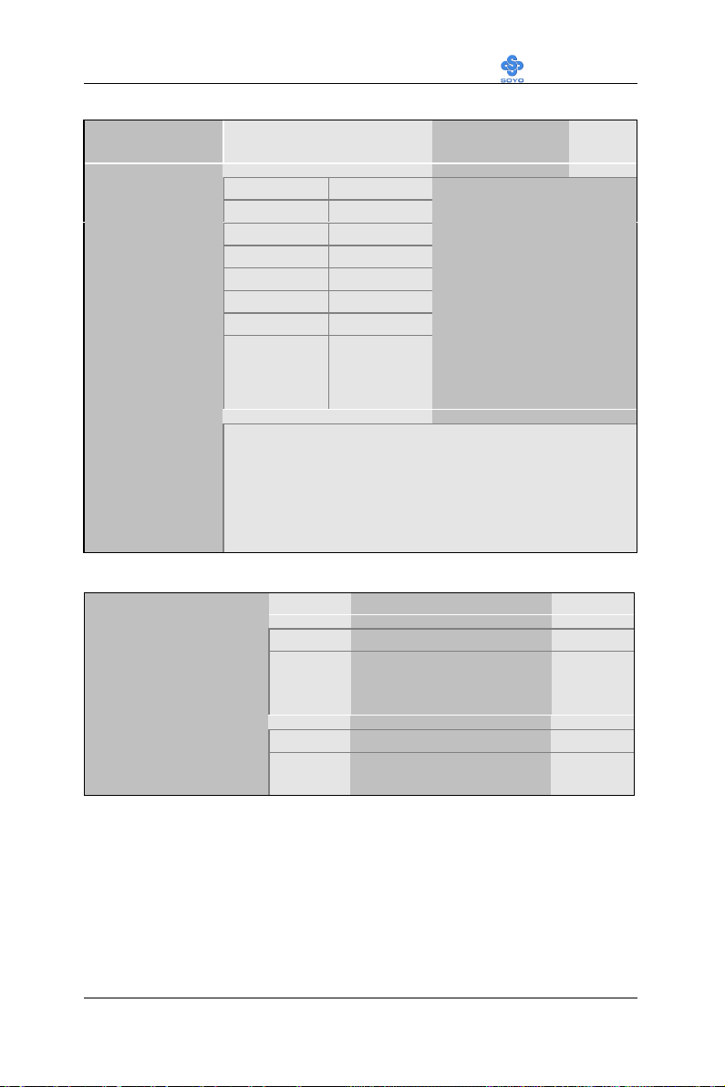
4-1.1 Quick CPU Frequency Setup
Quick CPU
Frequency Setup
Setting Description Note
CPU Clock/
Spread spectrum
CPU Ratio
4-1.2 L2 Cache Memory
CPU L2 Cache ECC
Checking
Default 112 MHz/on
66 MHz/off 117 MHz/on
66 MHz/on 124 MHz/off
75 MHz/off 133 MHz/off
83 MHz/off 133 MHz/on
95 MHz/off 138 MHz/off
100 MHz/off 140 MHz/on
100 MHz/on 150 MHz/off
After you have selected the host clock, choose the right
multiplier for the CPU. Options are: [3., 3.5, 4, 4.5, 5,
5.5,6,6.5,7.0,7.5,8.0]. The CPU frequency is then defined as
[host clock freq.]x[multiplier], and should the working
frequency of your Pentium® III, Pentium® II & Celeron
processor.
Setting Description Note
Disabled
Enabled This option activates the
Select the host clock of your
Socket 370 processor among
these values.
Note: For the 810 chipset,
66 and 100 MHz host
clock frequencies are
acceptable. However, the
system stability is not
guaranteed for other
frequencies due to the
limitations of this chipset.
Default
CPU L2 cache ECC
checking function.
Quick Power On Self
Test
Disabled
Enabled Provides a fast POTS at
boot-up.
52
Default
Page 57
Motherboard’s BIOS Setup Utility LI-7000
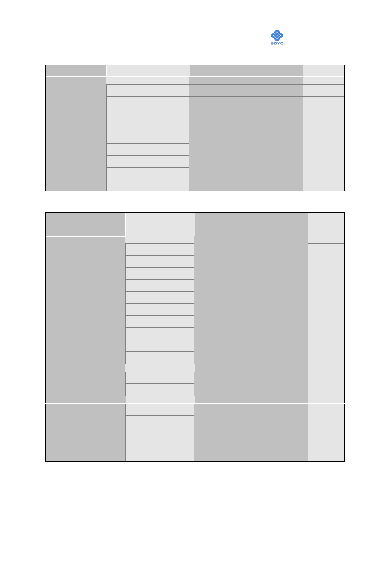
4-1.3 Memory Buffer Strength
Setting Description Note
SMAA [7:4] /
SMAB [7:4]
4-1.4 System Boot Control Settings
System Boot
Control Settings
First
/Second/Third
Boot Device
4x / 4x Default
4x / 4x 2x / 4x
4x / 3x 2x / 3x
4x / 2x 2x / 2x
4x / 1x 2x / 1x
3x / 4x 1x / 4x
3x / 3x 1x / 3x
3x / 2x 1x / 2x
3x / 1x 1x / 1x
Setting Description Note
Floppy
LS/ZIP
HDD-0
SCSI
CDROM
HDD-1
HDD-2
HDD-3
LAN
Disabled
This item sets the strength
of the buffer that drives the
address section of the
memory bus. Change the
setting only if you are an
experienced user.
Select Your Boot Device
Priority
Boot Other
Device
AC97
Audio/Modem
Disabled
Enabled
Disabled
Auto
Select Your Boot Device
Priority
This item allows you to
decide to enable/disable the
810 chipset family to
support AC97 Audio/
Modem.
53
Default
Default
Page 58
Motherboard’s BIOS Setup Utility LI-7000
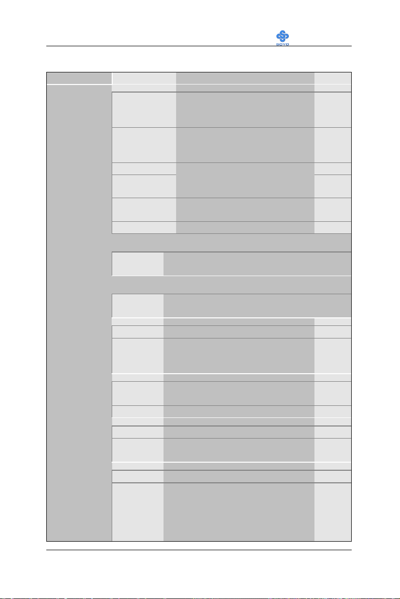
4-1.5 Others Optional
Setting Description Note
POWER ON
Function
If [POWER ON Function] is set to [Password]
KB Power ON
Password
If [POWER ON Function] is set to [Hot Key]
Hot Key Power
ON
Soft-Off by
PWR-BTTN
Wake-Up by
PCI card
Password Enables you to wake-up the
system by entering a password at
the keyboard.
Hot KEY You can wake-up the system by
pressing the key combination of
your choice (Ctrl-F1~F12).
Mouse Left
Mouse Right
BUTTON-ONLY Disables the Wake-Up by
Keyboard 98
Enter (your
password)
CtrlF1~F12
Instant-off Default
Delay 4
Sec.
Disabled If enabled any PCI interrupt will
Enabled
Enables waking up the system by
pressing either the right or left
mouse button.
Keyboard function.
Set the password that will wake-up your
system.
Choose the key combination that will wakeup the system. [Ctrl-F1 to Ctrl-F12]
Turns off the system power 4
seconds after pushing the power
button.
wake up the system.
Default
Default
Power On by
Ring
Resume by
Alarm
Disabled
Enabled The system will self-power on me
when the modem is ringing.
Disabled The system ignores the alarm. Default
Enabled Set alarm to power on the system by
the date (1-31) or time (hh:mm:ss).
If the date is set to [0], the system
will self-power on by alarm
everyday at the set time.
54
Default
Page 59
Motherboard’s BIOS Setup Utility LI-7000
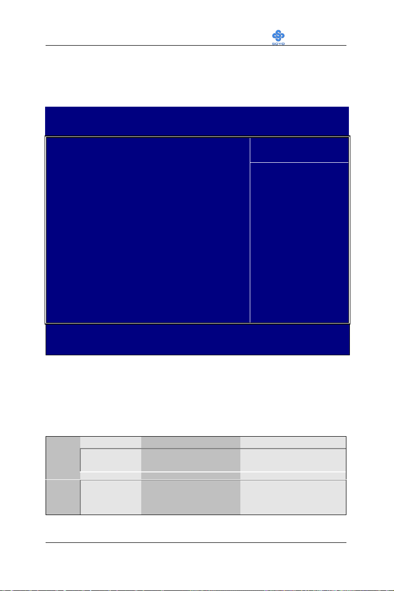
4-2 STANDARD CMOS SETUP
Select the [STANDARD CMOS SETUP] option from the Main Menu and
press [Enter] key.
CMOS Setup Utility – Copyright ( C ) 1984-1999 Award Software
Standard CMOS Features
Date (mm:dd:yy) Fri, Jan 1 1999
Time (hh:mm:ss) 1 : 22 : 12
4 IDE Primary Master Press Enter None
4 IDE Primary Slave Press Enter None
4 IDE Secondary Master Press Enter None
4 IDE Secondary Slave Press Enter None
Drive A 1.44M, 3.5 in.
Drive B None
Floppy 3 Mode Support Disabled
Video EGA/VGA
Halt On All Errors
Base Memory 640K
Extended Memory 30720K
Total Memory 31744K
áâàß:Move Enter:Select +/-/PU/PD:Value F10:Save ESC:Exit F1:General Help
F5:Previous Values F6:Fail-Safe Defaults F7: Optimized Defaults
Menu Level 4
Item Help
This screen allows you to modify the basic CMOS settings.
After you have completed the changes, press [Esc] key to return to the
Main Menu.
4-2.1 Date & Time
Display Setting Please Note
Date
mm/dd/yyyy Type the current date You can also the
PUp/PDn keys to toggle
Time
hh:mm:ss Type the current time 24-hour clock format
3:15 PM is displayed as
15:15:00
55
Page 60
Motherboard’s BIOS Setup Utility LI-7000
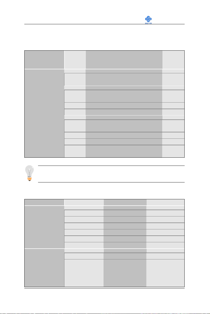
4-2.2 Hard Disks Type & Mode
Choose the type and mode for the hard disks that you have already
installed.
Primary
Setting Description Note
(Secondary)
Master & Slave
IDE HDD AutoDetection
IDE Primary
Slave
(User Type)
Press
Enter
Auto BIOS detects hard disk type
User User defines the type of hard disk.
To auto-detect the HDD’s size,
head… on this channel
automatically.
None
Access Mode
Auto BIOS detects hard disk mode
automatically.
Normal Normal IDE hard disk <528MB
LBA Enhanced IDE hard disk >528MB
Large Large IDE hard disk (for certain
hard disk)
Note: If you have any questions on your hard disk type or mode, ask
your hard disk provider or previous user for details.
4-2.3 Floppy Drives
Floppy Drives Setting Description Note
Drives A & B
360KB, 5.25 in.
1.2MB, 5.25 in.
720KB, 3.5 in.
1.44MB, 3.5 in. Default
2.88MB, 3.5 in.
None Not installed
Default
Default
Floppy 3-Mode
Support
Disabled Default
Drive A
Drive B
Both
Supports 3-mode
floppy diskette:
740KB/1.2MB/
1.44MB on selected
disk drive.
Special disk drive
commonly used in
Japan
56
Page 61
Motherboard’s BIOS Setup Utility LI-7000
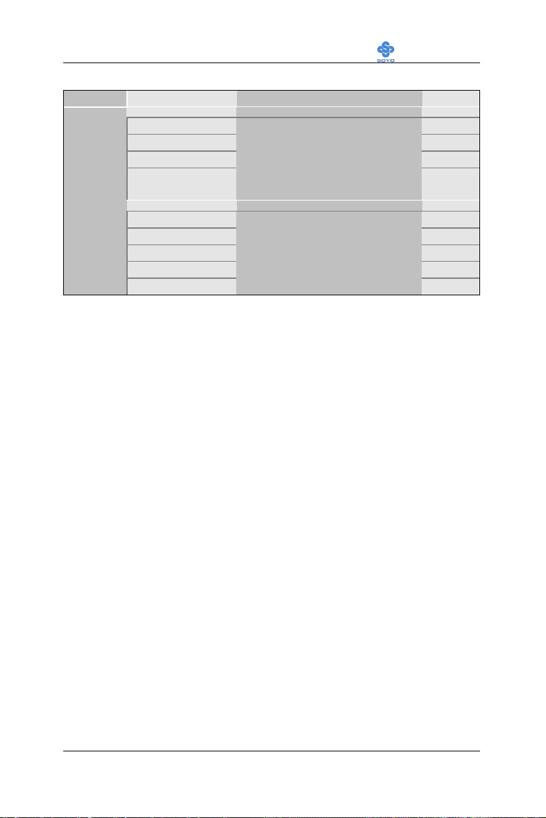
4-2.4 Others Optional
Setting Description Note
Video
Halt On
EGA/VGA Default
CGA 40
CGA 80
MONO
(Monochrome)
ALL Errors Default
No Errors
All, But Keyboard
All, But Diskette
All, But Disk/Key
Select the video mode.
When the BIOS detects system
errors, this function will stop the
system. Select which type of
error will cause the system halt.
57
Page 62

Motherboard’s BIOS Setup Utility LI-7000
4-3 ADVANCED BIOS FEATURES
Select the [Advanced BIOS Features] option from the Main Menu and
press [Enter] key.
CMOS Setup Utility – Copyright ( C ) 1984-1999 Award Software
Advanced BIOS Features
Anti-Virus Protection Enabled
CPU Internal Cache Enabled
External Cache Enabled
Swap Floppy Drive Disabled
Boot Up Floppy Seek Disabled
Boot Up NumLock Status ON
Gate A20 Option Fast
Typematic Rate Setting Disabled
x Typematic Rate (Chars/Sec) 6
x Typematic Delay (Msec) 250
Security Option Setup
OS Select For DRAM > 64MB Non-OS2
Report No FDD For WIN 95 Yes
áâàß:Move Enter:Select +/-/PU/PD:Value F10:Save ESC:Exit F1:General Help
F5:Previous Values F6:Fail-Safe Defaults F7: Optimized Defaults
Menu Level 4
Item Help
After you have completed the changes, press [Esc] key and follow the
instructions on your screen to save your settings or exit without saving.
58
Page 63
Motherboard’s BIOS Setup Utility LI-7000
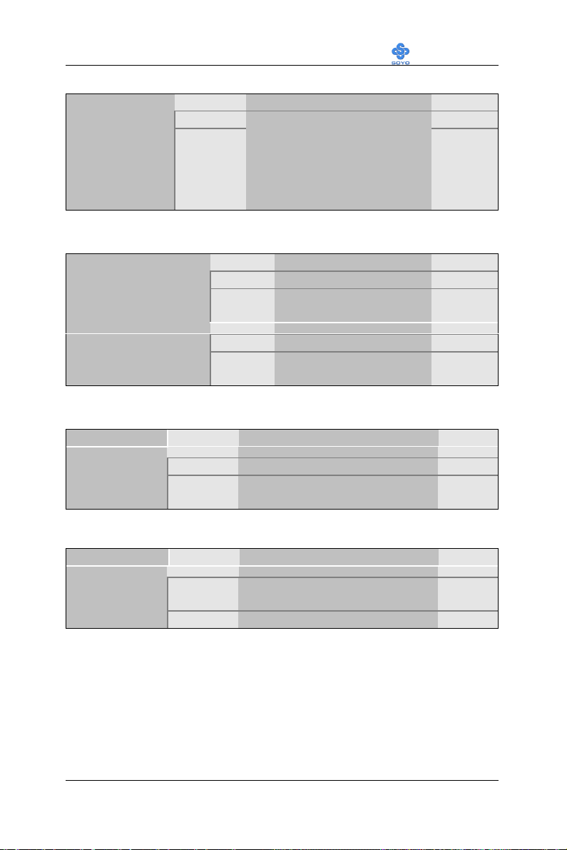
4-3.1 Virus Warning
Setting Description Note
Anti - Virus
Protection
4-3.2 Cache Memory Options
CPU Internal Cache
Disabled
Enabled
If set to enabled, the Paragon
Anti-Virus. Function will scan
your boot drive for boot
virusses. If a boot virus is
detected, the BIOS will display
a warning message.
Setting Description Note
Disabled
Enabled Enables the CPU's internal
cache.
Default
Default
External Cache
4-3.3 Floppy Driver Settings
Swap Floppy
Drive
4-3.4 Boot Up Floppy Seek
Boot Up Floppy
Seek
Disabled
Enabled Enables the external
Setting Description Note
Disabled Default
Enabled Changes the sequence of A and B
drives.
Setting Description Note
Disabled Seeks disk drives during boot up.
Disabling speeds boot up.
Enabled
Default
memory.
Default
59
Page 64
Motherboard’s BIOS Setup Utility LI-7000
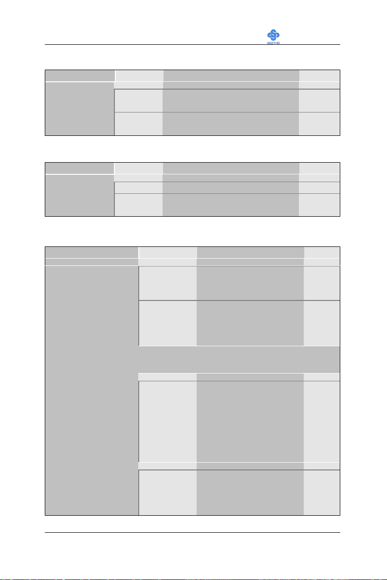
4-3.5 Boot Up NumLock Status
Setting Description Note
Boot Up
NumLock
Status
On Puts numeric keypad in
NumLock mode at boot-up.
Off Puts numeric keypad in arrow key
Default
mode at boot-up.
4-3.6 Gate A20 Options
Setting Description Note
Gate A20
Options
Normal Lets chipset control GateA20.
Fast A pin in the keyboard controller
Default
controls GateA20.
4-3.7 Typematic Settings
Typematic Settings Setting Description Note
Typematic
Rate Setting
Disabled Keystrokes repeat at a rate
determined by the
Default
keyboard.
Enabled When enables , the
typematic rate and
typematic delay can be
selected.
The following [Typematic Rate] and [Typematic Delay] fields are active
only if [Typematic Rate Setting] is set to [Enabled]
Typematic Rate
Typematic Delay
6 (Char/sec)
8 (Char/sec)
10 (Char/sec)
12 (Char/sec)
15 (Char/sec)
20 (Char/sec)
24 (Char/sec)
30 (Char/sec)
250 (msec)
500 (msec)
750 (msec)
1000 (msec)
Choose the rate at which a
character is repeated when
holding down a key.
Choose how long after
you press a key down the
character begins
repeating.
60
Default
Default
Page 65
Motherboard’s BIOS Setup Utility LI-7000
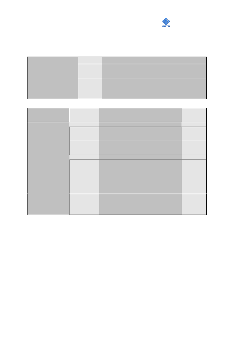
4-3.8 Security Option
Use this feature to prevent unauthorized system boot-up or use of BIOS
Setup. The following table describes the security settings.
Setting Description
Security Option
Other Control Options
Other Control
Options
System Each time the system is booted, the
password prompt appears.
Setup If a password is set, the password prompt
only appears when you attempt to enter the
BIOS Setup program.
Setting Description Note
OS Select for
DRAM>64MB
Report No FDD
For WIN 95
OS2 When using an OS2 operating
system.
Non-OS2 When using another,
non-OS2 operating system.
Yes Windows will release IRQ line 6
(normally used by the Floppy
Disk Drive) after you disable
your on-board FDD and set this
field to [Yes].
No Windows will reserve INT 6 for
your FDD, whether it is disabled
or not.
Default
Default
61
Page 66

Motherboard’s BIOS Setup Utility LI-7000
4-4 ADVANCED CHIPSET FEATURES
Caution: Change these settings only if you are already familiar
with the Chipset.
The [Advanced Chipset Features] option changes the values of the chipset
registers. These registers control the system options in the computer.
CMOS Setup Utility – Copyright ( C ) 1984-1999 Award Software
Advanced Chipset Features
SDRAM CAS Latency Time 3
SDRAM Cycle Time Tras/Trc 6/8
SDRAM RAS-to-CAS Delay 3
SDRAM RAS Precharge Time 3
System BIOS Cacheable Disabled
Video BIOS Cacheable Disabled
Memory Hole AT 15M- 16M Disabled
Delayed Transaction Enabled
Local Memory Frequency 100MHz
áâàß:Move Enter:Select +/-/PU/PD:Value F10:Save ESC:Exit F1:General Help
F5:Previous Values F6:Fail-Safe Defaults F7: Optimized Defaults
Menu Level 4
Item Help
After you have completed the changes, press [Esc] and follow the
instructions on your screen to save your settings or exit without saving.
The following table describes each field in the Advanced Chipset Features
Menu and how to configure each parameter.
62
Page 67
Motherboard’s BIOS Setup Utility LI-7000
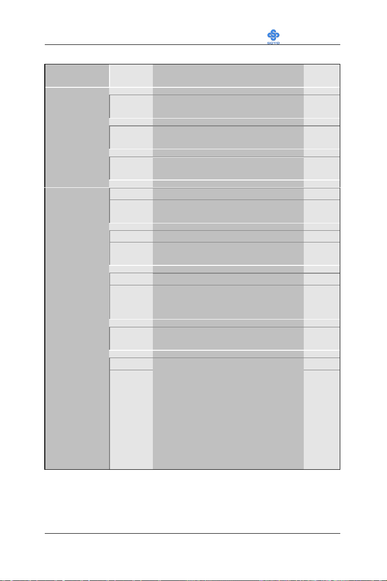
CHIPSET FEATURES SETUP
CHIPSET
Setting Description Note
FEATURES
SDRAM CAS
Latency Time
SDRAM Cycle
Time Tras/Trc
SDRAM RAS-
to-CAS Delay
System BIOS
Cacheable
Video BIOS
Cacheable
Memory Hole
At 15M-16M
Delayed
Transaction
Local Memory
Frequency
2
Use the default setting
3
5/7
6/8
3
2
Use the default setting
Use the default setting
Default
Default
Default
Disabled
Enabled The ROM area F0000H-FFFFFH is
Default
cacheable.
Disabled
Enabled The video BIOS C0000H-C7FFFH is
Default
cacheable.
Disabled Default
Enabled Some interface cards will map their
ROM address to this area. If this
occurs, select [Enabled] in this field.
Enabled Use the default setting Default
100MHz Default
133MHz
This item allows the user to set the
frequency the memory runs at. If this item
is set to 100MHz, make sure to use PC100 compliant DIMM modules. If this
item is set to 133Mhz, PC-133 compliant
modules have to be used. Setting this item
to a higher frequency than is supported by
your SDRAM DIMM modules may lead
to system crashes.
Note: Only the 810E chipset supports
this Feature.
63
Page 68
Motherboard’s BIOS Setup Utility LI-7000
4-5 INTEGRATED PERIPHERALS
Caution: Change these settings only if you are already familiar
with the Chipset.
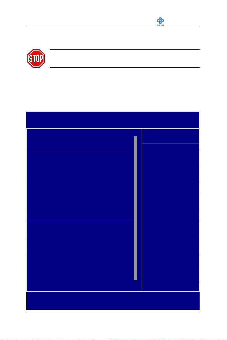
The [INTEGRATED PERIPHERALS] option changes the values of the
chipset registers. These registers control the system options in the
computer.
The following screen shows setup default settings.
CMOS Setup Utility – Copyright ( C ) 1984-1999 Award Software
Integrated Peripherals
On-Chip Primary PCI IDE Enabled
On-Chip Secondary PCI IDE Enabled
IDE Primary Master PIO Auto
IDE Primary Slave PIO Auto
IDE Secondary Master PIO Auto
IDE Secondary Slave PIO Auto
IDE Primary Master UDMA Auto
IDE Primary Slave UDMA Auto
IDE Secondary Master UDMA Auto
IDE Secondary Slave UDMA Auto
USB Controller Enabled
USB Keyboard Support Disabled
Init Display First PCI Slot
IDE HDD Block Mode Enabled
Onboard FDC Controller Enabled
Onboard Serial Port 1 3F8/IRQ4
Onboard Serial Port 2 2F8/IRQ3
UART Mode Select Normal
x RxD , TxD Active Hi, Lo
x IR Transmittiion delay Enabled
Onboard Parallel Port 378/IRQ7
Parallel Port Mode SPP
x EPP Mode Select EPP1.7
x ECP Mode Use DMA 3
PWRON After PWR-Fail Off
Game Port Address 201
Midi Port Address Disabled
x Midi Port IRQ 5
áâàß:Move Enter:Select +/-/PU/PD:Value F10:Save ESC:Exit F1:General Help
F5:Previous Values F6:Fail-Safe Defaults F7: Optimized Defaults
5
Menu Level 4
6
Item Help
64
Page 69
Motherboard’s BIOS Setup Utility LI-7000
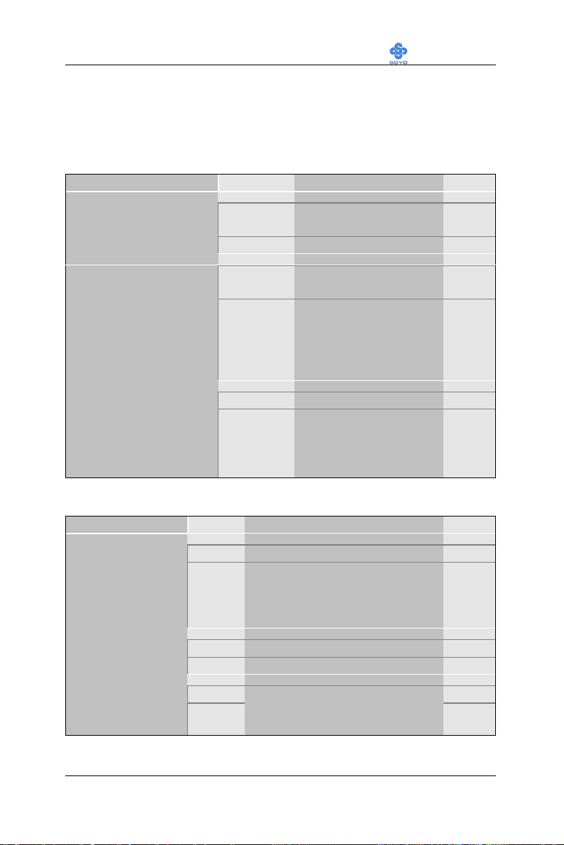
The following tables describe each field in the INTEGRATED
PERIPHERALS Menu and provide instructions on how to configure the
IDE controls, FDC controls, and the onboard serial and parallel ports.
4-5.1 IDE Device Controls
IDE Controls Setting Description Note
On-Chip PCI IDE
Ø Primary
Ø Secondary
IDE
Ø Primary Master PIO
Ø Primary Slave PIO
Ø Secondary Master PIO
Ø Secondary Slave PIO
Disabled Turn off the on-board
IDE
Enabled Use the on-board IDE Default
mode 0-4 0 is the slowest speed
4 is the fastest speed
Auto For better performance
Default
and stability, we suggest
you use the Auto setting
to set the HDD control
timing.
IDE
Ø Primary Master UDMA
Ø Primary Slave UDMA
Ø Secondary Master UDMA
Ø Secondary Slave UDMA
Disabled
Auto Select Auto to enable
Ultra DMA Mode
support.
Default
4-5.2 Keyboard Controls
Keyboard Controls Setting Description Note
USB Controller
Disabled
Enabled Select Enabled if your system
Default
contains a Universal Serial Bus
(USB) controller and you have
USB peripherals.
USB Keyboard
Support
Init Display First
Disabled Turn off the on-board IDE Default
Enabled Use a USB keyboard
PCI Slot Default
AGP
Choose which card – AGP
Display card or PCI VGA card –
to initialize first.
65
Page 70
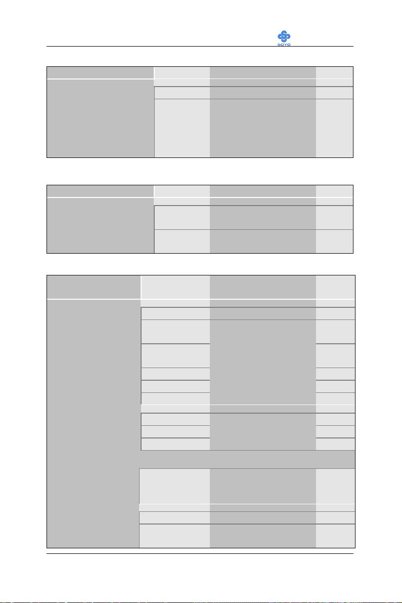
Motherboard’s BIOS Setup Utility LI-7000
4-5.3 IDE HDD Block Mode
Setting Description Note
IDE HDD Block Mode
4-5.4 FDC Controls
FDC Controls Setting Description Note
Onboard FDC
controller
4-5.5 Onboard Serial Ports
Onboard Serial
Ports
Onboard
Serial Port 1 / Serial
Port 2
Disabled
Enabled Invokes multi-sector
transfer instead of one
sector per transfer. Not
all HDDs support this
function.
Disabled Turn off the on-board
floppy controller
Enabled Use the on-board floppy
controller
Setting Description Note
Disabled
3F8/IRQ4 Default
2F8/IRQ3 Default
3E8/IRQ4
2E8/IRQ3
Auto
Choose serial port 1 &
2's I/O address.
Do not set port 1 & 2 to
the same address except
for Disabled or Auto.
Default
Default
(port 1)
(port 2)
UART Mode Select
If [UART Mode Select] is set to [IrDA]/[ASKIR]
RxD, TxD Active
IR Transmittiion
delay
Normal Default
IrDA
ASKIR
Hi, Hi, Lo, Lo,
Lo, Hi, Hi, Lo
Disabled
Enabled Some IR devices need
The second serial port
offers these InfraRed
interface modes.
This item allows you to
determine the active of
RxD, TxD.
this item enabled.
66
Default
Page 71
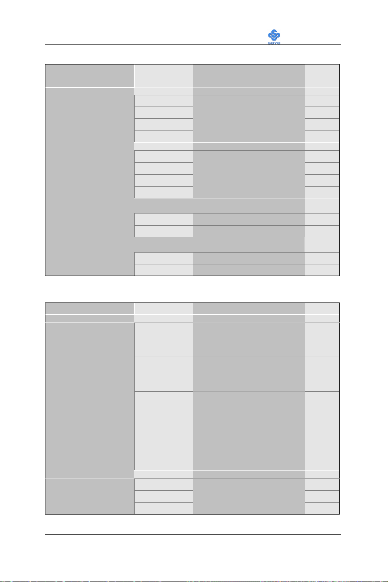
Motherboard’s BIOS Setup Utility LI-7000
If [Parallel Port Mode] is set to [ECP] mode
If [Parallel Port Mode] is set to [EPP] mode
4-5.6 Onboard Parallel Ports
Onboard Parallel
Setting Description Note
Ports
Onboard Parallel
Port
Disabled
378/IRQ7 Default
3BC/IRQ7
278/IRQ5
Parallel Port Mode
SPP Default
EPP
ECP
ECP+EPP
ECP Mode use
DMA
EPP Mode Select
EPP 1.9 Select EPP port type 1.9
EPP 1.7 Select EPP port type 1.7 Default
4-5.7 Others Optional
Setting Description Note
PWRON After
On The system will switch on
PWR-Fail
Off The system will remain off
Former-Sts The system will return to
Choose the printer I/O
address.
The mode depends on your
external device that
connects to this port.
3 Choose DMA3 Default
1 Choose DMA1
when power comes back
after a power failure.
Default
when power comes back
after a power failure.
the state it was in before the
power failure when power
returns. (i.e: If the system
was on, it will switch on
again, if it was off, it will
remain off)
Game Port Address
Disabled
201 Default
209
Set the I/O base address for
the ON board game port
under this item.
67
Page 72
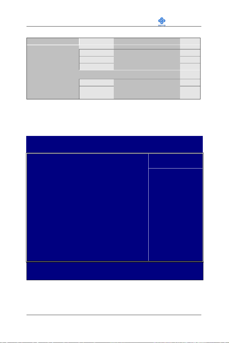
Motherboard’s BIOS Setup Utility LI-7000
If [Midi Port Address] is set to [330]/[300] mode
Others Optional
Setting Description Note
Midi Port Address
Disabled Default
330
Set the I/O address for the
on board Midi port here.
300
Midi Port IRQ
5
10
Select the IRQ that the
Midi port uses under this
Default
them.
4-6 POWER MANAGEMENT SETUP
The [POWER MANAGEMENT SETUP] sets the system's power saving
functions.
CMOS Setup Utility – Copyright ( C ) 1984-1999 Award Software
Power Management Setup
ACPI Function Enabled
xACPI Suspend Type S1 (POS)
Power Management User Define
Video Off Method DPMS
Video Off In Suspend Yes
Suspend Type Stop Grant
MODEM Use IRQ 3
Suspend Mode Disabled
HDD Power Down Disabled
Cpu Thermal-Throttling 62.5%
Menu Level 4
Item Help
** Reload Global Timer Events **
Primary IDE 0 Disabled
Primary IDE 1 Disabled
Secondary IDE 0 Disabled
Secondary IDE1 Disabled
FDD,COM, LPT Port Disabled
PCI PIRQ[A-D]# Disabled
áâàß:Move Enter:Select +/-/PU/PD:Value F10:Save ESC:Exit F1:General Help
F5:Previous Values F6:Fail-Safe Defaults F7: Optimized Defaults
After you have completed the Power Management Setup, press [Esc] to
return to the Main Menu.
68
Page 73
Motherboard’s BIOS Setup Utility LI-7000
4-6.1 Power Management Controls
Power
Management
Controls
Setting Description Note
ACPI function
ACPI Suspend
Type
Power
Management
Video Off
Method
Video Off In
Suspend
Suspend Type
Disabled
Enabled ACPI (Advanced
Configuration Power
Management Interface)
S1 (POS) The system will enter the S1
state during suspend. (Low
latency wake up)
User Define Lets you define the HDD and
system power down times.
Doze
timer
Min Saving 1 Hour 1 Hour 1 Hour 15 Min
Max Saving 1 Min 1 Min 1 Min 1 Min
V/H
Sync+Blank
Blank screen
DPMS
Yes Default
No
Stop Grant The system can wake up
PwrOn
Suspend
Selects the method by which
the monitor is blanked.
This determines the manner in
which the monitor is blanked.
through external events.
The system can only wake up
through the Power-Button.
Standby
timer
Suspend
timer
Default
Default
HDD
power
down
Default
Default
MODEM Use
IRQ
Standby Mode
3 Default
3-11, NA
Disable Default
1Min-1Hour When the set time has elapsed,
Assigns an IRQ# to the modem
device.
BIOS sends a command to the
system to enter Standby Mode.
69
Page 74
Motherboard’s BIOS Setup Utility LI-7000
Power Management Controls (Continued)
Power
Setting Description Note
Management
Controls
HDD Power
Down
Disabled Default
1-15Min When the set time has
elapsed, BIOS sends a
command to the HDD to
power down. This turns off
the HDD motor.
CPU ThermalThrottling
87.5%
75.0%
62.5% Default
50.0%
37.5%
This item sets the proportion
of the original clock
frequency to which the CPU
will slow do in suspend
mode.
25.0%
4-6.2 Reload Global Timer Events
Power Down
Setting Description Note
& Resume
Events
IDE0, IDE1
Ø Primary
Ø Secondary
FDD, COM,
LPT Port
Disabled Default
Enabled Enables the PM timers when [No
Activity Event] is detected.
Disabled Default
Enabled Enables the PM timers when [No
Activity Event] is detected.
Some older model
HDDs may not
support this
advanced function.
PCI PIRQ [AD]#
Disabled
Enabled The system monitors these
elements for activity. The system
will resume if [IRQ activity] is
detected.
70
Default
Page 75
Motherboard’s BIOS Setup Utility LI-7000
4-7 PNP/PCI CONFIGURATION SETUP
This option sets the Motherboard's PCI Slots.
CMOS Setup Utility – Copyright ( C ) 1984-1999 Award Software
PnP/PCI Configurations
PNP OS Installed No
Reset Configuration Data Disabled
Resources Controlled By Auto (ESCD)
x IRQ Resources Press Enter
PCI/VGA Palette Snoop Disabled
Assign IRQ For USB Enabled
Slot1 IRQ Assignment Auto
áâàß:Move Enter:Select +/-/PU/PD:Value F10:Save ESC:Exit F1:General Help
F5:Previous Values F6:Fail-Safe Defaults F7: Optimized Defaults
Menu Level 4
Item Help
Note: Starred (*) items will disappear when the [Resources
Controlled By] option is set to [Auto].
After you have completed the PCI Slot Configuration, press [Esc] and
follow the instructions on your screen to save your settings or exit without
saving.
71
Page 76
Motherboard’s BIOS Setup Utility LI-7000
4-7.1 PNP/PCI Configuration Controls
PNP/PCI
Setting Description Note
Controls
PnP OS
Installed
Yes Set this field to [Yes] if you
are running Windows 95,
which is PnP compatible.
Reset
Configuration
Data
No If the OS you are running
does not support PnP
configuration.
Disabled Retain PnP configuration
data in BIOS.
Enabled Reset PnP configuration data
Default
(If there is any
doubt, set this
field to [No])
Default
in BIOS.
Resources
Controlled By
Manual BIOS does not manage PCI/ISA PnP
card IRQ assignment.
Requires to assign IRQ-# and DMA-# to PCI or
ISA PnP manually.
IRQ-3,4,5,7,9,10,11,12,14,15 assigned to: _
DMA-0,1,3,5,6,7 assigned to: _
Auto
(ESCO)
The Plug-and-Play BIOS
auto manages PCI/ISA PnP
Recommended
card IRQ assignment
automatically.
If [Resources Controlled By] is set to [Manual]
IRQ-# and
DMA-#
assigned to:
PCI/ISA PnP Choose IRQ-# and
DMA-# assigned to
PCI/ISA PnP card.
Legacy ISA Choose IRQ-# and
DMA-# assigned to
Legacy ISA card.
Under this item the user can assign an IRQ to a PCI slot. However, there under
some conditions the IRQ will not be assigned as selected under this item:
1. IRQs 0, 1, 2, 6, 8, 13 can NOT be assigned, because they are fixed.
2. IRQs 5, 9, 10, 11 are available
3. IRQs 3,4,7,12,14 and 15 will only be assigned if they are free. See the table
below on how to free them:
IRQ-3,4,5,7,9,10,
11,12,14,15
DMA-0,1,3,5,6,7
IRQ-3,4,5,7,9,10,
11,12,14,15
DMA-0,1,3,5,6,7
72
Page 77
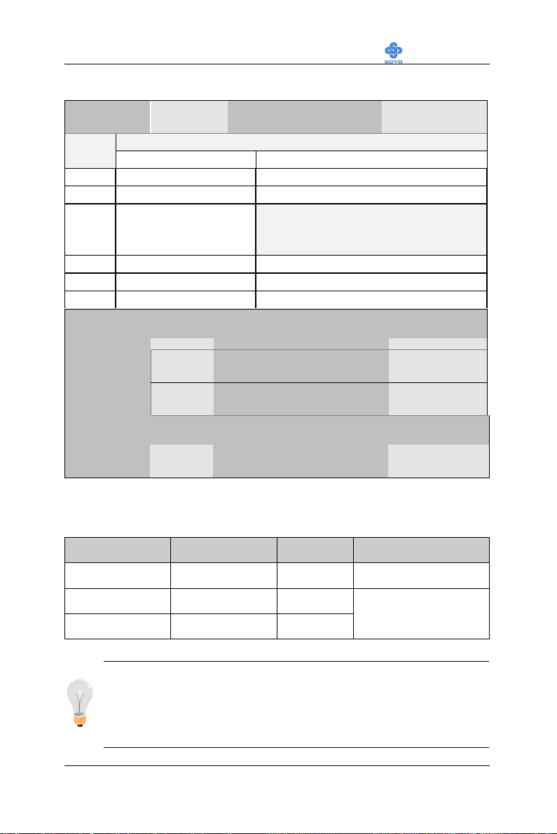
Motherboard’s BIOS Setup Utility LI-7000
PNP/PCI Configuration Setup (Continued)
PNP/PCI
Setting Description Note
Setup
Interrupt
Line
IRQ 15 IRQ 15: PCI / ISA PnP On-Chip Secondary PCI IDE: disabled
IRQ 14 IRQ 14: PCI / ISA PnP On-Chip Primary PCI IDE: disabled
IRQ 12 IRQ 12: PCI / ISA PnP
IRQ 7 IRQ 7: PCI / ISA PnP Onboard parallel port: disabled
IRQ 4 IRQ 4: PCI / ISA PnP Onboard Serial port 1: disabled
IRQ 3 IRQ 3: PCI / ISA PnP Onboard Serial port 2: disabled
4. Your OS may reassign another interrupt to a PCI slot after BIOS passes control
How to set the BIOS to release the IRQ to the PnP Interrupt pool:
PnP / PCI configuration Integrated Peripherals
Interrupt 12 will be released by the PnP
BIOS automatically if the PS/2 Mouse Port
is not used.
to the OS, especially if you use Windows 95, 98 or NT.
Assign IRQ
For USB
Disabled BIOS will assgin IRQ for
USB port.
Enabled BIOS won’t assign IRQ for
Default
USB port.
5. Your OS may reassign another interrupt to a PCI slot after BIOS passes control
to the OS, especially if you use Windows 95, 98 or NT.
Auto DefaultSlot 1 Use
IRQ NO.
Set to Auto the BIOS will
using IRQs Automatically.
4-7.2 MULTI I/O ADDRESSES
Default settings for multi-I/O addresses are as follows:
Port I/O Address IRQ Status
LPT1
COM1
COM2
378H 7 ECP/EPP
3F8H 4
2F8H 3
Warning: If a default I/O address conflicts with other I/O cards
such as sound card, you must change one of the I/O addresses to
remedy to this address conflict. (I/O addresses can be adjusted from
the BIOS Setup Utility)
73
Page 78
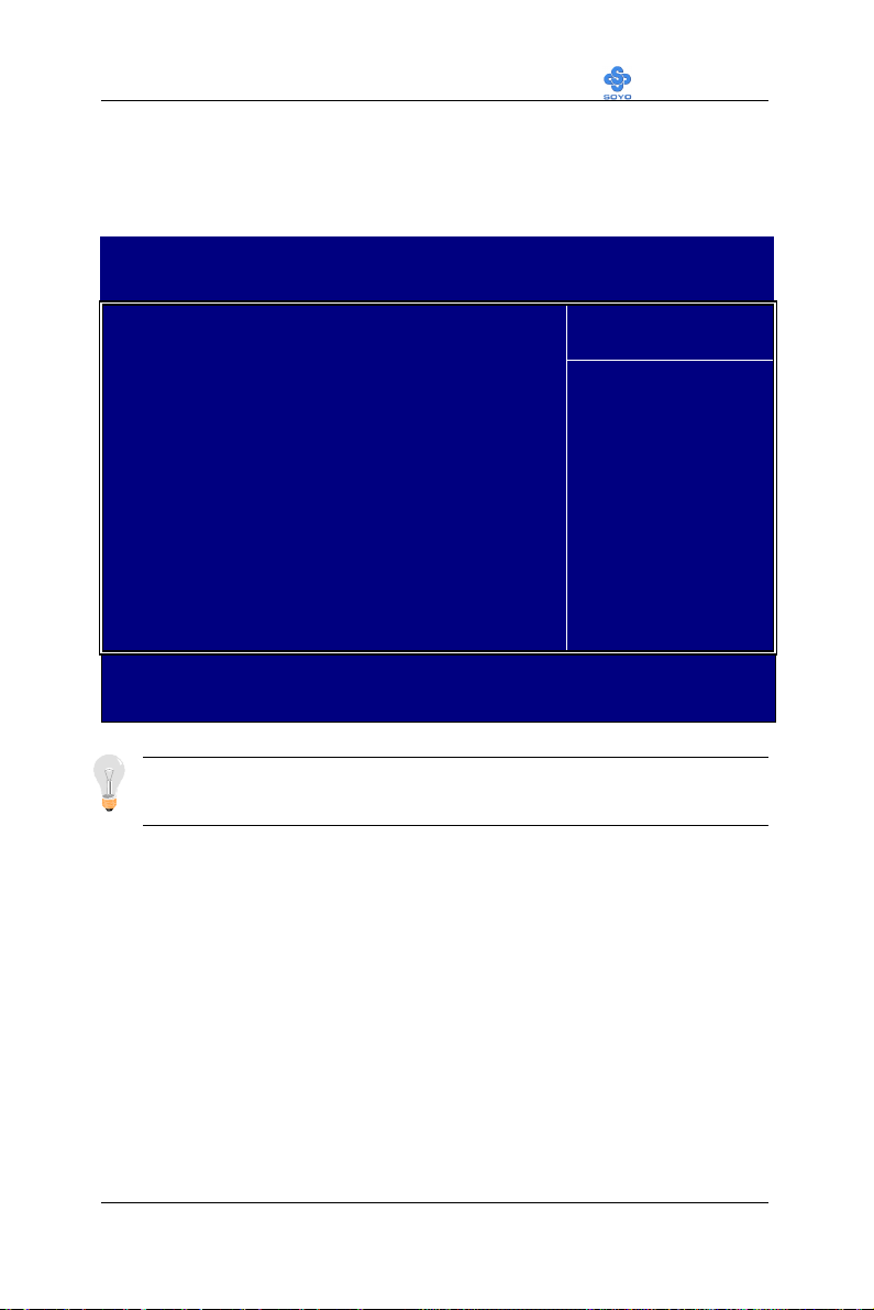
Motherboard’s BIOS Setup Utility LI-7000
4-8 PC HEALTH STATUS
This option sets the Motherboard's PC Health Status.
CMOS Setup Utility – Copyright ( C ) 1984-1999 Award Software
PC Health Status
CPU Warning Temperature Disabled
Current System Temp. 25 º C / 77 º F
Current CPU Dio Temperature 40 º C / 104 º F
Current CPUFAN Speed 5192 RPM
Vcore 2.04 V
VTT 1.50 V
3.3V 3.31 V
+ 5V 5.02 V
+12V 12.03 V
VBAT (V) 3.07 V
5VSB (V) 5.45 V
áâàß:Move Enter:Select +/-/PU/PD:Value F10:Save ESC:Exit F1:General Help
F5:Previous Values F6:Fail-Safe Defaults F7: Optimized Defaults
Menu Level 4
Item Help
Note: Starred (*) items will disappear when the [Resources
Controlled By] option is set to [Auto].
74
Page 79
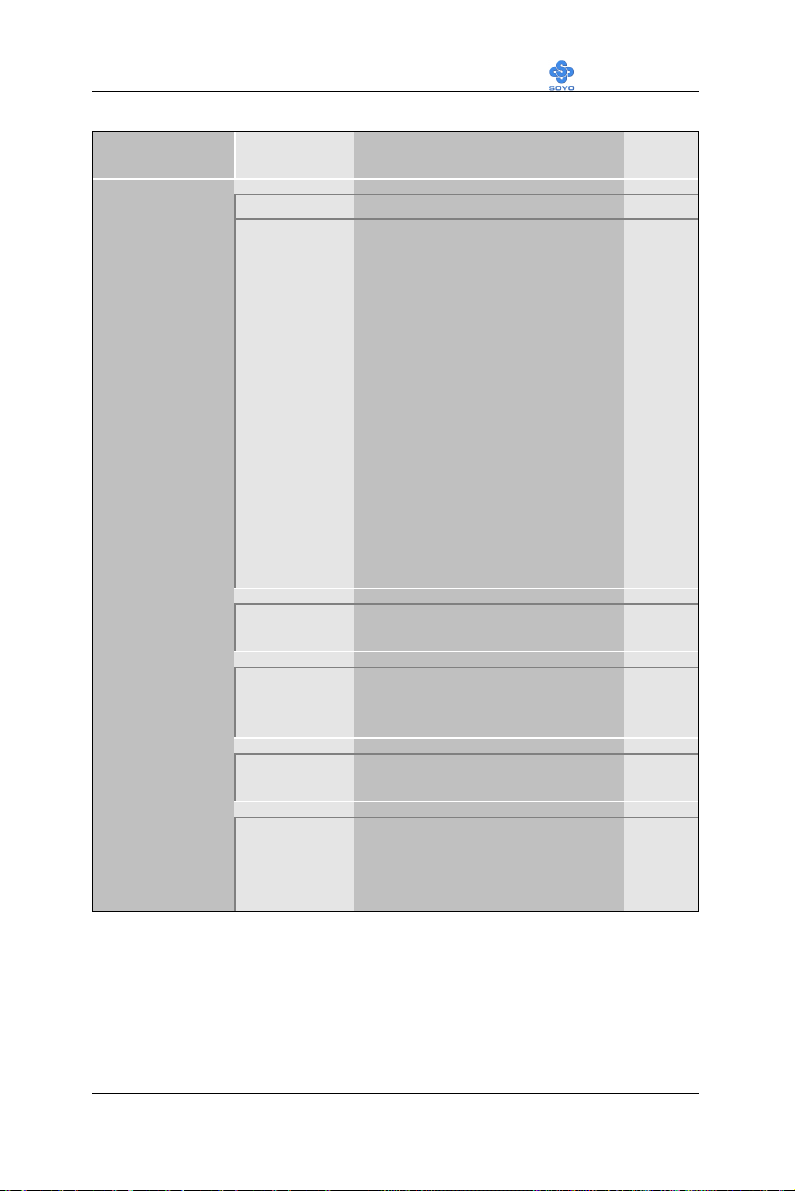
Motherboard’s BIOS Setup Utility LI-7000
4-8.1 CPU Device Monitoring
CPU Device
Monitoring
Setting Description Note
CPU Warning
Temperature
Current System
Temp.
Current CPU
Dio
Temperature
Current
CPUFAN Speed
Disabled Default
50°C/122°F
53°C/127°F
56°C/132°F
60°C/140°F
63°C/145°F
66°C/150°F
70°C/158°F
75°C/167°F
80°C/176°F
85°C/185°F
90°C/194°F
95°C/203°F
100°C/212°F
110°C/230°F
120°C/248°F
°C/°F
°C/°F
°C/°F
Set CPU temperature from 50°C
to 70°C. The CPU will slow
down when CPU temperature
goes beyond the preset value.
The CPU will continue to run
slow until the temperature
returns back within the safe
range.
Show the current status of the
system temperature.
Show the current status of CPU
temperature.
Show the current status of CPU
Fan
Vcore, VTT,
3.3V, +5V,
+12V, VBAT,
5VSB
Show the current voltage status.
V
75
Page 80
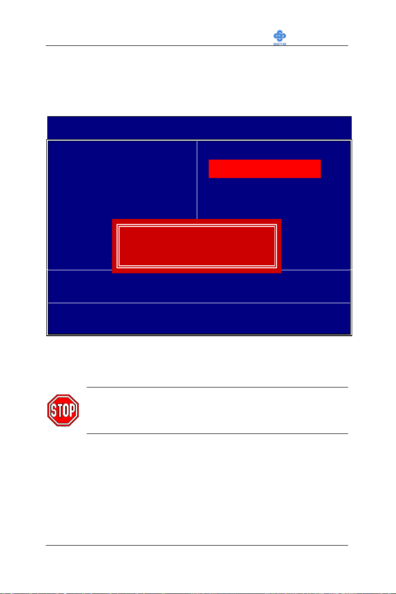
Motherboard’s BIOS Setup Utility LI-7000
4-9 LOAD OPTIMIZED DEFAULTS
Select the [Load Optimized Defaults] option from the Main Menu to load
the system values you have previously saved. This option is recommended
if you need to reset the system setup and to retrieve the old values.
CMOS Setup Utility – Copyright ( C ) 1984-1999 Award Software
4Soyo Combo Feature 4PC Health Status
4Standard CMOS Features Load Optimized Defaults
4Advanced BIOS Features Load Fail - Safe Defaults
4Advanced Chipset Features Set Supervisor Password
4Integrated Peripherals Set User Password
4Power Management Setup Save & Exit Setup
4PnP/PCI Configurations Exit Without Saving
Esc : Quit áâàß : Select Item
F10 : Save & Exit Setup
Load Optimized Defaults (Y/N)? Y
Change CPU’s Clock & Voltage
Type [Y] to use the Setup Defaults followed by [Enter] or otherwise [N] to
return to the Main Menu and keep current values.
Warning: If you run into any problem after changing the BIOS
configuration, please load the SETUP DEFAULTS for stable
performance.
76
Page 81
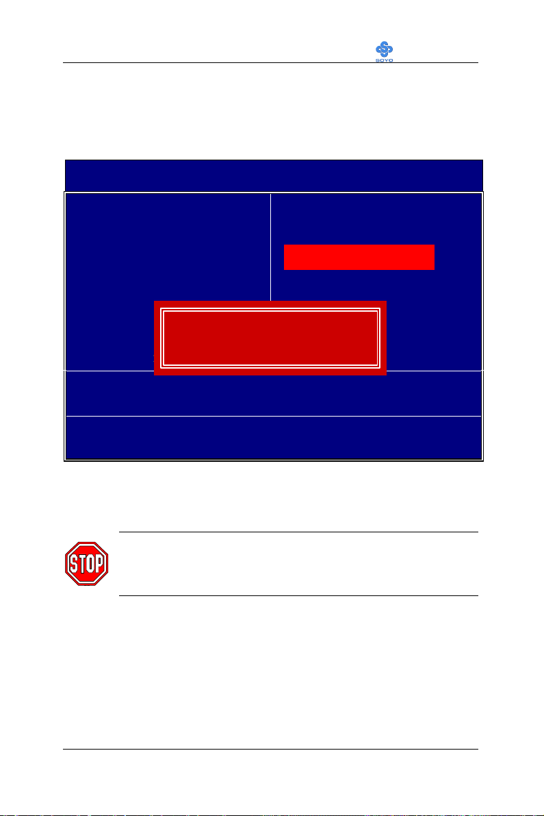
Motherboard’s BIOS Setup Utility LI-7000
4-10 LOAD FAIL-SAFE DEFAULTS
Select the [Load Fail-Safe Defaults] option from the Main Menu to load
the system values you have previously saved. This option is recommended
if you need to reset the system setup and to retrieve the old values.
CMOS Setup Utility – Copyright ( C ) 1984-1999 Award Software
4Soyo Combo Feature 4PC Health Status
4Standard CMOS Features Load Optimized Defaults
4Advanced BIOS Features Load Fail - Safe Defaults
4Advanced Chipset Features Set Supervisor Password
4Integrated Peripherals Set User Password
4Power Management Setup Save & Exit Setup
4PnP/PCI Configurations Exit Without Saving
Esc : Quit áâàß : Select Item
F10 : Save & Exit Setup
Load Fail - Safe Defaults (Y/N)? Y
Change CPU’s Clock & Voltage
Type [Y] to use the Setup Defaults followed by [Enter] or otherwise [N] to
return to the Main Menu and keep current values.
Warning: If you run into any problem after changing the BIOS
configuration, please load the SETUP DEFAULTS for stable
performance.
77
Page 82
Motherboard’s BIOS Setup Utility LI-7000
4-11 SUPERVISOR PASSWORD
Based on the setting you have made in the [Security Option] of the [BIOS
FEATURES SETUP] section, the password prevents access to the system
or the setup program by unauthorized users. Follow this procedure to set a
new password or disable the password:
1. Choose [BIOS FEATURES SETUP] in the Main Menu and press
[Enter]. Select the [Security Options] item and set the field to:
a. [System]: The password is required every time the system is
booted. This means only a person who knows the password can
use this computer.
b. [Setup]: The password is required only when you attempt to
enter the BIOS Setup program.
2. Choose [SUPERVISOR PASSWORD] from the Main Menu and
press [Enter]. The following prompt appear:
Enter Password:
Warning: If you forget or lose the password, the only way to
access the system is to set jumper JP5 to clear the CMOS RAM.
All setup information is lost and you must run the BIOS setup
program again.
Note: If you do not wish to use the password function, press
[Enter] directly and the following message appears:
Password Disabled!!
78
Page 83
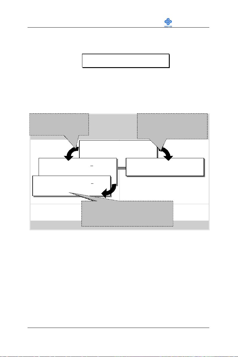
Motherboard’s BIOS Setup Utility LI-7000
F10
(Shift) F2
↔
Type the Password
Press:
password, press
to exit
Type the Password
Press <Enter> without
After you confirm the password,
3. Enter your new password and press [Enter]. The following message
appears, prompting to confirm the new password:
Confirm Password:
4. Re-enter your password and then press [Enter] to exit to the Main
Menu.
This diagram outlines the password selection procedure:
and Press: <Enter>
↔
STANDARD CMOS SETUP
BIOS FEATURES SETUP
CHIPSET FEATURES SETUP
Enter Password:
POWER MANAGEMENT SETUP
PNP/PCI CONFIGURATION
Confirm Password:
LOAD SETUP DEFAULTS
LOAD BIOS DEFAULTS
Esc
: Quit
: Save & Exit Setup
CMOS SETUP UTILITY
AWARD SOFTWARE, INC.
Enter Password:
∗∗∗∗∗
∗∗∗∗∗
After you confirm the
press <Esc> to exit
Time, Date, Hard Disk Type…
ROM PCI/ISA BIOS
Press:
entering the password
Without entering password
INTEGRATED PERIPHERALS
SUPERVISOR PASSWORD
USER PASSWORD
Password Disabled!!
IDE HDD AUTO DETECTION
SAVE & EXIT SETUP
EXIT WITHOUT SAVING
↑ ↓ → ←
°
: Select Item
: Change Color
4-12 USER PASSWORD
When the user password option is on, you are not allowed to change any
setting in the [CMOS SETUP UTILITY] except for changing the user's
password.
The password setting procedure is similar to that for the [SUPERVISOR
PASSWORD] (Refer to section 3-9).
79
Page 84

Motherboard’s BIOS Setup Utility LI-7000
4-13 IDE HDD AUTO DETECTION
This Main Menu function automatically detects the hard disk type and
configures the [Standard CMOS Features] accordingly.
CMOS Setup Utility – Copyright ( C ) 1984-1999 Award Software
IDE Primary Master
IDE HDD Auto-Detection Press Enter
IDE Primary Master Auto
Capacity 0 MB
Access Mode Auto
0
Cylinder 0
Head 0
Precomp 0
Landing Zone 0
Sector 0
áâàß:Move Enter:Select +/-/PU/PD:Value F10:Save ESC:Exit F1:General Help
F5:Previous Values F6:Fail-Safe Defaults F7: Optimized Defaults
Menu Level 4
Item Help
Note: This function is only valid for IDE type of hard disk drives.
80
Page 85
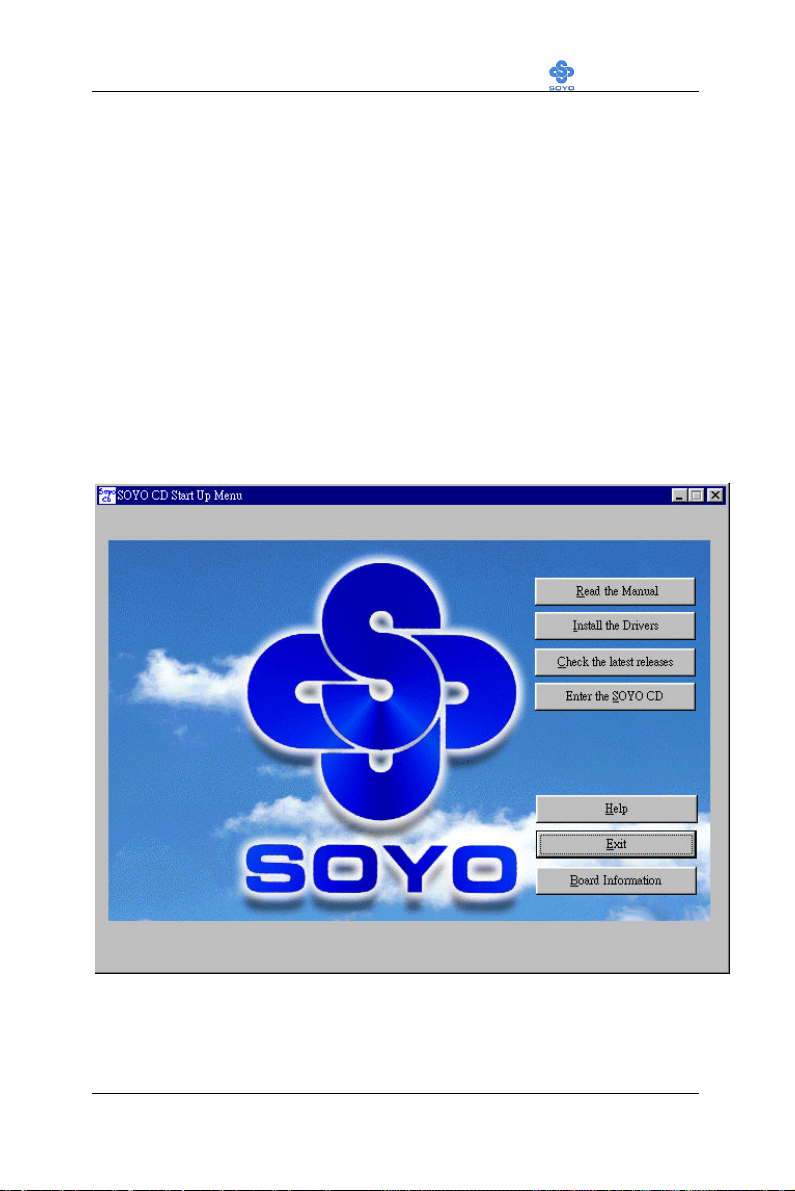
Drivers installation LI-7000
Chapter 5
THE SOYO CD
Your SY-7IWL-T Motherboard comes with a CD-ROM labeled "SOYO
CD." The SOYO CD contains (1) the user's manual file for your new
Motherboard, (2) the drivers software available for installation, and (3) a
database in HTML format with information on SOYO Motherboards and
other products.
Step 1. Insert the SOYO CD into the CD-ROM drive
The SOYO CD will auto-run, and the SOYO CD Start Up Menu will be
shown as below.
(SOYO CD Start Up Program Menu)
If you use Windows 95/98, the SOYO CD Start Up Program automatically
detects which SOYO Motherboard you own and displays the
corresponding model name.
81
Page 86
Drivers installation LI-7000
Step 2. Read SOYO [7IWL-T] Manual
Click the Read Manual button to open the user's manual file of your
Motherboard.
Please note that if the Start Up program was unable to determine which
SOYO Motherboard you own, the manual selection menu will pop up, as
shown below. Then select the user's manual file that corresponds to your
Motherboard model name and click OK.
SOYO CD Manuals
Please select your manual in the box below
and click OK.
686 boards: 586 boards:
7IWL-T
OK Back
(Manual Selection Menu)
The user's manual files included on the SOYO CD can be read in PDF
(Postscript Document) format. In order to read a PDF file, the appropriate
Acrobat Reader software must be installed in your system.
Note: The Start Up program automatically detects if the Acrobat Reader
utility is already present in your system, and otherwise prompts you on
whether or not you want to install it. You must install the Acrobat Reader
utility to be able to read the user's manual file. Follow the instructions on
your screen during installation, then once the installation is completed,
restart your system and re-run the SOYO CD.
Step 3. Install Drivers
Click the Install Drivers button to display the list of drivers software that
can be installed with your Motherboard. The Start Up program displays
the drivers available for the particular model of Motherboard you own. We
recommend that you only install those drivers.
82
Page 87
Drivers installation LI-7000
Please select the driver you want to install and click OK, You will have to
However, to display the list of all drivers software available with SOYO
Motherboards, click the Display all drivers on the SOYO CD button.
Please make sure to install only the drivers adapted to your system, or
otherwise this cause system malfunctions.
Driver Installation
restart your system after installation. Only the drivers that are relevant
to your board are displayed initially.
Intel Whitney VGA Drivers for Win 9x
Intel .inf utility for Win 9x
Intel Whitney security utility for Win 9x/NT
Whitney Winbond Hardware Doctor for Win 95/98
Cancel
Display all drivers
on the SOYO CD
OK
(Driver Installation Menu)
A short description of all available drivers follows:
Ø INTEL Whitney VGA Drivers for Win 9x
In order to be able to make use of the integrated VGA function in
your Whitney chipset, you will need to install this driver first. For
Windows 95/98 only.
Ø INTEL Whitney .inf utility for Win 9x
Windows 95 and 98 will not recognize the new INTEL Whitney
chipset properly. To update the necessary .inf files that will help
Windows recognize the Whitney chipset, please run this utility.
Ø INTEL Whitney security utility for Win 9x/NT
83
Page 88

Drivers installation LI-7000
This utility makes use of the random number generator in the FWH
of your 810/820 chipset. for Win 95/98/NT.
Ø Whitney Winbond hardware Doctor for Win 95/98
Your motherboard comes with a hardware monitoring IC. By installing
this utility Temperature, Fan speed and Voltages can be monitored. It is
also possible to set alarms when current system values exceed or fall
below pre-set values.
Select which driver you want to install and click OK, or click Cancel to
abort the driver installation and return to the main menu.
Note: Once you have selected a driver, the system will automatically exit
the SOYO CD to begin the driver installation program. When the
installation is complete, most drivers require to restart your system before
they can become active.
Step 4. Check the Latest Releases
Click the 'Check the latest Releases' button to go the SOYO Website to
automatically find the latest BIOS, manual and driver releases for your
motherboard. This button will only work if your computer is connected to
the internet through a network or modem connection. Make sure to get
your modem connection up before clicking this button.
Step 5. Enter the SOYO CD
Click the Enter SOYO CD button to enter the SOYO HTML database.
The Start Up program will activate the default HTML browser installed on
your system (for example, Internet Explorer or Netscape) to visualize the
contents of the SOYO CD.
The SOYO CD contains useful information about your Motherboard and
other SOYO products available. For your convenience, this information is
available in HTML format, similar to the format widely used on the
Internet.
84
Page 89
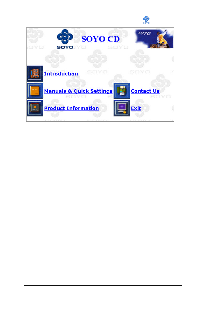
Drivers installation LI-7000
Note: If no HTML browser is installed on your system, the Start Up
program will prompt you on whether or not you would like to install the
Internet Explorer* browser. Click YES to install the HTML browser. After
the installation is complete, please restart your system. Then re-run the
SOYO CD and you will be able to browse the SOYO HTML database.
(* Internet Explorer is a Microsoft Trademark)
85
Page 90

Sigmatel Audio Drivers installation LI-7000
Chapter 6
SIGMATEL AUDIO DRIVER INSTALLATION
Installing the Sigmatel Audio Drivers under windows 9x
1. Open Device Manager.
2. PCI Multimedia Device will have a yellow marker the first time the
operating system is installed.
3. Select "Properties" on the yellow marker.
4. Select the "Driver" tab.
5. Click on "Update Driver"
6. Select the following directory:
D:\driv-all\sigmatel\win95 or D:\driv-all\sigmatel\win98se
and click OK. You will need the Windows 95 OSR 2 or windows 98
Second Edition to complete the WDM installation.
7. After informing windows of the driver directory the driver will be
installed. Restart your system after installation.
Uninstalling/Re-Installing Sigmatel Audio Drivers
1. Open Device Manager.
2. Remove the Sigmatel Audio Codec entry in the Sound, Video, and
GameControllers section. Do not change the game controller in this
audio solution.
3. Delete the sigmatel INF file in c:\windows\inf\other
4. Restart your PC for Plug and Play to reinitialize your system.
Installing the Sigmatel Audio Drivers for Windows NT
1. Double click the MULTIMEDIA icon in the control panel. The
Multimedia Properties windows will appear. Click on the Devices tab
and press the Add button.
2. Select "Unlisted or Updated Drivers" from the list of drivers in the Add
86
Page 91

Sigmatel Audio Drivers installation LI-7000
window by placing the mouse pointer over it and clicking the left
mouse button. Press the OK button.
3. The Install Driver dialog box will appear and request the path of the
location of the drivers to be installed. Enter D:\drivall\sigmatel\WinNT40 (where D: is your CDROM drive) If the
installation fails, first copy all the files in the above directory to your
harddisk and give that directory to NT.
4. Windows NT will display a dialog box asking you to restart your
system.
Press the Restart Now button to complete the installation.
Uninstalling or Updating the Sigmatel Audio Drivers
1. Double click on the MULTIMEDIA icon in the control panel. Select
the Devices tab from the Multimedia properties window.
2. Double click on the Audio Devices entry from the Multimedia devices
list. Select the driver by placing the mouse pointer over the sigmatel
driver label and clicking the left mouse button.
3. Press the REMOVE button.
4. A question box will appear to verify your decision. Press the YES
button.
5. WindowsNT will dislplay a dialog box asking you to restart your
system. Press the Restart Now button to complete the Un-installation.
SynthCore Lite Application for Windows NT 4.0
The CD also contains a SynthCore Lite application program, it can be
installed by running win-wave.exe in the D:\drive-all\sigmatel\win-wave
directory. (Were D is your CD-ROM drive letter).
Note that the NT4 installation requires a manual step at the end of the
installation. This step apllies to NT4 only. (NT4 Service Pack 4 has to be
installed, Service Pack 4 includes DirectSound 3)
87
Page 92

Sigmatel Audio Drivers installation LI-7000
1) After you run the normal installer, DO NOT reboot your system yet.
2) Go to Start > Settings > Control Panel > Multi Media
3) Select the "Devices" tab
4) Select the "Add" Button
5) Select "Unlisted or Undated Driver"
6) Browse to c:\Program Files\Staccato\SynthCore Lite\oemsetup.inf and
select this file.
7) Now look under the MIDI Devices tab, you should see the Staccato
MIDI driver.
8) Reboot your machine.
This finishes the installation process.
88
Page 93

Realtek Lan Driver Installation LI-7000
Chapter 7
REALTEK LAN DRIVER INSTALLATION
Installing the Realtek LAN Drivers under windows 9x
1. Open Device Manager.
2. Under Network Adapters there will be a yellow marker the first time
the operating system is installed.
3. Select the line with the yellow marker and press the “properties”
button.
4. Select the "Driver" tab.
5. Click on "Update Driver"
6. Select the following directory:
7. D:\driv-all\realtek\W95osr2 or D:\driv-all\realtek\win98
and click OK. You will need the Windows 95 OSR 2 or windows 98
Second Edition to
complete the installation.
8. After informing windows of the driver directory the driver will be
installed. Restart your system after installation.
Uninstalling/Re-Installing Realtek LAN Drivers
1. Open Device Manager.
2. Remove the Realtek LAN entry in the Network Adapter section.
3. Restart your PC to allow Plug and Play to reinitialize your system.
Installing the Realtek LAN Drivers for Windows NT
1. Double click the Network icon in the control panel. The Network
Properties windows will appear. Click on the Devices tab and press
the Add button.
2. Select "Unlisted or Updated Drivers" from the list of drivers in the
89
Page 94

Realtek Lan Driver Installation LI-7000
Add window by placing the mouse pointer over it and clicking the
left mouse button. Press the OK button.
3. The Install Driver dialog box will appear and request the path of the
location of the drivers to be installed. Enter D:\drivall\realtek\WinNT (where D: is your CDROM drive) If the
installation fails, first copy all the files in the above directory to your
harddisk and give that directory to NT.
4. After installation Windows NT will display a dialog box asking you
to restart your system.
5. Press the Restart Now button to complete the installation.
Uninstalling or Updating the Realtek LAN Drivers
1. Double click on the Network icon in the control panel. Select the
Devices tab from the Network properties window.
2. Double click on the Realtek Devices entry from the Network devices
list. Select the driver by placing the mouse pointer over the Realtek
LAN driver label and clicking the left mouse button.
3. Press the REMOVE button.
4. A question box will appear to verify your decision. Press the YES
button.
5. Windows NT will display a dialog box asking you to restart your
system. Press the Restart Now button to complete the Un-installation.
90
Page 95

LI-7000
91
 Loading...