

Page 1

6KM
82440 LX PCI Mainboard
User’s Guide &
Technical Reference
Page 2

®
™
About This Guide
This UserÕs Guide is for assisting system manufacturers and end users in setting
up and installing the mainboard. Information in this guide has been carefully
checked for reliability; however, no guarantee is given as to the correctness of the
contents. The information in this document is subject to change without notice.
Copyright Notice
Copyright 1997, Soyo Computer Inc. All rights reserved. This manual is
copyrighted by Soyo Computer Inc. You may not reproduce, transmit, transcribe,
store in a retrieval system, or translate into any language, in any form or by any
means, electronic, mechanical, magnetic, optical, chemical, manual, or otherwise,
any part of this publication without express written permission of Soyo Computer
Inc.
Trademarks
Soyo is a registered trademark of Soyo Computer Inc. All trademarks are the
property of their owners.
Disclaimer
Soyo Computer Inc. makes no representations or warranties regarding the
contents of this manual. We reserve the right to revise the manual or make
changes in the specifications of the product described within it at any time
without notice and without obligation to notify any person of such revision or
change. The information contained in this manual is provided for general use by
our customers. Our customers should be aware that the personal computer field is
the subject of many patents. Our customers should ensure that they take
appropriate action so that their use of our products does not infringe upon any
patents. It is the policy of Soyo Computer Inc. to respect the valid patent rights of
third parties and not to infringe upon or assist others to infringe upon such rights.
Restricted Rights Legend
Use, duplication, or disclosure by the Government is subject to restrictions set
forth in subparagraph (c)(1)(ii) of the Rights in Technical Data and Computer
Software clause at 252.277-7013.
Product Rights
Product mentioned in this manual are mentioned for identification purpose only.
Product names appearing in this manual may or may not be registered trademarks
or copyrights of their respective companies.
If you need any further information, please come to our home page on internet.
The address is Òhttp://www.soyo.com.twÓ.
Edition: May 1998
Version 1.1
Tested To Comply
C
C
F
With FCC Standards
FOR HOME OR OFFICE US
6KM SERIAL
E
Page 3

iii
Table of Contents
Chapter 1: Introduction .................................................. 1
Key Features ............................................................................... 1
Unpacking the Mainboard........................................................... 2
Electrostatic Discharge Precautions............................................ 2
Mainboard Layout w/ Default Settings ....................................... 3
Chapter 2: Hardware Setup ............................................ 5
Jumpers ....................................................................................... 5
JP5: CMOS Clear Jumper .................................................... 5
CPU Type Configuration ............................................................ 5
Memory Configuration ............................................................... 6
Multi I/O Port Addresses ............................................................ 6
Connectors .................................................................................. 7
P2 Ð ATX Power Supply Connectors.................................... 7
PS/2 Keyboard Connector ..................................................... 7
PS/2 Mouse Connector.......................................................... 7
IR Ð IR Connector ................................................................. 8
Keylock & Power LED Connector........................................ 8
SPK Ð Speaker Connector ..................................................... 8
RST Ð Hardware Reset Control ............................................. 8
IDE1/IDE2 Ð On-board Primary/Secondary IDE HDD
Connectors ............................................................................. 8
COM1/COM2 Connectors..................................................... 8
IDE LED Ð IDE HDD LED Connectors ............................... 9
FDC Connector ..................................................................... 9
PRT Ð Parallel Port Connector .............................................. 9
USB1/USB2 Ð Universal Serial Bus Connector ................... 9
PWRBT Ð ATX Power Supply On/Off Switch Connector
(Momentary Type)................................................................. 9
JP44 Ð Wake-On-LAN (WOL) Header ................................. 9
CPU, CHA: Cooling Fan Connectors ................................. 10
SB-LINK Ð PCI Audio Card Connector ............................. 10
JP10: PS/2 Keyboard WakeUp........................................... 11
Slot 1 Installation Guide ........................................................... 12
Chapter 3: BIOS Setup.................................................. 18
Standard CMOS Setup .............................................................. 19
BIOS Features Setup ................................................................. 21
Chipset Features Setup.............................................................. 24
Power Management Setup ........................................................ 28
PNP/PCI Configuration Setup .................................................. 31
Load Setup Defaults.................................................................. 33
Page 4

iv
Load BIOS Defaults.................................................................. 33
Integrated Peripherals ............................................................... 34
Supervisor Password ................................................................. 38
User Password ........................................................................... 39
IDE HDD Auto Detection ......................................................... 40
Quick Installation Guide ................................................ 41
Motherboard Layout............................................................ 41
Memory Configurations ...................................................... 41
Connectors and Jumper Settings ......................................... 42
Default I/O Settings ............................................................. 42
Page 5

1 Introduction
The 82440 LX PCI mainboard is a high-performance ATX architecture
system board that supports the Pentium II processor family. This
mainboard is fully compatible with industry standards, and adds many
technical enhancements.
Key Features
¥ Processor supports:
Ñ Intel Pentium II CPU up to 66 MHz host bus frequency (233 ~
333 MHz)
Ñ auto detection of CPU voltage
¥ DRAM controller:
Ñ supports 3 strips of 168-pin EDO /SDRAM Unbuffered
DIMM
Ñ supports auto detection of memory type
Ñ supports ECC configuration
Ñ has onboard memory configurations from 8MB to 384MB
¥ BUS controller:
Ñ complies with the PCI specifications v2.1
Ñ One 32-bit AGP slot onboard
Ñ two 32-bit PCI slots (Masters) and two ISA slots
Ñ supports Universal Serial BusÑUSB onboard
¥ Peripheral controller:
Ñ System BIOS supports ÒPlug and PlayÓ function
Ñ onboard built-in PCI Master IDE controller and floppy
controller
Ñ onboard two high speed UARTS (w/i 16550 FIFO) and
Multimode parallel port for Standard, Enhanced (EPP) and high
speed (ECP) modes, PS/2 mouse function
Ñ onboard FLASH Memory for easy BIOS upgrades
Ñ onboard support for IR function
Page 6

2 Introduction
Unpacking the Mainboard
The mainboard package contains:
¥ The 82440LX Mainboard
¥ A disc and a manual OR a CD and a Quick Installation Guide
Note: Do not unpack the mainboard until you are ready to install it.
Follow the precautions below while unpacking the mainboard.
1. Before handling the mainboard, ground yourself by grasping an
unpainted portion of the systemÕs metal chassis.
2. Remove the mainboard from its anti-static packaging and place it on
a grounded surface, component side up.
3. Check the mainboard for damage. If any chip appears loose, press
carefully to seat it firmly in its socket.
Do not apply power if the mainboard appears damaged. If there is
damage to the board contact your dealer immediately.
Electrostatic Discharge Precautions
Make sure you ground yourself before handling the mainboard or other
system components. Electrostatic discharge can easily damage the
components. Note that you must take special precaution when handling
the mainboard in dry or air-conditioned environments.
Take these precautions to protect your equipment from electrostatic
discharge:
¥ Do not remove the anti-static packaging until you are ready to install
the mainboard and other system components.
¥ Ground yourself before removing any system component from its
protective anti-static packaging. To ground yourself grasp the
expansion slot covers or other unpainted portions of the computer
chassis.
¥ Frequently ground yourself while working, or use a grounding strap.
¥ Handle the mainboard by the edges and avoid touching its
components.
Page 7
Introduction 3
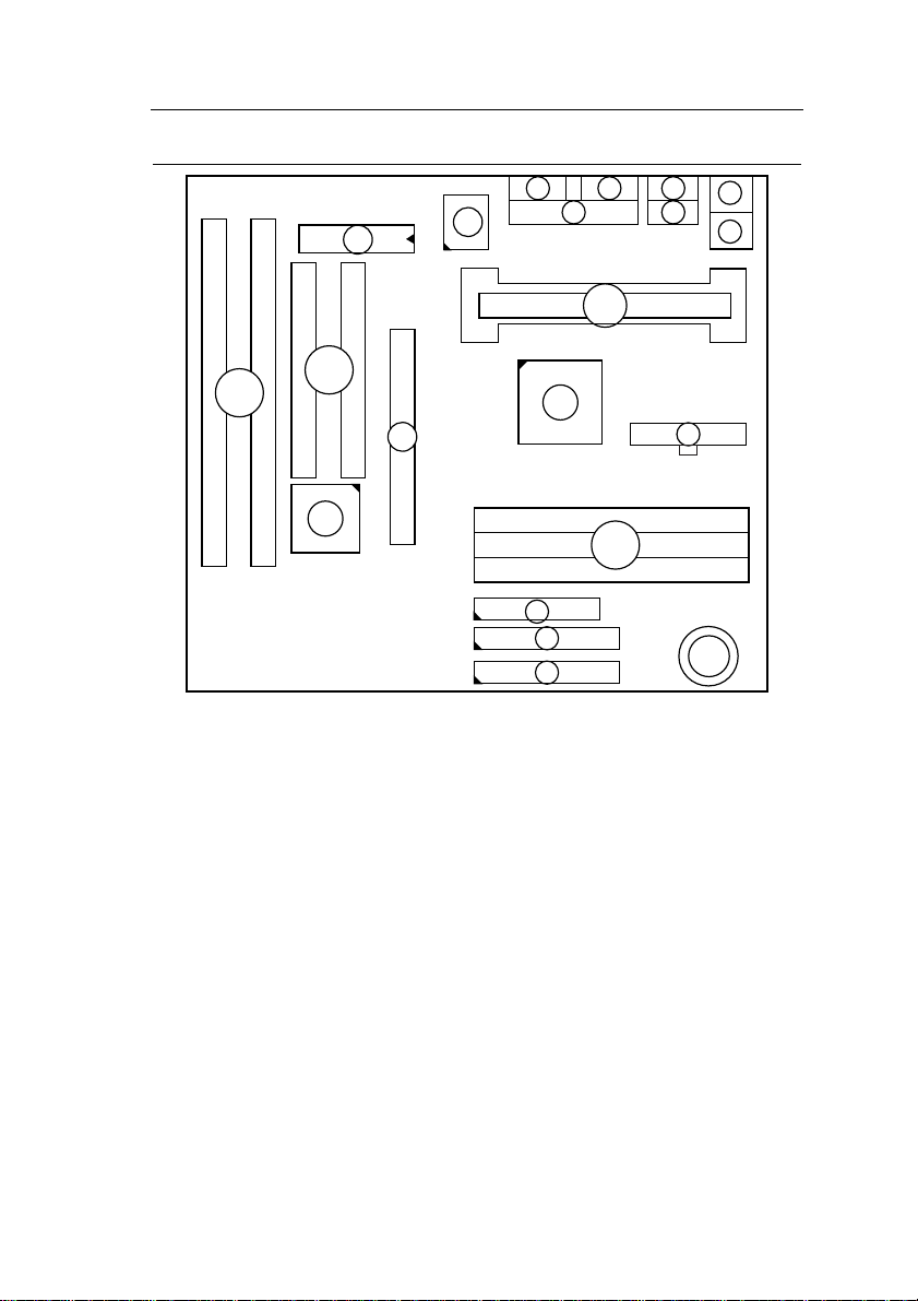
Mainboard Layout w/ Default Settings
1111
15
4
3
12
13
15
14
1
6
5
8
2
2
16
7
10
9
9
Figure 1Ð1. Mainboard Layout
1. Slot 1 for PII CPU 9. IDE1/IDE2 Connector
2. 82440LX Chipset 10. Floppy Connector
3. Ultra I/O Chip 11. COM1/COM2 Connector
4. PnP FLASH BIOS 12. Parallel Port Connector
5. ISA Slot 13. PS/2 Keyboard Connector
6. PCI Slot 14. PS/2 Mouse Connector
7. DIMM Memory Bank 15. USB 1/2 Connector
8. AGP Port 16. ATX Power Connector
17. CMOS Battery (Lithium
battery, 3V)
17
Page 8
4 Introduction
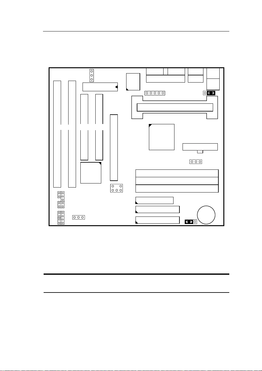
Default settings are as follows: Pentium II 233MHz* CPU, On-board
PCI Bus IDE Enabled, FDC Enabled, 2 high speed UARTS Enabled
(w/ 16550 FIFO), 1 EPP/ECP port (ECP + EPP mode), and ATX
Power Supply.
JP10
1
PS/2
KB
Conn.
PS/2
Mouse
Conn.
1
JP44
FLASH
BIOS
COM2 COM1 USB1
83977
TF-AW
PRT
IR
1
Slot 1 (for Pentium II CPU)
USB2
ISA SLOT
PCI SLOT
82443LX
ATX PW
AGP Port
SB-LINK
FDC
IDE2
IDE1
DIMM #1
DIMM #2
DIMM #3
1
CPU FAN
JP5
1
3V
Lithium
Battery
#2 #1
LED
RST PWRBT
LED
TB
+–+–
LED
IDE
PW
+– + –
Keylock
SPK
1
CHA FAN
#2
82371 AB
#1
Figure 1Ð2. Mainboard Default Setting
* The 233MHz setting is used as default and as a ÒsafeÓ frequency to
allow the board to boot-up at any time when the BIOS settings are
erased or reset. Refer to the ÒCPU Type ConfigurationÓ section of
Chapter 2.
Important: Make sure the system is well ventilated to prevent
overheating and ensure system stability.
Page 9
2 Hardware Setup
This chapter explains how to configure the mainboardÕs hardware. After
you install the mainboard, you can set jumpers, install memory on the
mainboard, and make case connections. Refer to this chapter whenever
you upgrade or reconfigure your system.
CAUTION: Turn off power to the mainboard, system chassis, and
peripheral devices before performing any work on the
mainboard or system.
Jumpers
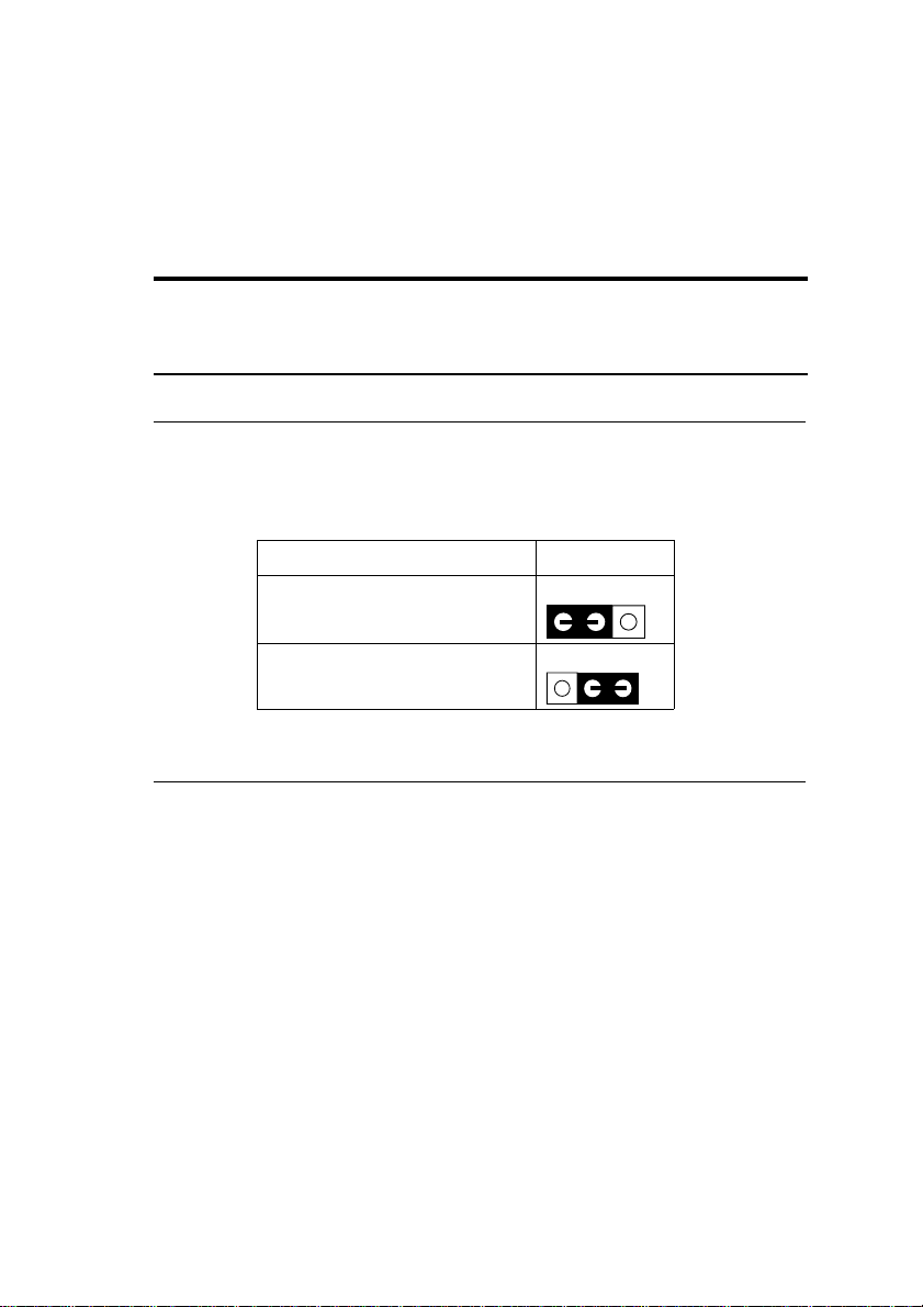
JP5: CMOS Clear Jumper
Clear the CMOS memory by setting this jumper to 2Ð3, then set the
jumper back to 1Ð2 to retain the new settings.
CMOS Setting JP5
Retain CMOS data
(default)
Clear CMOS data
CPU Type Configuration
321
321
This mainboard is designed so that it is not necessary to use any jumpers
to set the CPU frequency and multipliers onboard. Instead of using
jumpers, the settings for the CPU frequency are set through the BIOS
Setup which allows you to use any type of CPU from the Pentium II
familyÕs 233-333 range.
In order to change the CPU type, you need to enter the BIOS by pressing
the <Delete> key during boot-up and then select the ÒChipset Features
SetupÓ menu. There is an item called ÒCPU Frequency Pentium IIÓ
under this setup section and it allows you to set the frequency according
tot the speed of the Pentium II CPU that you have, which should be
clearly indicated on the case. The choices of settings are 133, 166, 200,
233, 266, 300, and 333 MHz. The 233 MHz setting is used as default
and as a ÒsafeÓ frequency which means the board can be boot-up at any
time even if the BIOS settings are erased or reset, however, there is no
Pentium II CPU of that frequency.
Page 10

6 Hardware Setup
If the frequency is set too high, the CPU will not be able to function
properly and the board will not boot up. By pressing the <Insert> key a
few times while turning on the computer, the frequency will be set back
to the default value, 233MHz, and you will be able to enter the BIOS
Setup to correct the CPU frequency value.
Memory Configuration
The mainboard supports three banks of 168-pin 3.3V EDO/SDRM
Unbuffered DIMM. The mainboard supports from 8 to 384 Mbytes
with no other restrictions on memory configurations. You can install
DRAM in any combination without having to rely on a memory
configuration table. Memory configuration is thus ÒTable-FreeÓ in any
bank.
Multi I/O Port Addresses
Default settings for multi-I/O port addresses are shown in the table
below.
Port I/O Address IRQ Status
LPT1* 378H 7 ECP + EPP
COM1 3F8H 4
COM2 2F8H 3
* If default I/O port addresses conflict with other I/O cards (e.g. sound
cards or I/O cards), you must adjust one of the I/O addresses to avoid
address conflict. (You can adjust these I/O addresses from the BIOS.
Note: Some sound cards have a default IRQ setting for IRQ7, which may
conflict with printing functions. If this occurs do not use sound
card functions at the same time you print.
Page 11
Hardware Setup 7
Connectors
Attach the mainboard to case devices, or an external battery, via
connectors on the mainboard. Refer to Figure 1-1 for connector locations
and connector pin positions.
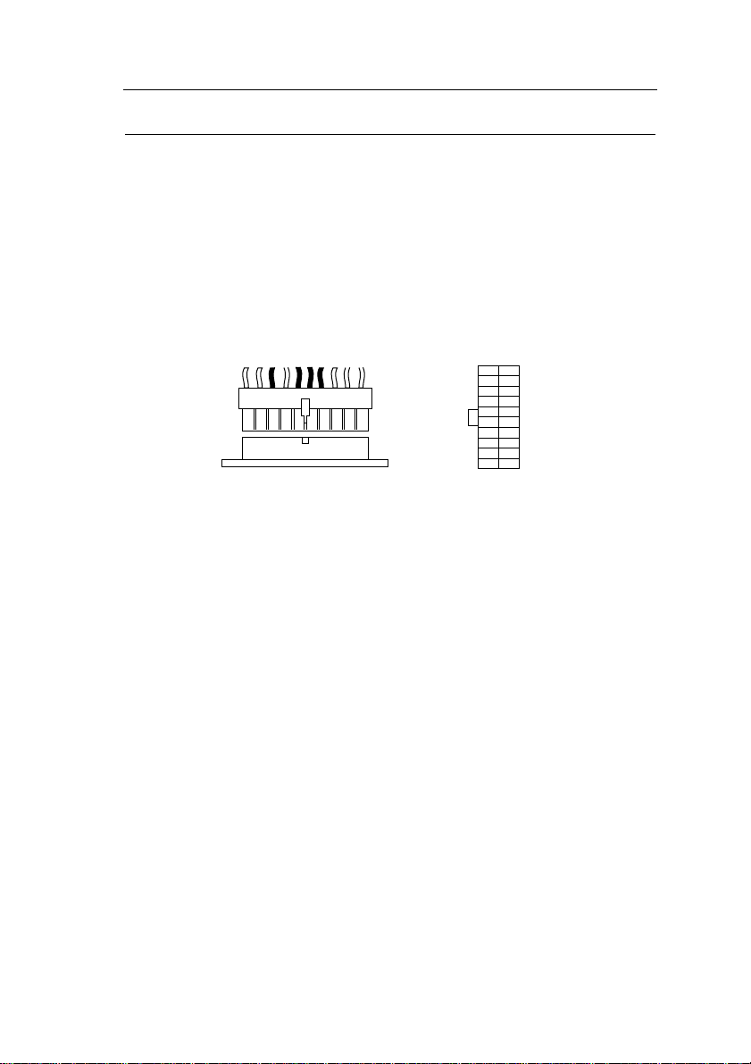
P2 – ATX Power Supply Connectors
The motherboard provides an ATX power supply connector. It is a
twenty-pin male header connector. Plug the connector from the power
directly onto the board connector while making sure the pin1 is in its
position.
3.3V
–12V
GND
PS-ON
GND
GND
GND
–5V
5V
5V
PS/2 Keyboard Connector
A six-pin female PS/2 keyboard connector is located at the rear of the
board. Plug the keyboard jack into this connector.
3.3V
3.3V
GND
5V
GND
5V
GND
PW-0K
5VSB
12V
PS/2 Mouse Connector
A six-pin female PS/2 mouse connector is located at the rear of the
board. Plug the mouse jack into this connector.
Page 12
8 Hardware Setup
IR – IR Connector
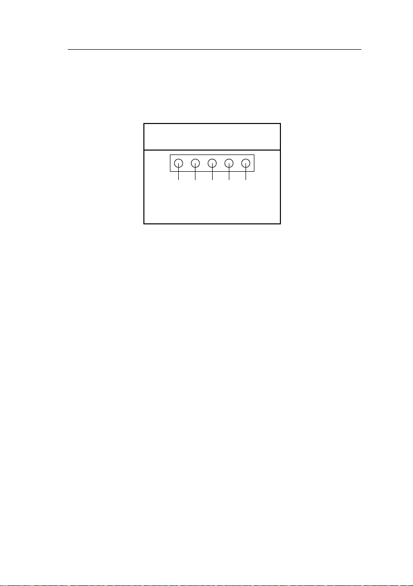
A five-pin wafer connector is for connecting to the IR device. Use the
device that has the IrDA or ASKIR specification and choose
IrDA/ASKIR from the BIOS setup.
IR Connector
Pin Assignment
VCC 1
FIRRX 2
GND 4
IRRX 3
IRTX 5
Keylock & Power LED Connector
This connector is for a lock that may be installed on the system case for
enabling or disabling the keyboard. This connector also attaches to the
caseÕs Power LED. (Pin 1, 3 for power LED, pin 4, 5 for keylock.)
SPK – Speaker Connector
Attach the system speaker to connector SPK.
RST – Hardware Reset Control
Attach the Reset switch to RST. Closing the Reset switch restarts the
system.
IDE1/IDE2 – On-board Primary/Secondary IDE HDD
Connectors
Attach on-board hard disk drives to these connectors.
COM1/COM2 Connectors
Connect COM1/COM2 devices to these connectors.
Page 13
Hardware Setup 9
IDE LED – IDE HDD LED Connectors
Attach on-board IDE device LEDs to this connector. The LED lights
when an IDE device is active.
FDC Connector
Attach floppy cable to this connector.
PRT – Parallel Port Connector
Attach parallel port cable to this connector.
USB1/USB2 – Universal Serial Bus Connector
Attach USB cable to these connectors for external USB device.
PWRBT – ATX Power Supply On/Off Switch Connector
(Momentary Type)
Attach a two-pin switch to this connector for turning the ATX power
supply on/off.
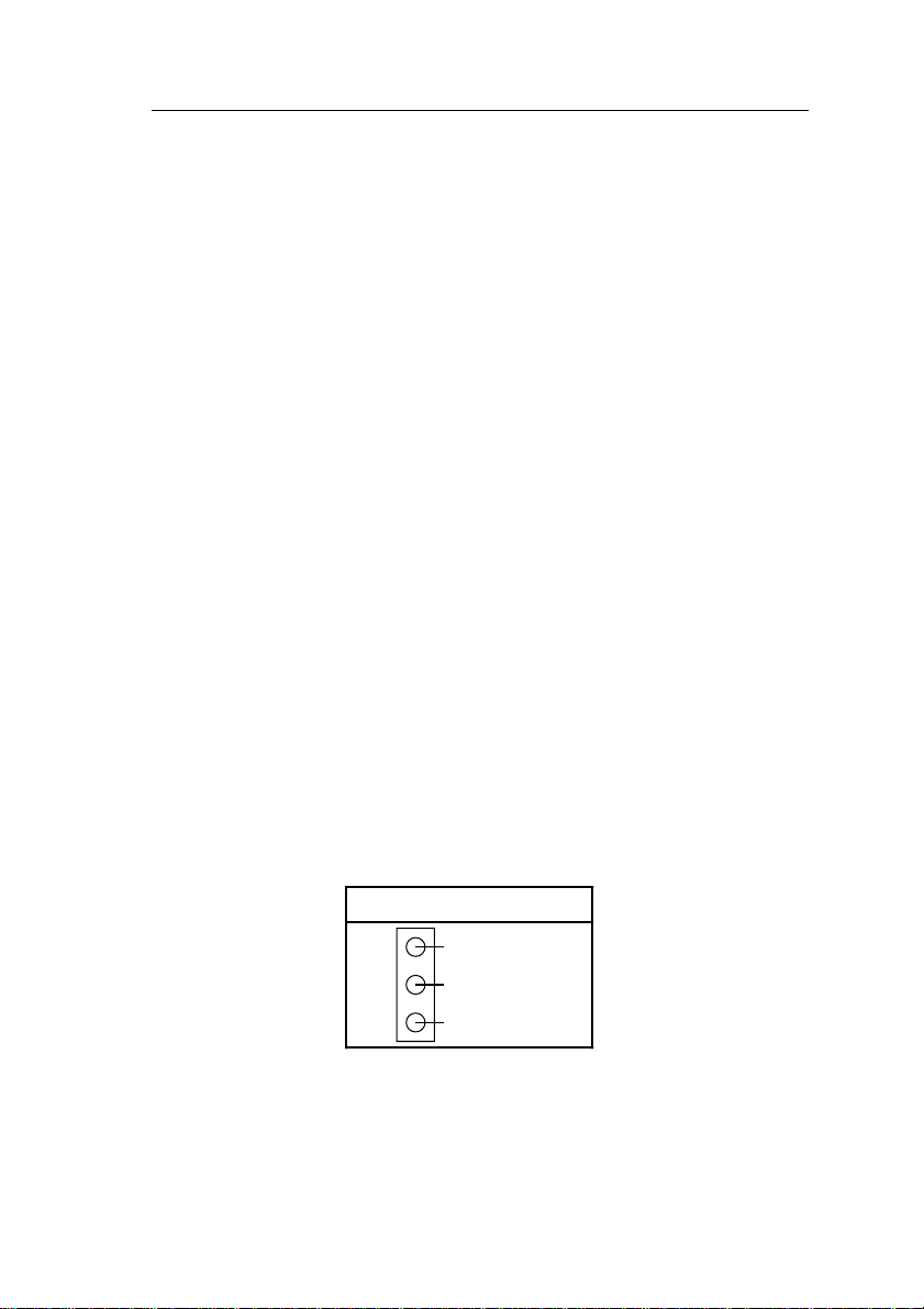
JP44 – Wake-On-LAN (WOL) Header
Attach a 3-pin connector from the LAN card which supports the WakeOn-LAN (WOL) function. This function lets users wake up the
connected computer through the LAN card. (The cable should be
included with the LAN card.)
JP44 Pin Assignment
1
2
3
5V Standby
GND
SENSOR
Page 14
10 Hardware Setup
CPU, CHA: Cooling Fan Connectors
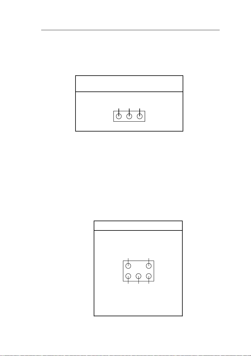
These 3-pins connectors provide 12V power for the CPU and chasis
cooling fans which matche the pin assignment of these connectors. If
you enable the Suspend Mode function in BIOS setup, these fans will
stop when the system is into the suspend mode.
CPU, CHA Cooling Fan Connectors
(Pin Assignment)
GND
12V
NC
123
Note: Make sure the pin assignment of our CPU Cooling Fan is matched
with this connector before connecting it, otherwise, you may
damage either the mainboard or the cooling fan.
SB-LINK – PCI Audio Card Connector
This 6-pin connector is used for plugging the PCI Audio cardÕs PCI
request/grant sideband signals connector into. Through this connector
requests for legacy DMA channel support as needed by some soundcards
are forwarded to the PCI Bus. Your soundcard package should include a
cable for this feature if it requires it (pin3 is left empty to make sure that
you can insert the connector only in one way.)
SB-LINK Pin Assignment
DGND
SERIRQ
GNT#
15
264
DGND
REQ#
Page 15
Hardware Setup 11
JP10: PS/2 Keyboard WakeUp
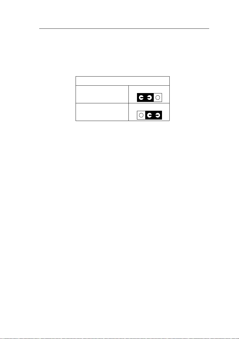
JP10 allows the user to enable the keyboard/mouse wake up function. If
JP10 is set to Enabled, the BIOS setting determines the exact response of
the mainboard to a wake up event. (See the ÒIntegrated PeripheralsÓ
section.)
JP10: PS/2 Keyboard Wake up
Wake Up Enabled
321
Wake Up Disabled
(disabled)
321
Page 16
12 Hardware Setup
Slot 1 Installation Guide
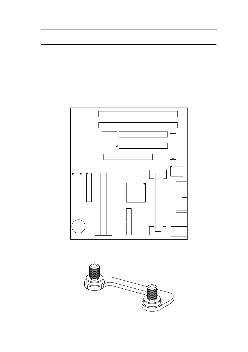
This mainboard provides a non-boxed Pentium II CPU retention set to
secure the CPU on this board. Follow the steps below to secure this type
of CPU on to your motherboard.
Step 1:
Find the ATX PW and the Slot 1 on the board and set the board in the
direction as follows before doing any installation.
Slot 1 (for Pentium II CPU)
ATX PW
Install the 2 pairs of screws, as shown in the following figure, from the
bottom of the motherboard upward onto the mainboard.
Page 17
Hardware Setup 13
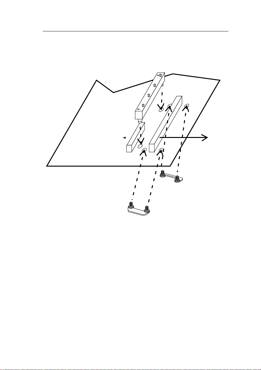
Step 2:
Insert the supporting base, which is shown below, into the two holes
directly to the left of the 2 sets of screws that have just been inserted on
to the board.
ATX PW
Slot 1
Page 18
14 Hardware Setup
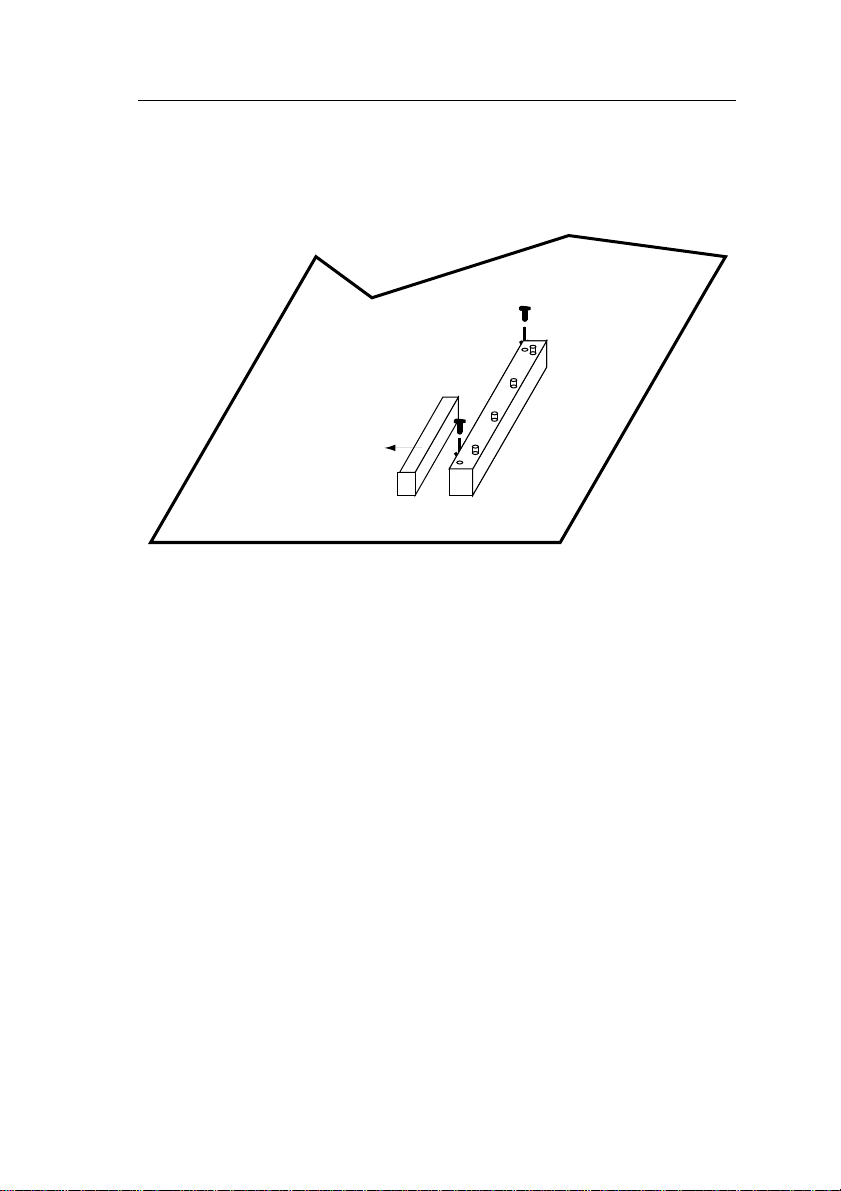
Step 3:
Insert the 2 latches into the two holes of the supporting base to secure the
CPU.
ATX PW
Page 19
Hardware Setup 15
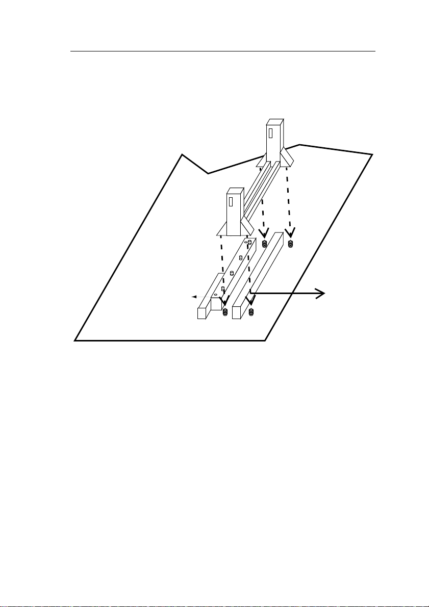
Step 4:
Set the retention clip right on the top of the 2 sets of screws which are
along the sides of Slot1 and then tighten the 4 screws on the retention
clip.
ATX PW
Slot 1
Page 20
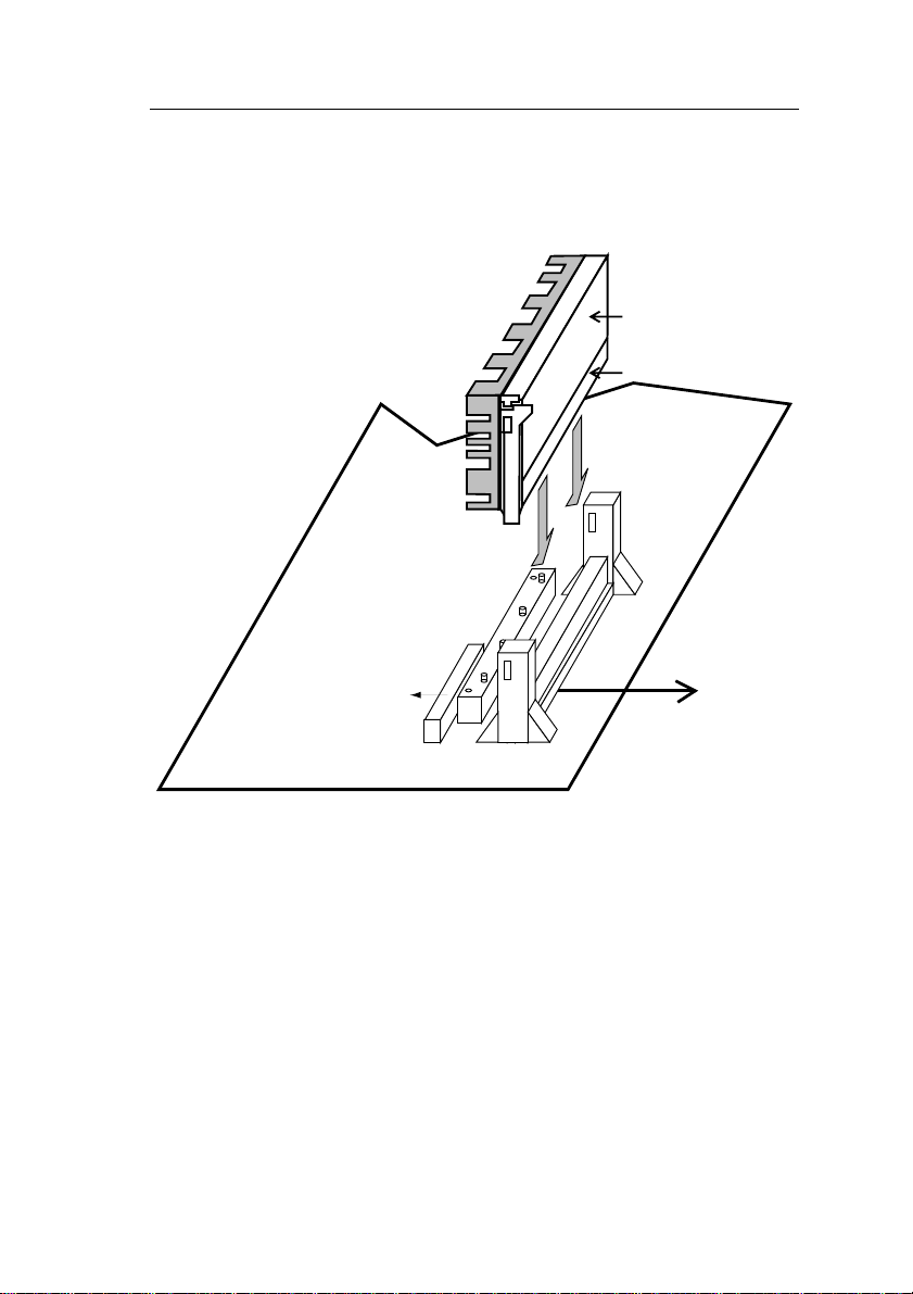
16 Hardware Setup
Step 5:
Insert the CPU into the retention clip and notice that the heat sink is on
the left hand side of the board. Lock the two latches on the sides of the
CPU to secure the CPU.
Non-boxed Pentium II
Golden Finger
ATX PW
Slot 1
Page 21
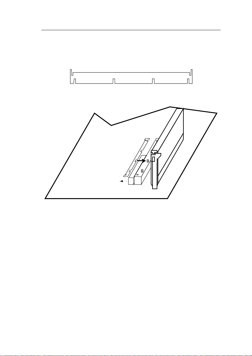
Hardware Setup 17
Step 6:
Now insert the clip portion of the CPU supporter, which is shown below,
so that the heat sink can sit on the top of the whole CPU supporter. Only
Intel specification compliant heatsinks can be fixed this way.
Top View of CPU Support Clip
ATX PW
Page 22

3 BIOS Setup
The mainboardÕs BIOS setup program is the ROM PCI/ISA BIOS from
Award Software Inc. Enter the Award BIOS programÕs Main Menu as
follows:
1. Turn on or reboot the system. After a series of diagnostic checks, you
are asked to press DEL to enter Setup.
2. Press the <DEL> key to enter the Award BIOS program and the main
screen appears:
ROM PCI/ISA BIOS
CMOS SETUP UTILITY
AWARD SOFTWARE, INC.
STANDARD CMOS SETUP
BIOS FEATURES SETUP
CHIPSET FEATURES SETUP
POWER MANAGEMENT SETUP
PNP/PCI CONFIGURATION
LOAD SETUP DEFAULTS
LOAD BIOS DEFAULTS
Esc : Quit ↑ ↓ → ← : Select Item
F10 : Save & Exit Setup (Shift) F2 : Change Color
Time, Date, Hard Disk Type...
3. Choose an option and press <Enter>. Modify the system parameters
to reflect the options installed in the system. (See the following
sections.)
4. Press <ESC> at anytime to return to the Main Menu.
5. In the Main Menu, choose ÒSAVE AND EXIT SETUPÓ to save your
changes and reboot the system. Choosing ÒEXIT WITHOUT
SAVINGÓ ignores your changes and exits the program.
The Main Menu options of the Award BIOS are described in the sections
that follow.
INTEGRATED PERIPHERALS
SUPERVISOR PASSWORD
USER PASSWORD
IDE HDD AUTO DETECTION
SAVE & EXIT SETUP
EXIT WITHOUT SAVING
Page 23

BIOS Setup 19
Standard CMOS Setup
Run the Standard CMOS Setup as follows.
1. Choose ÒSTANDARD CMOS SETUPÓ from the Main Menu. A screen
appears.
ROM PCI/ISA BIOS
STANDARD CMOS SETUP
AWARD SOFTWARE, INC.
Date (mm:dd:yy) : Fri, Dec 5 1997
Time (hh:mm:ss) : 7 : 30 : 33
HARD DISKS TYPE SIZE CYLS HEAD PRECOMP LANDZ SECTOR MODE
Primary Master : AUTO 0 0 0 0 0 0 AUTO
Primary Slave : NONE 0 0 0 0 0 0 ---Secondary Master : NONE 0 0 0 0 0 0 ---Secondary Slave : NONE 0 0 0 0 0 0 ----
Drive A : 1.44M, 3.5 in.
Drive B : None
Floppy 3 Mode Support : Disabled
Video : EGA/VGA
Halt On : All Errors
Esc : Quit ↑ ↓ → ← : Select Item PU/PD/+/– : Modify
F11 : Help (Shift) F2 : Change Color F3 : Toggle Calendar
2. Use arrow keys to move between items and select values. Modify
selected fields using PgUp/PgDn/+/Ð keys. Some fields let you enter
values directly.
Base Memory: 640K
Extended Memory: 3328K
Other Memory: 128K
Total Memory: 4096K
Date (mm/dd/yy) Type the current date.
Time (hh:mm:ss) Type the current time.
Primary
(Secondary)
Master & Slave
Choose Auto (primary master default) or from
the standard hard disk types 1 to 45 by user. If
a hard disk is not installed choose ÒNONE.Ó
Drive A & B Choose 360KB , 5 1/4 in.,
1.2MB , 5 1/4 in.,
720KB , 3 1/2 in.,
1.44M , 3 1/2 in.(default),
2.88 MB, 3 1/2 in. or
NONE
Page 24

20 BIOS Setup
Video Choose MONO,
EGA/VGA (default),
CGA40,
CGA80
Floppy 3 Mode
Support
Halt On Choose halt mode when BIOS detects system
3. When you finish, press the <ESC> key to return to the Main Menu.
Choose Disabled (default) or Enabled. When
enables this function, the system
will support
720KB/1.25MB/1.44MB 3 different
modes floppy diskette.
Note: This function is for a special disk drive
which happens to be popular in Japan.
errors:
All Errors (default) All, But Diskette
No Errors All, But Keyboard
All, But Disk/Key
Page 25

BIOS Setup 21
BIOS Features Setup
Run the BIOS Features Setup as follows.
1. Choose ÒBIOS FEATURES SETUPÓ from the Main Menu and a
screen with a list of items appears. (The screen below shows the
BIOS default settings.)
ROM PCI/ISA BIOS
BIOS FEATURES SETUP
AWARD SOFTWARE, INC.
Virus Warning : Disabled
CPU Internal Cache : Enabled
External Cache : Enabled
Quick Power on Self Test : Enabled
Boot Sequence : A,C,SCSI
Swap Floppy Drive : Disabled
Boot Up NumLock Status : On
Gate A20 Option : Fast
Typematic Rate Setting : Disabled
Typematic Rate (Chars/Sec) : 6
Typematic Delay (Msec) : 250
Security Option : Setup
PCI/VGA Palette Snoop : Disabled
Assign IRQ for VGA : Enabled
OS Select for DRAM >64MB : Non-OS2
Report no FDD for WIN95 : Yes
2. Use the arrow keys to move between items and to select values.
Modify the selected fields using the PgUp/PgDn/+/Ð keys. <F> keys
are explained below:
<F1>: ÒHelpÓ gives options available for each item.
Shift <F2>: Change color.
<F5>: Get the old values. These values are the values with
which the user started the current session.
<F6>: Load all options with the BIOS Setup default values.
<F7>: Load all options with the Power-On default values.
Video BIOS Shadow : Enabled
C8000-CBFFF Shadow : Disabled
CC000-CFFFF Shadow : Disabled
D0000-D3FFF Shadow : Disabled
D4000-D7FFF Shadow : Disabled
D8000-DBFFF Shadow : Disabled
DC000-DFFFF Shadow : Disabled
ESC : Quit ↑ ↓ → ←: Select Item
F1 : Help PU/PD/+/– : Modify
F5 : Old Values (Shift)F2 : Color
F6 : Load BIOS Defaults
F7 : Load Setup Defaults
A short description of screen items follows:
Virus Warning Enable this option will allow BIOS to protect the
boot sectors and partition tables of your hard disk.
Any attempt to write to them will cause the system to
halt and display a warning message.
CPU Internal
Cache
This option enables/disables the CPUÕs internal
cache. (The Default setting is Enabled.)
External Cache This option enables/disables the external cache
memory. (The Default setting is Enabled.)
Page 26

22 BIOS Setup
Quick Power
On Self Test
Boot Sequence Choose the boot device sequence as your need. For
Enabled provides a fast POST at boot-up .
example, ÒA, C, SCSIÓ means that BIOS will look
for an operating system first from drive A, drive C,
then SCSI device. Options of this function are:
A, C, SCSI;
C,A, SCSI;
C, CDROM, A;
CDROM, C, A;
D, A, SCSI;
E, A, SCSI;
F, A, SCSI;
SCSI, A, C;
SCSI, C, A;
C only;
LS/ZIP, C.
Swap Floppy
Drive
Boot Up Num
Lock Status
Gate A20
Option
Typematic Rate
Setting
Typematic Rate
(Chars/Sec)
Typematic
Delay (Msec)
Enabled changes the sequence of the A: and B:
drives. (The Default setting is Disabled.)
Choose On or Off. On puts numeric keypad in Num
Lock mode at boot-up. Off puts this keypad in arrow
key mode at boot-up.
Choose Fast (default) or Normal. Fast allows RAM
accesses above 1MB using the fast gate A20 line.
Enable this option to adjust the keystroke repeat rate.
Choose the rate a character keeps repeating.
Choose how long after you press a key that a
character begins repeating.
Page 27

BIOS Setup 23
Security Option Choose Setup or System. Use this feature to prevent
unauthorized system boot-up or use of BIOS Setup.
ÒSystemÓ Ð Each time the system is booted the
password prompt appears.
ÒSetupÓÐ If a password is set, the password prompt
only appears if you attempt to enter the Setup
program.
PCI/VGA
Palette Snoop
Assign IRQ For
VGA
Report no FDD
for WIN95
OS Select for
DRAM >64MB
Video or
Adapter BIOS
Shadow
3. After you have finished with the BIOS Features Setup program, press
the <ESC> key and follow the screen instructions to save or
disregard your settings.
Enabled: The color of the monitor may be incorrect
if uses with MPEG card. Enable this
option to make the monitor normal.
Disabled: Default setting.
Set this item to Enabled if your video card requires
an IRQ. Default is Disabled.
This item has the following function: Windows will
release INT line6 (normally used by the Floppy Disk
Drive) if you disable your onboard FDD and set this
item to ÔYesÕ (default). If you set it to ÔNoÕ,
windows will reserve INT 6 for your FDD, whether
it is disabled or not.
OS2: Choosing this when you are using OS/2
operation system.
Non-OS/2: Choosing this when you are using no-
OS/2 operation system.
BIOS shadow copies BIOS code from slower ROM
to faster RAM. BIOS can then execute from RAM.
These 16K segments can be shadowed from ROM to
RAM. BIOS is shadowed in a 16K segment if it is
enabled and it has BIOS present.
Page 28

24 BIOS Setup
Chipset Features Setup
The Chipset Features Setup option changes the values of the chipset
registers. These registers control system options in the computer.
Note: Change these settings only if you are familiar with the Chipset.
Run the Chipset Features Setup as follows.
1. Choose ÒCHIPSET FEATURES SETUPÓ from the Main Menu and
the following screen appears. (The screen below shows default
settings.)
ROM PCI/ISA BIOS
CHIPSET FEATURES SETUP
AWARD SOFTWARE, INC.
Auto Configuration : Enabled
DRAM Speed Selection : 60 ns
MA Wait State : Slow
EDO RAS# To CAS# Delay : 3
EDO RAS# Precharge Time : 3
EDO DRAM Read Burst : x3/3/3
EDO DRAM Write Burts : x2/2/2
DRAM Data Integrity Mode : Non-ECC
CPU-TO-PCI IDE Posting : Enabled
System BIOS Cacheable : Disabled
Video BIOS Cacheable : Disabled
Video RAM Cacheable : Disabled
8 Bit I/O Recovery Time : 1
16 Bit I/O Recovery Time : 1
Memory Hole At 15M-16M : Disabled
Delay Transaction : Disabled
AGP Aperture Size (MB) : 64
SDRAM RAS-to-CAS Delay : Fast
SDRAM RAS Precharge Time : Fast
SDRAM CAS Latency Time : 3
CPU Speed : 233MHz (66x3.5)
Spread Spectrum : Disabled
ESC : Quit ↑ ↓ → ← : Select Item
F1 : Help PU/PD/+/– : Modify
F5 : Old Values (Shift)F2 : Color
F6 : Load BIOS Defaults
F7 : Load Setup Defaults
2. Use the arrow keys to move between items and select values. Modify
selected fields using the PgUp/PgDn/+/Ð keys.
A short description of screen items follows:
Auto Configuration Enable this option (strongly
recommended) and the system
automatically sets all options on the left
side of the screen (except cache update
mode & BIOS cacheable).
If this option is Enabled you must boot
from Turbo mode.
MA Wait State Use the default setting.
EDO RAS# to CAS#
Use the default setting.
Delay
Page 29

BIOS Setup 25
EDO RAS# Precharge
Time
EDO DRAM Read Burst Use the default setting.
DRAM Write Burst Use the default setting.
Use the default setting.
DRAM Data Integrity
Mode
CPU-TO-PCI IDE
Posting
System BIOS Cacheable Disabled: The ROM area F0000H-
Video BIOS Cacheable Disabled: The video BIOS C0000H-
8Bit I/O Recovery Time Use the default setting.
16Bit I/O Recovery Time Use the default setting.
Memory Hole At 15M16M
Choose Non-ECC (default) or ECC
according to the DRAM type you have.
Use the default setting.
FFFFFH is not cached.
Enabled: The ROM area F0000H-
FFFFFH is cacheable if cache
controller is enabled.
C7FFFH is not cached.
Enabled: The video BIOS C0000H-
C7FFFH is cacheable if cache
controller is enabled.
Choose Enabled or Disabled (default).
Some interface cards will map their ROM
address to this area. If this occurs, you
should select Enabled, otherwise use
Disabled.
Delayed Transaction Use the default setting.
AGP Aperture Size AGP could use the DRAM as its video
RAM. Choose the DRAM size that you
want it to be used as video RAM. The
range is from 4MB to 256MB.
Page 30

26 BIOS Setup
SDRAM RAS-to-CAS
Delay
Use the default setting.
SDRAM RAS Precharge
Time
SDRAM CAS Latency
Time
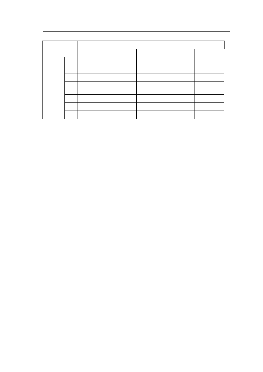
CPU Speed Select the frequency of your Pentium II
Use the default setting.
Use the default setting.
CPU from the following: 133, 233, 266,
300, 333 MHz, or Manual.
133MHz: default setting which allows the
board to boot up at any time if
a wrong CPU frequency setting
crashes the system. Press
<Insert> during boot-up to load
the BIOS default values.
Manual: User can select the frequency
and multiplier values if so
desired. SOYO does not
guarantee proper functioning of
the system if the user selects
ÒManualÓ setting, however,
since some combinations fall
outside of the INTEL
specifications. Refer to the
table on the next page for CPU
freuqency settings.
CPU Ratio If you choose ÒManualÓ in the CPU Speed
item above, then you can choose the
multiplier here. The multiplier can be
chosen from a range of 2.0 to 5.5.
CPU Host Clock Select If you choose ÒManualÓ in the CPU Speed
item above, then you can set your CPUÕs
Host Clock Frequency here. The choices
for 66MHz Host Clock CPUs are: 50, 60,
66, 68, and 75MHz.
Spread Spectrum Enabled it when you want to run the FCC
or DOC testing.
Page 31
BIOS Setup 27
CPU Frequency:
Bus Frequency
50MHz 60MHz 66MHz 68MHz 75MHz
2.0 100MHz 120MHz 133MHz 137MHz 150MHz
2.5 125MHa 150MHz 166MHz 171MHz 188MHz
CPU 3.0 150MHz 180MHz 200MHz 205MHz 225MHz
Ratio 3.5 175MHz 210MHz 233MHz
(default)
4.0 200MHz 240MHz 266MHz 274MHz 300MHz
4.5 225MHz 270MHz 300MHz 308MHz 338MHz
5.0 250MHz 300MHz 333MHz 342MHz 375MHz
Notes: If you use Bus Frequencies of 75MHz, make sure that your PCI
cards can cope with the higher PCI clock.
3. After you have finished with the Chipset Features Setup, press the
<ESC> key and follow the screen instructions to save or disregard
your settings.
239MHz 263MHz
Page 32

28 BIOS Setup
Power Management Setup
The Power Management Setup option sets the systemÕs power saving
functions.
Run the Power Management Setup as follows.
1. Choose ÒPOWER MANAGEMENT SETUPÓ from the Main Menu
and a screen with a list of items appears.
ROM PCI/ISA BIOS
CMOS SETUP UTILITY
POWER MANAGEMENT SETUP
Power Management : Disabled
PM Control by APM : Yes
Video Off Method : V/H SYNC+Blank
Video Off After : Standby
Modem Use IRQ : 3
Doze Mode : Disabled
Standby Mode : Disabled
Suspend Mode : Disabled
HDD Power Down : Disabled
VGA Active Monitor : Disabled
Soft-Off by PWR-BTN : Instant-Off
CPU Fan Off In Suspend: Enabled
Resume by Ring : Disabled
Resume by Alarm : Disabled
2. Use the arrow keys to move between items and to select values.
Modify the selected fields using the PgUp/PgDn/+/- keys.
IRQ 8 Break Suspand : Disabled
** Relead Global Timer Events **
IRQ [3-7, 9-15], NMI : Enabled
Primary IDE 0 : Disabled
Primary IDE 1 : Disabled
Secondary IDE 0 : Disabled
Secondary IDE 1 : Disabled
Floppy Disk : Disabled
Serial Port : Enabled
Parallel Port : Disabled
ESC : Quit ↑ ↓ → ←: Select Item
F1 : Help PU/PD/+/– : Modify
F5 : Old Values (Shift)F2 : Color
F6 : Load BIOS Defaults
F7 : Load Setup Defaults
A short description of selected screen items follows:
Power Management Options are as follows:
User Define Ð LetÕs you define the HDD and
system power down times
(default).
Disable Ð Disables the Green PC
Features.
Min Saving ÐDoze timer = 1 Hour
Standby timer = 1 Hour
Suspend timer = 1 Hour
HDD Power Down = 15 Min
Max Saving ÐDoze timer = 1 Min
Standby timer = 1 Min
Suspend timer = 1 Min
HDD Power Down = 1 Min
Page 33

BIOS Setup 29
PM Control by
APM
Video Off Method Choose V/H Sync+Blank (default), Blank
Video Off After Choose Standby (default), Suspend, Doze, or
Modem Use IRQ Choose Modem IRQ Setting.
Doze Mode When the set time has elapsed, the BIOS sends
Standby Mode The default is Disabled. Time is adjustable
Suspend Mode The default is Disabled. Only an SL-Enhanced
Choose Yes (default) or No. APM stands for
Advanced Power Management. To use APM,
you must run Òpower.exeÓ under DOS v6.0 or
later version.
screen, or DPMS for the selected PM mode.
N/A mode.
a command to the system to enter doze mode
(system clock drops to 33MHz). Time is
adjustable from 1 Min to 1 Hour.
from 1 Min to 1 Hour.
(or SMI) CPU can enter this mode. Time is
adjustable from 1 Min to 1 Hour. Under
Suspend mode, the CPU stops completely (no
instructions are executed.)
HDD Power Down When the set time has elapsed, the BIOS sends
a command to the HDD to power down, which
turns off the motor. Time is adjustable from 1
to 15 minutes. The default setting is Disabled.
Some older model HDDs may not support this
advanced function.
Soft-Off by PWRBTTN
VGA Active
Monitor
Choose Instant-off (default) or Delay 4 Sec.
Delay 4 Sec turns off the system power 4
seconds after pushing the power button
Choose Enabled (default) or Disabled.
Enabled Ð enables the power management
timers when a Òno activityÓ event
is detected.
Page 34

30 BIOS Setup
CPU Fan Off In
Suspend
Resume by Ring Choose Enabled or Disabled (default). This
Resume by Alarm Choose Enabled or Disabled (default).
Choose Enabled to stop the CPU fan when the
system runs into the suspend mode (refer to
Power Management Setup.)
function only works when the computer is
powered on.
Enabled Ð The system will resume active
when modem is ringing.
Disabled Ð The system will not resume when
modem is ringing.
Enabled Ð Set alarm to wake up the system
either by the date (1-31) or time
(hh:mm:ss), and if the date is set to
0, it means that the system will
wake up by the alarm everyday.
Disabled Ð The system ignores the alarm.
IRQ8 Break
Suspend
IRQ[3-7,9-15], NMI Choose Enabled (default) or Disabled. The
Primary/Secondary
IDE 0
Primary/Secondary
IDE 1
Floppy Disk/
Serial Port/
Parallel Port
3. After you have finished with the Power Management Setup, press
the <ESC> key to return to the Main Menu.
Choose Enabled or Disabled (default). Alarm
function will be activated when this function is
enabled.
BIOS monitors these items for activity. If
activity occurs from the Enabled item the
system wakes up.
Choose Enabled or Disabled (default).
Enabled Ð Enables the power management
timers when Òno activityÓ event is
detected.
Choose Enabled or Disabled.
Enabled Ð enables the power management
timers when Òno activityÓ event is
detected.
Page 35

BIOS Setup 31
PNP/PCI Configuration Setup
This option sets the mainboardÕs PCI Slots. Run this option as follows:
1. Choose ÒPNP/PCI CONFIGURATION SETUPÓ from the Main
Menu and the following screen appears. (The screen below shows
default settings.)
ROM PCI/ISA BIOS
PNP/PCI CONFIGURATION
AWARD SOFTWARE, INC.
Resources Controlled By : Manual
Reset Configuration Data : Disabled
IRQ-3 assigned to : PCI/ISA PnP*
IRQ-4 assigned to : PCI/ISA PnP*
IRQ-5 assigned to : PCI/ISA PnP*
IRQ-7 assigned to : PCI/ISA PnP*
IRQ-9 assigned to : PCI/ISA PnP*
IRQ-10 assigned to : PCI/ISA PnP*
IRQ-11 assigned to : PCI/ISA PnP*
IRQ-12 assigned to : PCI/ISA PnP*
IRQ-14 assigned to : PCI/ISA PnP*
IRQ-15 assigned to : PCI/ISA PnP*
DMA-0 assigned to : PCI/ISA PnP*
DMA-1 assigned to : PCI/ISA PnP*
DMA-3 assigned to : PCI/ISA PnP*
DMA-5 assigned to : PCI/ISA PnP*
DMA-6 assigned to : PCI/ISA PnP*
DMA-7 assigned to : PCI/ISA PnP*
*: These items will disappear when Resource Controlled. is Auto.
PCI IDE IRQ Map To : PCI-AUTO
Primary IDE INT# : A
Secondary IDE INT# : B
Used MEM Base Addr : N/A
Assign IRQ for USB : Enabled
ESC : Quit ↑ ↓ → ←: Select Item
F1 : Help PU/PD/+/– : Modify
F5 : Old Values (Shift)F2 : Color
F6 : Load BIOS Defaults
F7 : Load Setup Defaults
2. Use the arrow keys to move between items and select values.
Modify selected fields using the PgUp/PgDn/+/Ð keys.
A short description of screen items follows:
Resources
Controlled By
Manual Ð BIOS doesnÕt manage PCI/ISA PnP
card (i.e., IRQ) automatically.
Auto Ð BIOS auto manage PCI and ISA PnP
card (recommended).
Reset
Configuration
Disabled ÐRetain PnP configuration data in
BIOS.
Data
Enabled Ð Reset PnP configuration data in
BIOS.
Page 36

32 BIOS Setup
IRQX and
DMAX assigned
to
Choose PCI/ISA PnP or Legacy ISA. If the first
item is set to Manual, you could choose IRQX
and DMAX assigned to PCI/ISA PnP card or ISA
card.
PCI IDE IRQ
Map To
Primary IDE
INT#
Secondary IDE
INT#
Used MEM Base
Addr
Assign IRQ for
USB
3. After you have finished with the PCI Slot Configuration, press the
<ESC> key and follow the screen instructions to save or disregard
your settings.
Select PCI-AUTO, ISA, or assign a PCI SLOT
number (depending on which slot the PCI IDE is
inserted). The default setting is PCI-AUTO. If
PCI-AUTO does not work, then assign an
individual PCI SLOT number.
Choose INTA#, INTB#, INTC#, or INTD#. The
default setting is INTA#.
Choose INTA#, INTB#, INTC#, or INTD#. The
default setting is INTB#.
Choose C800, CC00, D000, D400, D800, or
DC00 for setting the I/O address of your add-on
card. You should ask your add-on card dealer for
the exactly I/O address. Use this function only
when problems occur while using the add-on
card.
Set this item to Enabled (default) if you use an
USB device.
Page 37

BIOS Setup 33
Load Setup Defaults
This item loads the system values you have previously saved. Choose
this item and the following message appears:
ÒLoad SETUP Defaults (Y/N)? NÓ
To use the SETUP defaults, change the prompt to ÒYÓ and press
<Enter>.
Note: The SETUP Defaults are optimized for the most stabilized
performance.
Load BIOS Defaults
Choose this item and the following message appears:
ÒLoad BIOS Defaults (Y/N)?NÓ
To use the BIOS defaults, change the prompt to ÒYÓ and press <Enter>.
Note: BIOS DEFAULTS values are adjusted for high performance. If
you run into any problems after loading BIOS DEFAULTS, please
load the SETUP DEFAULTS for the stable performance.
Page 38

34 BIOS Setup
Integrated Peripherals
The Integrated Peripherals option changes the values of the chipset
registers. These registers control system options in the computer.
Note: Change these settings only if you are familiar with the Chipset.
Run the Integrated Peripherals as follows.
1. Choose ÒIntegrated PeripheralsÓ from the Main Menu and the
following screen appears. (The screen below shows default
settings:)
IDE HDD Block Mode : Enabled
IDE Primary Master PIO : Auto
IDE Primary Slave PIO : Auto
IDE Secondary Master PIO : Auto
IDE Secondary Slave PIO : Auto
IDE Primary Master UDMA : Auto
IDE Primary Slave UDMA : Auto
IDE Secondary Master UDMA: Auto
IDE Secondary Slave UDMA : Auto
OnChip Primary PCI IDE : Enabled
OnChip Secondary PCI IDE : Enabled
USB Keyboard Support : Disabled
Power ON Function : BUTTON ONLY
Onboard FDC Controller : Enabled
ROM PCI/ISA BIOS
INTEGRATED PERIPHERALS
AWARD SOFTWARE, INC.
Onboard Serial Port 1 : 3F8/IRQ4
Onboard Serial Port 2 : 2F8/IRQ3
UART Mode Select : Normal
Onboard Parallel Port : 378/IRQ7
Parallel Port Mode : SPP
ESC : Quit ↑ ↓ → ←: Select Item
F1 : Help PU/PD/+/– : Modify
F5 : Old Values (Shift)F2 : Color
F6 : Load BIOS Defaults
F7 : Load Setup Defaults
2. Use the arrow keys to move between items and select values.
Modify selected fields using the PgUp/PgDn/+/Ð keys.
A short description of screen items follows:
IDE HDD Block Mode Choose Enabled (default) or Disabled.
Enabled invokes multi-sector transfer
instead of one sector per transfer. Not all
HDDs support this function.
IDE Primary Master PIO/
IDE Primary Slave PIO/
IDE Secondary Master
PIO/
IDE Secondary Slave PIO
Choose Auto (default) or mode 0~4.
Mode 0 is the slowest speed, and HDD
mode 4 is the fastest speed. For better
performance and stability, we suggest
you use the Auto setting to set the HDD
control timing.
Page 39

BIOS Setup 35
IDE Primary Master
UDMA/
Choose Auto (default) or Disabled.
Auto Ð Supports Ultra DMA mode.
IDE Primary Slave
UDMA/
IDE Secondary Master
UDMA/
IDE Secondary Slave
UDMA
On-chip Primary PCI
IDE/
On-chip Secondary PCI
Enabled ÐUse the on-board IDE
(default)
Disabled Ð Turn off the on-board IDE
IDE
USB Keyboard Support Choose Disabled (default) or Enabled.
You need to use the regular keyboard to
get in the BIOS Setup to enable this
function before using the USB keyboard.
POWER On Function If you enable the PS/2 keyboard wake up
function by setting JP10 to 1Ð2, you can
set the appropriate action through this
item. Refer to the table below for
details:
Setting Explanation
BUTTON ONLY
(default)
Password If you choose this option, you will
Hot Key If you choose this option, you will
Note: Please set JP10 to 2Ð3 if you choose ÒBUTTON ONLY.Ó
This setting disables the wake-up
function.
have to set your password in the ÒKB
Power On PasswordÓ item below.
You will be able to wake up the
system by entering the password or by
pressing the power button.
have to set the key combination that
will wake up the system in the ÒHot
key Power OnÓ item below.
KB POWER On Password If you selected password from the item
above, you can set your password
through this item.
Page 40

36 BIOS Setup
Hot Key Power On If you select ÒHot KeyÓ from the item
above, you will have to choose a key
combination that will wake up the
system here. Choose from Ctrl-F1 to
Ctrl-F12.
Onboard FDC Controller Enabled Ð Use the on-board floppy
controller (default).
Disabled Ð Turn off the on-board floppy
controller.
Onboard Serial Port 1/
Onboard Serial Port 2
UART Mode Select Choose Normal (default), IrDA 1.0, or
RxD, TxD Active Choose Hi, Hi; Hi, Lo (default); Lo, Hi;
IR Transmission Delay Choose Enabled or Disabled. Ask your
Onboard Parallel Port Choose the parallel port I/O address:
Parallel Port Mode Choose ECP+EPP (default), SPP, EPP,
Choose serial port 1 & 2Õs I/O address.
Do no set port 1 & 2 to the same value
except for Disabled. Choose Auto for
automatic setting for the I/O address and
IRQ.
COM1/3F8H COM3/3E8H
COM2/2F8H COM4/2E8H
(default)
ASKIR to meet the specification of your
Infra Red device.
or Lo, Lo. Ask your IR provider when
you use this function.
IR provider when you use this function.
378H/IRQ7 (default), 3BCH/IRQ7,
278H/IRQ5, or Disabled to disable this
port.
or ECP. The mode depends on your
external device that connects to this port.
Page 41

BIOS Setup 37
ECP Mode Use DMA Choose DMA3 (default) or DMA1.
This setting only works when the
Onboard Printer Mode is set at the ECP
mode.
EPP Mode Select Choose EPP1.7 or EPP1.9 (default).
3. After you have finished with the Integrated Peripherals, press the
<ESC> key and follow the screen instructions to save or disregard
your settings.
Page 42

38 BIOS Setup
Supervisor Password
Based on the setting you made in the ÒSecurity OptionÓ of the ÒBIOS
FEATURES SETUPÓ, this Main Menu item lets you configure the
system so that a password is required every time the system boots or an
attempt is made to enter the Setup program. Change the password as
follows:
1. Choose ÒSUPERVISOR PASSWORDÓ in the Main Menu and press
<Enter>. The following message appears:
ÒEnter Password:Ó
2. Enter a password and press <Enter>.
(If you do not wish to use the password function, you can just press
<Enter> and a ÒPassword disabledÓ message appears. )
3. After you enter your password, the following message appears
prompting you to confirm the new password:
ÒConfirm Password:Ó
4. Re-enter your password and then Press <ESC> to exit to the Main
Menu.
5. You have the right to change any changeable settings in the ÒCMOS
SETUP UTILITY.Ó
Important: If you forget or lose the password, the only way to access the
system is to set jumper JP5 to clear the CMOS RAM. All
setup information is lost and you must run the BIOS setup
program again.
Page 43

BIOS Setup 39
User Password
Based on the setting you made in the ÒSecurity OptionÓ of the ÒBIOS
FEATURES SETUPÓ, this Main Menu item lets you configure the
system so that a password is required every time the system boots or an
attempt is made to enter the Setup program. Change the password as
follows:
1. Choose ÒUSER PASSWORDÓ in the Main Menu and press <Enter>.
The following message appears:
ÒEnter Password:Ó
2. Enter a password and press <Enter>.
(If you do not wish to use the password function, you can just press
<Enter> and a ÒPassword disabledÓ message appears. )
3. After you enter your password, the following message appears
prompting you to confirm the new password:
ÒConfirm Password:Ó
4. Re-enter your password and then Press <ESC> to exit to the Main
Menu.
5. You are not allowed to change any setting in ÒCMOS SETUP
UTILITYÓ except change userÕs password.
Important: If you forget or lose the password, the only way to access
the system is to set jumper JP5 to clear the CMOS RAM.
All setup information is lost and you must run the BIOS
setup program again.
Page 44

40 BIOS Setup
IDE HDD Auto Detection
This Main Menu item automatically detects the hard disk type and
configures the STANDARD CMOS SETUP accordingly.
Note: This function is only valid for IDE hard disks.
HARD DISKS TYPE SIZE CYLS HEAD PRECOMP LANDZ SECTOR MODE
Primary Master : None 0 0 0 0 0 0 ----
Primary Slave : None 0 0 0 0 0 0 ---Secondary Master : None 0 0 0 0 0 0 ---Secondary Slave : None 0 0 0 0 0 0 ----
ROM PCI/ISA BIOS
CMOS SETUP UTILITY
AWARD SOFTWARE, INC.
Do you accept this drive C (Y/N)? N
ESC : Skip
Page 45
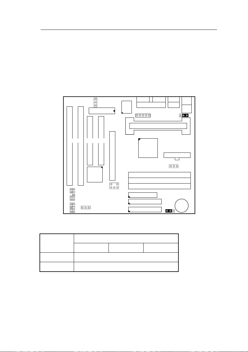
Quick Installation Guide 41
Quick Installation Guide
This Quick Installation Guide leaflet is designed for those people who
are familiar with motherboard settings to set up this new motherboard in
order to boot up the system. Refer back to the proper chapters if you
have run in to any problems.
Motherboard Layout
USB2
JP10
PS/2
KB
Conn.
PS/2
Mouse
Conn.
1
1
JP44
FLASH
BIOS
COM2 COM1 USB1
83977
TF-AW
PRT
IR
1
Slot 1 (for Pentium II CPU)
ISA SLOT
#2 #1
RST PWRBT
LED
TB
+–+–
LED
IDE
LED
PW
+– + –
SPK
Keylock
1
CHA FAN
PCI SLOT
#2
82371 AB
82443LX
AGP Port
#1
DIMM #1
DIMM #2
SB-LINK
DIMM #3
FDC
IDE2
IDE1
ATX PW
1
CPU FAN
JP5
1
3V
Lithium
Battery
Memory Configurations
DIMM BANKS
DIMM1
RAM Type FPM/EDO/SDRAM
Size 8/16/32/64/128
Note: This mainboard requires 3.3V DIMM with an access time of 70ns
or less, it supports memory size from 8 to 384MB and you may use
any combination of DIMMs in the banks.
DIMM2 DIMM3
Page 46
42 Quick Installation Guide
Connectors and Jumper Settings
CMOS clear: JP5 ATX Power Supply: P2 CPU, CHA Cooling Fan
Retain CMOS 1-2 please insert the ATX power pin 1 2 3
data (default) supply plug into this header. function GND 12V sensor
Clear CMOS data 2-3 Please connect the WOL cable
USB1 and 2 PRT SPK Keylock
Connect your USB devices to these headers printer cable header Connect the cable Connect keyboard
ATX Power Supply On/Off Switch: PWRBT of speakers to lock switch to this
Connect your power switch to this jumper (momentary switch type). this jumper jumper
IrDA (Infrared Devices Connector): IR TB Led PW Led
pin 1 2 3 4 5 Connect the
function Vcc FIRRX IRRX GND IRTX led to this jumper led to this jumper
PCI Audio Card Connector: SB-LINK .JP10: Keyboard Wake Up
1 2 3 4 5 6 Wake Up Enabled 1Ð2
GNT#1 DGND Empty REQ# DGND SERIRQ Wake Up Disabled 2Ð3
wake on LAN jumper: JP44 RST IDE Led
from your LAN card to this
jumper.
Connect the reset
button to this
jumper.
Turbo
Connect the HDD
led to this jumper.
Connect the
power
Default I/O Settings
PORT I/O Address IRQ Functionality
LPT1 378H 7 ECP + EPP
COM1 3F8H 4 Ð
COM2 2F8H 3 Ð
Note:If the default I/O settings conflict with those of other I/O cards,
such as soundcards you will have to adjust the settings of one of
them. The default settings for the onboard I/O can be changed in
the BIOS setup. Enter BIOS Setup by pressing <Delete> key
during boot-up. The I/O settings can be found under ÒIntegrated
PeripheralsÓ.
 Loading...