

Page 1

SPL 26
Petrol Leaf Vacuum
Artikel-Nr.: 3436031
Ident-Nr.: 11020
Page 2

Komponenten / Ersatzteile
Position Artikel-Nr. Beschreibung
2 343603001002 Choke Lever
3 343603001003 Primer Pump
7 343603001007 air colander cover
10 343603001010 Connector,Choke Lever
11 343603001011 Air colander Element
14 343603001014 Carburetor H619PA
23 343603001023 Lever
24 343603001024 Switch
31 343603001031 fan
35 343603001035 Fuel Filter Element
36 343603001036 Rubber stopper
37 343603001037 Inlet Pipe 220mm
38 343603001038 Pipe I 120mm
39 343603001039 Fuel Tank
40 343603001040 Chain für Benzintankdeckel
41 343603001041 sealed washer
42 343603001042 chain stpper
43 343603001043 inlet bracket
44 343603001044 air inlet
45 343603001045 Fuel Tank Cap
57 343603001057 Stop Switch Assy 6A 250V
58 343603001058 Collecting bag
59 343603001059 Choke
901 343603001901 motor 2-Takt; 25,4ccm; 0,65 kW/0,9PS
902 343603001902 Blower Pipe
903 343603001903 Pipe Connection assy.
Page 3

motor
2-Takt; 25,4ccm; 0,65 kW/0,9PS
Artikel-Nr.: 343603001901
Ident-Nr.:
Page 4

Komponenten / Ersatzteile
Position Artikel-Nr. Beschreibung
63 343603001063 Spark plug RCJ6Y
66 343603001066 Gasket
67 343603001067 Piston ring
68 343603001068 Piston
69 343603001069 Piston pin
70 343603001070 Ring
79 343603001079 Starter pulley combo
90 343603001090 Starter assy
93 343603001093 Muffler assy
100 343603001100 Ignition coil mit Zündkerzenstecker
Page 5

Page 6

1
1a
1416
15
11
8
13
7
14
9
10
16
1
17
12
2
3
4
5
6
21
14
19
20
19
18
1b
16 14
Anleitung BG_PL_26_1_SPK7:_ 09.06.2009 7:47 Uhr Seite 3
2
Helpline No. UK 0151 649 1500 / IRE 189 094 6244
Page 7
1
1a
14
16
15
11
8
13
7
14
9
10
16
1
17
12
2
3
4
5
6
21
14
19
20
19
18
1b
16 14
Anleitung BG_PL_26_1_SPK7:_ 09.06.2009 7:47 Uhr Seite 3
3
Helpline No. UK 0151 649 1500 / IRE 189 094 6244
Page 8

2 3a
3b
3c
B
11
C
A
4a 4b
2
3
4
12
13
Anleitung BG_PL_26_1_SPK7:_ 09.06.2009 7:47 Uhr Seite 4
4c
5
6
7a
7b
8a
Anleitung BG_PL_26_1_SPK7:_ 09.06.2009 7:47 Uhr Seite 5
4
Helpline No. UK 0151 649 1500 / IRE 189 094 6244
Page 9

B
11
13
4c 5
6
7a
7b 8a
Anleitung BG_PL_26_1_SPK7:_ 09.06.2009 7:47 Uhr Seite 5
5
Helpline No. UK 0151 649 1500 / IRE 189 094 6244
Page 10

9
1
2 3
4
5
6
7 8
9
10
8b
Anleitung BG_PL_26_1_SPK7:_ 09.06.2009 7:47 Uhr Seite 6
GB
Table of contents
1. Safety instructions
2. Layout
3. Intended use
4. Technical data
5. Before starting the equipment
6. Operation
7. Cleaning, maintenance, storage, transport and ordering of spare parts
8. Disposal and recycling
9. Troubleshooting
Anleitung BG_PL_26_1_SPK7:_ 09.06.2009 7:47 Uhr Seite 15
6
Helpline No. UK 0151 649 1500 / IRE 189 094 6244
Page 11

GB
Table of contents
1. Safety instructions
2. Layout
3. Intended use
4. Technical data
5. Before starting the equipment
6. Operation
7. Cleaning, maintenance, storage, transport and ordering of spare parts
8. Disposal and recycling
9. Troubleshooting
Anleitung BG_PL_26_1_SPK7:_ 09.06.2009 7:47 Uhr Seite 15
7
Helpline No. UK 0151 649 1500 / IRE 189 094 6244
Page 12

GB
10. DO NOT operate your unit near or around
flammable liquids or gases whether in or out of
doors. An explosion and/or fire may result.
11. DO NOT WEAR loose clothing, scarfs, neck
chains, unconfined long hair, and the like. Doing
so could cause injury associated with objects
being drawn into the rotating parts. Tie up long
hair and fasten it, for example with a head scarf,
cap, helmet, etc.
12. DO NOT refuel a running engine or an engine
that is hot
13. Never allow children to use the blower vac.
Explanation of the warning signs on the
equipment (see Fig. 9)
1
Read the operating instructions before you use
the blower vac.
2
Wear safety goggles to protect your eyes and
ear plugs to protect yourself from the noise.
3
Warning! Hazard!
4
Keep other people away.
5
Warning! Hot surface
6 Fuel pump
7
Never work if people – especially children - or
animals are in the danger area.
8
Never allow the blower to run without the blower
tube.
9
Sound power level with EC Directive
2000/14/EC!
10
After the unit is switched off, the motor continues
to run for a short while.
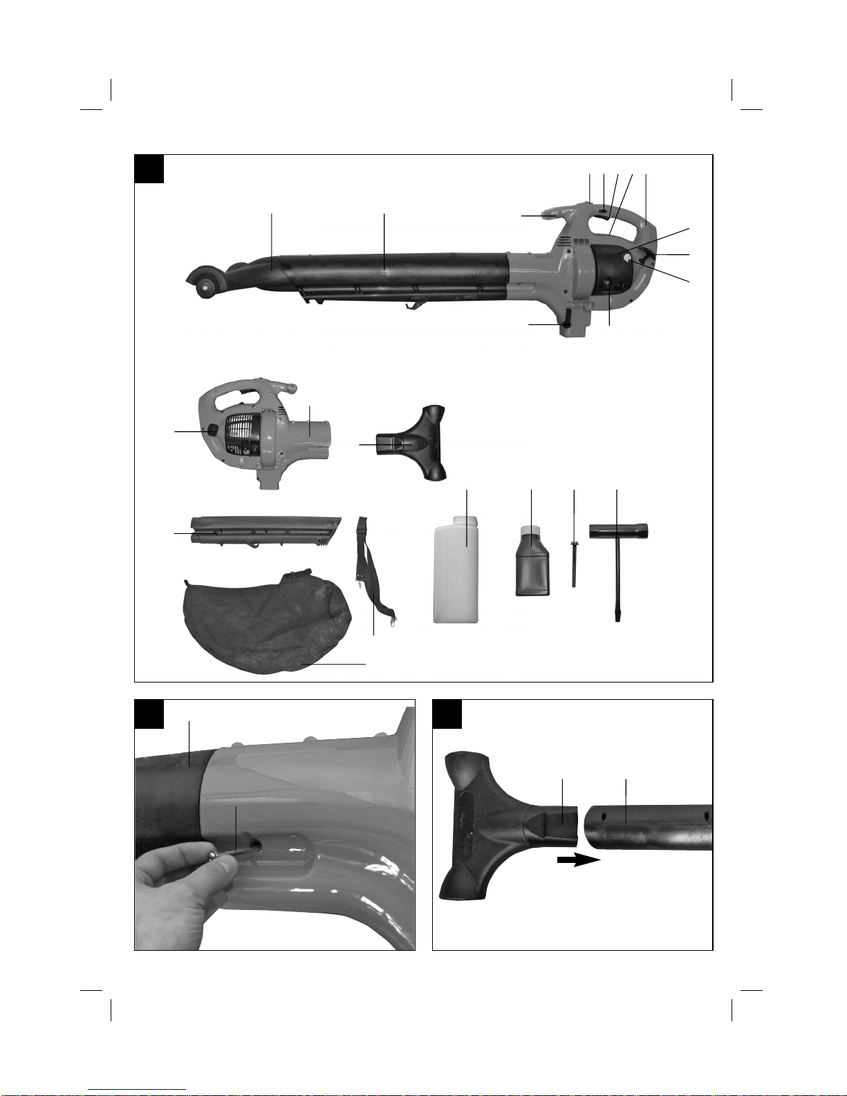
2. Layout (Fig. 1)
1. Front handle
2. Ignition switch
3. Throttle lock
4. Throttle lever
5. Spark plug boot
6. Rear handle
7. Air filter housing
8. Starter handle
9. Tank cover
10. Suction/Blower lever
11. Debris bag
12. Fuel pump (primer)
13. Start flap (choke)
14. Blower/Suction tube
15. Blower housing
16. Suction extension
17. Carrying strap
18. Spark plug wrench
19. Blower/Suction tube securing screw
20. 2-stroke oil
21. Petrol/oil mixing bottle
3. Intended use
The garden blower vac is designed to handle only
foliage and garden refuse such as grass and small
branches. Any other use is prohibited.
The machine is to be used only for its prescribed
purpose. Any other use is deemed to be a case of
misuse. The user / operator and not the
manufacturer will be liable for any damage or injuries
of any kind caused as a result of this.
Please note that our equipment has not been
designed for use in commercial, trade or industrial
applications. Our warranty will be voided if the
machine is used in commercial, trade or industrial
businesses or for equivalent purposes.
4. Technical data
Engine type 2-stroke engine; air-cooled
Engine power (max.) 0.65 kW/0.9 hp
Displacement 25,4 ccm
Max. engine speed 8000 rpm
Ignition: Electronic
Weight (with empty tank) 7,5 kg
Tank capacity 800 ml
Spark plug CMR7H
Maximum air speed 210 km/h
Maximum delivery rate 650 m3/h
Mulching ratio 10:1
Debris bag volume 55 l
Vibration a
hv
21.27 m/s
2
Sound pressure level, L
pA
97 dB(A)
Sound power level, L
WA
111 dB(A)
Anleitung BG_PL_26_1_SPK7:_ 09.06.2009 7:47 Uhr Seite 17
8
Helpline No. UK 0151 649 1500 / IRE 189 094 6244
Page 13

GB
10. DO NOT operate your unit near or around
flammable liquids or gases whether in or out of
doors. An explosion and/or fire may result.
11. DO NOT WEAR loose clothing, scarfs, neck
chains, unconfined long hair, and the like. Doing
so could cause injury associated with objects
being drawn into the rotating parts. Tie up long
hair and fasten it, for example with a head scarf,
cap, helmet, etc.
12. DO NOT refuel a running engine or an engine
that is hot
13. Never allow children to use the blower vac.
Explanation of the warning signs on the
equipment (see Fig. 9)
1 Read the operating instructions before you use
the blower vac.
2 Wear safety goggles to protect your eyes and
ear plugs to protect yourself from the noise.
3 Warning! Hazard!
4 Keep other people away.
5 Warning! Hot surface
6 Fuel pump
7 Never work if people – especially children - or
animals are in the danger area.
8 Never allow the blower to run without the blower
tube.
9 Sound power level with EC Directive
2000/14/EC!
10 After the unit is switched off, the motor continues
to run for a short while.
2. Layout (Fig. 1)
1. Front handle
2. Ignition switch
3. Throttle lock
4. Throttle lever
5. Spark plug boot
6. Rear handle
7. Air filter housing
8. Starter handle
9. Tank cover
10. Suction/Blower lever
11. Debris bag
12. Fuel pump (primer)
13. Start flap (choke)
14. Blower/Suction tube
15. Blower housing
16. Suction extension
17. Carrying strap
18. Spark plug wrench
19. Blower/Suction tube securing screw
20. 2-stroke oil
21. Petrol/oil mixing bottle
3. Intended use
The garden blower vac is designed to handle only
foliage and garden refuse such as grass and small
branches. Any other use is prohibited.
The machine is to be used only for its prescribed
purpose. Any other use is deemed to be a case of
misuse. The user / operator and not the
manufacturer will be liable for any damage or injuries
of any kind caused as a result of this.
Please note that our equipment has not been
designed for use in commercial, trade or industrial
applications. Our warranty will be voided if the
machine is used in commercial, trade or industrial
businesses or for equivalent purposes.
4. Technical data
Engine type 2-stroke engine; air-cooled
Engine power (max.) 0.65 kW/0.9 hp
Displacement 25,4 ccm
Max. engine speed 8000 rpm
Ignition: Electronic
Weight (with empty tank) 7,5 kg
Tank capacity 800 ml
Spark plug CMR7H
Maximum air speed 210 km/h
Maximum delivery rate 650 m3/h
Mulching ratio 10:1
Debris bag volume 55 l
Vibration a
hv
21.27 m/s
2
Sound pressure level, L
pA
97 dB(A)
Sound power level, L
WA
111 dB(A)
Anleitung BG_PL_26_1_SPK7:_ 09.06.2009 7:47 Uhr Seite 17
9
Helpline No. UK 0151 649 1500 / IRE 189 094 6244
Page 14

GB
5. Before starting the equipment
5.1 Assembly
Blower tube assembly (Fig. 1a)
Push the blower tube (14) into the blower housing
and secure the blower tube using the securing screw
(19). Tighten the screws (19).
Suction extension assembly (Fig. 1b)
When in suction mode, the suction extension (16)
can be assembled. For this, insert the suction
extension (16) into the blow pipe (14).
Fitting the carrying strap (Fig. 2).
Attach the carrying strap clips to the eyelets on the
handle provided for them.
Fitting the debris bag (3a – 3c)
Push the debris bag (11) over the debris bag adapter
and secure it with the Velcro fastening (A) above the
ridge (B) on the suction tube. Attach the debris bag
to the lug (C) on the blower/suction tube.
5.2 Fuel and oil
Recommended fuels
Use only a mixture of normal unleaded petrol and
special 2-stroke engine oil. Mix the fuel mixture as
indicated on the fuel mixing table.
Please note: Do not use a fuel mixture which has
been kept for longer than 90 days.
Please note: Do not use 2-stroke oil with a
recommended mixing ration of 100:1. If inadequate
lubrication causes engine damage, the
manufacturer’s engine warranty will be voided.
Please note: Only use containers designed and
approved for the purpose to transport and store fuel.
Pour the correct quantities of petrol and 2-stroke oil
into the mixing bottle (see scale printed on the bottle).
Then shake the bottle well.
5.3 Fuel mixture table
Mixing procedure: 40 parts petrol to 1 part oil
6. Operation
Please note that the statutory regulations governing
noise abatement may differ from town to town.
6.1 Cold start (4a-4c)
Fill the tank with the required amount of oil/petrol
mix. See “Fuel and oil”.
1. Place the equipment safely and securely on the
ground.
2. Set the ON/OFF switch (2) to “I” (Fig. 4a)
3. Press the throttle lever (4) until it locks (Fig. 4a)
4. Press the fuel pump (12) (Fig. 4b) 10 times.
5. Set the choke lever (13) to “ ”.
6. Hold the equipment firmly by the handle.
7. Pull the starter cable out a short way until you
feel resistance – it must be pulled evenly and
quickly to start the engine. When the engine is
running, set the choke lever to “ “.
8. Allow the engine to warm up for approx. 10
seconds.
9. Press the throttle lever lock. The throttle lever will
jump back into its idling position.
NOTE: If engine fails to start after repeated attempts,
refer to Troubleshooting section.
NOTE: Always pull starter rope straight out. Pulling
starter at an angle will cause rope to rub against the
eyelet. This friction will cause the rope to fray and
wear more quickly. Always hold starter handle when
rope retracts. Never allow rope to snap back from
extended position. This could cause rope to snag or
fray and also damage the starter assembly.
6.2 STARTING A WARM ENGINE (Engine has
been stopped for no more than 15-20
minutes)
1. Pull starter rope again. Engine should start with
ONE or TWO pulls. If engine fails to start after 6
pulls, repeat steps 2 through 6 (see Starting a
cold engine).
2. If engine does not start, or starts and then stops
after 5 rope pulls, follow procedure “STARTING
A COLD ENGINE”.
Petrol 2-stroke oil
1 liter 25 ml
5 liters 125 ml
Anleitung BG_PL_26_1_SPK7:_ 09.06.2009 7:47 Uhr Seite 18
GB
6.3 STOPPING THE ENGINE
Emergency Stopping Procedure. When it is
necessary to stop blower engine immediately,
DEPRESS the switch to stop.
Normal Stopping Method. For normal stopping,
push down the throttle lock, the throttle trigger will
back to the nomal position and allow engine to return
to idle speed. Then DEPRESS and HOLD the “0”
switch until the engine stops completely.
6.4 Switching between suction and blower mode
(Fig. 1 / Item 10)
You can either blow or suck with this equipment.
To activate blower mode slide the suction/blower
lever (10) to the right
To activate suction mode slide the suction/blower
lever (10) to the front.
6.5 BLOWER OPERATIONS (FIG. 5)
Your blower is designed to easily remove debris from
patios, walkways, lawns, bushes, etc., and many
hard to reach areas where debris may accumulate.
WARNING:
Because of flying debris, always wear
American National Standards Institute (A.N.S.I.)
approved shielded safety glasses or face shield when
operating blower.
Before using your blower, review Safety Precautions
in your User Manual, and all regulations for operation
of the unit. These precautions and regulations are for
your protection.
CAUTION:
Hold the blower so that hot exhaust does
not damage clothing and is not inhaled by operator.
DO NOT
operate the blower with other people or
animals in the immediate vicinity. Allow a minimum of
30 feet (9 meters) between operator and other
people or animals.
We recommend that a face mask be worn when
operating blower in dusty areas.
Stand away from the debris, at a distance that will
easily allow you to control the direction of blown
debris. Never blow debris in direction of bystanders.
To control velocity of airstream, blower can be
operated at any speed between idle and full throttle.
Experience with the unit will help you determine the
amount of airflow necessary for each application.
6.6 VACUUM OPERATIONS
WARNING: NEVER OPERATE VACUUM WITHOUT
VACUUM BAG PROPERLY ATTACHED, AS
FLYING DEBRIS COULD CAUSE INJURY TO
OPERATOR AND BYSTANDERS. ALWAYS MAKE
SURE VACUUM BAG ZIPPER IS CLOSED
BEFORE OPERATING UNIT.
Do not vacuum hot or burning materials (e.g. hot
ash, glowin gcigarettes) from outdoor fireplaces or
barbecue pits. always wait for these materials to be
cool enough. Do not vacuum lighted smoking
material such as discarded cigars or cigarettes. Do
not operate unit near open flame.
CAUTION: This unit is designed to vacuum up debris
such as leaves, small bits of paper, small twigs,
weeds, grass clippings, etc. Do not use this unit for
any other purpose.
Do not attempt to vacuum rocks, broken glass,
bottles, tin cans or other such objects. Damage to
impeller and unit as well as operator injury could
result.
If vacuum tube is level with power unit horizontal,
rocks or large objects may be drawn into tube,
damaging the impeller.
To Operate Vacuum:
1. Follow correct starting procedures as explained
in this manual.
2. Leave the motor running at idle speed. Attach
the shoulder strap so that it lies over the left
shoulder.
CAUTION: Do not allow shoulder harness to cover,
block, or come in contact with exhaust outlet during
operation. The muffler generates heat and could
burn, melt, or damage harness strap.
3. Hold the appliance with the right hand on the
upper handle and with the left hand on the front
handle (Fig. 6).
4. For suction, swing the appliance from side to
side.
CAUTION: To avoid clogging vacuum tube. DO NOT
FORCE OR PLACE SUCTION TUBE INTO A PILE
OF DEBRIS.
VACUUM TUBE CLOGGING
To Unclog Vacuum Tube:
Turn engine “OFF”. Promptly compress vacuum bag
while it is still inflated, expelling air out of the suction
tube. This reverse airflow is usually sufficient to
dislodge most obstructions. If the obstruction cannot
be cleared by compressing vacuum bag, follow this
procedure:
Remove and inspect vacuum tubes.
Carefully clean out nozzle.
Reinstall vacuum tubes.
Anleitung BG_PL_26_1_SPK7:_ 09.06.2009 7:47 Uhr Seite 19
10
Helpline No. UK 0151 649 1500 / IRE 189 094 6244
Page 15

GB
6.3 STOPPING THE ENGINE
Emergency Stopping Procedure. When it is
necessary to stop blower engine immediately,
DEPRESS the switch to stop.
Normal Stopping Method. For normal stopping,
push down the throttle lock, the throttle trigger will
back to the nomal position and allow engine to return
to idle speed. Then DEPRESS and HOLD the “0”
switch until the engine stops completely.
6.4 Switching between suction and blower mode
(Fig. 1 / Item 10)
You can either blow or suck with this equipment.
To activate blower mode slide the suction/blower
lever (10) to the right
To activate suction mode slide the suction/blower
lever (10) to the front.
6.5 BLOWER OPERATIONS (FIG. 5)
Your blower is designed to easily remove debris from
patios, walkways, lawns, bushes, etc., and many
hard to reach areas where debris may accumulate.
WARNING: Because of flying debris, always wear
American National Standards Institute (A.N.S.I.)
approved shielded safety glasses or face shield when
operating blower.
Before using your blower, review Safety Precautions
in your User Manual, and all regulations for operation
of the unit. These precautions and regulations are for
your protection.
CAUTION: Hold the blower so that hot exhaust does
not damage clothing and is not inhaled by operator.
DO NOT operate the blower with other people or
animals in the immediate vicinity. Allow a minimum of
30 feet (9 meters) between operator and other
people or animals.
We recommend that a face mask be worn when
operating blower in dusty areas.
Stand away from the debris, at a distance that will
easily allow you to control the direction of blown
debris. Never blow debris in direction of bystanders.
To control velocity of airstream, blower can be
operated at any speed between idle and full throttle.
Experience with the unit will help you determine the
amount of airflow necessary for each application.
6.6 VACUUM OPERATIONS
WARNING: NEVER OPERATE VACUUM WITHOUT
VACUUM BAG PROPERLY ATTACHED, AS
FLYING DEBRIS COULD CAUSE INJURY TO
OPERATOR AND BYSTANDERS. ALWAYS MAKE
SURE VACUUM BAG ZIPPER IS CLOSED
BEFORE OPERATING UNIT.
Do not vacuum hot or burning materials (e.g. hot
ash, glowin gcigarettes) from outdoor fireplaces or
barbecue pits. always wait for these materials to be
cool enough. Do not vacuum lighted smoking
material such as discarded cigars or cigarettes. Do
not operate unit near open flame.
CAUTION: This unit is designed to vacuum up debris
such as leaves, small bits of paper, small twigs,
weeds, grass clippings, etc. Do not use this unit for
any other purpose.
Do not attempt to vacuum rocks, broken glass,
bottles, tin cans or other such objects. Damage to
impeller and unit as well as operator injury could
result.
If vacuum tube is level with power unit horizontal,
rocks or large objects may be drawn into tube,
damaging the impeller.
To Operate Vacuum:
1. Follow correct starting procedures as explained
in this manual.
2. Leave the motor running at idle speed. Attach
the shoulder strap so that it lies over the left
shoulder.
CAUTION: Do not allow shoulder harness to cover,
block, or come in contact with exhaust outlet during
operation. The muffler generates heat and could
burn, melt, or damage harness strap.
3. Hold the appliance with the right hand on the
upper handle and with the left hand on the front
handle (Fig. 6).
4. For suction, swing the appliance from side to
side.
CAUTION: To avoid clogging vacuum tube. DO NOT
FORCE OR PLACE SUCTION TUBE INTO A PILE
OF DEBRIS.
VACUUM TUBE CLOGGING
To Unclog Vacuum Tube:
Turn engine “OFF”. Promptly compress vacuum bag
while it is still inflated, expelling air out of the suction
tube. This reverse airflow is usually sufficient to
dislodge most obstructions. If the obstruction cannot
be cleared by compressing vacuum bag, follow this
procedure:
Remove and inspect vacuum tubes.
Carefully clean out nozzle.
Reinstall vacuum tubes.
Anleitung BG_PL_26_1_SPK7:_ 09.06.2009 7:47 Uhr Seite 19
11
Helpline No. UK 0151 649 1500 / IRE 189 094 6244
Page 16
GB
7. Cleaning, maintenance, storage,
transport and ordering of spare
parts
Always switch off the equipment and pull out the
spark boot plug before carrying out any maintenance
work.
7.1 Cleaning
Keep all safety devices, air vents and the motor
housing free of dirt and dust as far as possible.
Wipe the equipment with a clean cloth or blow it
with compressed air at low pressure.
We recommend that you clean the device
immediately each time you have finished using it.
Clean the equipment regularly with a moist cloth
and some soft soap. Do not use cleaning agents
or solvents; these could attack the plastic parts
of the equipment. Ensure that no water can seep
into the device.
VACUUM BAG CLEANING
A dirty bag will obstruct airflow, thereby reducing
vacuum efficiency.
To Clean Bag:
1. Detach vacuum bag from unit.
2. Open zipper and remove contents.
3. Turn bag INSIDE OUT and shake vigorously.
This procedure should be performed on a regular
basis.
4. Turn bag RIGHT SIDE OUT, close zipper and
attach to unit.
NOTE: If vacuum bag is unusually dirty, it should be
washed by hand in warm water with a mild detergent.
Rinse thoroughly. Let dry before using.
7.2 Maintenance of the air filter (Fig. 7a-7b)
Soiled air filters reduce the engine output by supply
too little air to the carburetor.
Regular checks are therefore essential. The air filter
should be checked after every 25 hours of use and
cleaned if necessary. If the air contains a lot of dust,
the air filter should be checked more frequently.
1. Remove the air filter cover (Fig. 7a)
2. Remove the filter element (Fig. 7b)
3. Clean the filter element by tapping it or blowing
it.
4. Assemble in reverse order.
Please note: Never clean the air filter with petrol or
inflammable solvents.
Maintenance of the spark plug (Fig. 8a-8b)
Spark plug gap = 0.6 mm. Tighten the spark plug
with a torque of 12-15 Nm.
Check the spark plug for dirt and grime after 10
hours of operation and if necessary clean it with a
copper wire brush. Thereafter service the spark plug
after every 50 hours of operation.
1. Pull off the spark plug boot (Fig. 8a) by twisting.
2. Remove the spark plug (Fig. 8b) with the
supplied spark plug wrench.
3. Assemble in reverse order.
7.3 Storage
Please note: If you fail to follow these instructions
correctly, deposits may form on the interior of the
carburetor which may result in the engine being more
difficult to start or the machine suffering permanent
damage.
1. Carry out all the maintenance work.
2. Drain the fuel out of the tank (use a conventional
plastic petrol pump from a DIY store for this
purpose).
3. When the fuel has been drained, start the
engine.
4. Allow the engine to run at idling speed until it
stops. This will clean the remainder of the fuel
out of the carburetor.
5. Leave the machine to cool (approx. 5 minutes).
6. Remove the spark plug.
7. Place a teaspoon full of 2-stroke engine oil into
the combustion chamber. Pull the starter cable
several times carefully to wet the internal
components with the oil. Fit the spark plug again.
8. Clean the exterior housing of the machine.
9. Store the machine in a cold, dry place where it is
out of the reach of ignition sources and
inflammable substances. Fertilizers and other
chemical garden products often contain
substances that accelerate the rate of corrosion
of metals. Do not store the machine on or near
fertilizers or other chemicals.
7.4 Restarting
1. Remove the spark plug.
2. Pull the starter cable several times to clean the
oil residue out of the combustion chamber.
3. Clean the spark plug contacts or fit a new spark
plug.
4. Fill the tank. See the section entitled Fuel and oil.
5. Complete steps 1-7 described under the point
entitled “Starting the engine from cold”.
Anleitung BG_PL_26_1_SPK7:_ 09.06.2009 7:47 Uhr Seite 20
12
Helpline No. UK 0151 649 1500 / IRE 189 094 6244
Page 17

13
Helpline No. UK 0151 649 1500 / IRE 189 094 6244
Page 18

Fault Possible cause Troubleshooting
The machine does not start. Correct starting procedure not
followed.
Follow the instructions for starting.
Sooted or damp spark plug Clean the spark plug or replace it
with a new one.
Incorrect carburetor setting Contact an authorized customer
service outlet or send the machine
to ISC-GmbH.
The machine starts but does not
develop its full output.
Incorrect choke lever setting Set choke lever to “ ”
Soiled air filter Clean the air filter
Incorrect carburetor setting Contact an authorized customer
service outlet or send the machine
to ISC-GmbH.
The engine does not run smoothly Incorrect electrode gap on the
spark plug
Clean the spark plug and adjust
the electrode gap or fit a new spark
plug.
Incorrect carburetor setting Contact an authorized customer
service outlet or send the machine
to ISC-GmbH.
Engine smokes excessively Incorrect fuel mix Use the correct fuel mix (see fuel
mixing table)
Incorrect carburetor setting Contact an authorized customer
service outlet or send the machine
to ISC-GmbH.
9. Troubleshooting
GB
Anleitung BG_PL_26_1_SPK7:_ 09.06.2009 7:47 Uhr Seite 22
14
Helpline No. UK 0151 649 1500 / IRE 189 094 6244
Page 19
15
Helpline No. UK 0151 649 1500 / IRE 189 094 6244
Page 20

16
Helpline No. UK 0151 649 1500 / IRE 189 094 6244
Page 21

17
Helpline No. UK 0151 649 1500 / IRE 189 094 6244
Page 22

Anleitung SGT_26:Anleitung SGT_26 31.10.2006 13:33 Uhr Seite 21
18
Helpline No. UK 0151 649 1500 / IRE 189 094 6244
PRODUCT GUARANTEE
This product is guaranteed against manufacturing defects for a period of
Year
This product is guaranteed for twenty four months from the date of original purchase. Any
defects that arises due to faulty materials or workmanship will either be replaced, refunded
or repaired free of charge where possible during this period by the dealer from whom you
purchased the unit.
The guarantee is subject to the following provisions:
- The guarantee does not cover accidental damage, misuse, cabinet parts, knobs or
consumable items.
- The product must be correctly installed and operated in accordance with the instructions
contained in this manual.
- It must be used solely for domestic purpose.
- The guarantee will be rendered invalided if the product is re-sold or has been damaged
by inexpert repair.
- Specications are subject to change without notice.
- The manufacture disclaims any liability for the incidental or consequential damages.
- The guarantee is in addition to, and does not diminish your statutory or legal rights.
Guarantor: Homebase Ltd
AVERBURY MILTON KEYNES, MK9 2NW
TEL: 0845 0778888
www.homebase.co.uk
For technical support and assistance or requests for spare parts and accessories
please contact 0151 649 1500 between the following hours:
Mon - Thursday 8.45am - 5.00pm Friday 8.45am - 3.15pm
2
2
2
Page 23

Anleitung SGT_26:Anleitung SGT_26 31.10.2006 13:33 Uhr Seite 21
19
Helpline No. UK 0151 649 1500 / IRE 189 094 6244
Page 24

Unit 5 Morpeth Wharf
Twelve Quays
Birkenhead
Wirral
CH41 1LF
Contact Numbers:
Tel 0151 649 1500
Fax 0151 649 1501
 Loading...