


informamanual for
.
USER'S GUIDE
SERVICE
PARTS
SECTIONAL RANGE
FRONT MANIFOLD
BATTERY TYPE
(See Section 1, Page 2 for Models)
These instructions should be read thoroughly before attempting installation. Installation and Start Up should be performed by a qualified service technician. The Manufacturer, Southbend (1100 Old Honeycutt Rd., Fuquay-Varina, North Carolina 27526), informs you that unless the installation instructions for the above described Southbend product are followed and performed by a qualified service technician, (a person experienced in and knowledgeable concerning the installation of commercial gas and/or electrical cooking equipment) then the terms and conditions of the Manufacturer's Limited Warranty will be rendered void and no warranty of any kind shall apply.
If the equipment has been changed, altered, modified or repaired by other than a qualified service technician during or after the 12-month limited warranty period, then the manufacturer shall not be liable for any incidental or consequential damages to any person or to any property which may result from the use of the equipment thereafter. Some States do not allow the exclusion or limitation of incidental or consequential damages, so the above limitation or exclusion thereto may not apply to you.
In the event you have any questions concerning the installation, use. care, or service of the product, write Customer Service Department, Southbend, 1100 Old Honeycutt Rd., Fuquay-Varina, North Carolina 27526.
|
WARNING: Improper installation, adjustment, alteration, |
|
|
service or maintenance can cause property damage, injury or |
|
|
death. Read the installation, operating and maintenance |
|
|
instructions thoroughly before installing or servicing this |
|
|
equipment. |
|
$6.00 |
SECTIONAL RANGES |
|
(Manual Section SR) |
||

Congratulations!
today.
You will find |
toughest |
standards in the |
and |
designs have |
|
applications. |
|
Southbend |
|
TABLE OF |
|
1
3
|
1 |
|
2 |
Cooking Hints |
6 |
Maintenance |
8 |
SECTION THREE – SERVICE |
|
Adjustments |
1 |
Service |
6 |
Troubleshooting |
6 |
Schematic Drawings |
9 |
SECTION FOUR – PARTS |
|
Parts List |
1 |
CAUTION: POST IN PROMINENT LOCATION INSTRUCTIONS TO BE FOLLOWED IN THE EVENT THE SMELL OF GAS IS DETECTED. THIS INFORMATION SHALL BE OBTAINED FROM LOCAL GAS SUPPLIER.
RETAIN THIS MANUAL FOR FUTURE REFERENCE.
INTENDED FOR COMMERCIAL USE ONLY. NOT FOR HOUSEHOLD USE.
FOR YOUR SAFETY
DO NOT STORE OR USE GASOLINE OR OTHER FLAMMABLE VAPORS AND LIQUIDS IN THE VICINITY OF THIS OR ANY OTHER APPLIANCE.
KEEP AREA AROUND APPLIANCES FREE AND CLEAR FROM COMBUSTIBLES.
IN THE EVENT A GAS ODOR IS DETECTED, SHUT DOWN EQUIPMENT AT THE MAIN SHUTOFF VALVE AND CONTACT THE LOCAL GAS COMPANY OR GAS SUPPLIER FOR SERVICE.
 southbend
1100 Old Honeycutt Road A MIDDLEBY COUMHY Fuquay-Varina, NC 27526
(919)552-9161
PAX (919) 552-9798 (800)348-2558

|
|
|
|
|
|
|
EXTERIOR |
|
|
|
|
|
1/4" Main |
Electric |
||||
|
MODELS |
Width |
Depth |
Depth |
|
1 |
|
|
|
|
Total |
|
Ck. Top |
|
|
|
|
|
|
|
A |
B |
B1 |
C |
C |
D |
E |
F |
G |
H |
I |
J |
K |
L |
M |
N |
|
36" Deep |
1364 |
32" |
36- |
- |
- |
- |
3175” |
33" |
3" |
23" |
36" |
6” |
30" |
33.75” |
33.5" |
- |
- |
|
Standard Oven Unit |
||||||||||||||||||
|
|
|
|
|
|
|
|
|
|
|
|
|
|
|
|
|
||
36" Deep |
CO-1364 |
32" |
36" |
37" |
4" |
2" min |
31.75” |
33" |
3” |
23" |
36" |
6" |
30" |
33.75” |
33.5" |
2" |
21” |
|
Convention Oven Unit |
||||||||||||||||||
|
|
|
|
|
|
|
|
|
|
|
|
|
|
|
|
|
||
42" Deep |
|
|
|
|
|
|
|
|
|
|
|
|
|
|
|
|
|
|
1424 |
32" |
42” |
- |
- |
- |
3175" |
39” |
3” |
23" |
36" |
6” |
30" |
33.75" |
39.5" |
- |
- |
||
Standard Oven Unit |
||||||||||||||||||
|
|
|
|
|
|
|
|
|
|
|
|
|
|
|
|
|
||
42" Deep |
CO-1424 |
32” |
42" |
- |
4” |
- |
3175" |
39” |
3” |
23" |
36" |
6" |
30" |
33.75" |
39.5” |
2" |
21" |
|
Convention Oven Unit |
||||||||||||||||||
|
|
|
|
|
|
|
|
|
|
|
|
|
|
|
|
|
||
|
|
|
|
|
|
|
|
|
|
|
|
|
|
|
|
|
|
|
SECTIONAL RANGES
SECTION ONE — INSTALLATION
PAGE 1

Model
Number
42" UNITS
|
|
142C |
|
|
1421C |
|
|
1422C |
|
|
1423D |
|
|
1423DHT |
|
|
1424D |
|
|
1425C |
1366C |
1/2 Grate Top, 1/2 Fry Top |
1426C |
1367C |
1/2 Uniform Top, 1/2 Fry Top |
1427C |
1364DHT |
2 - 1/2 Grate Tops, 2 - 1/2 Uniform Tops |
1424DHT |
|
RANGES - WITH OPEN CABINET BASES |
|
136C-1 |
Graduated Heat Top |
142C-1 |
1361C-1 |
Fry Top |
1421C-1 |
1362C-1 |
Uniform Heat Top |
1422C-1 |
1363D-1 |
Grate Top, 6 Burners |
1423D-1 |
1363DHT-1 |
Front 3 Open Burners - Rear 1 Piece |
|
|
Solid Hot Top Plate |
1423DHT-1 |
1364D-1 |
Grate Top, 4 Burners |
1424D-1 |
161C-1 |
Fry Top - Half Section |
121C-1 |
162C-1 |
Uniform Heat Top - Half Section |
122C-1 |
164D-1 |
Grate Top, 2 Burners - Half Section |
124D-1 |
1366C-1 |
1/2 Grate Top, 1/2 Fry Top |
1426C-1 |
1367C-1 |
1/2 Uniform Top, 1/2 Fry Top |
1427C-1 |
1364DHT-1 |
2 - 1/2 Grate Tops, 2-1/2 Uniform Tops |
1424DHT-1 |
164DHT-1 |
1-1/2 Grate Top, 1-1/2 Uniform Top |
124DHT-1 |
163D-1 |
2 Burner 12" wide Module, 1363 Match |
|
|
RANGES - WITHOUT OVEN OR CABINET BASE |
|
136C-0 |
Graduated Heat Top |
142C-0 |
1361C-0 |
Fry Top |
1421C-0 |
1362C-0 |
Uniform Heat Top |
1422C-0 |
1363D-0 |
Grate Top, 6 Burners |
1423D-0 |
1363DHT-0 |
Front 3 Open Burners - Rear 1 Piece |
|
|
Solid Hot Top Plate |
1423DHT-0 |
1364C-0 |
Grate Top, 4 Burners |
1424C-0 |
161C-0 |
Fry Top - Half Section |
121C-0 |
162C-0 |
Uniform Heat Top - Half Section |
122C-0 |
164D-0 |
Grate Top, 2 Burners - Half Section |
124D-0 |
1366C-0 |
1/2 Grate Top, 1/2 Fry Top |
1426C-0 |
1367C-0 |
1/2 Uniform Top, 1/2 Fry Top |
1427C-0 |
1364DHT-0 |
2 - 1/2 Grate Tops, 2 -1/2 Uniform Tops |
1424DHT-0 |
164DHT-0 |
1-1/2 Grate Top, 1-1/2 Uniform Top |
124DHT-0 |
(Thermostatic Griddles have T-Prefix) |
(Convection-Type Ovens have "CO" Prefix) |
|
SECTIONAL RANGES |
|
SECTION ONE — INSTALLATION |
Litho in U.S.A |
PAGE 2 |
4-92 |

WARNING:
GENERAL:
The installation must Z223.1-Latest Edition codes, or in the absence comply with CAN/CGA Canadian Electrical
These models are for operation on Natural or Propane gases.
The appliance should be connected ONLY to the type of gas for which it is equipped. All Southbend equipment is adjusted at the factory. Check type of gas on serial plate in the compartment below the oven.
Each range is a complete unit with an individual 1-1/4" NPT manifold across its entire width. Units can be batteried by joining the unions at the ends of the manifolds. This manifold is not equipped directly with a pressure regulator. However, the manifold must be connected with an adequately sized gas appliance pressure regulator adjusted to supply a pressure to this manifold as marked on the serial plate; 6" W.C. for natural gas and 10" W.C. for propane gas. In addition, the pressure regulator must meet the following requirements:
1.The pressure regulator installed should be certified by a nationally recognized testing agency.
2.The regulator must have a maximum regulation capacity for the total connected load.
3.The regulator must have a pressure adjustment range to allow adjustment to the manifold pressure on the appliance rating plate.
4.Unless the manifold pressure of all connected appliances is the same, a separate regulator must be supplied for each unit(s) to indicate unit or units having differing manifold pressures.
5.If applicable, the vent line from the gas appliance pressure regulator shall be installed to the outdoors in accordance with local codes or, in the absence of local codes, with the National Fuel Gas Code, ANSI Z233.1-1988. Canadian installation must comply with CAN/CGA-B149.1 Natural Gas Installation Code, Code CAN/CGA-B149.2 Propane Installation Code.
An adequate gas supply is imperative. Undersized or low pressure lines restrict the volume of gas required for satisfactory performance. A steady supply pressure, between 7" W.C. and 8" W.C. for natural gas and 11" W.C. and 12" W.C. for propane gas is recommended. With all units operating simultaneously, the manifold pressure on all units should not show any
appreciable drop. Fluctuations of more than 25% on natural and 10% on propane gas will create pilot proble ms and affect burner operating characteristics. Contact your gas company for correct supply line sizes.
As an option, the unit may be supplied with a rear gas connection. The pipe size of this connection is one inch. Unless otherwise specified, this connection is welded to the right side of the manifold.
A 1/8" pressure tap is located on the manifold of each unit.
All pipe joints should be tested for leaks with a soap and water solution before operating the unit. The test pressure should not exceed 14" W.C.
CAUTION: THIS APPLIANCE AND ITS INDIVIDUAL SHUTOFF VALVE MUST BE
DISCONNECTED FROM THE GAS SUPPLY PIPING SYSTEM DURING ANY PRESSURE TESTING OF THAT SYSTEM AT TEST PRESSURES IN EXCESS OF 112 PSIG (3.45 KPA).
THIS APPLIANCE MUST BE ISOLATED FROM THE GAS SUPPLY PIPING SYSTEM BY
CLOSING ITS INDIVIDUAL MANUAL SHUTOFF VALVE DURING ANY PRESSURE TESTING OF THE GAS SUPPLY PIPING SYSTEM AT TEST PRESSURES EQUAL TO OR LESS THAN 112 PSIG (3.45 KPA).
EXHAUST FANS AND CANOPIES:
Be sure to inspect and clean ventilation system according to the ventilation equipment manufacturers instructions. Canopies are set over ranges, ovens, etc., for ventilation purposes. It is recommended that a canopy extend 6" past appliance and be located 6'6" from the floor. Filters should be installed at an angle of 45 degrees or more with the horizontal. This prevents dripping grease and facilities collecting the run-off grease in a drip pan, usually installed with a filter. A strong exhaust fan tends to created a vacuum in the room and may interfere with burner performance or may extinguish pilot flames. Fresh air openings approximately equal to the fan area will relieve such vacuum. In case of unsatisfactory performance on any appliance, check with the exhaust fan in the "OFF" position.
WALL EXHAUST FAN:
Should be installed at least two feet above the vent opening at the top of the shelter backsplash.
SECTIONAL RANGES
SECTION ONE — INSTALLATION
PAGE 3
INSTALLATION
INSTALLATION
OF
AN
FRONT OF THE
OVEN
MODEL TYPE |
SIDES |
|
REAR |
FRY TOP |
10 IN. |
|
6 IN. |
SPLIT TOP |
6 IN. LEFT |
|
6 IN. |
UNIFORM TOP |
8 IN. RIGHT |
|
|
|
|
|
|
6 BURNER OPEN TOP |
9 IN. |
|
6 IN. |
3 BURNER OPEN TOP |
9 IN. |
|
6 IN. |
3 BURNER HOT TOP (REAR) |
|
|
|
4 BURNER OPEN TOP |
6 IN. |
|
6 IN. |
2 BURNER OPEN TOP |
6 IN. |
|
6 IN. |
2 BURNER HOT TOP (REAR) |
|
|
|
GRADUATED HEAT TOP |
6 IN. |
|
6 IN. |
|
|
|
|
WARNING: ON UNITS WITH THE CONVECTION-TYPE OVEN, A MINIMUM CLEARANCE OF TWO INCHES MUST BE ALLOWED BEHIND THE MOTOR AND ANY REAR NON-COMBUSTIBLE ENCLOSURE. CARE MUST BE TAKEN TO PROVIDE ADEQUATE AIR CIRCULATION TO PREVENT THE MOTOR FROM OVERHEATING. NO ADDITIONAL CLEARANCE FROM THE SIDES AND BACK IS REQUIRED FOR SERVICE AS THE UNITS ARE SERVICEABLE FROM THE FRONT.
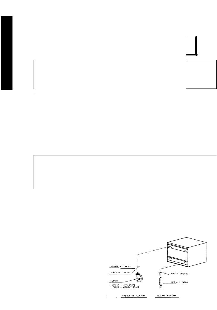
LEGS OR OPTIONAL CASTERS:
1.A set of legs or casters are packed in the unit. A threaded receptacle is fastened to the base frame at each comer. Each leg or caster has a similar mating thread.
2.Casters with locking brake are to be installed on front of unit.
3.Raise unit sufficiently to allow legs or casters to be screwed into the receptacles. For safety, "shore up" and support the unit with an adequate blocking arrangement strong enough to support the load.
4.Lower unit gently. Never drop or allow the unit to fall.
5.The legs or casters can be adjusted to overcome an uneven floor
6.After the unit has been leveled, tighten the lock nuts.
7.Casters are provided with a zerk fitting for lubrication.
SECTIONAL RANGES |
|
SECTION ONE — INSTALLATION |
Litho in U.S.A |
PAGE 4 |
4-92 |
FOR AN
WITH A
MOVABLE
DEVICE THA
USE WITH
CAN1 6.9 M79
THE APPLIANCE
DISCONNECT
MOVEMENT
WARNING:
IF DISCONNECTION OF THIS RESTRAINT IS NECESSARY TO REMOVE THE APPLIANCE FOR CLEANING, ETC., RECONNECT IT WHEN THE APPLIANCE IS MOVED TO ITS ORIGINALLY INSTALLED POSITION.
GAS CONNECTION:
On all threaded connections the pipe joint compound must be approved for used with natural and LP gas.
I. INDIVIDUAL UNITS:
1.Remove valve panel.
2.Use a long spirit level four ways; across the front top rail and rear collar plate, and along each edge.
3.A. For units without a rear gas connections connect the gas supply to the right or left side of the manifold. Be sure
to cap the unused side
B.For units with a rear gas connection the gas supply to the unit will be made at the right rear. Be certain both ends of the manifold are capped.
4.Turn off all burner valves.
5.Turn on gas supply and immediately check all gas connections for leaks. Use soapy water only. Never use an open flame.
6.Put valve panel back onto the unit.
7.Proceed to "MOUNTING SHELF OR BACKSPLASH INSTALLATION INSTRUCTIONS," if applicable.
SECTIONAL RANGES
SECTION ONE — INSTALLATION
PAGE 5
which fits any
TION AGAINST
WITH
ELECTRICAL CODE. ANSI/NFPA 70-LATEST EDITION. DO NOT CUT OR REMOVE THE GROUNDING PRONG FROM THIS PLUG.
B.208/236V - 60 HZ - SINGLE OR THREE PHASE
Ovens with this electrical rating are factory equipped with a 2-pole terminal block located behind the rear access plate located at the rear of the unit (see Diagram 3). To connect the supply wires, remove the rear access plate. Route the supply wires and the grounding wire through the strain relief fitting to the terminal block. Insert the supply wires, one each, into the two poles of the terminal block and tighten the screws. Insert the ground wire into the grounding lug and tighten the screw. Re-attach the access plate.
Three phase units are wired as above, using only two supply wires. The third wire is not used and must be properly terminated.
ASSEMBLY OF BATTERY:
1.Position the center range of the battery and carefully level unit. Use a long spirit level four ways; across front top rail and the rear collar plate, and along each edge.
2.Remove all valve panels. Mark, so they will be returned to their respective unit.
3.Bring up adjacent units, level by same method and by using the center unit as reference. Match front rails and rear collar plates. When battery is set on a masonry base and legs are not used, shims may be used. Special attention should be given to Fry Top ranges to allow proper drainage on griddles.
4.Where Spreader Plates are installed, refer to Sectional Battery Component Assembly Instructions supplied with each unit.
5.Connect units together by mating the unions. Make unions just HAND TIGHT at this time.
6.Starting at the center and working toward the ends, tighten each union gradually, going from one to another, until all are finally tight. A special thin wrench, which fits the union nut, is provided with each battery, or a chain wrench can be used.
7.Connect gas supply at right, left, or both ends. When a Spreader Plate with a "Tee" connection is inserted in a battery, the gas supply may be connected at this point. Ranges with rear connections may also be used in this respect. If five or more units are batteried, more than one supply line should be used. Each supply line should have a readily accessible, approved hand shutoff valve.
8."Open" ends of the manifold must be capped.
9.Turn off all burner valves.
10.Turn on gas supply and immediately check all the unions for leaks. USE SOAPY WATER ONLY FOR TESTING ON ALL GASES. NEVER USE AN OPEN FLAME TO CHECK FOR GAS LEAKS.
11.When entire gas system has been proved, turn off gas supply during additional installation.
12.A filler to cover the "gap" between the range fronts and tops is provided. Refer to Sectional Battery Component Assembly Instructions supplied with each unit.
SECTIONAL RANGES |
|
SECTION ONE — INSTALLATION |
Litho in U.S.A. |
PAGE 6 |
4-92 |
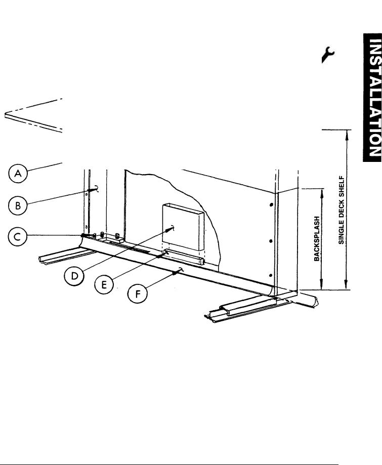
Fig. 1
1.Front panel "A" is fastened with six (6) sheet metal screws. Remove screws and panel will come loose.
2.Remove nuts and lock washers from collar plate studs "C" on unit.
3.Lower the shelf (or backsplash) on to unit allowing studs "C" to enter holes in the shelf bracket. Secure shelf bracket "B" with nuts and lock washers that were removed in instruction No. 2.
4.The flue riser extension "D" is packed with unit. Slide flue riser extension over the flue "E" protruding through the center opening of the collar plate "F". Replace panel "A". On models where flue "E" extends above collar plate approximately 4" flue extension "D" is not required.
SECTIONAL RANGES
SECTION ONE — INSTALLATION
PAGE 7
FIG. 2 - U-TYPE FRONT FILLER
APPLICATION: Standard Oven Base Unit batteried to Standard Oven Base Unit.
(#1695 Black, #1695SS Stainless Steel)
APPLICATION: Standard Oven Base Unit on the left batteried to a Convection Oven Base Unit on the right.
(#1166956 Black, #1166957 Stainless Steel) MOUNTING PROCEDURE:
If mounting holes are pre-drilled, remove screws, attach filler and secure with same screws. If mounting holes are not pre-drilled, or if pre-drilled holes do not align properly, drill holes using an 11/64" (.171 dia.) drill and secure with #10 x 1/2 slotted truss head sheet metal screws.
FIG. 3 - FLAT-TYPE FRONT FILLER
(#1692 Black, #1692SS Stainless Steel) APPLICATION: Fryer or Cabinet Base Unit battened to a Fryer or Cabinet Based Unit.
MOUNTING PROCEDURE:
Align filler equally spaced over each unit. Drill securing holes with a #38 drill, using pre-punched holes in filler as a guide and secure with #4 x % sheet metal screws.
WARNING:
TUBULAR GAS LINES ARE LOCATED ON THE LEFT SIDE OF THE STANDARD OVEN BASE UNITS BEHIND THE FILLER SECURING SCREW AREA. IF HOLES NEED TO BE DRILLED, CARE MUST BE TAKEN AND INSPECTION MADE TO INSURE GAS LINES ARE NOT PUNCTURED.
SECTIONAL RANGES |
|
SECTION ONE — INSTALLATION |
Litho in U.S.A. |
PAGE 8 |
4-92 |
FIG. 4 - L-TYPE FRONT FILLER
APPLICATION: Fryer or Cabinet Base Unit batteried with a Standard Oven Base Unit. (#1146101 Black, #1146103 Stainless Steel for Oven Base Unit on Right) (#1146100 Black, #1146102 Stainless Steel for Oven Base Unit on Left)
APPLICATION: Fryer or Cabinet Base Unit on the Left batteried with a Convection Oven Base Unit on the Right. (#1167010 Black, #1167011 Stainless Steel)
MOUNTING PROCEDURE:
If mounting holes are pre-drilled, remove screws, attach fille r and secure with same screws. If mounting holes are not predrilled, or if pre-drilled holes do not align properly, drill holes using an 11/64" (.171 dia.) drill and secure with #10 x 1/2 slotted truss head sheet metal screws.
FIG. 5 - L-TYPE FRONT FILLER
(#1166951 Black, #1166952 Stainless Steel for Convection Oven Base Unit on left)
APPLICATION: Convection Oven Base Unit on left and any Unit on right.
MOUNTING PROCEDURE:
1.RIGHT SIDE OF THE CONVECTION OVEN BASE UNIT AT CONTROL PANEL - Loosen the two screws on the right side of the front filler panel. Align the two slots in the front filler with the two screws. Push filler in until it is flush with the front of the front filler panel and retighten the two screws.
2.For Standard Oven Base Units and Convection Oven Base Units being batteried against the Convection Oven Base Unit right side, the factory will supply the single unit type left front trim. P/N 1136006 Black and 1136007 Stainless Steel for Standard Sectional Units and P/N 1166809 Black and 1166810 Stainless Steel for Convection Oven Sectional Units.
3.Slide adjacent unit up against Convection Oven Sectional and forward up against front filler.
WARNING:
TUBULAR GAS LINES ARE LOCATED ON THE LEFT SIDE OF THE STANDARD OVEN BASE UNITS BEHIND THE FILLER SECURING SCREW AREA. IF HOLES NEED TO BE DRILLED, CARE MUST BE TAKEN AND INSPECTION MADE TO INSURE GAS LINES ARE NOT PUNCTURED.
SECTIONAL RANGES
SECTION ONE — INSTALLATION
PAGE 9
APPLICATION: Sectional Battery Units with Capped Manifold.
(#1072501 Black, #1072503 Stainless Steel Left End Trim)
(#1072500 Black, #1072502 Stainless Steel Right End Trim) (#1073399 End Pipe Cap)
NOTE: Sectional type units are normally shipped with requested optional end trim attached to body side.
1.Position end trim to the underside of the front rail, tight against front and top.
2.Using the pre-punched holes in the end trim as a guide, drill (3) 1/8" (.125 dia.) holes and secure with (3) #8 x 1/2 sheet metal screws.
WARNING:
TUBULAR GAS LINES ARE LOCATED ON THE SIDES OF THE OVEN BASE UNITS BEHIND THE END TRIM SECURING SCREW AREA. IF HOLES NEED TO BE DRILLED, CARE MUST BE TAKEN AND INSPECTION MADE TO INSURE THAT GAS LINES ARE NOT PUNCTURED.
NOTE: Fryers, Spreader Cabinets, Half Section Ranges and right side of Convection Oven Base Ranges are finished and do not require fillers when installed at outer ends of batteries.
SECTIONAL RANGES |
|
SECTION ONE — INSTALLATION |
Litho in U.S.A. |
PAGE 10 |
4-92 |

Slip-on
Types of
Range
Range
Fry Top |
|
Fryer to Fryer |
Drain Cabinet to Battery Type Broiler |
Fryer to Drain Cabinet |
Drain Cabinet to Drain Cabinet |
Range to Drain Cabinet |
|
Top fillers, except "U" channel range to range filler will be labeled to identify adjoining unit usage.
PART NUMBER |
UNIT ON LEFT |
UNIT ON RIGHT |
1165435 |
ANY RANGE |
ANY RANGE |
1165277 |
ANY RANGE (except Pry Top) |
14" POT FRYER |
1165278 |
14" POT FRYER |
ANY RANGE (except Fry Top) |
1165275 |
ANY RANGE (except Fry Top) |
18" POT FRYER |
1165276 |
18" POT FRYER |
ANY RANGE (except Fry Top) |
1164484 |
BROILER OR FRY TOP RANGE OR CB |
14" POT FRYER |
|
|
|
1164485 |
14" POT FRYER |
BROILER OR FRY TOP RANGE OR CB |
1164487 |
BROILER OR FRY TOP RANGE OR CB |
18" POT FRYER |
1164486 |
18" POT FRYER |
BROILER OR FRY TOP RANGE OR CB |
1165280 |
14" POT FRYER |
14" POT FRYER |
1165279 |
18" POT FRYER |
18" POT FRYER |
1165269 |
14" POT FRYER |
18" POT FRYER |
1165270 |
18" POT FRYER |
14" POT FRYER |
1165267 |
DRAIN CABINET |
14" POT FRYER |
1165268 |
14" POT FRYER |
DRAIN CABINET |
|
|
|
1165271 |
DRAIN CABINET |
18" POT FRYER |
1165272 |
18" POT FRYER |
DRAIN CABINET |
1165266 |
ANY RANGE (except Fry Top) |
DRAIN CABINET (w/14" Fryer on Right of it) |
1165265 |
DRAIN CABINET (w/14" Fryer on Left of it) |
ANY RANGE (except Fry Top) |
1165274 |
ANY RANGE (except Fry Top) |
DRAIN CABINET (w/18" Fryer on Right of it) |
1165273 |
DRAIN CABINET (w/18" Fryer on Left of it) |
ANY RANGE (except Fry Top) |
|
|
|
1164492 |
BROILER OR FRY TOP RANGE OR CB |
DRAIN CABINET |
1164491 |
DRAIN CABINET |
BROILER OR FRY TOP RANGE OR CB |
1164488 |
32B OR 32-40 BROILER |
ANY RANGE |
1164489 |
ANY RANGE |
32B OR 32-40 BROILER |
1164490 |
ANY RANGE & 171-40 BROILER OR CB |
ANY RANGE & 171-40 BROILER OR CB |
1165297 |
DRAIN CABINET |
DRAIN CABINET |
|
|
|
NOTE: Range denotes any standard top (unless otherwise stated) including Oven Bases, Cabinet Bases and Table Top. NOTE: Top Fillers are not furnished for Spreader Plates or Spreader Cabinets.
SECTIONAL RANGES
SECTION ONE — INSTALLATION
PAGE 11
INSTALLATION

Southbend warrants |
|
and workmanship. |
|
below, then at the option |
. |
This warranty is subject |
|
If upon inspection by |
in an |
appropriate manner, |
|
neglect, abuse, accident, |
|
Specifically excluded |
|
improper utilities supply |
|
controls, and adjustments to pilots and burners. |
|
Equipment failure caused by inadequate water quality is not covered under warranty. WATER QUALITY must not exceed the following limits: Total Dissolved Solids (TDS) - 60 PPM (Parts Per Million). Hardness - 2 Grains or 35 PPM, PH Factor - 7.0 to 7.5. Water pressure 30 PSI minimum, 60 PSI maximum. Boiler maintenance is the responsibility of the owner and is not covered by warranty.
This equipment is intended for commercial use only. Warranty is void if equipment is installed in other than commercial application.
Repairs under this warranty are to be performed only by a Southbend Authorized Service Agency. Southbend can not be responsible for charges incurred from other than Authorized Southbend Agencies.
THIS WARRANTY MUST BE SHOWN TO AN AUTHORIZED SERVICE AGENCY WHEN REQUESTING IN-WARRANTY SERVICE WORK. THE AUTHORIZED SERVICE AGENCY MAY AT HIS OPTION REQUIRE PROOF OF PURCHASE.
This warranty does not cover services performed at overtime or premium labor rates nor does Southbend assume any liability for extended delays in replacing or repairing any items in the equipment beyond the control of Southbend. "Southbend shall not be liable for consequential or special damages of any nature that may arise in connection with such product or part." Should service be required at times which normally involve overtime or premium labor rates, the owner shall be charged for the difference between normal service rates and such premium rates.
In all circumstances, a maximum of one hundred miles in travel and two and one half hours (2.5) travel time shall be allowable. In all cases the closest Southbend Authorized Agency must be used.
The actual warranty time periods and exceptions are as follows: -
This warranty only covers product shipped into the 48 contiguous United States and Hawaii, one year labor, one year parts effective from the date of original purchase. There will be no labor coverage for equipment located on any island not connected by roadway to the mainland.
Exceptions to standard warranty, effective within above limitations:
Glass Windows, Door Gaskets, Rubber Seals, Light Bulbs, Ceramic Bricks,
Sight Glasses, Cathodic Descalers or Anodes |
......................................................................................90 days material and labor |
Stainless Steel Fry Pot ................................................................. |
4 years extended material warranty on fry pot only — no labor |
Stainless Steel Open Top Burners .............................................. |
4 years extended material warranty on burners only — no labor |
Pressure Steam Boiler Shell ................................................ |
Prorated 4 years extended warranty on boiler shell only — no labor |
Boiler shells which have not been properly maintained will not be covered by warranty.
In all cases parts covered by a five year warranty will be shipped FOB the factory after the first year.
Our warranty on all replacement parts which are replaced in the field by our Authorized Service Agencies will be limited to three months on labor, six months on materials (parts) effective from the date of installation. See LIMITED WARRANTY -
REPLACEMENT PARTS for conditions and limitations.
If the equipment has been changed, altered, modified or repaired by other than a qualified service technician during or after the one year limited warranty period, then the manufacturer shall not be liable for any damages to any person or to any property which may result from the use of the equipment thereafter.
"THE FOREGOING WARRANTY IS IN LIEU OF ANY AND ALL OTHER WARRANTIES EXPRESSED OR IMPLIED INCLUDING ANY IMPLIED WARRANTY OF MERCHANTABILITY OR FITNESS, AND CONSTITUTES THE ENTIRE LIABILITY OF SOUTHBEND. IN NO EVENT DOES THE LIMITED WARRANTY EXTEND BEYOND THE DURATION OF ONE YEAR FROM THE EFFECTIVE DATE OF SAID WARRANTY."
SECTIONAL RANGES
SECTION TWO — USER'S GUIDE
PAGE 1
MADE WITH A MOVABLE GAS THAT
WITH GAS
.9 M79. APPLIANCE DEVICE OR ITS
FOR
NALLY
Before turning main gas supply on, make sure all control valves are in the "OFF" position.
All units are adjusted at the factory. On new installations start with the top burner of the unit(s) furthest from the gas input to the manifold. This will purge the system of air. Turn gas supply "ON."
STANDARD-TYPE OVEN:
1.Open door, raise hold-down clips and remove oven bottom so burner is visible.
2.Turn oven burner to OFF.
3.Removel panel from spring compartment below oven door.
4.Depress RED button on safety valve and light pilot. New installations may require time to bleed air from system before pilot will become steady. The pilot flame should impinge on the bulb to cause it to glow red. If flame is too long and soft, bulb may be in "hollow" part of flame and will not glow.
5.Hold red button allowing pilot to burn approximately 45 seconds, until tip of bulb glows red, and then release button.
If pilot does not remain ignited, wait 5 minutes and repeat procedure.
NOTE: The lighting procedure is also printed on a plate attached to the front of the spring compartment cover.
6.Once pilot holds when button is released, set thermostat dial to maximum and turn ON the oven valve at manifold.
7.Burner flames should be 3/4" to 1" long.
8.Reduce thermostat setting slowly until by-pass seat in thermostat just snaps OFF. Immediately reverse rotation and turn dial counterclockwise until by-pass snaps open. The by-pass flame should be 1/8" minimum and 1/4" maximum on each port.
A small fluttering by-pass flame may flash back into the burner and ignite on the orifice when the door is quickly opened and closed. This will create a carbon deposit inside the burners which impedes proper primary air injection.
9.Check entire oven gas system for leaks.
10.Replace oven bottom and be sure hold-down clips are lowered to keep bottom in place and prevent warping. Replace spring compartment panel.
For daily shutdown turn main oven valve OFF. For complete oven shutdown turn main oven valve OFF and extinguish oven pilot
SECTIONAL RANGES |
|
SECTION TWO — USER'S GUIDE |
Litho in U.S.A. |
PAGE 2 |
4-92 |
CONVECTION-
FOR AN
SHOULD BE
A.CONTROL
1.POWER the pilot
2.FAN
In the cooking. cooling
3.
controls the cooking
both the cooking light and the oven burner will shut off.
4.FUSES: The motor and control circuitry are protected with 15 AMP fuses. One fuse is required for 115V and two fuses are required for 208/236V.
5.ADDITIONAL UNIT CONTROLS: For long life of the control box controls, a cooling blower has been incorporated into the design. This cooling blower, which is located within the right body side at the rear is
activated when the temperature inside of the box housing the controls reaches 150 degrees F at its sensing point. It will run continuously until the temperature inside of the control box drops to 135 degrees F. The cooling blower operates independent of the power switch, therefore, eliminating any control damaging residual heat rise after the unit has been completely shut down. For further protection of the control box controls if the cooling blower should happen to fail, the oven burner and the oven circulating blower motor will shut down when the temperature inside the box housing the controls reaches 225 °F at its sensing point. Refer to "TROUBLESHOOTING," Section 3, Page 7.
TO LIGHT CONVECTION OVENS ON SECTIONAL FRONT MANIFOLD UNITS:
Your oven has electronic ignition. NO MATCHES required!
1.Locate OVEN knob (#1) over oven door. Turn left to "ON" position. This position may change depending on model.
2.Locate COOK TEMP thermostat dial (#2) on control panel to the right of oven. Turn to desired cook temperature.
3.Locate POWER switch ((#3) at top of control panel. Press right side to "ON." Fan and red COOKING light (#5) will come on.
4.Locate FAN switch (#4) on control panel. Press right side to "BAKE." Red COOKING light (#5) will remain on until cooking temperature is reached.
NOTE: If oven does not light, see Section Two, Page 4, Paragraph
C, of this manual.
FOR FAST OVEN COOL DOWN:
1.Turn COOK TEMP thermostat dial (#2) to desired lower temperature.
2.Press left side of FAN switch (#4) to "COOL."
3.Hold oven door partially open for several seconds. Close oven door. COOKING light (#5) will remain on until new temperature is reached.
TO TURN OVEN OFF:
1.Press left side of POWER switch (#3) to "OFF."
2.Turn COOK TEMP thermostat dial (#2) to "OFF."
3.Turn OVEN knob (#1) over oven door right to "OFF" position.
SECTIONAL RANGES
SECTION TWO — USER'S GUIDE
PAGE 3
GUIDE USER’S
USER’S GUIDE
as standard, match.
is in the open
the oven door.
to the pilot and evident). When the
installations where flame switch bulb will is turned on.
standing pilot is a momentary
WARNING:
IN THE EVENT OF MAIN BURNER IGNITION FAILURE, A 5 MINUTE PURGE PERIOD MUST BE OBSERVED PRIOR TO RE-ESTABISHING THE IGNITION SOURCE. IN THE EVENT A GAS ODOR IS DETECTED, SHUT DOWN EQUIPMENT AT THE MAIN SHUTOFF VALVE AND CONTACT THE LOCAL GAS COMPANY OR GAS SUPPLIER FOR SERVICE.
2.STANDBY SHUTDOWN: Place the power switch in the "OFF" position.
3.COMPLETE SHUTDOWN: Place the power switch in the "OFF" position and place the oven gas supply line shutoff valve in the c osed position.
4.RELIGHTING: Place the oven gas supply line shutoff valve in the open position and place the power switch in the "ON" position.
C.SPARK IGNITER FAILURE — In the event the spark igniter fails, the unit may still be operated by carefully following these instructions:
1.Turn thermostat to the "OFF" position.
2.Turn power switch to the "OFF" position.
3.WAIT A MINIMUM OF 5 MINUTES BEFORE PROCEEDING.
4.Turn power switch to the "ON" position.
5.Immediately light pilot with a long match.
6.After 30 to 60 seconds, the flame switch will allow the main oven burner gas to flow when the thermostat is turned on.
The pilot will now stay ignited as long as the power switch remains "ON." If the power switch is turned "OFF," repeat the above instructions.
IT IS INTENDED THAT THE OVEN BE OPERATED IN THE ABOVE MANNER ONLY IN EMERGENCY SITUATIONS AND ONLY WHILE IT IS ATTENDED. DO NOT LEAVE THE PILOT LIT OVERNIGHT; SHUT OFF THE POWER SWITCH. A QUALIFIED SERVICEMAN MUST BE CALLED PROMPTLY.
D.NORMAL OPERATION — During normal daily operation, it is imperative that the oven fluing hole (2 inch dia.), located at the front of the oven interior top, not be blocked off by any utensil used in the oven.
E.Due to line voltage, gas valve operation and blower motor induced draft, oven will not operate during power failure.
GRADUATED HEAT TOP MODELS
1.Remove center lid of top casting.
2.Light pilot. Pilot flame should be 3/4" long.
3.Turn on main burner. It should burn with a stable flame 1-1/4" long. Flame height should not extend above top of the plate. Orifice size is fixed and should not be changed.
4.Turn burner valve to low. The simmer flame should be 3/16" high.
SECTIONAL RANGES
Litho in U.S.A. SECTION TWO — USER'S GUIDE 4-92
PAGE4

UNIFORM HEAT
1.Remove top
2.Light pilots.
3.Turn on main the plate. O
4.Turn burner
FRY TOP (GRIDDLE)
1.Raise Fry Top
2.Light pilots.
3.Main burner
4.Turn burner
5.Lower griddle into position and observe burner operating characteristics through slots in top area of grease trough.
6.IMPORTANT: For "break-in" of new griddle, see GRIDDLE in Maintenance Section.
THERMOSTAT CONTROL GRIDDLE MODELS
1.Raise griddle at front so it is approximately 8" high and block securely with (2) two-by-fours. Take CARE not to strain capillary tubes by raising griddle too high.
2.The sensing bulbs must be fully inserted into the tubular holders welded to the underside of the griddle.
3.Light pilots. Pilot flame should be 3/4" long.
4.Set thermostat dial to maximum and turn on main valve.
5.Main burner should have 1/2" to 5/8" steady flame. Turn off burner.
6.Lower griddle carefully into position taking extreme care that capillary tubes are coiled into manifold compartment. NEVER leave any part of the capillary tube in the burner compartment.
7.Observe burner flame through slots in grease trough with thermostat dial at maximum for five minutes. Then turn dial to its lowest setting and observe by-pass flame which should be a 1/8" minimum and 1/4" maximum on each port.
8.IMPORTANT: For "break-in" of new griddle, see GRIDDLE in Maintenance Section.
9.Take care that griddle thermostat and oven thermostat dials are put on proper controls. They are marked on center inserts of dial.
GRATE TOP BURNER MODELS
1.Raise grate. Light pilots. Pilot flame should be 1/2" to 5/8" long. Lower grate.
2.Turn valve to HIGH. Flame should be steady blue, and impinge on underside of pot placed on grate.
3.Turn burner valve to LOW. The simmer flame should be a steady 1/8" minimum, 1/4" maximum at each port.
MODELS 1423DHT, 1363DHT, 1364DHT, OR 1424DHT - COMBINED UNIFORM HEAT TOP & GRATE TOP
Same as Open Top Burners (above) except flame on Hot Top section should be smaller and just touch the underside of the Hot Top plate.
NOTE: All model top section pilots are NOT SAFETY VALVE PILOTS and when OUT, they do NOT INTERRUPT the flow of gas to the burner, consequently, it is the responsibility of the operator to visually check the ignition of the burners
immediately after the burner valve has been turned to ON. Should ignition fail after 4 seconds, turn valve off and wait 5 minutes. Check pilot and relight if out before trying again.
GUIDE USER’S
SECTIONAL RANGES
SECTION TWO — USER'S GUIDE PAGE 5

USER’S GUIDE
to stick, i.e., or reduce
15 minutes less
12 pie load placed on
for a 3 pan load.
at 400 degrees F,
ure and time for
convection oven for a 3 pan load.
F.POTATOES - BAKING, 8 OZ. SIZE: Wash and wrap in potato foil. Place 30 potatoes on 18 x 24 bun pan — 3 pans per load. Bake in 400 degree F oven for 1 hour.
G.TOP ROUND OF BEEF, NO. 168: Set oven at 250 degrees F. Place trimmed roast on pan. For 14 - 16 pounds: 140 degrees rare - 14 minutes/pound; 150 degrees medium - 16 minutes/pound; 160 degrees well done - 17-1/2 minutes/pound.
SUGGESTIONS (Convection-Type Oven): |
|
If cakes are dark on the sides and not done in the center .................................. |
|
|
lower oven temperature. |
If cake edges are too brown ................................. |
reduce number of pans or lower |
|
oven temperature. |
If cakes have light outer color ............................... |
raise temperature. |
If cake settles slightly in the center .......................... |
bake longer or raise oven |
|
temperature slightly. Do not open |
|
doors too often for long periods. |
If pies have uneven color ................................... |
reduce number of pies per rack. |
If meats are browned and not done in center ................... |
lower oven temperature and roast |
|
longer. |
If meats are well done and not browned....................... |
raise temperature. Limit amount |
|
of moisture. |
If cake ripples ............................................ |
overloading pans or batter is too |
|
thin. |
If there is excessive meat shrinkage.......................... |
lower oven temperature. |
If cakes are too coarse ..................................... |
lower oven temperature. |
SECTIONAL RANGES |
|
SECTION TWO — USER'S GUIDE |
Litho in U.S.A. |
PAGE 6 |
4/92 |

GUIDE TO BAKING
ORDINARY
for in recipes using
Time and temperatures own cooking techniques
Hamburger buns, 3 |
|
|
|
|
|
Yeast rolls - 1 oz. |
|
|
|
|
|
|
|
|
|
|
|
Fruit pies, 46 oz. frozen |
|
|
|
|
|
Egg custard pies, 44 |
|
|
|
|
|
Dutch apple pies, 46 |
|
|
|
|
|
|
|
|
|
|
|
Baked potatoes, 8 oz |
|
|
|
|
|
Pre-blanched potatoes, frozen |
16 |
400° |
3 |
5 lb. |
|
|
|
|
|
|
|
Fish portions, pre-cooked, |
|
|
|
|
|
breaded, 3 oz. |
16 |
400° |
3 |
32 |
|
Macaroni & cheese, 6 lb. |
|
|
|
|
|
- 40° temp. |
45 |
400° |
3 |
2-6 lbs. |
|
|
|
|
|
|
|
Lasagna w/meat sauce, 6 lb. |
|
|
|
|
|
- 40° temp. |
60 |
350° |
3 |
2-6 lbs. |
|
Lasagna w/meat sauce, |
|
|
|
|
|
6 lb. - frozen |
75 |
350° |
3 |
2-6 lbs. |
|
Salisbury steak w/gravy, 6 lb. |
|
|
|
|
|
- 40° temp. |
45 |
400° |
3 |
2-6 lbs. |
|
|
|
|
|
|
|
Top round of beef No. 168 |
|
|
|
|
|
14 lb. – rare |
140° internal |
250° |
1 |
1-2 |
|
|
|
14 min./lb. |
|||
|
|
|
|
|
|
14 lb. – medium |
150° internal |
250° |
1 |
1-2 |
|
|
|
16 min./lb. |
|||
|
|
|
|
|
|
14 lb. - well done |
160° internal 1 |
250° |
1 |
1-2 |
|
|
|
7-1/2 min./lb. |
|||
|
|
|
|
|
|
|
|
|
|
|
|
GUIDE USER’S
WARNING
THE USE OF ALUMINUM FOIL CAN CAUSE HEAT DISTRIBUTION PROBLEMS IN OVENS. EXTREME CARE MUST BE USED WHEN PLACING ALUMINUM FOIL IN THE OVEN TO ENSURE THAT IT DOES NOT BLOCK OR CHANGE THE AIR FLOW. THE USE OF ALUMINUM FOIL MAY VOID THE PRODUCT WARRANTY IF ITS USE IS ASCERTAINED TO BE A PROBLEM.
SECTIONAL RANGES
SECTION TWO — USER'S GUIDE
PAGE7
USER’S GUIDE
OPERATION OF
CONFIDENCE,
DEPENDABLE
conditions — salt affected.
Monthly:
A.Clean around burner air mixers, carryover tubes, flash tubes and pilots if grease or lint have accumulated.
VENT SYSTEM: At least twice a year the unit venting system should be examined and cleaned.
OVEN INTERIOR (Standard-Type Oven): Allow oven to cool. Remove oven racks and porcelain enameled oven bottom. Clean by rubbing with strong detergent and Brillo pad or similar scrubber. "Spill-over" should be cleaned from the bottom as soon as possible to prevent carbonizing and a "burnt-on" condition. For stubborn accumulations, commercial oven cleaners are recommended.
The porcelain oven door lining can be cleaned in a similar manner. The side, rear and top lining should be wiped only with a cloth dampened with a mild detergent and water. Avoid using excessive amount of water, as this may drip into burner compartment and deteriorate the metal in that area.
Do not use strong commercial cleaners or abrasive pads on these sides, back or top linings.
OVEN INTERIOR (Convection-Type Oven):
CAUTION: WHENEVER SERVICING OR CLEANING THE OVEN, THE MAIN POWER
SUPPLIES TO THE OVEN MUST BE DISCONNECTED.
Oven bottom and oven door lining are finished with a porcelain enamel coating which encourages frequent cleaning. "Spill-overs" should be cleaned from the bottom or the door lining as soon as possible to prevent carbonizing and a "burnt-on" condition. Usually, a soap or detergent solution is strong enough. For stubborn accumulations, commercial oven cleaners are recommended.
The side, rear and top linings have an aluminized coating and should be cleaned with a sponge or cloth and a mild detergent. Do not use a strong commercial cleaner or abrasive pad, as they may damage the finish.
The rack slides are readily removable for ease in cleaning. To remove, raise them and they will become disengaged from their hanger studs.
Foreign matter may collect on the blades of the blower wheel and reduce the circulation. When this becomes apparent, remove the rear lining which is secured by thumb screws near each corner. Then, use a stiff brush on each blade and finally, wash with soap and water.
WHEN CLEANING THE BLOWER WHEEL, BE SURE TO HAVE THE POWER SWITCH IN THE "OFF" POSITION.
CONTROL PANEL (Convection-Type Oven): The textured control panel should be cleaned with warm water and mild soap. Never use cleaning solvents with a hydrocarbon base.
BURNERS: Little attention is needed, but if spillage should occur, it may be necessary to clean around pilot areas, air mixers and under burners. Use a wire brush if necessary.
MOTOR: Lubrication information can be found on permanent label located on motor.
Periodically, cast iron burners (particularly open top type) should be removed and boiled in a strong solution of washing soda and water. Allow interior to drain, dry thoroughly before replacing.
SECTIONAL RANGES |
|
|
SECTION TWO — USER'S GUIDE |
Litho in U.S.A. |
|
PAGE 8 |
||
Rev. 7-91 |
 Loading...