

Page 1
9" X 138-1/2" VARIABLE-SPEED
OSCILLATING EDGE SANDER
MODEL SB1127
***Keep for Future Reference***
OWNER'S MANUAL
®
South Bend Tools
A Tradition of Excellence
© March, 2024 by South Bend Tools For Machines Mfd. Since 11/23
Page 2

This manual provides critical safety instructions on the proper setup,
operation, maintenance, and service of this machine/tool. Save this
document, refer to it often, and use it to instruct other operators.
Failure to read, understand and follow the instructions in this manual
may result in fire or serious personal injury—including amputation,
electrocution, or death.
The owner of this machine/tool is solely responsible for its safe use.
This responsibility includes but is not limited to proper installation in a
safe environment, personnel training and usage authorization, proper
inspection and maintenance, manual availability and comprehension,
application of safety devices, cutting/sanding/grinding tool integrity,
and the usage of personal protective equipment.
The manufacturer will not be held liable for injury or property damage
from negligence, improper training, machine modifications or misuse.
Some dust created by power sanding, sawing, grinding, drilling, and
other construction activities contains chemicals known to the State of
California to cause cancer, birth defects or other reproductive harm.
Some examples of these chemicals are:
• Lead from lead-based paints.
• Crystalline silica from bricks, cement and other masonry products.
• Arsenic and chromium from chemically-treated lumber.
Your risk from these exposures varies, depending on how often you do
this type of work. To reduce your exposure to these chemicals: Work in
a well ventilated area, and work with approved safety equipment, such
as a dust mask or respirator that is specially designed to filter out
microscopic particles.
Page 3

Table of Contents
INTRODUCTION
Identification
Description of Controls & Components
Product Specifications
SAFETY
Understanding Risks of Machinery
Basic Machine Safety
Additional Oscillating Edge Sander Safety
PREPARATION
Preparation Overview
Required for Setup
Power Supply Requirements
Unpacking
Inventory
Lifting & Moving
Location
Cleaning & Protecting
Assembly
Dust Collection
Test Run
OPERATION
Operation Overview
Stock Inspection & Requirements
Sanding Tips
Choosing Sanding Belts
Installing/Changing Sanding Belts
Pre-Tracking Sanding Belt
Checking/Adjusting Sanding Belt Tracking
Adjusting Platen Tilt
Adjusting Main Table
Adjusting End Table Height
Adjusting Miter Stop
Edge & End Sanding
Bevel Sanding
Contour Sanding
...............................................................................8
............................................... 14
................................................. 15
................................................ 17
................................................ 19
..............................................................3
............................................ 3
........... 4
................................ 6
................ 8
.................................. 8
.............................................................. 11
............................... 11
................................... 11
....................... 12
.............................................. 14
..................................... 14
............................... 16
........................................ 18
................................................................... 21
.................................. 21
................ 22
........................................... 22
............................. 23
.............. 23
......................... 24
................................ 26
................................ 29
....................... 30
................................ 30
................................. 31
......................................... 32
...................................... 32
.... 10
.. 25
MAINTENANCE ............................................................. 33
Maintenance Schedule............................... 33
Cleaning & Protecting
Cleaning Sanding Belts
Lubrication
Machine Storage
SERVICE
Adjusting Platen Tilt Stops
Calibrating Miter Stop
Replacing Oscillation Motor Brushes
TROUBLESHOOTING
ELECTRICAL
Electrical Safety Instructions
Wiring Diagram
Electrical Components
PARTS
Platen & Rollers
Cabinet
Machine Labels
Machine Labels (Cont.)
WARRANTY
............................................. 34
.......................................................................... 36
.................................................................. 42
....................................... 43
............................................................................... 45
...................................... 45
.................................................. 48
........................................ 51
.................................................................... 53
............................... 33
............................. 33
...................................... 35
....................... 36
.............................. 38
........... 38
................................................ 39
..................... 42
.............................. 44
.............................. 52
Page 4

South Bend Tools
Model SB1127
We stand behind our machines. If you have any service questions, parts requests or general questions
about your purchase, feel free to contact us.
South Bend Tools
P.O. Box 2027
Bellingham, WA 98227
Phone: (360) 734-1540
Fax: (360) 676-1075 (International)
Fax: (360) 734-1639 (USA Only)
Email: [email protected]
For your convenience, any updates to this manual will be available to download free of charge through
our website at:
www.southbendtools.com
This manual helps the reader understand the machine, how to prepare it for operation, how to control
it during operation, and how to keep it in good working condition. We assume the reader has a basic
understanding of how to operate this type of machine, but that the reader is not familiar with the
controls and adjustments of this specific model. As with all machinery of this nature, learning the
nuances of operation is a process that happens through training and experience. If you are not an
experienced operator of this type of machinery, read through this entire manual, then learn more
from an experienced operator, schooling, or research before attempting operations. Following this
advice will help you avoid serious personal injury and get the best results from your work.
We've made every effort to be accurate when documenting this machine. However, errors sometimes
happen or the machine design changes after the documentation process—so
exactly match your machine.
contact our
We highly value customer feedback on our manuals. If you have a moment, please share your
experience using this manual. What did you like about it? Is there anything you would change to
make it better? Did it meet your expectations for clarity, professionalism, and ease-of-use?
South Bend Tools
C
P.O. Box 2027
Bellingham, WA 98227
Email: [email protected]
Scope of Manual
Manual Feedback
If a difference between the manual and machine leaves you in doubt,
customer service for clarification.
INTRODUCTION
For Machines Mfd. Since 11/23
the manual may not
/O Technical Documentation Manager
Updates
Customer Service
-2-
Page 5
South Bend Tools
For Machines Mfd. Since 11/23 Model SB1127
INTRODUCTION
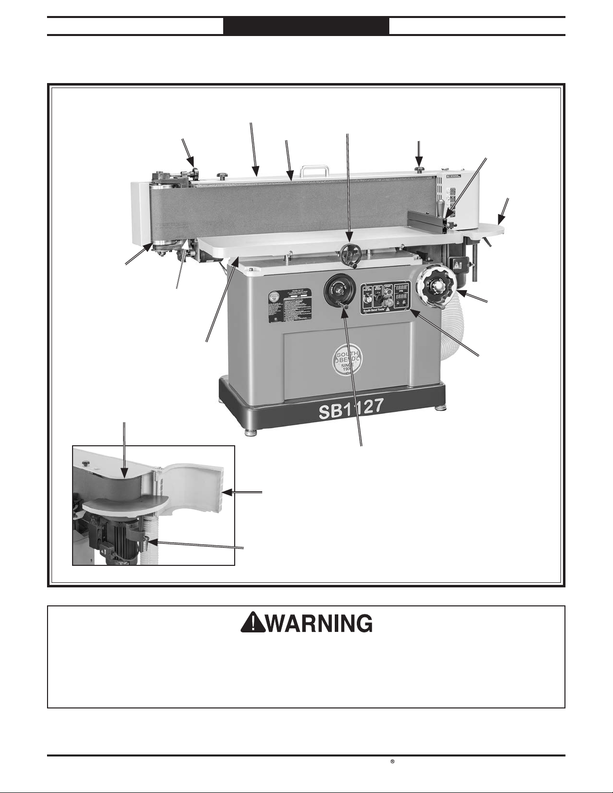
Identification
Idler RollerIdler Roller
Tracking Tracking
KnobKnob
Sanding BeltSanding Belt
Main TableMain Table
Belt GuardBelt Guard
PlatenPlaten
Table Clearance Table Clearance
HandwheelHandwheel
Belt Guard Belt Guard
LockLock
(1 of 2)(1 of 2)
Miter StopMiter Stop
End TableEnd Table
Platen Tilt Platen Tilt
HandwheelHandwheel
Control PanelControl Panel
Drive RollerDrive Roller
Main Table Height Main Table Height
HandwheelHandwheel
Drive RollerDrive Roller
DoorDoor
End TableEnd Table
HeightHeight
Lock HandleLock Handle
For Your Own Safety Read Instruction Manual Before Operating Sander
a) Wear eye protection.
b) Support workpiece with miter gauge, backstop, or worktable.
c) Maintain 1⁄16" maximum clearance between table and sanding belt.
d) Avoid kickback by sanding in accordance with the directional arrows.
-3-
Page 6
South Bend Tools
Model SB1127
INTRODUCTION
For Machines Mfd. Since 11/23
Description of Controls & Components
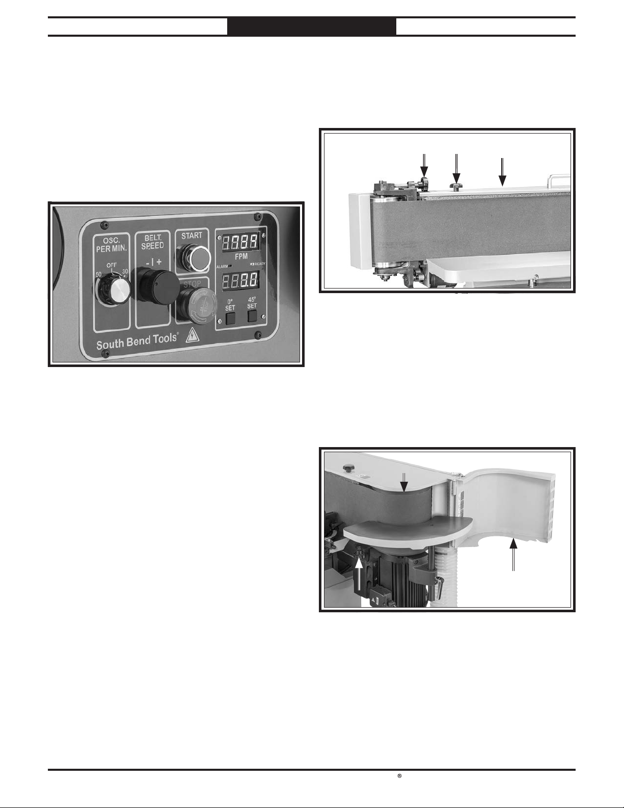
Refer to Figures 1–7 and the following
descriptions to become familiar with the basic
controls and components used to operate this
machine.
Control Panel
DD
CC
AA
BB
II
EE
FF
GG
HH
I. STOP Button: Stops machine and prevents
it from starting. To reset, twist button
clockwise until it pops out.
Sanding Belt
JJ
KK
Figure 2. Sanding belt adjustment and access
components.
J. Tracking Knob: Adjusts sanding belt
tracki n g.
LL
Figure 1. Control panel components.
A. Oscillation Dial: Turns sanding belt
oscillation ON and adjusts oscillations
between 30–50 oscillations per minute.
B. Sanding Belt Speed Dial: Adjusts sanding
belt speed between 1050–4250 feet per
minute.
C. START Button: Starts motor.
D. Sanding Belt Speed Digital Readout:
Displays current sanding belt speed in feet
per minute (FPM).
E. ALARM Indicator: Illuminates when VFD
fault occurs. ALARM indicates that machine
power reset or VFD troubleshooting is
required.
F. READY Indicator: Illuminates when VFD is
operating correctly.
K. Belt Guard Lock Knob (1 of 2): Secures belt
guard.
L. Belt Guard: Opens and closes to allow for
sanding belt replacement and maintenance.
MM
NN
OO
Figure 3. Drive roller and access door.
M. Drive Roller: Provides curved sanding
surface for contour sanding.
G. Platen Tilt Digital Readout: Displays current
platen tilt angle.
H. 0°/45° Set Buttons: Sets platen tilt digital
readout to 0°/45°.
-4-
N. Drive Roller Door: Opens to allow for contour
sanding on end table.
O. Drive Roller Door Lock Knob: Secures drive
roller door.
Page 7
South Bend Tools
For Machines Mfd. Since 11/23 Model SB1127
INTRODUCTION
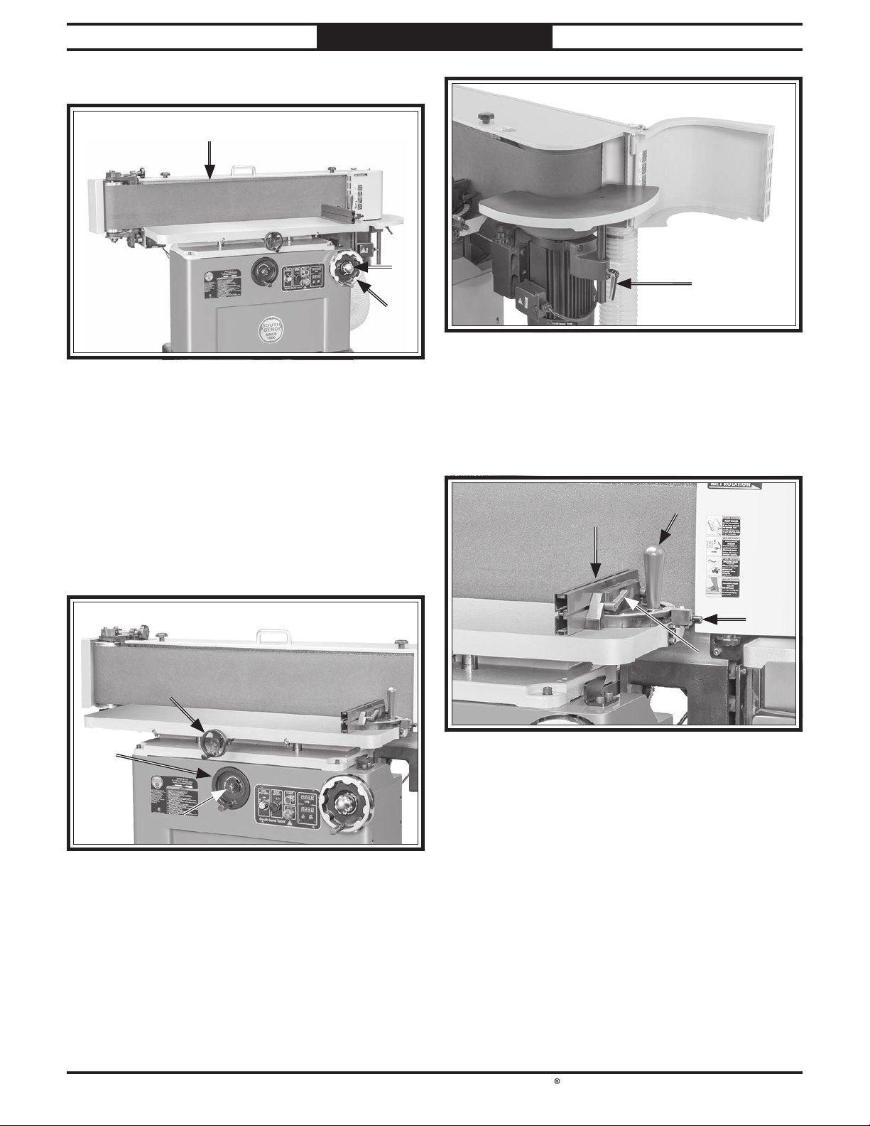
Platen
PP
QQ
VV
RR
Figure 6. End table height lock handle.
Figure 4. Platen adjustment components.
P. Platen: Provides flat surface for end and edge
sanding.
Q. Platen Tilt Lock Knob: Tightens to lock platen
tilt and loosens to adjust tilt.
R. Platen Tilt Handwheel: Manually adjusts
platen tilt angle.
Tables
SS
TT
UU
V. End Table Height Lock Handle: Tightens to
lock end table height and loosens to adjust
end table height.
Miter Stop
XX
WW
YY
ZZ
Figure 7. Miter stop components.
W. Miter Gauge w/Fence: Adjusts from 0°–60° to
support workpiece against sanding belt and
table.
Figure 5. Main table adjustment components.
S. Table Clearance Handwheel: Adjusts
distance between main table and platen.
T. Main Table Height Handwheel: Adjusts main
table height.
U. Main Table Height Lock Knob: Tightens to
lock table height and loosens to adjust height.
X. Miter Gauge Lock Knob: Tightens to lock
miter gauge angle and loosens to adjust miter
gauge angle.
Y. Angle Index Pin: Adjusts miter gauge angle
when turned and stops gauge at 0°, 30°, and
45° for quick adjustments.
Z. Fence Lock Handle (1 of 2): Tightens to lock
fence position and loosens to adjust fence.
-5-
Page 8

South Bend Tools
Model SB1127
Model SB1127
INTRODUCTION
For Machines Mfd. Since 11/23
Product Specifications
P.O. Box 2027, Bellingham, WA 98227 U.S.A.
PHONE: (360) 734-1540 •
www.southbendtools.com
9" x 1381/2" VariableSpeed Oscillating Edge
Sander
Product Dimensions
Weight.............................................................................................................................................................
Width (side-to-side) x Depth (front-to-back) x Height..................................................................... 76 x 40 x 46 in.
Footprint (Length x Width)....................................................................................................................... 39 x 20 in.
Shipping Dimensions
Type............................................................................................................................................................. Wood Box
Content..........................................................................................................................................................
Weight.............................................................................................................................................................
Length x Width x Height................................................................................................................... 81 x 31 x 51 in.
Must Ship Upright................................................................................................................................................ Yes
© South Bend Tools
661 lbs.
Machine
811 lbs.
Electrical
Power Requirement......................................................................................................... 230V, Single-Phase, 60 Hz
Full-Load Current Rating....................................................................................................................................
Minimum Circuit Size..........................................................................................................................................
Connection Type..................................................................................................................................... Cord & Plug
Power Cord Included............................................................................................................................................. Yes
Power Cord Length.......................................................................................................................................... 120 in.
Power Cord Gauge.........................................................................................................................................
Plug Included........................................................................................................................................................
Included Plug Type.............................................................................................................................................. 6-20
Switch Type.......................................................................................................................................... Push Buttons
Inverter (VFD) Type.................................................................................................................... Delta VFD-ME300
Inverter (VFD) Size............................................................................................................................................
Motors
Main
Horsepower...............................................................................................................................................
Phase.................................................................................................................................................... 3-Phase
Amps.......................................................................................................................................................... 8.5A
Speed................................................................................................................................................ 1720 RPM
Type........................................................................................................................................
Power Transfer ......................................................................................................................................
Bearings................................................................................................ Shielded & Permanently Lubricated
TEFC Induction
18A
20A
12 AWG
Yes
3 HP
3 HP
Direct
-6-
Page 9

South Bend Tools
For Machines Mfd. Since 11/23 Model SB1127
Oscillation
Horsepower................................................................................................................................................
Phase............................................................................................................................................
Amps........................................................................................................................................................ 0.27A
Speed.................................................................................................................................................... 44 RPM
Type................................................................................................................................................... DC Brush
Power Transfer .........................................................................................................................................
Bearings................................................................................................
INTRODUCTION
25W
Single-Phase
Gear
Shielded & Permanently Lubricated
Main Specifications
Operation Information
Sanding Belt Speed............................................................................................................... 1100 - 4250 FPM
Sanding Belt Oscillations............................................................................................................... 1/4 - 3/8 in.
Sanding Belt Length....................................................................................................................... 138-1/2 in.
Sanding Belt Width...................................................................................................................................
Sanding Belt Tilt..............................................................................................................................
Table Information
Table Length............................................................................................................................................ 46 in.
Table Width.............................................................................................................................................. 13 in.
Table Thickness................................................................................................................................... 1-3/4 in.
Table Travel.........................................................................................................................................
Floor To Table Height..........................................................................................................
End Table Length.............................................................................................................................. 17-1/4 in.
End Table Width...................................................................................................................................... 12 in.
End Table Thickness........................................................................................................................... 1-3/8 in.
End Table Travel.......................................................................................................................................
33-1/4 - 40-5/8 in.
9 in.
0 - 45 deg.
7-3/8 in.
7 in.
Platen Information
Platen Type............................................................................................................................
Platen Length.................................................................................................................................... 47-5/8 in.
Platen Width............................................................................................................................................ 10 in.
Construction
Table................................................................................................................................................... Cast Iron
Frame...............................................................................................................................................
Base...........................................................................................................................................................
Drive Roller........................................................................................................................................... Rubber
Idler Roller....................................................................................................................................... Aluminum
Miter Block...................................................................................................................................... Aluminum
Paint Type/Finish.................................................................................................................................
Other Related Information
Number of Dust Ports.....................................................................................................................................
Dust Port Size............................................................................................................................................ 4 in.
Belt Release............................................................................................................................... Quick Release
Drive Roller Size........................................................................................................................................ 9 in.
Idler Roller Size.........................................................................................................................................
Graphite Coated
Aluminum
Steel
Enamel
1
5 in.
-7-
Page 10
South Bend Tools
Model SB1127
Operating all machinery and machining equipment can be dangerous or relatively safe depending on
how it is installed and maintained, and the operator's experience, common sense, risk awareness,
working conditions, and use of personal protective equipment (safety glasses, respirators, etc.).
The owner of this machinery or equipment is ultimately responsible for its safe use. This
responsibility includes proper installation in a safe environment, personnel training and usage
authorization, regular inspection and maintenance, manual availability and comprehension,
application of safety devices, integrity of cutting tools or accessories, and the usage of approved
personal protective equipment by all operators and bystanders.
The manufacturer of this machinery or equipment will not be held liable for injury or property
damage from negligence, improper training, machine modifi cations, or misuse. Failure to read,
understand, and follow the manual and safety labels may result in serious personal injury, including
amputation, broken bones, electrocution, or death.
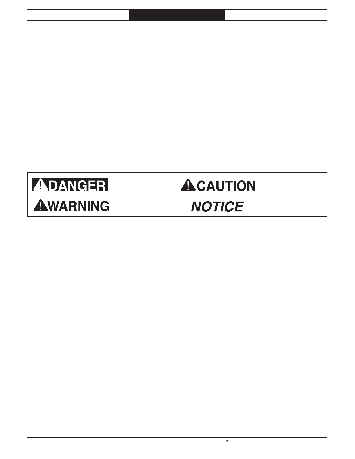
The signals used in this manual to identify hazard levels are as follows:
Owner’s Manual: All machinery and machining
Trained/Supervised Operators Only: Untrained
SAFETY
For Machines Mfd. Since 11/23
Understanding Risks of Machinery
Death or catastrophic
harm WILL occur.
Death or catastrophic
harm COULD occur.
Moderate injury or fi re
MAY occur.
Machine or property
damage may occur.
Basic Machine Safety
equipment presents serious injury hazards
to untrained users. To reduce the risk of
injury, anyone who uses THIS item MUST
read and understand this entire manual
before starting.
Personal Protective Equipment:
servicing this item may expose the user
to fl ying debris, dust, smoke, dangerous
chemicals, or loud noises. These hazards
can result in eye injury, blindness, longterm respiratory damage, poisoning,
cancer, reproductive harm or hearing loss.
Reduce your risks from these hazards
by wearing approved eye protection,
respirator, gloves, or hearing protection.
Operating or
users can seriously injure themselves
or bystanders. Only allow trained and
properly supervised personnel to operate
this item. Make sure safe operation
instructions are clearly understood. If
electrically powered, use padlocks and
master switches, and remove start switch
keys to prevent unauthorized use or
accidental starting.
Guards/Covers:
moving parts during operation may cause
severe entanglement, impact, cutting,
or crushing injuries. Reduce this risk by
keeping any included guards/covers/doors
installed, fully functional, and positioned
for maximum protection.
Accidental contact with
-8-
Page 11

South Bend Tools
For Machines Mfd. Since 11/23 Model SB1127
Entanglement: Loose clothing, gloves, neckties,
Chuck Keys or Adjusting Tools: Tools used to
SAFETY
jewelry or long hair may get caught in
moving parts, causing entanglement,
amputation, crushing, or strangulation.
Reduce this risk by removing/securing
these items so they cannot contact moving
parts.
Mental Alertness: Operating this item with
reduced mental alertness increases the
risk of accidental injury. Do not let a
temporary influence or distraction lead
to a permanent disability! Never operate
when under the influence of drugs/alcohol,
when tired, or otherwise distracted.
Safe Environment:
powered equipment in a wet environment
may result in electrocution; operating near
highly fl ammable materials may result in a
fi re or explosion. Only operate this item in
a dry location that is free from fl ammable
materials.
Electrical Connection: With electrically
powered equipment, improper connections
to the power source may result in
electrocution or fire. Always adhere to
all electrical requirements and applicable
codes when connecting to the power
source. Have all work inspected by a
qualified electrician to minimize risk.
Disconnect Power: Adjusting or servicing
electrically powered equipment while it
is connected to the power source greatly
increases the risk of injury from accidental
startup. Always disconnect power
BEFORE any service or adjustments,
including changing blades or other tooling.
Operating electrically
adjust spindles, chucks, or any moving/
rotating parts will become dangerous
projectiles if left in place when the
machine is started. Reduce this risk by
developing the habit of always removing
these tools immediately after using them.
Work Area:
the risks of accidental injury. Only operate
this item in a clean, non-glaring, and welllighted work area.
Properly Functioning Equipment:
maintained, damaged, or malfunctioning
equipment has higher risks of causing
serious personal injury compared to
those that are properly maintained.
To reduce this risk, always maintain
this item to the highest standards and
promptly repair/service a damaged or
malfunctioning component. Always follow
the maintenance instructions included in
this documentation.
Unattended Operation:
equipment that is left unattended while
running cannot be controlled and is
dangerous to bystanders. Always turn the
power OFF before walking away.
Health Hazards: Certain cutting fluids and
lubricants, or dust/smoke created when
cutting, may contain chemicals known to
the State of California to cause cancer,
respiratory problems, birth defects,
or other reproductive harm. Minimize
exposure to these chemicals by wearing
approved personal protective equipment
and operating in a well ventilated area.
Clutter and dark shadows increase
Poorly
Electrically powered
Secure Workpiece/Tooling:
cutting tools, or rotating spindles can
become dangerous projectiles if not
secured or if they hit another object during
operation. Reduce the risk of this hazard
by verifying that all fastening devices are
properly secured and items attached to
spindles have enough clearance to safely
rotate.
Loose workpieces,
Diffi cult Operations:
operations with which you are unfamiliar
increases the risk of injury. If you
experience difficulties performing the
intended operation, STOP! Seek an
alternative method to accomplish the
same task, ask a qualified expert how the
operation should be performed, or contact
our Technical Support for assistance.
Attempting difficult
-9-
Page 12

South Bend Tools
Model SB1127
pull your hands into sanding surface. Firmly
Small workpieces are difficult
respiratory damage, but it is not a substitute
control when sanding force is applied.
SAFETY
For Machines Mfd. Since 11/23
Additional Oscillating Edge Sander Safety
Serious injury or death can occur if fi ngers, clothing, jewelry, or hair get entangled in moving
components. Impact injuries can occur from kickback if workpiece is improperly fed into moving
sanding belt. Serious pinch injuries can occur from touching in-running nip point between table
and sanding surface. Long-term respiratory damage can occur from using sander without proper
use of a respirator. To reduce the risk of these hazards, operator and bystanders MUST completely
heed the hazards and warnings below.
Avoiding Entanglement. Becoming entangled
in moving parts of this machine can cause
pinching and crushing injuries. To avoid
these hazards, DO NOT wear loose clothing,
gloves, or jewelry, and tie back long hair.
Keep all guards in place and secure.
In-Running Nip Points. The gap between moving
sanding belt and fixed table/support
creates a pinch point for fingers or
workpieces; the larger this gap is, the
greater risk of fingers or workpieces getting
caught in it. Minimize this risk by adjusting
table no more than
belt.
Sanding Belt Direction. Feeding workpiece
incorrectly can cause it to be thrown from
machine, striking operator or bystanders, or
causing your hands to slip into the moving
sanding belt. To reduce these risks, only
sand against direction of sanding belt travel,
ensure workpiece is properly supported, and
avoid introducing sharp edges into moving
sanding belt on leading side of workpiece.
Workpiece Support & Hand Placement. Rotating
sanding belt can remove a large amount of
skin quickly, and kickback can occur with
violent force if workpiece is not properly
supported during operation. Always sand
with workpiece firmly against table or
another support device. Never touch moving
sanding belt on purpose.
Workpiece Integrity. Only sand solid workpieces
that can withstand power sanding forces.
Make sure shape of workpiece is properly
supported on table; avoid sanding workpieces
without flat bottom surfaces unless some
type of jig is used to maintain support and
1
⁄
" away from sanding
16
Feeding Workpiece. Forcefully jamming
workpiece into sanding surface could cause
workpiece to be aggressively grabbed and
grasp workpiece in both hands and ease it
into sanding belt using light pressure.
Small Workpieces.
to control and require close support near
sanding surface. Always use a jig or
other holding device when sanding small
workpieces, and keep hands and fingers at
least 2" away from sanding surface.
Workpiece Inspection. Nails, staples, knots, or
other imperfections in workpiece can be
dislodged and thrown from sander at high
rate of speed into operator or bystanders,
or cause damage to sanding belt or
sander. Never try to sand stock that has
embedded foreign objects or questionable
imperfections.
Sanding Belt Condition. Worn or damaged
sanding belt not only produces poor sanding
results, but could fly apart, aggressively
grab workpiece, and throw debris at the
operator. Always inspect sanding belt before
operation and replace if worn or damaged.
Sanding Dust & Dust Collection. Sanding creates
large amounts of dust and flying particles
that can lead to eye injury or respiratory
illness. Reduce risk by wearing approved
eye and respiratory protection when using
sander. Never operate without adequate
dust-collection system in place and running.
Proper dust collection reduces dust in
work area, decreasing risk of long-term
for using a respirator.
-10 -
Page 13
South Bend Tools
For Machines Mfd. Since 11/23 Model SB1127
PREPARATION
Preparation Overview Required for Setup
The purpose of the preparation section is to help
you prepare your machine for operation. The list
below outlines the basic process. Specific steps
for each of these points will be covered in detail
later in this section.
The typical preparation process is as follows:
1. Unpack machine and inventory contents of
box/crate.
Clean machine and its components.
2.
3. Identify acceptable location for machine and
move it to that location.
Level machine using included adjustable
4.
feet.
Assemble loose components and make any
5.
necessary adjustments or inspections to
ensure machine is ready for operation.
Connect machine to power source.
6.
7. Test run machine to make sure it functions
properly and is ready for operation.
The items listed below are required to
successfully set up and prepare this machine for
operation.
For Lifting
• A forklift or other power lifting device (rated
for at least 1050 lbs.).
• Two lifting straps or chains (rated for at
least 1050 lbs.).
For Power Connection
• A power source that meets the minimum
circuit requirements for this machine. (Refer
to the Power Supply Requirements section
for details.)
For Assembly
• Disposable Rags
• Cleaner/Degreaser
• Safety Glasses
• Disposable Gloves
• Calipers or Measuring Tape
• Dust Hose 4"
• Two Hose Clamps 4"
• Dust Collection System
Like all machinery there is potential danger
when operating this machine. Accidents are
frequently caused by lack of familiarity or
failure to pay attention. Use this machine with
respect and caution to decrease the risk of
operator injury. If normal safety precautions
are overlooked or ignored, serious personal
injury may occur.
No list of safety guidelines can be complete.
Every shop environment is different. Always
consider safety first, as it applies to your
individual working conditions. Use this and
other machinery with caution and respect.
Failure to do so could result in serious
personal injury, damage to equipment, or poor
work results.
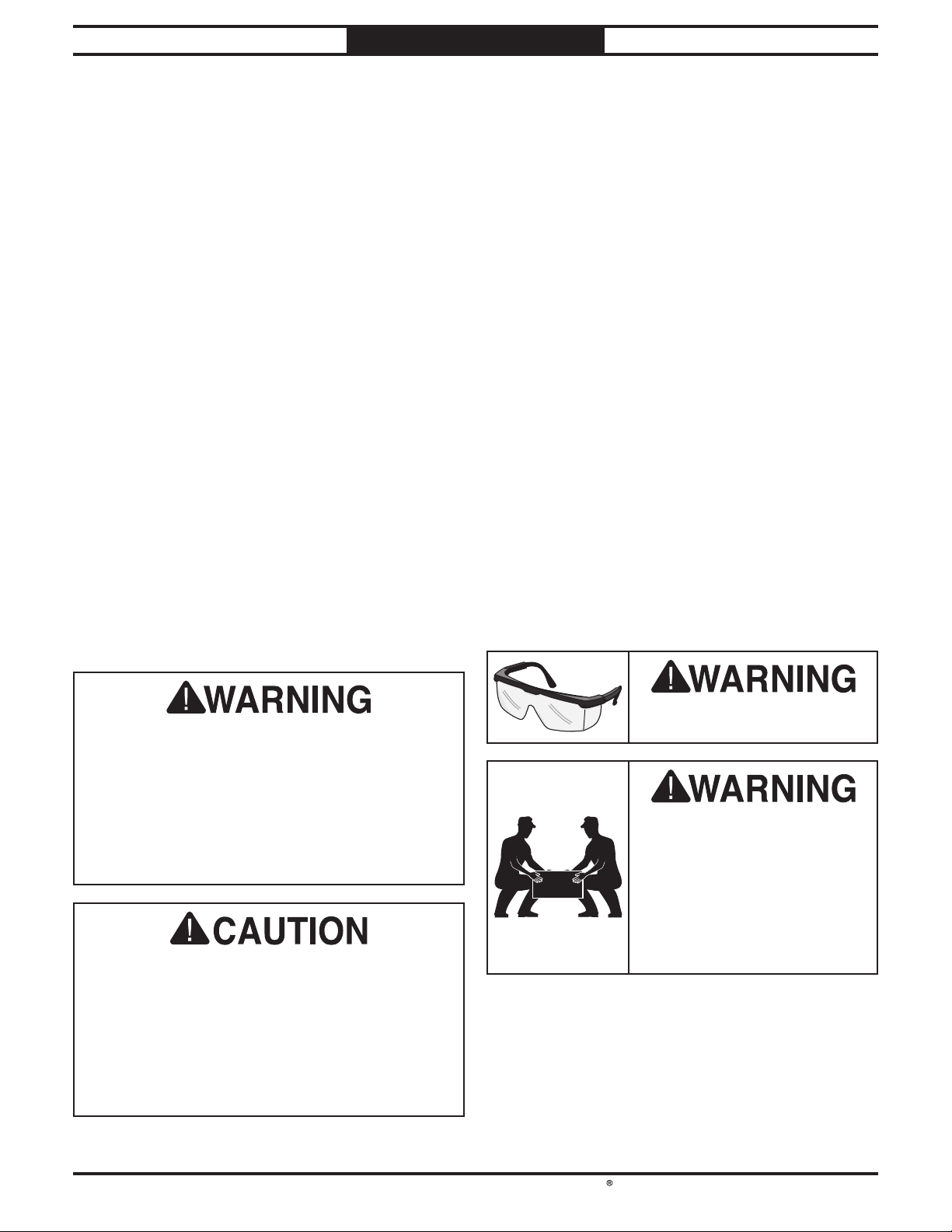
Wear safety glasses during
the entire setup process!
HEAV Y LIF T!
Straining or crushing injury
may occur from improperly
lifting machine. To reduce
this risk, get help from other
people or lifting equipment
rated for weight of this
machine.
-11-
Page 14
South Bend Tools
Model SB1127
Before installing the machine, consider the
availability and proximity of the required power
supply circuit. If an existing circuit does not
meet the requirements for this machine, a new
circuit must be installed.
To minimize the risk of electrocution, fire,
or equipment damage, installation work and
electrical wiring must be done by a
or qualified service personnel in accordance with
applicable electrical codes and safety standards.
The full-load current rating is the amperage
a machine draws at 100% of the rated output
power. On machines with multiple motors, this is
the amperage drawn by the largest motor or sum
of all motors and electrical devices that might
operate at one time during normal operations.
The full-load current is not the maximum
amount of amps that the machine will draw. If
the machine is overloaded, it will draw additional
amps beyond the full-load rating.
If the machine is overloaded for a sufficient
length of time, damage, overheating, or fire may
result—especially if connected to an undersized
circuit. To reduce the risk of these hazards,
avoid overloading the machine during operation
and make sure it is connected to a power supply
circuit that meets the requirements in the
following section.
This machine is prewired to operate on a power
supply circuit that has a verified ground and
meets the following requirements:
Note: The circuit requirements in this manual
are for
machine will be running at a time. If this
machine will be connected to a shared circuit
where multiple machines will be running at the
same time, consult a qualified electrician to
ensure the circuit is properly sized.
A power supply circuit includes all electrical
equipment between the main breaker box or fuse
panel in your building and the incoming power
connections inside the machine. This circuit
must be safely sized to handle the full-load
current that may be drawn from the machine for
an extended period of time. (If this machine is
connected to a circuit protected by fuses, use a
time delay fuse marked D.)
Serious injury could occur if you connect
Power Supply
PREPARATION
For Machines Mfd. Since 11/23
Requirements
Availability
Electrocution or fire may
occur if machine is not
correctly grounded and
attached to the power
supply. Use a qualified
electrician to ensure a safe
power connection.
n electrician
the machine to power before completing the
setup process. DO NOT connect to power until
instructed later in this manual.
Circuit Requirements
Nominal Voltage ........... 208V/220V/230V/240V
............................................................. 60 Hz
Cycle
Phase
Circuit Rating
Plug/Receptacle (included)
................................................ Single-Phase
......................................... 20 Amps
............... NEMA 6-20
Full-Load Current Rating
Full-Load Current Rating at 220V ......... 18 Amps
-12 -
For your own safety and protection of property,
consult an electrician if you are unsure about
wiring practices or applicable electrical codes.
a dedicated circuit—where only one
Page 15
South Bend Tools
For Machines Mfd. Since 11/23 Model SB1127
This machine must be grounded! In the event of
certain types of
grounding provides a path of least resistance
for electric current
electric shock.
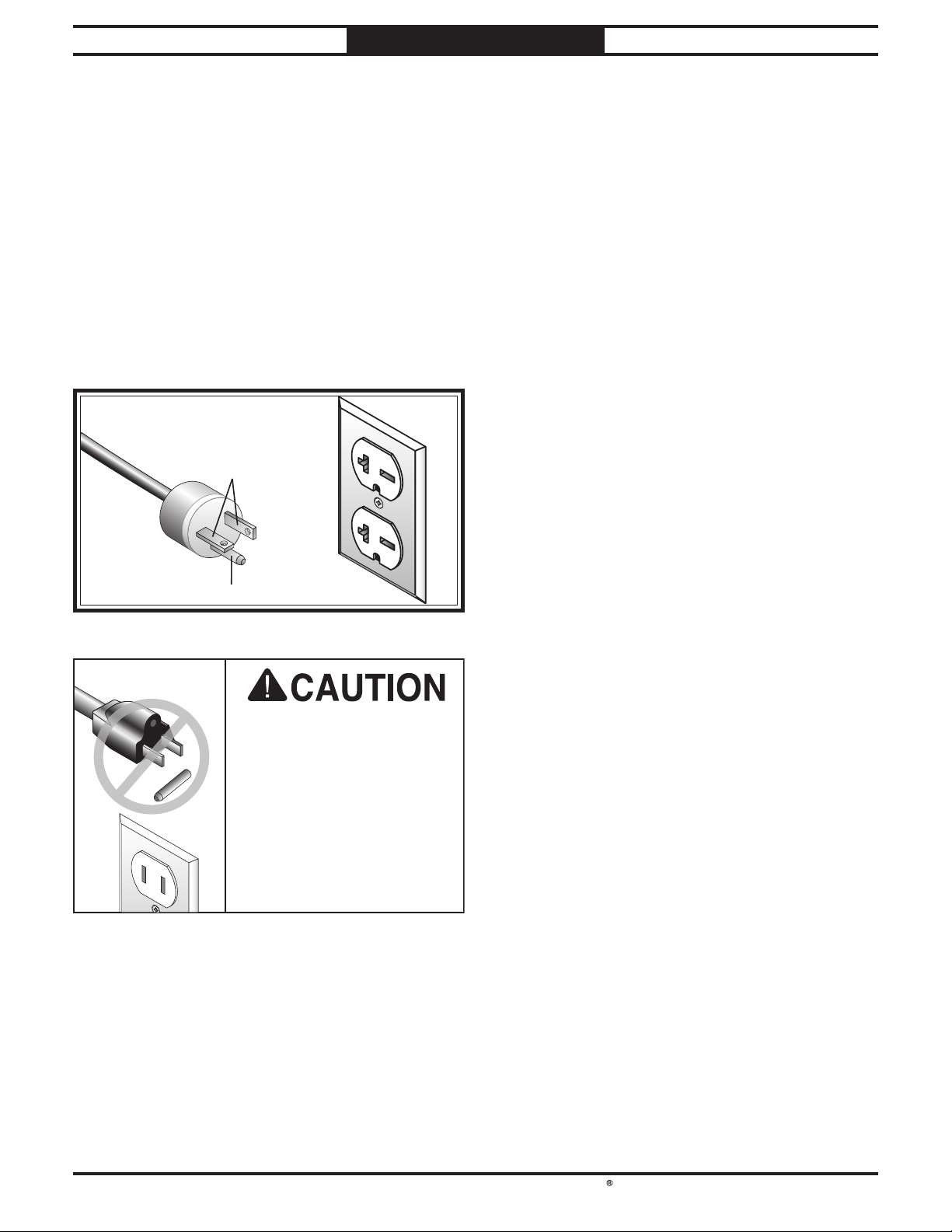
This machine is equipped with a power cord
that has
grounding plug
The plug
receptacle (outlet)
grounded in accordance with all local codes and
ordinances.
Improper connection of the equipmentgrounding wire can result in a risk of electric
shock. The wire with green insulation (with
or without yellow stripes) is the equipmentgrounding wire. If repair or replacement of the
power cord or plug is necessary, do not connect
the equipment-grounding wire to a live (current
carrying) terminal.
Check with an electrician or qualifi ed service
personnel if you do not understand these
grounding requirements, or if you are in doubt
about whether the tool is properly grounded.
If you ever notice that a cord or plug is damaged
or worn, disconnect it from power, and
immediately replace it with a new one.
We do not recommend using an extension cord
with this machine. If you must use one, only
use it if absolutely necessary and only on a
temporary basis.
Extension cords cause voltage drop, which may
damage electrical components and shorten motor
life. Voltage drop increases as the extension cord
size gets longer and the gauge size gets smaller
(higher gauge numbers indicate smaller sizes).
Any extension cord used with this machine must
contain a ground wire, match the required plug
and receptacle listed in the
for the applicable voltage, and meet the following
requirements:
PREPARATION
Grounding Requirements
malfunctions or breakdowns,
in order to reduce the risk of
an equipment-grounding wire and a
(similar to the figure below).
must only be inserted into a matching
that is properly installed and
GROUNDED
6-20 RECEPTACLE
Current Carrying Prongs
6-20 PLUG
Grounding Prong
Figure 8. NEMA 6-20 plug and receptacle.
DO NOT modify the
included plug or use an
adapter if it will not fit your
receptacle. Instead, have a
qualified electrician install
the proper receptacle on a
power supply circuit that
is grounded and meets
the requirements for this
machine.
Extension Cords
Circuit Requirements
Minimum Gauge Size .............................. 12 AWG
Maximum Length (Shorter is Better)
.......... 50 ft.
-13 -
Page 16
South Bend Tools
Model SB1127
This item was carefully packaged to prevent
damage during transport. If you discover any
damage, please immediately call Customer
Service at
need to file a freight claim, so save the containers
and all packing materials for possible inspection
by the carrier or its agent.
PREPARATION
For Machines Mfd. Since 11/23
Unpacking
(360) 734-1540 for advice. You may
Inventory
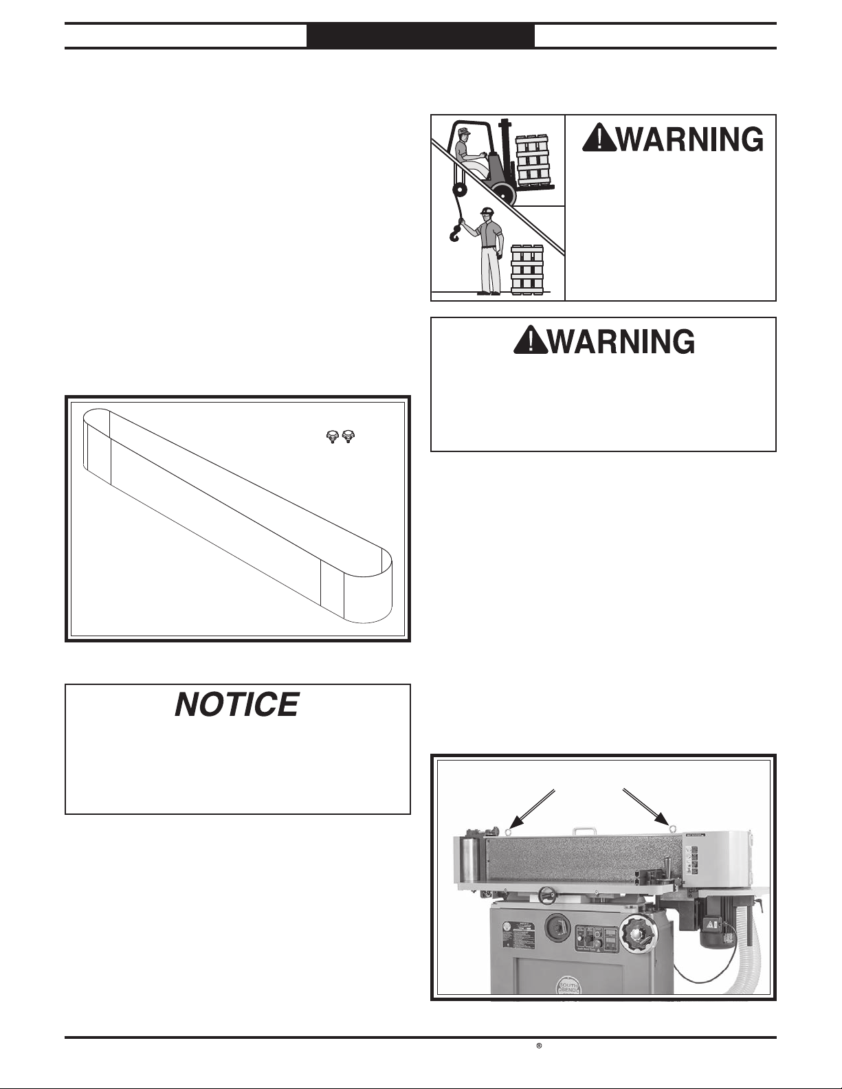
Wood Crate (Figure 9) Qty
A. Machine (Not Shown) ............................. 1
Sanding Belt 9" x 1381⁄2" 120-Grit.............1
B.
Knob Bolts M10-1.5 x 16 ......................... 2
C.
CC
BB
Lifting & Moving
This machine and its
parts are heavy! Serious
personal injury may occur
if safe moving methods are
not used. To reduce the
risk of a lifting or dropping
injury, ask others for help
and use power equipment.
Using only one eye bolt or a different lifting
method could unbalance and tip machine,
which could result in serious injury or
machine damage. To reduce risk of this injury,
be sure to use BOTH eye bolts to lift machine.
Do not attempt to lift or move this machine
without using the proper lifting equipment
(such as a forklift or crane). Each piece of lifting
equipment must be rated for at least 1050 lbs. to
support the dynamic loads that may be applied
while lifting.
Figure 9. Loose inventory.
If you cannot find an item on this list, carefully
check around/inside the machine and
packaging materials. Often, these items get
lost in packaging materials while unpacking or
they are pre-installed at the factory.
-14-
Move the pallet to a suitable location (see
Location on Page 15). Remove any loose small
items from the machine, remove the shipping
brackets securing the machine to the pallet, then
attach lifting straps or chains to the eye bolts
shown in Figure 10. Lift the machine just enough
so the pallet can be removed, then lower the
machine to place it in your desired location.
Eye BoltsEye Bolts
Figure 10. Lifting eye bolt locations.
Page 17
South Bend Tools
For Machines Mfd. Since 11/23 Model SB1127
Weight Load
Additionally, consider the weight of the operator
Physical Environment
The physical environment where your machine
is operated is important for safe operation and
longevity of
machine in a dry environment that is free from
excessive moisture, hazardous
chemicals, airborne abrasives, or extreme
conditions. Extreme conditions for this type of
machinery are generally those where the ambient
temperature
the relative humidity
20–95% (non-condensing); or the environment is
subject to vibration, shocks, or bumps.
Electrical Installation
Place this machine near an existing power
source. Make sure all power cords are protected
from traffic, material handling, moisture,
chemicals, or other hazards. Make sure to leave
access to a means of disconnecting the power
source or engaging a lockout/tagout device.
Lighting
Lighting around the machine must be adequate
enough to perform operations safely. Shadows,
glare, or strobe effects that may distract or
impede the operator must be eliminated.
PREPARATION
Location
parts. For best results, operate this
is outside the range of 41°–104°F;
or flammable
is outside the range of
Refer to the Machine Specifi cations for the
weight of your machine. Make sure that the
surface upon which the machine is placed will
bear the weight of the machine, additional
equipment that may be installed on the machine,
and the heaviest workpiece that will be used.
and any dynamic loading that may occur when
operating the machine.
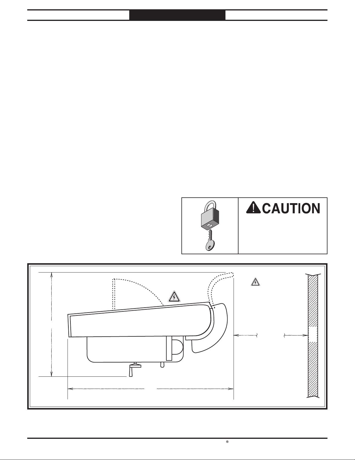
Space Allocation
Consider the largest size of workpiece that will
be processed through this machine and provide
enough space around the machine for adequate
operator material handling or the installation
of auxiliary equipment. With permanent
installations, leave enough space around
the machine to open or remove doors/covers
as required by the maintenance and service
described in this manual.
40"
Figure 11. Minimum working clearances.
Children or untrained
people may be seriously
76"
injured by this machine.
Only install in an access
restricted location.
Electrical
=
Connection
Min. 30"
Wall
-15 -
Page 18
South Bend Tools
Model SB1127
The unpainted surfaces are coated
with a heavy-duty rust preventative that
prevents corrosion during shipment and
The benefi t of this rust preventative is that it
works very well. The downside is that it
time-consuming
Be patient and do a careful job when
removing the rust preventative
spend doing this will reward you with smooth
sliding parts and a better appreciation for the
proper care of
Although there are many ways to successfully
remove the rust preventative, the
process works well in most situations
Before cleaning, gather the following:
• Disposable
• Cleaner/degreaser
• Safety glasses & disposable gloves
Note:
WD•40 can be used to remove rust preventative.
Before using these products, though, test them
on an inconspicuous area of a painted surface to
make sure they will not damage it.
GAS
Order online at
Call 1-800-523-477
PREPARATION
Cleaning & Protecting
For Machines Mfd. Since 11/23
at the factory
to thoroughly remove.
degreasers work extremely well and they
have non-toxic fumes)
Automotive degreasers, mineral spirits, or
the unpainted surfaces.
rags
(certain citrus-based
. The time you
following
storage.
can be
cleaning and
-
.
Avoid chlorine-based solvents, such as
acetone or brake parts cleaner that may
damage painted surfaces. Always follow the
manufacturer’s instructions when using any
type of cleaning product.
Basic steps for removing rust preventative:
1. Put on safety glasses and disposable gloves.
2. Coat all surfaces that have rust preventative
with a liberal amount of your cleaner or
degreaser and let them soak for a few
minutes.
3. Wipe off the surfaces. If your cleaner or
degreaser is effective, the rust preventative
will wipe off easily.
Note: To clean off thick coats of rust
preventative on fl at surfaces, such as beds
or tables, use a PLASTIC paint scraper to
scrape off the majority of the coating before
wiping it off with your rag. (Do not use a
metal scraper or it may scratch the surface.)
4. Repeat Steps 2–3 as necessary until clean,
then coat all unpainted surfaces with a
quality metal protectant or light oil to
prevent rust.
-16-
Gasoline and petroleum
products have low flash
points and can explode
or cause fire if used for
cleaning. Avoid using these
products to remove rust
preventative.
Many cleaning solvents are
toxic if inhaled. Minimize
your risk by only using
these products in a well
ventilated area.
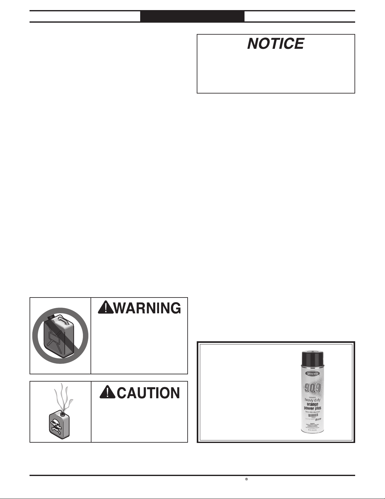
T23692—Orange Power Degreaser
A great product for removing the waxy shipping
grease from the non-painted parts of the
machine during clean up.
www.grizzly.com
OR
7
Figure 12. T23692 Orange Power Degreaser.
Page 19
South Bend Tools
For Machines Mfd. Since 11/23 Model SB1127
PREPARATION
Assembly
The machine must be fully assembled before it
can be operated. Before beginning the assembly
process, see Required for Setup on Page 11
and gather all listed items. To ensure the
assembly process goes smoothly, first clean any
parts that are covered or coated in heavy-duty
rust preventative (if applicable).
Incorrect use of this
machine can result in
death or serious injury.
For your own safety, read
and understand this entire
document before using.
To assemble machine:
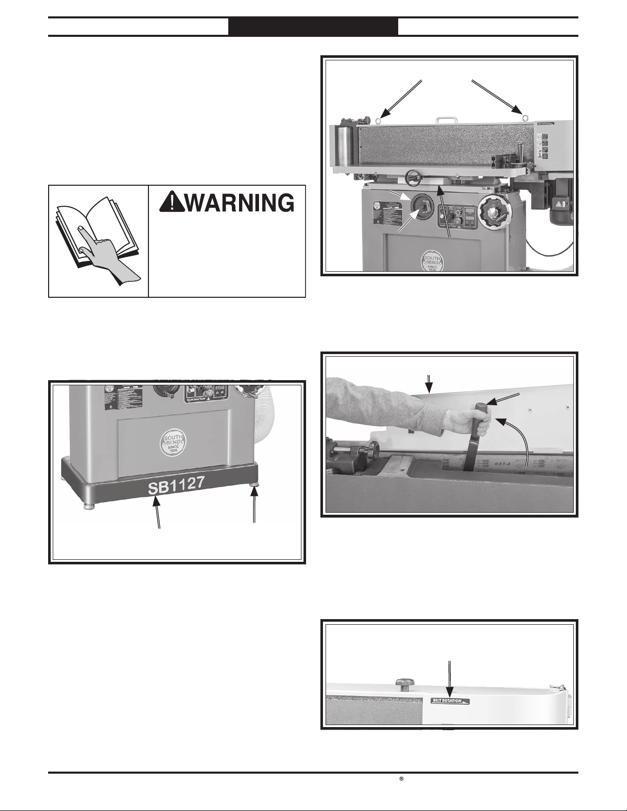
1. Adjust (4) adjustable feet in or out of
machine base (see Figure 13) as needed to
level machine.
Eye BoltsEye Bolts
Main Table Main Table
Height Height
HandwheelHandwheel
Main Table Main Table
Height Lock Height Lock
KnobKnob
Figure 14. Packing and transport removal
5. Open belt guard and move belt tension lever
up and toward idler roller (see Figure 15).
Foam PackingFoam Packing
components.
Belt GuardBelt Guard
Belt Tension Belt Tension
LeverLever
Machine BaseMachine Base
Figure 13. Location of adjustable feet.
2. Remove (2) eye bolts used for lifting (see
Figure 14).
Note: Save eye bolts in case you need to move
machine later.
Loosen main table height lock knob (see
3.
Figure 14).
Turn main table height handwheel clockwise
4.
a few turns to raise table enough so you can
remove foam packing (see Figure 14).
Adjustable Foot Adjustable Foot
(1 of 4)(1 of 4)
Figure 15. Belt guard open and belt tension lever
moved up toward idler roller.
6.
Install and center sanding belt around
rollers, being sure arrows on belt match
arrows of belt rotation on machine (see
Figure 16).
Belt Rotation ArrowBelt Rotation Arrow
(1 of 2)(1 of 2)
Figure 16. Belt rotation arrow.
-17-
Page 20
South Bend Tools
Model SB1127
PREPARATION
For Machines Mfd. Since 11/23
7. Move belt tension lever down, toward drive
roller, to tension sanding belt.
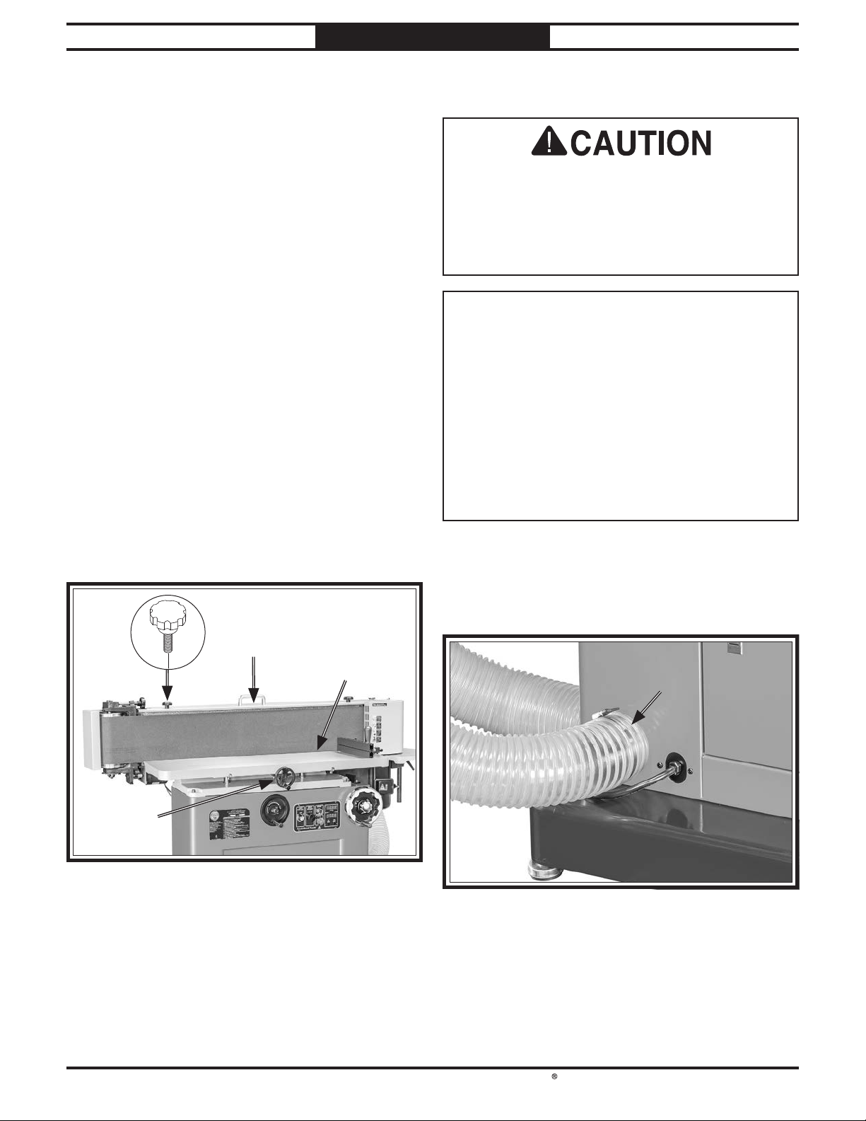
Close belt guard and secure with (2) M10-1.5
8.
x 16 knob bolts, as shown in Figure 17.
Measure clearance between table and sanding
9.
belt.
— If clearance is equal to or less than
1
⁄16" (see Figure 17), and table is not
contacting sanding belt, no further
adjustment is necessary. Proceed to Dust
Collection.
— If clearance is more than 1⁄16", or is
touching sanding belt, proceed to Step 10.
Turn table clearance handwheel (see
10.
Figure 17) until table is within 1⁄16" of
sanding belt, but not touching sanding belt.
— Turn handwheel clockwise to increase
clearance.
Dust Collection
This machine creates a lot of wood chips/
dust during operation. Breathing airborne dust
on a regular basis can result in permanent
respiratory illness. Reduce your risk by
wearing respirator and capturing the dust with
a dust-collection system.
Recommended CFM at Dust Port: 400 CFM
Do not confuse this CFM recommendation with
the rating of the dust collector. To determine
the CFM at the dust port, you must consider
these variables: (1) CFM rating of the dust
collector, (2) hose type and length between the
dust collector and the machine, (3) number of
branches or wyes, and (4) amount of other open
lines throughout the system. Explaining how
to calculate these variables is beyond the scope
of this manual. Consult an expert or purchase a
good dust collection "how-to" book.
— Turn handwheel counterclockwise to
decrease clearance.
x 2
Belt GuardBelt Guard
TableTable
Clearance Clearance
HandwheelHandwheel
Figure 17. Belt guard lock knobs installed and location
of table clearance handwheel.
MaximumMaximum
11
⁄⁄1616" Clearance" Clearance
To connect machine to dust collector:
1. Fit 4" dust hose connected to a dust collector
over rear dust port (see Figure 18), and
secure in place with hose clamp.
RearRear
Dust PortDust Port
Figure 18. Dust hose attached to rear dust port.
Tug hose to make sure it does not come off.
2.
-18 -
Note: A tight fit is necessary and ensures
proper performance during operation.
Page 21
South Bend Tools
For Machines Mfd. Since 11/23 Model SB1127
PREPARATION
Test Run
After all preparation steps have been completed,
the machine and its safety features must be
tested to ensure correct operation. If you
discover a problem with the operation of the
machine or its safety components, do not operate
it further until you have resolved the problem.
Note: Refer to Troubleshooting on Page 39 for
solutions to common problems that may occur.
If you need additional help, contact our Tech
Support at (360) 734-1540.
The test run consists of verifying the following:
• Sanding belt tracks properly and will not
come off rollers during initial startup.
• Motors power up and run correctly.
• STOP button works correctly.
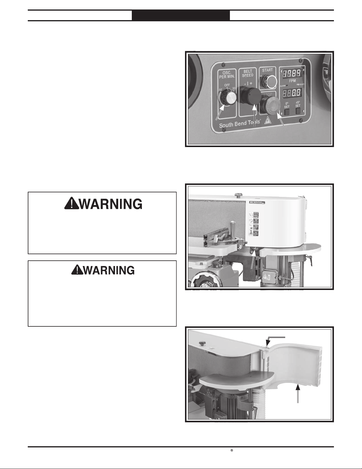
4. Turn oscillation and sanding belt speed dials
all the way counterclockwise (see Figure 19).
Oscillation Oscillation
DialDial
5. Loosen drive roller door lock knob (see
Figure 20).
Sanding Belt Sanding Belt
Speed DialSpeed Dial
Figure 19. Control panel.
STOPSTOP
ButtonButton
Serious injury or death can result from using
this machine BEFORE understanding its
controls and related safety information. DO
NOT operate, or allow others to operate,
machine until the information is understood.
DO NOT start machine until all preceding
setup instructions have been performed.
Operating an improperly set up machine may
result in malfunction or unexpected results
that can lead to serious injury, death, or
machine/property damage.
To test run machine:
1. Clear away all tools and objects used during
preparation and assembly.
Perform Steps 2–3 as described in
2.
Pre-Tracking Sanding Belt on Page
24 to pre-track sanding belt.
Drive Roller Door Drive Roller Door
Lock KnobLock Knob
Figure 20. Location of drive roller door lock knob.
6. Open drive roller door and use latch shown in
Figure 21 to secure it open.
LatchLatch
Press STOP button in (see Figure 19).
3.
Drive Roller DoorDrive Roller Door
Figure 21. Drive roller door secured open.
-19 -
Page 22
South Bend Tools
Model SB1127
PREPARATION
For Machines Mfd. Since 11/23
7. Connect machine to power source. Digital
readouts will illuminate.
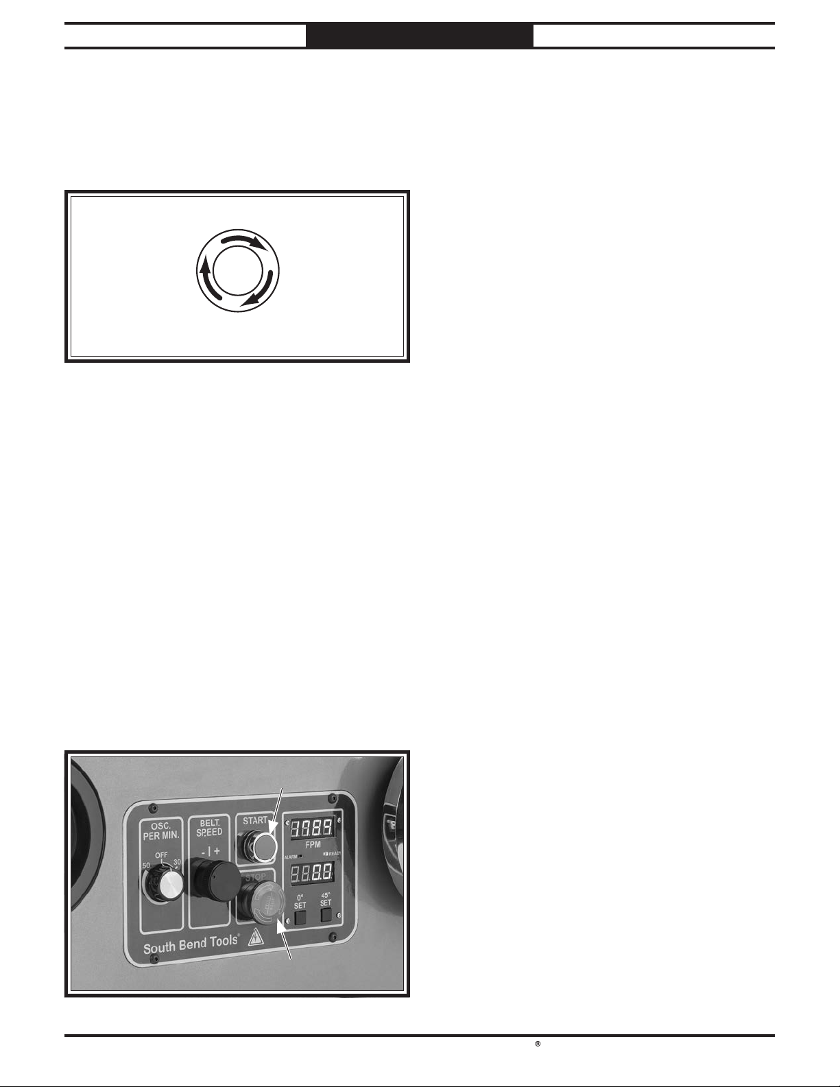
. Twist STOP button clockwise until it springs
8
out (see Figure 22). This resets switch so
machine can start.
I
S
W
T
T
STOP Button
Figure 22. Resetting switch.
. Use START and STOP buttons (see Figure
9
23) to start and immediately stop machine,
while watching how sanding belt tracks on
rollers. "Tracking" refers to sanding belt
positioning on rollers when sanding belt
rotates. When tracking properly, sanding
belt remains centered on rollers as they
rotate.
Start machine and allow it to run while
10.
ensuring sanding belt tracks properly.
Sanding belt motor should run smoothly
and without unusual problems or noises, and
sanding belt MUST rotate in same direction
as arrow of belt rotation on machine.
— If motor runs smoothly and sanding belt
rotates in correct direction, proceed to
Step 11.
— If motor does not run smoothly, or
sanding belt does not rotate in correct
direction, turn machine OFF and
disconnect power. Contact Technical
Service before proceeding.
. Verify speed controls by slowly turning
11
sanding belt speed dial clockwise. Rotate
dial back and forth to test variable-speed
function.
. Slowly turn oscillation dial clockwise so dial
12
is between 30–50 oscillations per minutes
(OPM).
— If sanding belt tracks centered on rollers,
proceed to Step 10.
— If sanding belt does not track centered
on rollers, you must adjust sanding belt
tracking before proceeding to next step
so sanding belt is not damaged. Refer
to Checking/Adjusting Sanding Belt
Tracking on Page 25 and perform Steps
4–6 before continuing.
START ButtonSTART Button
STOP ButtonSTOP Button
Figure 23. Control panel.
Oscillation motor should run smoothly and
without unusual problems or noises.
— If motor runs smoothly, proceed to
Step 13.
— If motor does not run smoothly, turn
machine OFF and disconnect power.
Contact Technical Service before
proceeding.
. Press STOP button to turn machine OFF.
13
. WITHOUT resetting STOP button, try to
14
start machine by pressing START button.
Machine should not start.
— If machine does not start, safety feature
of STOP button is working correctly.
Congratulations! Test run is complete.
— If machine does start, immediately turn it
OFF and disconnect power. Safety feature
of STOP button is NOT working properly
and must be replaced before further using
machine. Contact Technical Support.
-20 -
Page 23
For Machines Mfd. Since 11/23 Model SB1127
The purpose of this overview is to provide
the novice machine operator with a basic
understanding of how the machine is used during
operation, so they can more easily understand
the controls discussed later in this manual.
Note:
it is not intended to be an instructional guide for
performing actual machine operations. To learn
more about specifi c operations and machining
techniques, seek training from people experienced
with this type of machine, and do additional
research outside of this manual by reading "howto" books, trade magazines, or websites.
at all times. Entanglement
tation, or severe crushing
OPERATION
Operation Overview
If you are not experienced with this type
of machine, WE STRONGLY RECOMMEND
that you seek additional training outside of
this manual. Read books/magazines or get
formal training before beginning any projects.
Regardless of the content in this section,
Due to the generic nature of this overview,
To reduce the risk of
serious injury when using
this machine, read and
understand this entire
manual before beginning any
operations.
South Bend Tools will not be held liable for
accidents caused by lack of training.
To complete a typical operation, the operator
does the following:
1. Examines workpiece to make sure it is
suitable for sanding. No extreme bows,
knots, or cracks should exist.
Prepares and trims workpiece as necessary.
2.
3. Installs sanding belt with appropriate grit
for operation.
Adjusts platen tilt and table height as
4.
desired, then adjusts table clearance to allow
maximum of
sanding belt.
1
⁄16" clearance between table and
To reduce risk of eye injury
from flying chips or lung
damage from breathing dust,
always wear safety glasses
and a respirator when
operating this machine.
Keep hair, clothing, and jewelry away from moving parts
can result in death, ampu-
injuries!
Ties back loose hair and clothing, and puts
5.
on safety glasses and respirator. Takes all
other required safety precautions.
Starts sander and dust collecting system.
6.
With both hands, holds workpiece firmly and
7.
flatly against table (and miter stop, if using
main table), and gradually eases workpiece
into sanding belt.
Stops machine.
8.
-21-
Page 24

South Bend Tools
Model SB1127
OPERATION
For Machines Mfd. Since 11/23
Stock Inspection & Requirements
Some workpieces are not safe to sand or may
require modification before they are safe to sand.
Before sanding, inspect all workpieces for the
following:
• Material Type: This machine is intended
for sanding natural and man-made wood
products. This machine is NOT designed
to sand metal, glass, stone, tile, plastics,
drywall, cement backer board, laminate
products, etc.
Sanding improper materials increases risk of
respiratory harm to operator and bystanders
due to especially fine dust inherently created
by all types of sanding operations—even
if a dust collector is used. Additionally,
life of machine and sanding belts will be
greatly reduced (or immediately damaged)
from sanding improper materials or from
exposure to fine dust created when doing so.
• Foreign Objects: Nails, staples, dirt, rocks
and other foreign objects are often embedded
in wood. While sanding, these objects can
become dislodged and tear sanding belt
Always visually inspect your workpiece for
these items. If they cannot be removed, DO
NOT sand the workpiece.
• Wet or "Green" Stock: Sanding wood
with a moisture content over 20% causes
unnecessary clogging and wear on the
sanding belt, increases the risk of kickback,
and yields poor results.
Sanding Tips
• Avoid sanding a workpiece more than is
necessary, since doing so will unnecessarily
decrease sanding belt life and cost you more
money over time.
• Extend the life of sanding belts by regularly
using an abrasive surface cleaner.
• As a rule-of-thumb, sand with progressively
higher grit numbers in increments of 50 or
less.
• Replace sanding belt with a higher grit to
achieve a finer finish (refer to Installing/
Changing Sanding Belts on Page 23).
• Hold the workpiece securely with both
hands. Use the tables/miter stop/back stop
whenever possible to support workpieces. Do
not force the workpiece against the sanding
belt.
• When sanding workpieces with a bow or
crown, place the high point up on the table
to prevent the workpiece from rocking, then
take very light passes.
• Use the full width of the sanding belt by
adjusting the table height or workpiece
position so sanding is not always done in just
one area.
• Make sure belt guard is closed and secured
during operation.
• Sanding belts clog and wear. Change sanding
belt whenever you notice a difference in
sanding quality/performance.
-22-
Moving sanding belt can cause serious
personal injury if it comes in contact with
fingers, hands, or other body parts. Always
support workpiece against table or miter stop
when sanding. Use extreme care to provide
safe distance between sanding belt and any
body part.
Page 25
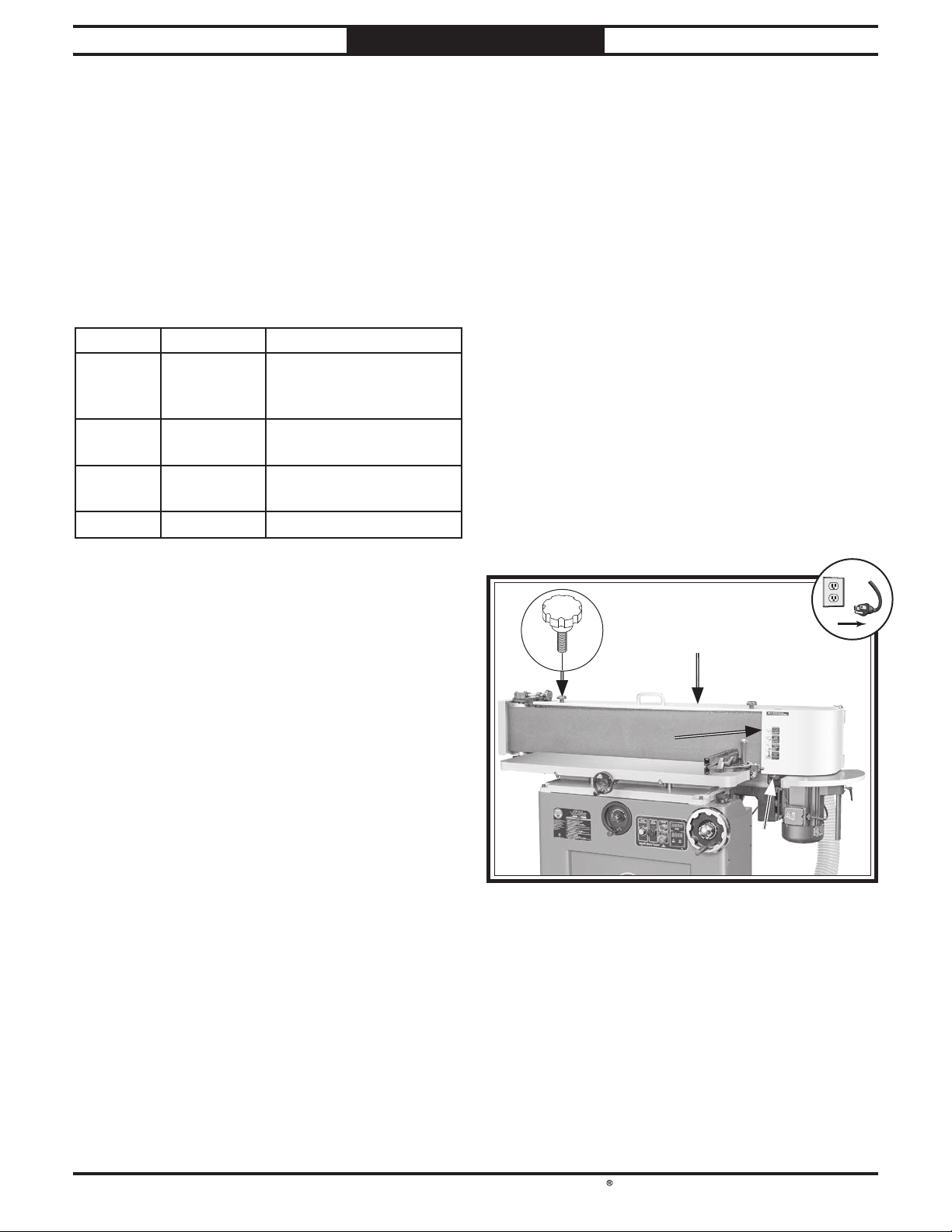
South Bend Tools
For Machines Mfd. Since 11/23 Model SB1127
!
OPERATION
Choosing Sanding Belts
The Model SB1127 uses a 9" x 1381/2" sanding
belt.
We recommend using aluminum-oxide sanding
belts for best results. The grit you choose will
depend on the condition and species of wood, and
the level of finish you wish to achieve.
Grit Class Usage
36 Extra
Coarse
60 Coarse Thickness sanding and
80–100 Medium Removing marks and
120–180 Fine Finish sanding.
The general rule of thumb is to sand a workpiece
with progressively higher grit numbers—in
increments of 50 or less. Avoid skipping grits;
the larger the grit increase at one time, the
harder it will be to remove the scratches from the
previous grit.
Rough sawn boards,
thickness sanding, and
glue removal.
glue removal.
initial finish sanding.
Installing/Changing Sanding Belts
Change the sanding belt when your project
requires a different grit size for quick material
removal or finer finishes. A sanding belt should
be replaced whenever there is a noticeable change
in sanding quality/performance.
Required Sanding Belt Size
To install/change sanding belt:
1. DISCONNECT MACHINE FROM POWER!
Loosen drive roller door lock knob (see
2.
Figure 24) and open drive roller door.
Note: Do not latch door open, it will prevent
Step 3.
Remove (2) belt guard lock knobs (see
3.
Figure 24) and open belt guard.
x 2
Belt GuardBelt Guard
.............. 9" x 1381/2"
Note: A sanding belt with finer than 180-grit will
easily load up or burn workpieces.
Drive RollerDrive Roller
DoorDoor
Drive Roller Door Drive Roller Door
Lock KnobLock Knob
Figure 24. Location of belt guard and drive roller door
components.
-23-
Page 26
South Bend Tools
Model SB1127
OPERATION
For Machines Mfd. Since 11/23
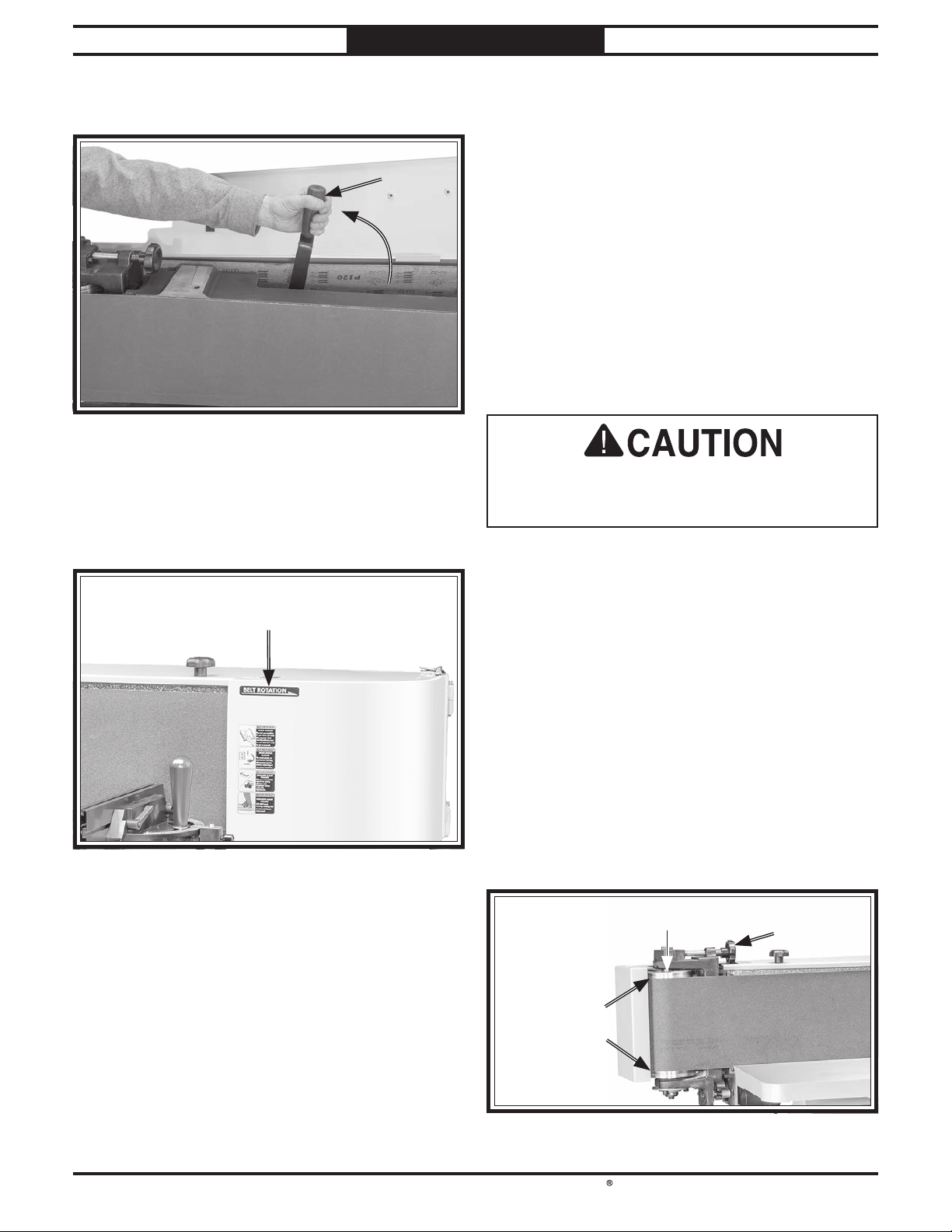
4. Move belt tension lever up and toward idler
roller (see Figure 25).
BeltBelt
Tension Tension
LeverLever
Figure 25. Belt tension lever moved up toward idler
roller.
Remove old sanding belt and replace with
5.
new one, being sure arrows on belt match
arrow of belt rotation on machine (see
Figure 26).
Belt Rotation ArrowBelt Rotation Arrow
(1 of 2)(1 of 2)
Pre-Tracking Sanding Belt
You must perform the following procedure after
installing a sanding belt to ensure that the
sanding belt does not come off or get jammed
against the sanding belt frame.
Items Needed Qty
Protective Gloves ................................. 1 Pair
To pre-track sanding belt:
1. Install desired sanding belt (see Installing/
Changing Sanding Belts on Page 23).
Fingers or other body parts can be quickly
injured if they touch moving sanding surfaces.
To reduce this risk, wear gloves in next step.
Standing in front of sander, push sanding
2.
belt multiple times along platen, so
that it moves in direction of operation
(counterclockwise on rollers, as viewed from
above), then watch how sanding belt tracks
on rollers (see Figure 27).
Figure 26. Belt rotation arrow.
6. Move belt tension lever down, toward drive
roller, to tension sanding belt.
Close belt guard and secure with belt guard
7.
lock knobs.
Sanding belt MUST be pre-tracked before
8.
connecting machine to power. Proceed to
Pre-Tracking Sanding Belt.
Turn tracking adjustment knob clockwise to
3.
adjust tracking upward or counterclockwise
to adjust tracking downward, while
continuing to rotate sanding belt by hand
until sanding belt is centered on rollers (see
Figure 27).
Note: Adjust tracking knob in about 1-turn
increments.
Idler RollerIdler Roller
Equal Spaces Equal Spaces
on Both Sideson Both Sides
Figure 27. Location of tracking knob and example of
sanding belt centered on idler roller.
TrackingTracking
KnobKnob
-24-
Page 27
South Bend Tools
For Machines Mfd. Since 11/23 Model SB1127
Once sanding belt tracks centered on rollers,
4.
proceed to Checking/Adjusting Sanding Belt
Tracking.
Checking/Adjusting Sanding Belt Tracking
The purpose of sanding belt tracking is to make
sure the sanding belt stays centered on the
rollers and platen during sanding operations.
The sanding belt tracking needs to be checked
any time you change or replace the sanding belt.
If the sanding belt tracking is not adjusted
properly, the sanding belt can be damaged and
present a serious safety hazard if it moves off
center of the rollers and throws material when it
contacts the belt guard and other components.
OPERATION
Note: When sanding belt oscillation is turned
ON, sanding belt will oscillate up and down
on rollers, but will ultimately stay centered
on rollers so it does not wander off of rollers.
Do not confuse sanding belt oscillation with
poor sanding belt tracking.
— If sanding belt tracks centered on rollers,
no adjustment is necessary. Proceed to
Step 7.
— If sanding belt does not track centered
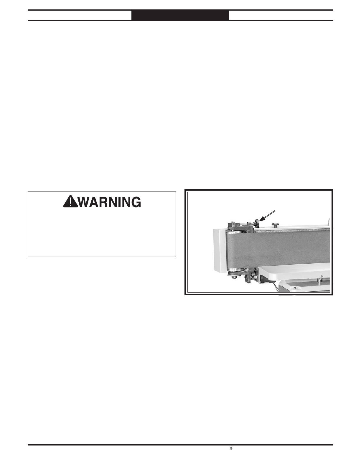
Turn tracking adjustment knob clockwise to
5.
adjust tracking upward or counterclockwise
to adjust tracking downward (see Figure 28).
Note: Adjust tracking knob in about 1-turn
increments.
on rollers, proceed to Step 5.
It is necessary to connect machine to power
to visually track sanding belt tracking. DO
NOT attempt to touch or adjust sanding belt
while machine is connected to power. Failure
to unplug machine before making adjustments
could result in serious personal injury.
To check/adjust sanding belt tracking:
1. Install desired sanding belt (see Installing/
Changing Sanding Belts on Page 23).
Pre-track sanding belt (see Pre-Tracking
2.
Sanding Belt on Page 24).
Connect machine to power.
3.
Press START button, then press STOP
4.
button immediately after. Sander should
run just long enough to observe sanding belt
tracking across rollers and platen.
TrackingTracking
KnobKnob
Figure 28. Location of tracking knob.
6. Repeat Steps 4–5 until sanding belt tracks in
center of rollers.
-25-
Page 28
South Bend Tools
Model SB1127
OPERATION
For Machines Mfd. Since 11/23
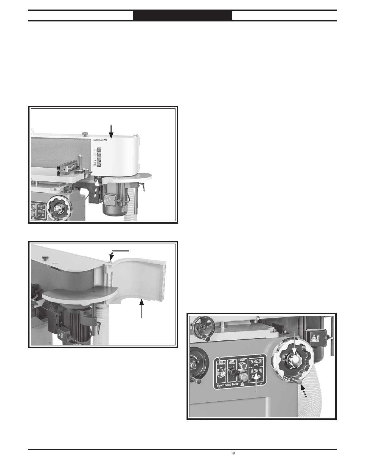
7. Secure drive roller door before proceeding
with operations (see Figures 29–30).
— For sanding on main table, close door
and tighten drive roller door lock knob to
secure.
— For sanding on end table, use latch to
secure door open.
Drive RollerDrive Roller
DoorDoor
Drive Roller Door Drive Roller Door
Lock KnobLock Knob
Adjusting Platen Tilt
The platen adjusts from 0°–45° for beveled
workpieces. If you find that the platen tilt digital
readout is not accurate, press the 0° set button
when the platen is tilted to 0° or the 45° button
when the platen is tilted to 45° to reset it.
Note: Stop bolts stop the platen at 0° and 45°.
Refer to Adjusting Platen Tilt Stops on Page
36 if these stop bolts require adjustment.
When adjusting the platen tilt to an angle other
than 0°, be advised that the existing miter fence
cannot be adjusted to within
platen. Consider using an auxiliary fence that
conforms to the angle of the platen to reduce the
pinch risk this presents.
Adjusting Platen Tilt
1. Connect machine to power, then press STOP
button to disable sanding belt rotation and
prevent accidental machine startup.
1
⁄16" of the entire
Figure 29. Drive roller door secured closed.
LatchLatch
Drive Roller DoorDrive Roller Door
Figure 30. Drive roller door secured open.
Loosen platen tilt lock knob (see Figure 31).
2.
Use platen tilt handwheel to tilt platen until
3.
platen tilt digital readout displays desired
angle (see Figure 31).
— Turn handwheel counterclockwise to
increase angle.
— Turn handwheel clockwise to decrease
angle.
Platen TiltPlaten Tilt
Lock KnobLock Knob
Platen TiltPlaten Tilt
Digital ReadoutDigital Readout
Platen TiltPlaten Tilt
HandwheelHandwheel
-26-
Figure 31. Platen tilt components.
Page 29
South Bend Tools
For Machines Mfd. Since 11/23 Model SB1127
OPERATION
4. Tighten platen tilt lock knob to secure.
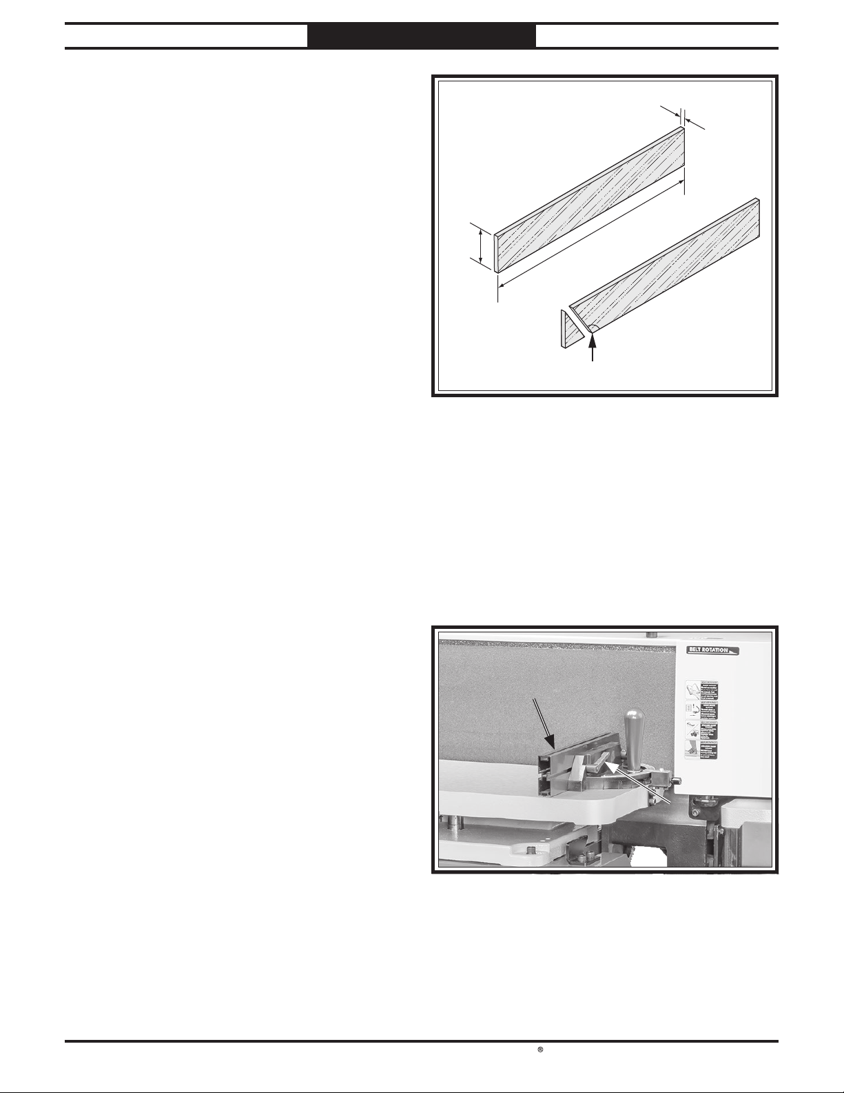
¼"
5. Adjust main table clearance to within 1⁄16"
of sanding belt (see Adjusting Main Table
Clearance on Page 29).
Making an Auxiliary Fence
Any support fixture close to the platen that is
more than
an in-running nip point that could pull fingers or
workpieces into the open space.
A shop-made auxiliary fence will allow you to use
the installed miter stop for operations where the
platen has been tilted, instead of removing it and
installing some other jig or fixture. This fence
should be cut to the same angle as the platen tilt
in order to minimize the risk of pinch points for
fingers or workpieces.
1
⁄16" from the sanding belt results in
2¾"
Figure 32. Auxiliary fence dimensions.
16"
Bevel Angle
Items Needed Qty
Hardwood 1⁄4" x 23⁄4" x 16" .............................1
Marker
Drill
Drill Bits for Countersinking
......................................................1
.........................................................1
............ As Needed
To make an auxiliary fence:
1. Adjust platen tilt to desired bevel angle (see
Adjusting Platen Tilt on Page 26).
Cut piece of hardwood stock at least 1⁄4" thick
2.
to the same height as existing miter fence,
and at least 16" long (see Figure 32).
Note: We recommend cutting hardwood board
oversize, then jointing and planing it to
correct size to make sure board is square and
flat.
Mark and cut desired bevel angle (same as
3.
platen tilt angle) on one edge of board (see
Figure 32).
4. DISCONNECT MACHINE FROM POWER!
5. Adjust main table height as desired for
operation, then adjust main table clearance
1
⁄16" or less (see Adjusting Main Table on
to
Page 29).
Remove (2) miter fence lock handles (see
6.
Figure 33), then remove miter fence from
miter stop.
Miter FenceMiter Fence
Miter Fence Miter Fence
Lock HandleLock Handle
(1 of 2)(1 of 2)
Figure 33. Location of miter fence and miter fence
lock handles.
-27-
Page 30
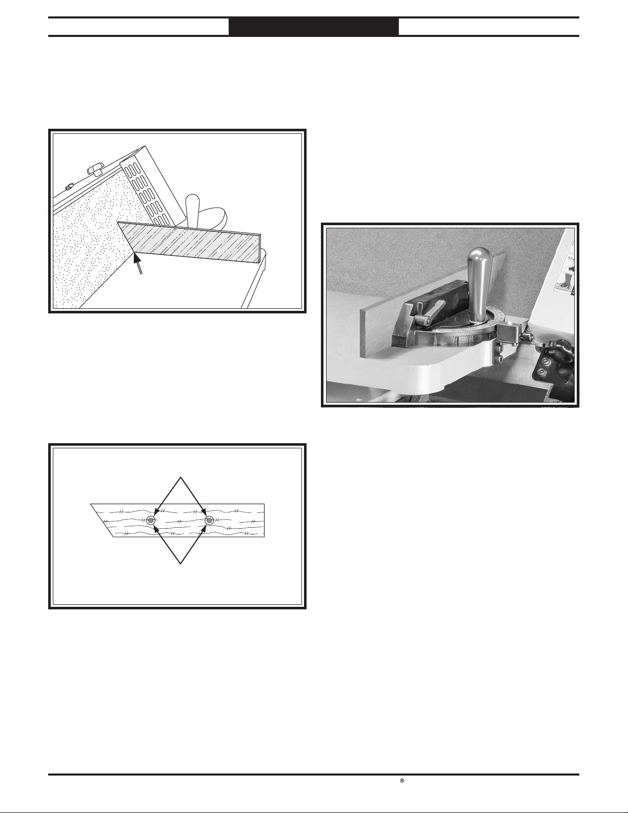
South Bend Tools
Model SB1127
7.
Remove (2) hex bolts from miter fence.
OPERATION
8. Place board in miter fence position against
table so angled edge is within 1⁄16" of sanding
belt (see Figure 34).
Maximum Maximum
11
⁄⁄1616" Gap" Gap
Figure 34. Board in miter fence position.
For Machines Mfd. Since 11/23
Note: Drilling these holes is a two-step
process. Drill first holes all the way through
board with a diameter a little larger than
3
shaft of hex bolt. Drill second holes
⁄16"
through board with a diameter a little larger
than hex bolt head. Second holes must be
deep enough that bolt heads will be well
below surface of board.
11. Secure auxiliary fence to miter stop with (2)
miter fence hex bolts and lock handles (see
Figure 36).
9. Use miter fence lock handle holes to mark (2)
mounting holes in board.
Drill countersunk mounting holes in
10.
auxiliary fence so miter fence hex bolts and
lock handles can be used to secure auxiliary
fence to miter stop (see Figure 35).
Drill two-step holes
Mount with
existing hardware
Figure 35. Example of auxiliary fence mounting holes.
Figure 36. Example of auxiliary fence installed.
-28 -
Page 31
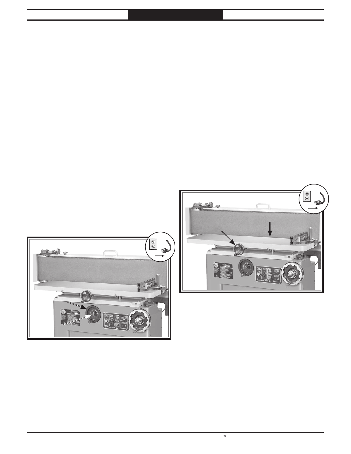
South Bend Tools
For Machines Mfd. Since 11/23 Model SB1127
!
!
OPERATION
Adjusting Main Table
The main table height and clearance are
adjustable to accommodate a wide range of
sanding operations and to prolong sanding belt
life.
Adjusting Main Table Height
Adjust the table up and down when operations
allow it so you can use the full width of the
sanding belt to prevent spot wear.
To adjust main table height:
1. DISCONNECT MACHINE FROM POWER!
2. Loosen main table height lock knob (see
Figure 37).
Adjust main table height handwheel (see
3.
Figure 37) as desired.
— Turn handwheel clockwise to move table
up.
— Turn handwheel counterclockwise to move
table down.
Adjusting Main Table Clearance
The clearance between the main table and
the sanding belt must never exceed
minimize the risk of pinch points for fingers or
workpieces. Check the main table clearance any
time the main table height or the platen tilt has
been adjusted.
To adjust main table clearance:
1. DISCONNECT MACHINE FROM POWER!
2. Adjust main table clearance handwheel (see
Figure 38) until there is a gap of no more
1
than
— Turn handwheel clockwise to increase
— Turn handwheel counterclockwise to
⁄16" between table and sanding belt.
clearance.
decrease clearance.
Main TableMain Table
ClearanceClearance
HandwheelHandwheel
Maximum Maximum
11
⁄⁄1616" Gap" Gap
1
⁄16" to
Main TableMain Table
HeightHeight
HandwheelHandwheel
Main TableMain Table
HeightHeight
Lock KnobLock Knob
Figure 37. Main table height adjustment controls.
Tighten main table height lock knob to
4.
secure.
Main table clearance MUST be adjusted to
5.
within 1⁄16" of sanding belt before platen
sanding. Proceed to Adjusting Main Table
Clearance before proceeding with platen
sanding operation.
Figure 38. Location of main table clearance
handwheel.
-29-
Page 32
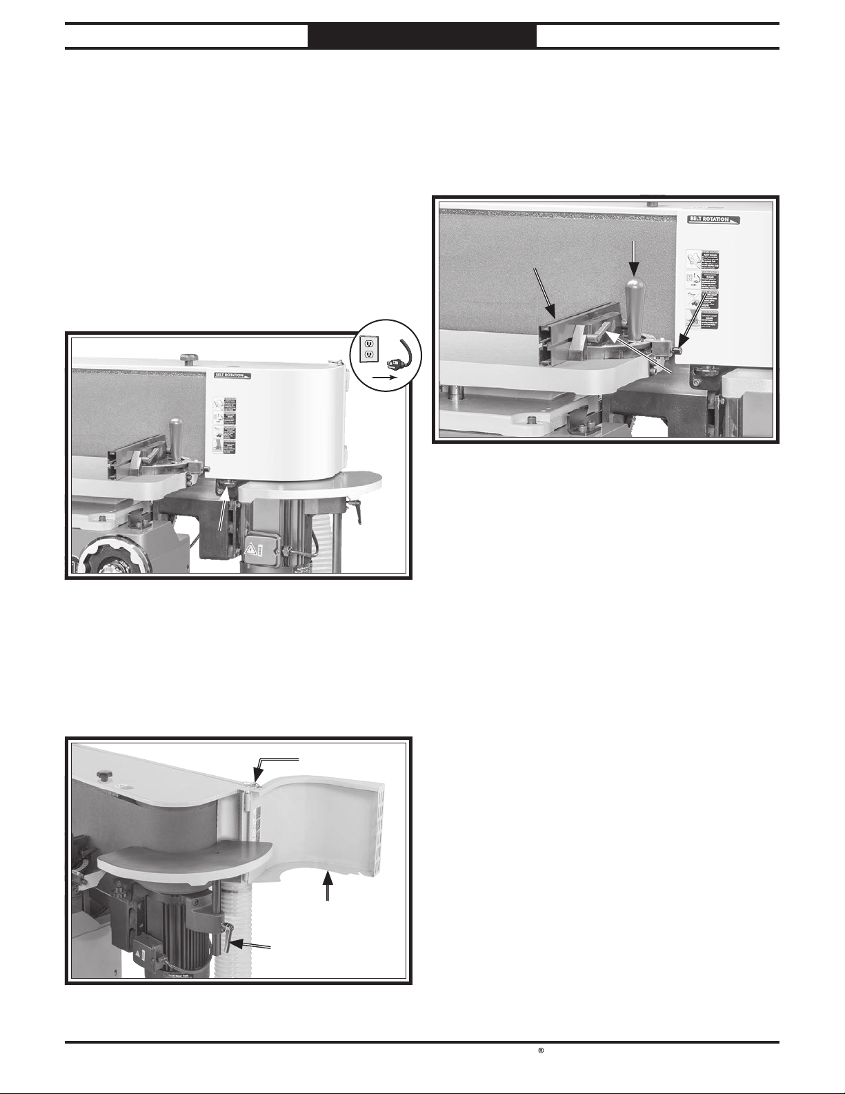
South Bend Tools
Model SB1127
!
OPERATION
For Machines Mfd. Since 11/23
Adjusting End Table Height
The end table has 7" of vertical travel to
accommodate a wide range of workpieces and to
prolong sanding belt life.
To adjust end table height:
1. DISCONNECT MACHINE FROM POWER!
2. Loosen drive roller door lock knob (see
Figure 39).
Drive Roller Door Drive Roller Door
Lock KnobLock Knob
Figure 39. Location of drive roller door lock knob.
Adjusting Miter Stop
The main table has a miter stop that adjusts
between 0°–60° and has an adjustable fence (see
Figure 41) for supporting the workpieces against
the platen when it is perpendicular to the table.
Miter Gauge Miter Gauge
Lock KnobLock Knob
FenceFence
Figure 41. Main table miter stop.
The existing adjustable fence is most effective
when the platen and miter gauge are adjusted to
0°. See Making an Auxiliary Fence on Page 27
to replace the existing fence with a shop-made
one for operations that require a tilted platen
and for more information on the risks angled
operations present.
AngleAngle
IndexIndex
PinPin
Fence Lock Fence Lock
HandleHandle
(1 of 2)(1 of 2)
3. Open drive roller door and use latch shown in
Figure 40 to secure it open.
Loosen end table height lock handle (see
4.
Figure 40), adjust table as desired, then
tighten lock handle to secure.
LatchLatch
Drive Roller DoorDrive Roller Door
End Table Height End Table Height
Lock HandleLock Handle
Figure 40. Drive roller door secured open.
If adjusting the miter stop angle for your
operation requires the existing fence to be
more than
along it's height, consider making a miter angle
auxiliary fence that will minimize the pinch
point similar to the one described in Making an
Auxiliary Fence.
1
⁄16" from the sanding belt anywhere
To adjust miter stop:
1. DISCONNECT MACHINE FROM POWER!
2. Loosen miter gauge lock knob and (2) fence
lock handles (see Figure 41).
Pull angle index pin out and rotate it
3.
until indicator displays desired angle (see
Figure 41).
-30-
Page 33
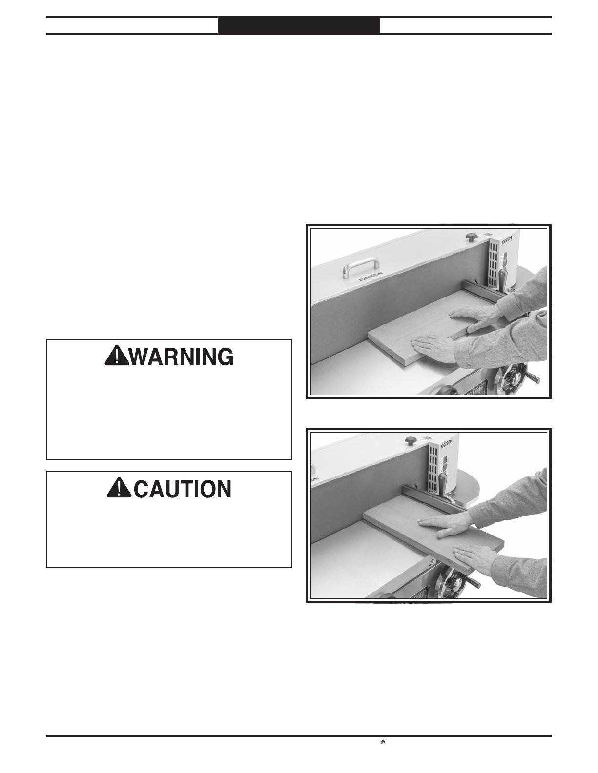
South Bend Tools
For Machines Mfd. Since 11/23 Model SB1127
OPERATION
Note: There are index stop notches at 0°, 30°,
and 45° for quick adjustments.
Tighten miter gauge lock knob to secure
4.
angle setting.
Adjust fence until there is a gap of no more
5.
than 1⁄16" between fence and sanding belt (see
Figure 41 on Page 30).
Tighten (2) fence lock handles to secure
6.
fence.
Edge & End Sanding
Proper use of the oscillating edge sander will
yield excellent sanding results due to the
oscillating movement. Always use the miter stop
to support the workpiece whenever possible.
Edge and end sanding operations are performed
on the main table against the platen.
2. Adjust main table height as desired, then
adjust main table clearance to 1⁄16" or less (see
Adjusting Main Table on Page 29).
Connect machine to power, turn it ON, and
3.
allow it to reach full speed.
Support workpiece against miter stop and
4.
slowly feed workpiece into moving sanding
belt with light, even pressure. Maintain
control of workpiece, as shown in Figures
42–43. DO NOT force workpiece against
sanding belt.
Moving sanding belt can cause serious
personal injury if it comes in contact with
fingers, hands, or other body parts. Make sure
workpiece is always supported against table.
Use extreme care to provide safe distance
between sanding belt and any part of your
body.
If you must feed workpiece into sanding belt
corner first, feed trailing corner first. Feeding
leading corner first could cause sanding belt
to grab workpiece and jerk it out of your
hands.
To edge or end sand:
1. DISCONNECT MACHINE FROM POWER!
Figure 42. Typical edge sanding operation.
Figure 43. Typical end sanding operation.
-31-
Page 34
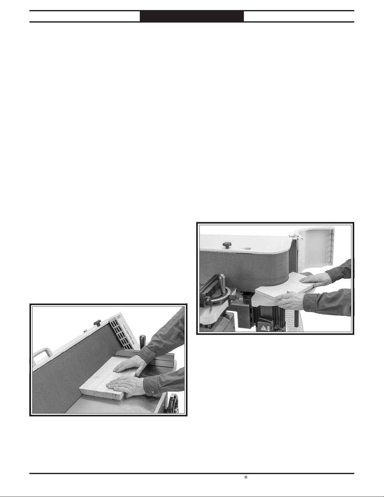
South Bend Tools
Model SB1127
OPERATION
Contour SandingBevel Sanding
For Machines Mfd. Since 11/23
Adjust the platen tilt to match the angle you
wish to sand on a workpiece, then use two hands
to sand the workpiece on the main table against
the platen.
See Making an Auxiliary Fence on Page 27 to
replace the existing fence with a shop-made one
for operations that require a tilted platen and for
more information on the risks angled operations
present.
To bevel sand:
1. Adjust platen tilt to desired bevel angle
of workpiece (see Adjusting Platen Tilt on
Page 26).
DISCONNECT MACHINE FROM POWER!
2.
3. Adjust main table height as desired, then
adjust main table clearance to 1⁄16" or less (see
Adjusting Main Table on Page 29).
Contour sanding operations are performed on the
end table with the workpiece pressing against the
drive roller. Always use two hands to maintain
the best control.
To contour sand:
1. DISCONNECT MACHINE FROM POWER!
2. Open drive roller door and adjust end table
height as desired (see Adjusting End Table
Height on Page 30).
Connect machine to power, turn it ON, and
3.
allow it to reach full speed.
While securely holding workpiece, slowly
4.
feed workpiece into moving sanding belt with
light, even pressure. Maintain control of
workpiece, as shown in Figure 45. DO NOT
force workpiece against sanding belt.
Connect machine to power, turn it ON, and
4.
allow it to reach full speed.
Support workpiece with table (and miter
5.
stop if operation allows), and slowly feed
workpiece into moving sanding belt with
light, even pressure (see Figure 44). DO NOT
force workpiece against sanding belt.
Figure 45. Typical contour sanding operation.
Figure 44. Typical bevel sanding operation.
-32-
Page 35
South Bend Tools
For Machines Mfd. Since 11/23 Model SB1127
!
MAINTENANC E
Maintenance Schedule
Always disconnect
machine from power before
performing maintenance or
serious personal injury may
result.
For optimum performance from your machine,
follow this maintenance schedule and refer to
any specific instructions given in this section.
Ongoing
To minimize your risk of injury and maintain
proper machine operation, shut down the
machine immediately if you ever observe any
of the items below, and fix the problem before
continuing operations:
• Loose mounting bolts.
• Damaged or dirty sanding belt.
• Worn or damaged wires.
• Dirty or unprotected cast-iron surfaces.
• Any other unsafe condition.
Weekly Maintenance
• Clean/vacuum dust buildup from inside
cabinet and belt guard and off of motor.
Cleaning & Protecting
Cleaning the Model SB1127 is relatively easy.
Vacuum excess sawdust and wipe off the
remaining dust with a dry cloth. If any resin has
built up, use a resin dissolving cleaner to remove
it.
Protect the unpainted cast iron table by wiping
them clean after every use—this ensures
moisture from wood dust does not remain on bare
metal surfaces. Keep the tables rust-free with
regular applications of quality metal protectants.
Cleaning Sanding Belts
As sanding belts are used, they will quickly
become "loaded" with sawdust. If not removed,
this sawdust will harden on the abrasive surface,
rendering the sanding belt useless. Routinely
clean the sanding belts with a rubber gum
abrasive surface cleaner .
Always discard worn sanding belts. As abrasive
belts begin to wear, grit will begin to fall off,
causing deep gouges in the workpiece. Glue
used to hold the grit to the sanding belt will
rub off onto the workpiece, causing burns and
interference with final finishing.
Monthly Maintenance
• Lubricate table adjustment components
(Page 34).
Lubricate platen tilt components
•
(Page 35).
Contrary to some beliefs, worn abrasive belts
are not equivalent to next finer grit abrasive.
Discard worn sanding belts and avoid
temptation to use them beyond their usable
life.
-33-
Page 36
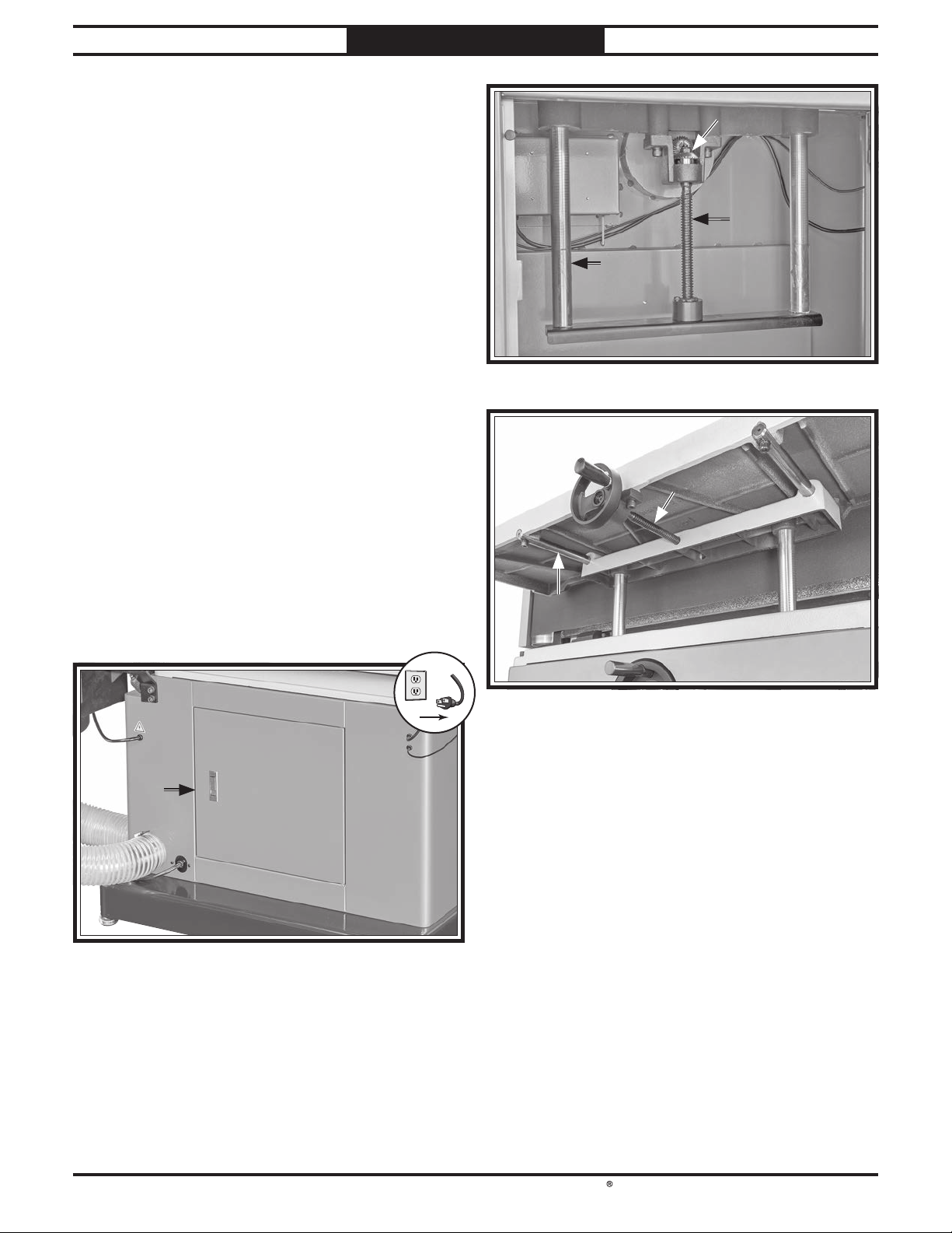
South Bend Tools
Model SB1127
!
MAINTENANC E
For Machines Mfd. Since 11/23
Lubrication
An essential part of lubrication is cleaning the
components before lubricating them. This step
is critical because dust builds up on lubricated
components, which makes them hard to move.
Simply adding more grease to built-up grime
will not result in smooth moving parts. Clean
the components mentioned in this section with
an oil/grease solvent cleaner or mineral spirits
before applying lubrication.
Table Adjustment Components
Items Needed Qty
Disposable Rags ............................. As Needed
Stiff Brushes
Mineral Spirits
T26419 or NLGI#2 Equiv.
SB1365 or ISO 68 Equiv.
To lubricate table adjustment components:
1. DISCONNECT MACHINE FROM POWER!
.............................................2
.............................. As Needed
................. Thin Coat
.................. Thin Coat
Bevel GearsBevel Gears
LeadscrewLeadscrew
ColumnColumn
(1 of 2)(1 of 2)
Figure 47. Table height components to lubricate.
LeadscrewLeadscrew
2. Adjust main table as high as it will go and
increase table clearance all the way.
Open rear cabinet door (see Figure 46).
3.
Rear Rear
Cabinet Cabinet
DoorDoor
Figure 46. Location of rear cabinet door.
4. Clean table adjustment leadscrews, columns,
and bevel gears (see Figures 47–48) with
rags, brush, and mineral spirits to remove
grime and old lubrication.
ColumnColumn
(1 of 2)(1 of 2)
Figure 48. Table clearance components to lubricate.
5. Use clean brush to wipe leadscrew and bevel
gear teeth with thin coat of NLGI#2 grease.
Use clean rags to wipe columns with thin
6.
coat of ISO 68 way oil.
Close rear cabinet door.
7.
8. Adjust main table height and clearance
through their full ranges of travel to spread
lubricants and ensure smooth movement.
Main table clearance MUST be adjusted to
9.
within 1⁄16" of sanding belt before operating.
Refer to Adjusting Main Table on Page 29
to adjust clearance.
-34-
Page 37
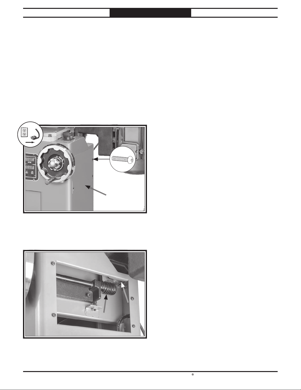
South Bend Tools
For Machines Mfd. Since 11/23 Model SB1127
!
Platen Tilt Components
Items Needed Qty
Hex Wrench 4mm ........................................1
Stiff Brushes
Mineral Spirits
T26419 or NLGI#2 Equiv.
.............................................2
.............................. As Needed
................. Thin Coat
MAINTENANC E
Use clean brush to wipe trunnion and worm
5.
gear teeth with thin coat of NLGI#2 grease.
Adjust platen through its full range of tilt
6.
travel to spread grease and ensure smooth
movement, then install cabinet panel.
To lubricate platen tilt components:
1. Adjust platen tilt to 0°.
DISCONNECT MACHINE FROM POWER!
2.
3. Loosen (4) screws shown in Figure 49 and
remove cabinet panel.
Machine Storage
All machinery will develop serious rust problems
and corrosion damage if it is not properly
prepared for storage. If decommissioning this
machine, prepare the machine as described below
to ensure the machine remains in good condition
for later use.
Preparing Machine for Storage
1. Disconnect all power sources to machine.
x 4
Cabinet Cabinet
PanelPanel
Figure 49. Location of cabinet panel and screws.
4. Clean platen tilt trunnion and worm gear
teeth (see Figure 50) with brush and mineral
spirits to remove grime and old lubrication.
TrunnionTrunnion
Worm GearWorm Gear
2. Remove sanding belt from machine and store
flat in cool, dry area.
Thoroughly clean all unpainted, bare metal
3.
surfaces, then coat them with a lightweight
grease or rust preventative. Take care to
ensure these surfaces are completely covered
but that the grease or rust preventative is
kept off of painted surfaces.
Note: If machine will be out of service for
only a short period of time, use way oil or
good grade of medium-weight machine oil
(not auto engine oil) in place of grease or
rust preventative.
Completely cover machine with tarp or
4.
plastic sheet that will keep out dust and
resist liquid or moisture. If machine will be
stored in/near direct sunlight, use cover that
will block sunlight.
Bringing Machine Out of Storage
1. Clean rust preventative off of machine (refer
to Cleaning & Protecting on Page 16).
Figure 50. Location of platen tilt trunnion and worm
gear.
Install sanding belt.
2.
3. Perform Test Run on Page 19.
-35-
Page 38
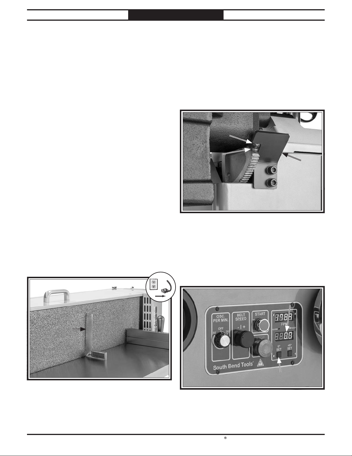
South Bend Tools
Model SB1127
!
SERVICE
For Machines Mfd. Since 11/23
Adjusting Platen Tilt Stops
The Model SB1127 features stop bolts that stop
the platen exactly at 45° and 90° during platen
tilt adjustments. The stops have been set at the
factory and should not require adjustments
unless you notice that beveled workpieces are not
accurate after being sanded.
Note: The platen tilt digital readout reads 0°
when the platen is 90° to the table.
Adjusting 90° Stop Bolt
Items Needed Qty
Open-End Wrenches 13mm ...........................2
90° Square
To adjust 90° stop bolt:
1. Adjust platen tilt to 0°.
.................................................1
— If platen is 90° to table, no adjustment is
required.
— If platen is not 90° to table, proceed to
Step 6.
Loosen jam nut on 90° stop bolt shown in
6.
Figure 52, and adjust 90° stop bolt until
platen is 90° to table when bolt contacts stop
plate.
90° Stop Bolt90° Stop Bolt
Jam NutJam Nut
StopStop
PlatePlate
DISCONNECT MACHINE FROM POWER!
2.
3. Remove sanding belt.
4. Adjust table clearance so table is within 1⁄16"
of platen.
Place 90° square against table and platen, as
5.
shown in Figure 51.
90° Square90° Square
Figure 52. Location of 90° stop bolt and jam nut.
7. Tighten jam nut without turning stop bolt to
secure setting.
Connect machine to power.
8.
9. Press 0° set button to set platen tilt digital
readout display to 0° (see Figure 53).
Platen Tilt Platen Tilt
Digital ReadoutDigital Readout
Figure 51. Checking platen with 90° square.
-36-
0° Set Button0° Set Button
Figure 53. Location of platen tilt calibration
components.
Page 39
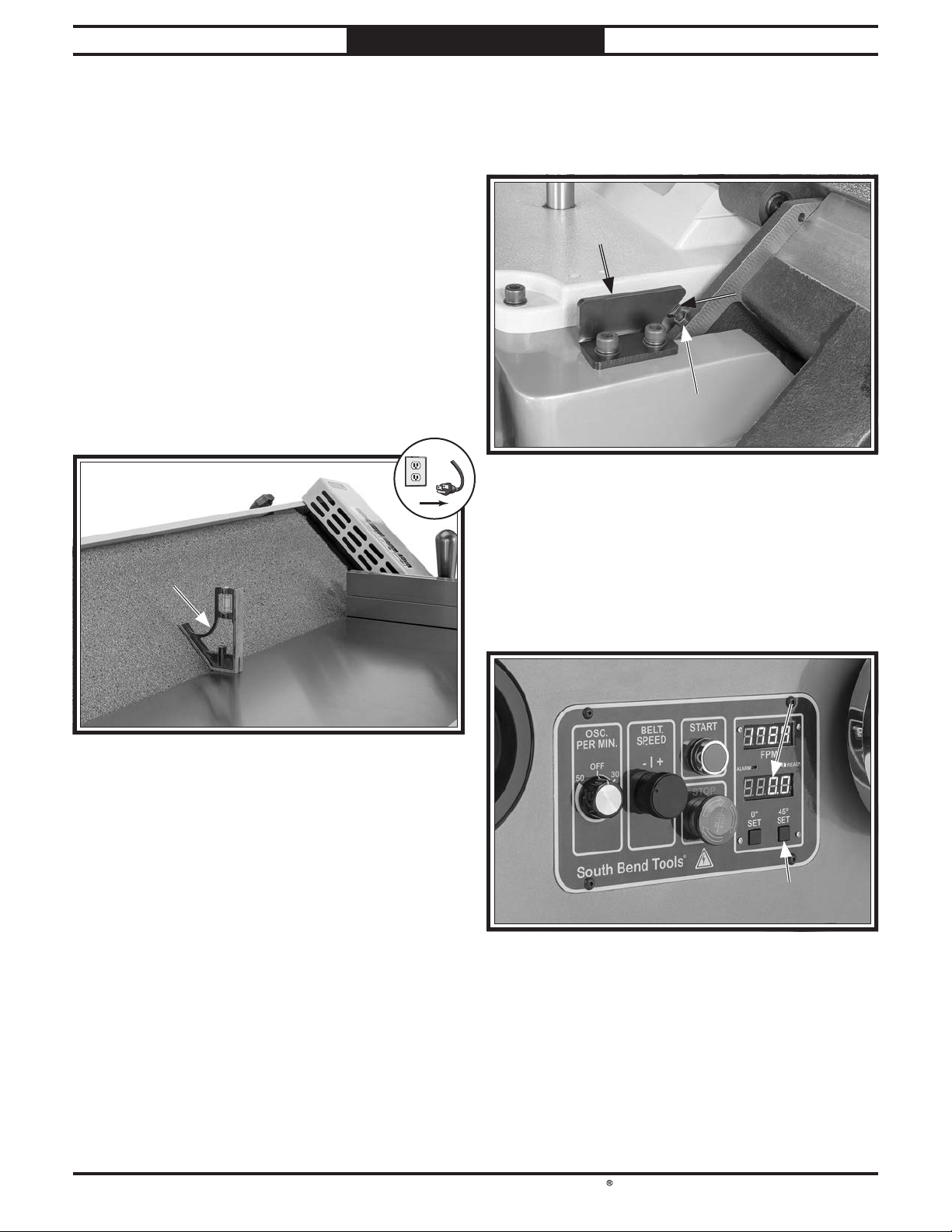
South Bend Tools
For Machines Mfd. Since 11/23 Model SB1127
!
Adjusting 45° Stop Bolt
Items Needed Qty
Open-End Wrenches 13mm ...........................2
45° Square
.................................................1
SERVICE
Loosen jam nut on 45° stop bolt shown in
6.
Figure 55, and adjust 45° stop bolt until
platen is 45° to table when bolt contacts stop
plate.
To adjust 45° stop bolt:
1. Adjust platen tilt to 45°.
DISCONNECT MACHINE FROM POWER!
2.
3. Remove sanding belt.
4. Adjust table clearance so table is within 1⁄16"
of platen.
Stop PlateStop Plate
45° Stop Bolt45° Stop Bolt
Place 45° square against table and platen, as
5.
shown in Figure 54.
45° Square45° Square
Figure 54. Checking platen with 45° square.
— If platen is 45° to table, no adjustment is
required.
— If platen is not 45° to table, proceed to
Step 6.
Jam NutJam Nut
Figure 55. Location of 45° stop bolt and jam nut.
7. Tighten jam nut without turning stop bolt to
secure setting.
Connect machine to power.
8.
9. Press 45° set button to set platen tilt digital
readout display to 45° (see Figure 56).
Platen Tilt Platen Tilt
Digital ReadoutDigital Readout
45° Set Button45° Set Button
Figure 56. Location of platen tilt calibration
components.
-37-
Page 40
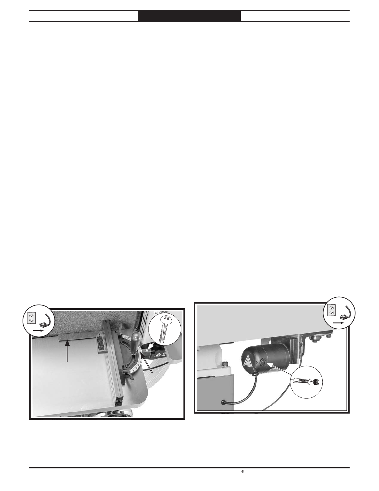
South Bend Tools
Model SB1127
!
!
SERVICE
For Machines Mfd. Since 11/23
Calibrating Miter Stop
This procedure ensures the miter stop angle is
accurate.
Items Needed Qty
90° Square .................................................1
Phillips Head Screwdriver #2
To calibrate miter gauge:
1. Adjust platen tilt to 0°.
DISCONNECT MACHINE FROM POWER!
2.
3. Remove sanding belt.
4. Loosen miter gauge lock knob.
Set one edge of 90° square against platen
5.
and adjust miter gauge angle until the other
edge is flat against miter stop fence (see
Figure 57).
........................1
Replacing Oscillation Motor Brushes
The oscillation motor uses two carbon brushes
to transmit electrical current inside the motor.
These brushes are considered regular "wear
items" or "consumables" that will need to
be replaced during the life of the motor. The
frequency of required replacement is often
related to how much the motor is used and how
hard it is pushed.
Replace the carbon brushes at the same time
when the motor no longer reaches full power, or
when the brushes measure less than
brushes are
If your machine is used frequently, we
recommend keeping an extra set of these
replacement brushes on-hand to avoid any
downtime.
11
⁄16" long).
1
⁄2" long (new
— If miter gauge indicator displays 0° when
miter fence is 90° to platen, no calibration
is required.
— If miter gauge indicator does not display
0° when miter fence is 90° to platen,
proceed to Step 6.
Loosen indicator screw (see Figure 57),
6.
adjust pointer to 0°, then tighten screw.
90° Square90° Square
IndicatorIndicator
Items Needed Qty
Flat Head Screwdriver 1⁄4" .............................1
Replacement Brush Pair (PSB1127056-1)
........1
To replace oscillation motor brushes:
1. DISCONNECT MACHINE FROM POWER!
2. Remove brush caps and worn brushes from
oscillation motor (see Figure 58).
x 2
Figure 57. Miter stop calibration components.
-38-
Figure 58. Location of brush caps on oscillation motor.
3. Replace both motor brushes and install
brush caps.
Page 41

South Bend Tools
For Machines Mfd. Since 11/23 Model SB1127
TROUBLESHOOTING
If you need replacement parts, or if you are unsure how to do any of the solutions given here, feel free
to call us at (360) 734-1540.
Symptom Possible Cause Possible Solution
Machine does not
start, or power
supply breaker
immediately trips
after startup.
Main motor starts,
but oscillation
motor does not.
1.
STOP button depressed.
2.
Incorrect power supply voltage or
circuit size.
3.
Sanding belt speed potentiometer
at fault.
4.
Power supply circuit breaker
tripped or fuse blown.
5.
Motor wires connected incorrectly.
6.
Contactor not energized/at fault.
7.
Wiring broken, disconnected, or
corroded.
8.
START or STOP button at fault.
9.
Circuit board at fault.
10.
VFD at fault.
11.
Main motor or motor bearings at
fault.
1.
Contactor not energized/at fault.
2.
Wiring broken, disconnected, or
corroded.
3.
Motor brushes worn out.
4.
Circuit board at fault.
5.
Oscillation motor or motor bearings
at fault.
1.
Rotate STOP button head to reset.
2.
Ensure correct power supply voltage and circuit size
(Page 12).
3.
Test/replace if at fault.
4.
Ensure circuit is free of shorts. Reset circuit
breaker or replace fuse.
5.
Correct motor wiring connections (Page 42).
6.
Test all legs for power; replace if necessary.
7.
Fix broken wires or disconnected/corroded
connections (Page 42).
8.
Replace button.
9.
Inspect/replace if at fault.
10.
Inspect VFD; replace if at fault.
11.
Replace main motor.
1.
Test all legs for power; replace if necessary.
2.
Fix broken wires or disconnected/corroded
connections (Page 42).
3.
Remove/replace motor brushes (Page 38).
4.
Inspect/replace if at fault.
5.
Replace oscillation motor.
Main motor
stalls or is
underpowered.
Oscillation
motor stalls or is
underpowered.
1.
Workpiece unsuitable for machine.
2.
Circuit board at fault.
3.
Sanding belt speed potentiometer
at fault.
4.
Motor wires connected incorrectly.
5.
Machine undersized for task.
6.
Motor overheated.
7.
Extension cord too long.
8.
Contactor not energized/at fault.
9.
Main motor or motor bearings at
fault.
1.
Circuit board at fault.
2.
Motor brushes worn out.
3.
Motor overheated.
4.
Contactor not energized/at fault.
5.
Oscillation motor or motor bearings
at fault.
1.
Only sand wood/ensure moisture is below 20%
(Page 22).
2.
Inspect/replace if at fault.
3.
Test/replace if at fault.
4.
Correct motor wiring connections (Page 42).
5.
Clean (Page 33)/replace (Page 23) sanding
belt; reduce feed rate/sanding depth.
6.
Clean motor, let cool, and reduce workload.
7.
Move machine closer to power supply; use shorter
extension cord (Page 13).
8.
Test all legs for power; repair/replace if at fault.
9.
Replace main motor.
1.
Inspect/replace if at fault.
2.
Remove/replace motor brushes (Page 38).
3.
Clean motor, let cool, and reduce workload.
4.
Test all legs for power; repair/replace if at fault.
5.
Replace oscillation motor.
-39-
Page 42

South Bend Tools
Model SB1127
TROUBLESHOOTING
For Machines Mfd. Since 11/23
Symptom Possible Cause Possible Solution
Machine has
vibration or noisy
operation.
Sanding belt
speed digital
readout does not
work/display is
incorrect.
Platen tilt digital
readout display is
incorrect.
1.
Motor or component loose.
2.
Drive roller cap screw is missing or
loose.
3.
Stand feet not adjusted correctly.
4.
Motor mount loose/broken.
5.
Motor fan rubbing on fan cover.
6.
Motor bearings at fault.
1.
Sanding belt speed potentiometer is
at fault.
2.
Wiring broken, disconnected, or
corroded.
3.
Digital readout is at fault.
4.
Circuit board is at fault.
1.
Digital readout needs to be reset.
2.
Digital readout was reset when
platen tilt stops were adjusted
incorrectly.
3.
Tilt sensor is adjusted incorrectly.
4.
Wiring broken, disconnected, or
corroded.
5.
Tilt sensor at fault.
6.
Digital readout is at fault.
1.
Replace damaged or missing bolts/nuts or tighten
if loose.
2.
Inspect key. Replace or tighten cap screw if
necessary.
3.
Adjust stand feet to stabilize machine.
4.
Tighten/replace.
5.
Fix/replace fan cover; replace loose/damaged fan.
6.
Test by rotating shaft; rotational grinding/loose
shaft requires bearing replacement.
1.
Test/replace if at fault.
2.
Fix broken wires or disconnected/corroded
connections (Page 42).
3.
Replace digital readout
4.
Inspect/replace if at fault.
1.
Adjust platen perpendicular to table, then press 0°
set button to reset readout.
2.
Adjust platen tilt stops (Page 36).
3.
Adjust tilt sensor position.
4.
Fix broken wires or disconnected/corroded
connections (Page 42).
5.
Replace sensor.
6.
Replace digital readout.
Sanding belt
slaps or vibrates
excessively.
Sanding belt does
not track correctly.
Deep sanding
grooves or scores in
workpiece.
Abrasive grit rubs
off sanding belt
easily.
1.
Incorrect sanding belt tension.
2.
Belt tracking needs adjustment.
3.
Broken/defective sanding belt.
4.
Idler or drive roller is loose.
5.
Weak or broken tension spring.
1.
Belt tracking needs adjustment.
2.
Incorrect sanding belt tension.
3.
Belt damaged, worn, or misshapen.
4.
Oscillation sensor at fault.
5.
Oscillation motor at fault.
1.
Excessive sanding speed.
2.
Using too coarse of sanding grit.
3.
Workpiece sanded across grain.
4.
Too much pressure against belt.
5.
Workpiece held still for too long.
6.
Graphite pad on platen damaged.
1.
Sanding belt has been stored in an
incorrect environment.
2.
Sanding belt has been folded or
crushed.
1.
Make sure tension lever is engaged (Page 23).
2.
Adjust sanding belt tracking (Page 25).
3.
Replace sanding belt (Page 23).
4.
Tighten idler roller or drive roller.
5.
Replace spring.
1.
Adjust sanding belt tracking (Page 25).
2.
Make sure tension lever is engaged (Page 23).
3.
Replace sanding belt (Page 23).
4.
Replace sensor.
5.
Replace oscillation motor.
1.
Decrease sanding speed.
2.
Use finer grit sanding belt (Page 23).
3.
Sand with workpiece grain.
4.
Reduce pressure on workpiece while sanding.
5.
Do not keep workpiece in one place for too long.
6.
Replace graphite pad.
1.
Replace sanding belt (Page 23). Store sanding
belt in a cool, dry area.
2.
Replace sanding belt (Page 23). Store sanding
belt flat, not folded or bent.
-40-
Page 43

South Bend Tools
For Machines Mfd. Since 11/23 Model SB1127
TROUBLESHOOTING
Symptom Possible Cause Possible Solution
Sanding belt
surfaces clog
quickly or burn.
Burn marks on
workpiece.
Glazed sanding
surfaces.
1.
Excessive sanding speed.
2.
Worn sanding belt.
3.
Too much pressure against belt.
4.
Sanding softwood.
5.
Workpiece has high moisture
content or sap.
6.
Using too fine of sanding grit.
7.
Poor dust collection.
1.
Excessive sanding speed.
2.
Using too fine of sanding grit.
3.
Too much pressure against belt.
4.
Workpiece held still for too long.
5.
Sanding belt loaded with sawdust,
resin, and/or pitch.
1.
Sanding wet stock.
2.
Sanding stock with high pitch/
residue.
3.
Belt worn or filled with pitch/
residue.
1.
Decrease sanding speed.
2.
Replace sanding belt (Page 23).
3.
Reduce pressure on workpiece while sanding.
4.
Use different stock or accept characteristics of
workpiece and plan on cleaning (Page 33)/
replacing belt (Page 23) frequently.
5.
Use different stock or accept characteristics of
workpiece and plan on cleaning (Page 33)/
replacing belt (Page 23) frequently.
6.
Use coarser grit sanding belt (Page 23).
7.
Unclog ducts; close gates to improve suction;
redesign dust collection system.
1.
Decrease sanding speed.
2.
Use coarser grit sanding belt (Page 23).
3.
Reduce pressure on workpiece while sanding.
4.
Do not keep workpiece in one place for too long.
5.
Clean (Page 33) or replace belt (Page 23).
1.
Dry properly before sanding (Page 22).
2.
Use different stock or accept characteristics of
workpiece and plan on cleaning (Page 33)/
replacing belt (Page 23) frequently.
3.
Replace belt (Page 23) or clean pitch/residue
from belt (Page 33).
Workpiece
frequently gets
pulled out of your
hand.
Snake-shaped
marks on
workpiece.
Sanding surface
not square when
miter stop is set
to 0°.
Platen tilt
handwheel is hard
to rotate.
Main table height
handwheel is hard
to rotate.
Table clearance
handwheel is hard
to rotate.
1.
Not supporting workpiece properly.
2.
Starting workpiece on a leading
corner.
1.
Sanding belt loaded with sawdust,
resin, and/or pitch.
2.
Sanding belt damaged.
1.
Miter stop not perpendicular to
platen/belt when set to 0°.
1.
Platen tilt trunnion and worm gear
are dirty/need lubrication.
1.
Main table height leadscrew, bevel
gears, and columns are dirty/need
lubrication.
1.
Table clearance leadscrew and
columns are dirty/need lubrication.
1.
Use miter stop to support workpiece.
2.
Start workpiece on a trailing corner.
1.
Clean (Page 33) or replace belt (Page 23).
2.
Replace sanding belt (Page 23).
1.
Calibrate miter stop (Page 38).
1.
Clean and lubricate trunnion and worm gear
(Page 34).
1.
Clean and lubricate leadscrew, bevel gears, and
column (Page 34).
1.
Clean and lubricate leadscrew and columns
(Page 34).
-41-
Page 44
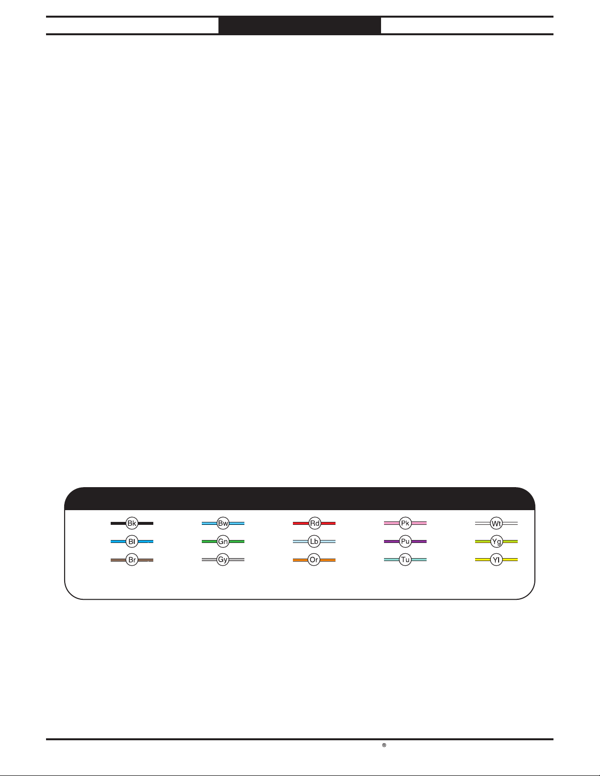
South Bend Tools
Model SB1127
Shock Hazard: It is extremely dangerous to
Wire Connections:
Modifi cations:
Motor Wiring:
junction box.
Circuit Requirements: Connecting the machine
power inverters store an electrical charge for
information included in this section, contact
our Technical Support at (360) 734-1540.
ELECTRICAL
For Machines Mfd. Since 11/23
Electrical Safety Instructions
These pages are accurate at the time of printing. In the constant effort to improve, however, we may
make changes to the electrical systems of future machines. Study this section carefully. If you see
differences between your machine and what is shown in this section, call Technical Support at (360)
734-1540 for assistance BEFORE making any changes to the wiring on your machine.
perform electrical or wiring tasks while the
machine is connected to the power source.
Touching electrifi ed parts will result in
personal injury including but not limited to
severe burns, electrocution, or death. For
your own safety, disconnect machine from
the power source before servicing electrical
components or performing any wiring tasks!
All connections must be
tight to prevent wires from loosening during
machine operation. Double-check all wires
disconnected or connected during any wiring
task to ensure tight connections.
Using aftermarket parts or
modifying the wiring beyond what is shown
in the diagram may lead to unpredictable
results, including serious injury or fi re.
The motor wiring shown in these
diagrams is current at the time of printing,
but it may not match your machine. Always
use the wiring diagram inside the motor
to an improperly sized circuit will greatly
increase the risk of fi re. To minimize
this risk, only connect the machine to a
power circuit that meets the minimum
requirements given in this manual.
Capacitors/Inverters: Some capacitors and
up to 10 minutes after being disconnected
from the power source. To reduce the risk of
being shocked, wait at least this long before
working on capacitors.
Wire/Component Damage: Damaged wires
or components increase the risk of serious
personal injury, fi re, or machine damage. If
you notice that any wires or components are
damaged while performing a wiring task,
replace those wires or components before
completing the task.
Experiencing Diffi culties: If you are
experiencing diffi culties understanding the
BLACK
BLUE
BROWN
NOTICE:
-42-
WIRING DIAGRAM COLOR KEY
BLUE
WHITE
GREEN
G R AY
The photos and diagrams included in this section are best viewed in color. You can
see them in color at www.southbendtools.com.
RED
LIGHT
BLUE
ORANGE
PINK
PURPLE
TURQUIOSE
WHITE
YEL LOW
GREEN
YEL LOW
Page 45
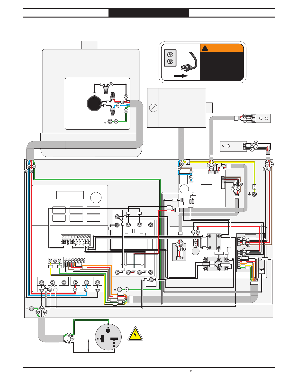
South Bend Tools
For Machines Mfd. Since 11/23 Model SB1127
ELECTRICAL
Wiring Diagram
!
WARNING!
Main Motor 230VAC
3
3
1
2
GND
Oscillation
!
Motor
200VDC
SHOCK HAZARD!
Disconnect power
before working on
wiring.
P3
Tilt Sensor
Circuit Board
TH_Hall2_CT
Oscillation
Sensor
Circuit Board
MH253
VFD
DELTA VFD11AME21ANNAA
MI1
MI2
MI3
MI4
MI1
+10V
ACM
+10V
AVI
ACM
RARBRC
RA RC
R/L1 S /L2 T/L3 U/T1 V/T2 W/T3
L1
L2
GND
AFM
AFM
P3
L2
P2
T2
P3
M+
M-
Control Driver
Circuit Board
AC2
AC1
AC1
L2
P2
A
A
L1
MI5
+24V
+24V
DCM
DCM
DCMMI4
MO1
MCM
PE
AVI
L1/1 L2/3 L3/5 21NC
T1/2 T2/4 T3/6 22NC
GND
AFM
AVI
ACM
+10V
RC
RA
L2
A
Contactor
SDE MA-09
P6
L3
T2T1
T3
B
B
T2
P4
P1
Rly
GND
Oscillation Speed
Circuit Board
EP-VR-CT
B
AC1
VR
VCC
AC2
AC2
B10K
Potentiometer
COSMOS
YIJIA LA36M-40
E3
E4
YIAN KUANG YS-F1
P2
P4
P5
STOP Button
2
3
1
4
E1/S13
21221314X1
S13
X2/S14
S14
START Button
Control Panel
P1
P4
E2
X1
X1
X2
P4
P3
P6
DRO
Circuit Board
+10V
AVI
AFM
RA
RC
GND
ACM
P5
AC2
AC2
AC1
AC1
P6
Ground
Hot
220
VAC
Machine Cabinet
G
6-20 Plug
Hot
-43-
Page 46
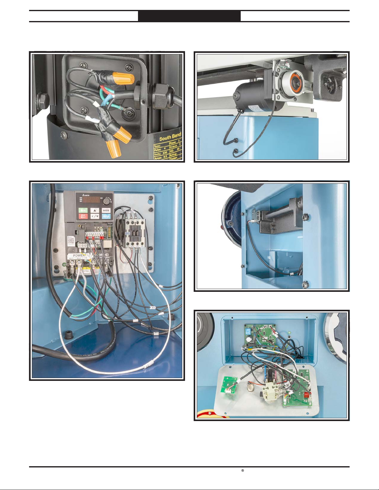
South Bend Tools
Model SB1127
ELECTRICAL
Electrical Components
For Machines Mfd. Since 11/23
Figure 59. Main motor wiring.
Figure 61. Oscillation motor and sensor.
Figure 62. Tilt sensor.
Figure 60. VFD and contactor wiring.
-44-
Figure 63. Control panel wiring.
Page 47
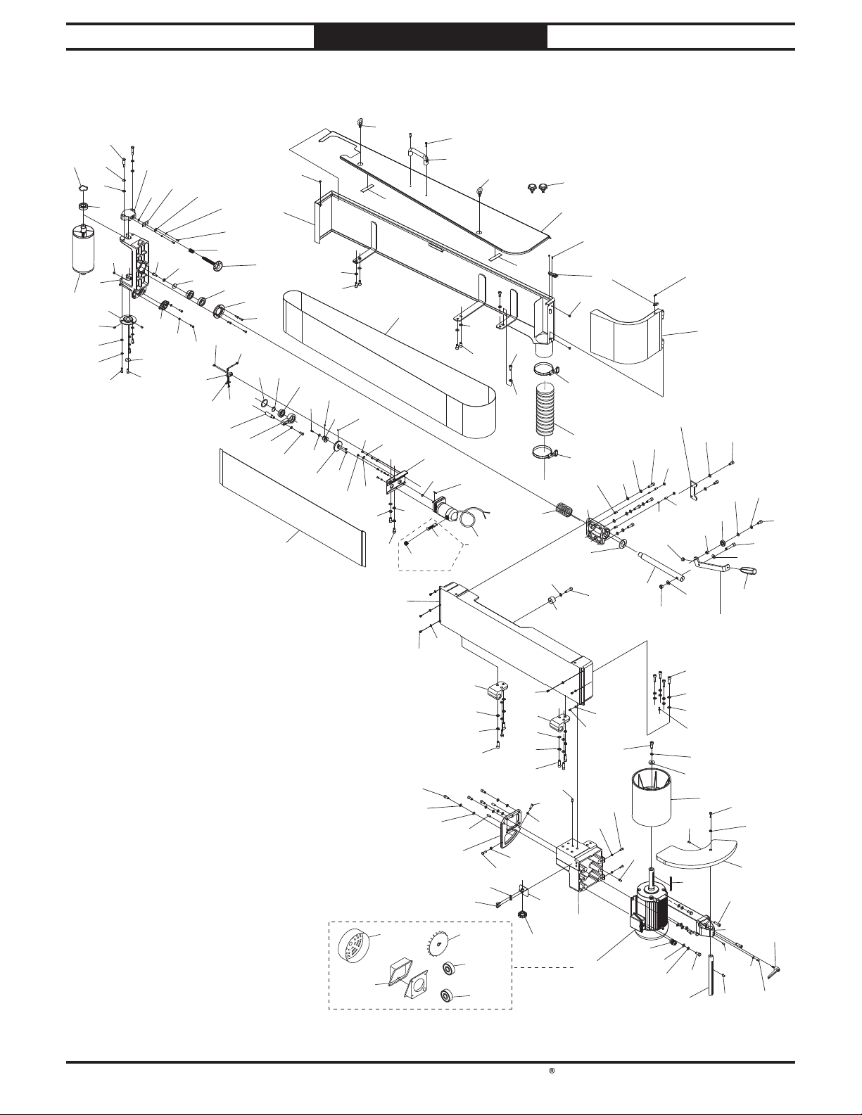
South Bend Tools
For Machines Mfd. Since 11/23 Model SB1127
34
PARTS
Platen & Rollers
1
3
227
5
6
8
9
11
12
226
4
2
230
7
14
115
24
21
226
15
25
12
27
69
43
21
16
44
58
17
19
44
18
2
67
60
22
46
28
20
23
11
66
47
53
40
48
76
61
18
38
33
49
62
50
63
118-3
51
35
64
65
33
118-1
70
36
71
39
38
56-2
72
111
12
52
54
56-1
25
11
114
31
113
38
94
30
55
65
79
13
118-2
118-4
34
38
33
56
115
11
118-5
33
38
113
38
65
79
116
70
80
72
38
86
115
116
95
78
94
68
32
83
42
40
206
207
206
94
81
72
208
117
118
41
98
25
119
29
38
65
84
94
77
79
116
234
87
85
38
65
82
129
42
38
235
89
92
79
65
38
94
120
121
187
75
128
37
122
90
88
126
231
33
38
79
125
65
33
91
92
93
123
233
124
127
232
18
-45-
Page 48

South Bend Tools
Model SB1127
PARTS
For Machines Mfd. Since 11/23
Platen & Rollers Parts List
REF PART # DE SCR IPT ION REF PAR T # DE SCR IPT ION
1 PSB1127001 WA VY WASHER 50.2MM 56 PSB1127056 MOTOR 25W 200VDC W/CORD
2 PSB1127002 BA LL B EA RIN G 6205-2N SE 56-1 PSB1127056-1 CARB ON BRUSH (2-PC SET)
3 PSB1127003 IDLER ROLLER 56-2 PSB1127056-2 CA RB ON B RUSH COVER
4 PSB1127004 SHOULDER BOLT M10-1.5 X 19.5, 12 X 54.5 58 PSB1127058 OSCILLATION SHAFT
5 PSB1127005 WA VY WASH ER 12.5M M 60 PSB1127060 OSCILLATION TRANSF ER B RACKET
6 PSB1127006 FLAT WASHER 12.1 X 18.7 X 1MM 61 PSB1127061 PLATE
7 PSB1127007 TRACKING BRACKET 62 PSB1127062 FLAT HD CAP SCR M4-.7 X 10
8 PSB1127008 IDLER ROLLER BRACKET 63 PSB1127063 B UTTON HD CAP SCR M5-.8 X 8
9 PSB1127009 PILLOW BEARING SBPF20 5 64 PSB1127064 CORD CLAMP
11 PSB1127011 FLAT WASHER 8MM 65 PSB1127065 LOCK WASH ER 10MM
12 PSB1127012 LOCK WASHER 8MM 66 PSB1127066 GRAPH ITE PAD 10" X 47-5/8"
13 PSB1127013 CAP SCREW M8-1.25 X 16 67 PSB1127067 OSCILLA TION S ENSOR CORD 24G 3W 71 "
14 PSB1127014 EXT RETA IN ING RING 9MM 68 PSB1127068 KN OB B OLT M 1 0 -1 .5 X 1 6, 7-LOB E, D50
15 PSB1127015 MOUNTIN G BLOCK 69 PSB1127069 SEN SOR MOUNTIN G BRACKET
16 PSB1127016 FLAT WASHER 3/8 70 PSB 1 1 27070 FOAM PAD 60 X 20 X 4MM
17 PSB1127017 FLAT WASHER 5MM 71 PS B 1 1270 71 PLATEN
18 PSB1127018 CAP SCREW M5-.8 X 10 72 PS B 1 1 27072 BUTTON HD CAP SCR M6-1 X 10
19 PSB1127019 COMPRESSION SPRING 1.8 X 18.6 X 30 75 PSB 11270 75 KEY 8 X 7 X 100
20 PSB1127020 KNOB B OLT M1 4-2 X 1 0 4, 6 -LOB E, D62 76 PS B 1 1270 76 FENDER WASH ER 5MM
21 PSB1127021 SPACER 8.2 X 20 X 4MM 77 P S B 1 1270 77 STRA IN RELIEF TYPE-3 PG13.5
22 PSB1127022 BEARING HOUSING 78 PS B 1 1 27078 SPACER 10.5 X 35 X 30 M M
23 PSB1127023 CAP SCREW M6-1 X 16 79 PSB112 7079 CAP SCREW M10-1.5 X 35
24 PSB1127024 PILLOW BEARING SBPFL20 3 80 PSB1127080 COMPRESSION SPRING 6 X 58 X 110
25 PSB1127025 FLAT WASHER 6MM 81 PSB1127081 TENSION B RACKET
27 PSB1127027 HEX BOLT M6-1 X 30 82 PSB1127082 SETTING PLATE
28 PSB1127028 GUARD HOUSING 83 PSB1127083 TENSION LEVER PLATE
29 PSB1127029 HEX BOLT M6-1 X 25 84 PSB1127084 DRAWBAR
30 PSB1127030 CAP SCREW M6-1 X 20 85 PSB1127085 LOCK NUT M12-1.75
31 PSB1127031 BELT GUA RD HA NDLE 86 PSB1127086 KN OB B OLT M8-1 .25 X 1 2 , 5-LOBE, D48
32 PSB1127032 B ELT GUARD 87 PSB1127087 HEX NUT M10-1.5
33 PSB1127033 CAP SCREW M10-1.5 X 20 88 PSB1127088 TENSION LEVER
34 PSB1127034 EYE BOLT 1", M10-1.5 X 20 89 PSB1127089 BUSHING
35 PSB1127035 BUTTON H D CA P S CR M5-.8 X 10 90 PSB1127090 BALL BEARING 600 3ZZ
36 PSB1127036 LOCK WASHER 5MM 91 PSB1127091 CAP SCREW M12-1.75 X 60
37 PSB1127037 DRI VE ROLLER DOOR 92 PSB1127092 FLAT WASHER 12MM
38 PSB1127038 FLAT WASHER 10MM 93 PSB1127093 FIXED HANDLE 37.5 X 110, M10-1.5 X 15
39 PSB1127039 SANDING BELT 9" X 138-1/2" 120-GRIT 94 PSB1127094 ROLL PIN 8 X 20
40 PSB1127040 RUBBER BUMPER 95 PSB1127095 DOOR LOCKIN G BRACKET
41 PSB1127041 DRAW LATCH W/STRIKE PLATE 98 PSB1127098 CAP SCREW M10-1.5 X 45
42 PSB1127042 FLAT H D SCR M3-.5 X 6 111 PSB1127111 CAP SCREW M8-1.25 X 25
43 PSB1127043 OSC SENSOR CIRCUIT BOARD MH 253 113 PSB1127113 PLATEN MOUNTING BRACKET
44 PSB1127044 PHLP HD SCR M3-.5 X 6 114 PSB1127114 TRUNN ION
46 PSB1127046 INT RETAIN IN G RIN G 47MM 115 PSB1127115 HEX BOLT M8-1.25 X 25
47 PSB1127047 EXT RETAIN IN G RIN G 25MM 116 PSB1127116 HEX NUT M8 -1 .25
48 PSB1127048 B ALL BEARING 6005-2NSE 117 PSB1127117 MOTOR MOUNT
49 PSB1127049 SET SCREW M6-1 X 8 118 PSB1127118 MOTOR 3H P 230 V 3-PH
50 PSB1127050 BUSHING 118-1 PSB1127118-1 MOTOR FAN COVER
51 PSB1127051 MAGNET 4 X 4MM 118-2 PSB1127118-2 MOTOR F A N
52 PSB1127052 OSCILLATION MOTOR MOUN T 118-3 PSB1127118-3 MOTOR JUN CTION B OX
53 PSB1127053 HEX B OLT M8-1.25 X 20 118-4 PSB1127118-4 BALL BEARING 620 7-2N S E (F RONT)
54 PSB1127054 EXT RETAINING RING 12MM 118-5 PSB1127118-5 BA LL B EA RIN G 6204-2N SE (REAR)
55 PSB1127055 KEY 4 X 4 X 20 119 PSB1127119 CAP SCREW M12-1.75 X 30
-46-
Page 49
South Bend Tools
For Machines Mfd. Since 11/23 Model SB1127
PARTS
Platen & Rollers Parts List (Cont.)
REF PAR T # DESCRIPTION REF PAR T # DE SCRIPT ION
120 PSB1127120 LOCK WASH ER 12MM 206 PSB1127206 HOSE CLAMP 4"
121 PSB1127121 FLAT WASHER 13 X 35 X 5MM 207 PSB1127207 DUST HOSE 4" X 39"
122 PSB1127122 DRIVE ROLLER 208 PSB1127208 H EX NUT M6-1
123 PSB1127123 CAP SCREW M8-1.25 X 25 226 PSB1127226 CAP SCREW M8-1.25 X 20
124 PSB1127124 EN D TAB LE 227 PSB1127227 S ET S CREW M6-1 X 6
125 PSB1127125 END TABLE HEIGHT BRACKET 230 PSB1127230 LOCK N UT M6 -1
126 PSB1127126 SET SCREW M6-1 X 12 231 PSB1127231 LOCATING PIN
127 PSB1127127 ADJUSTABLE HANDLE M8-1.25 X 20, 63L 232 PSB1127232 FLAT WASHER 5MM
128 PSB1127128 HEX B OLT M10-1.5 X 25 2 33 PSB1127233 EXT TOOTH WASHER 8MM
129 PSB1127129 END TABLE HEIGHT COLUMN 234 PSB1127234 BUSHING
187 PSB1127187 SET SCREW M6 -1 X 12 235 PSB1127235 SET SCREW M8-1.25 X 20
-47-
Page 50
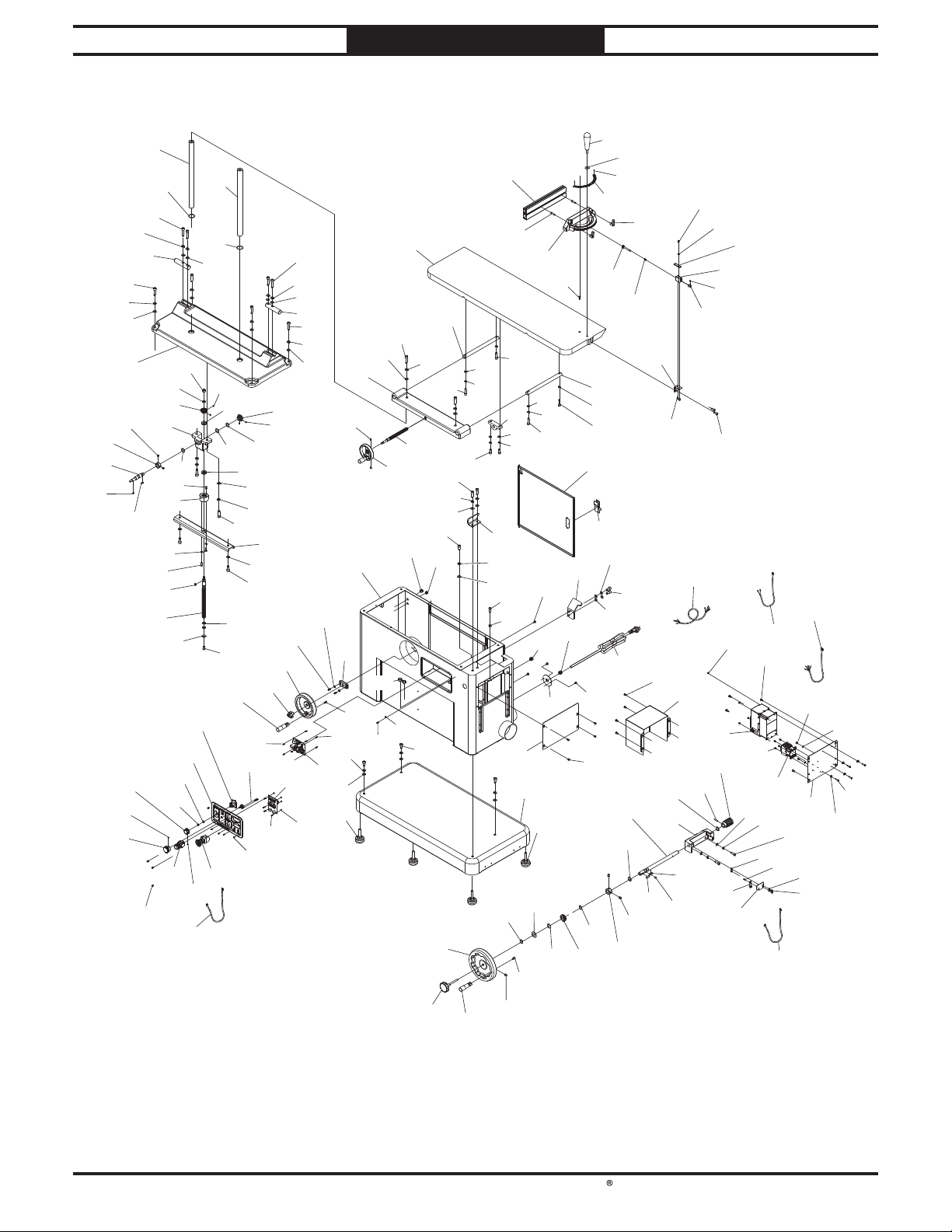
South Bend Tools
Model SB1127
343
Cabinet
PARTS
For Machines Mfd. Since 11/23
434
435
436
400
365
338
401
518
320
319
318
396
398
365
399
517
451
397
338
432
433
438
326
441
517
442
495
521
444
332
334
330
335
430
321
319
396
397
322
329
338
519
454
446
520
379
443
516
323
446
338
365
365
404
455
341
328
495
439
456
327
440
519
458
324
398
365
338
399
400
365
338
364
325
529
459
342
365
339
338
483
403
461
457
338
460
504
412
522
408
463
505
365
409
333
333
486
405
406
373
365
338
462
411
346
311
312
347
410
402
365
338
489
528
311
312
415
416
471
472
348
467
483
490
488
350
311
312
406
340
469
491
465
470
492
360
354
405
312
528
464
466
365
468
372
489
361
355
338
301
498
495
493
345
333
496
494
349
362
495
363
468
499
302
478
497
437
351
358
305
500
352
357
313
307
501
502
503
353
356
311
316
337
468
315
312
508
304
406
344
303
310
306
317
359
314
308
309
-48-
484
487
454
Page 51

South Bend Tools
For Machines Mfd. Since 11/23 Model SB1127
PARTS
Cabinet Parts List
REF PART # DE SCRIPTION REF PAR T # DE SCR IPT ION
301 PSB1127301 POWER CORD 12G 3W 138" 6-20P 355 PSB1127355 COMPRESSION SPRING 0.8 X 7.8 X 10.5
302 PSB1127302 MOTOR CORD 16G 4W 57" 356 PSB1127356 A DJ UST B LOCK
303 PSB1127303 P6 CORD 24G 6W 39" 357 PSB1127357 SET SCREW M4-.7 X 4
304 PSB1127304 P5 CORD 24G 4W 24" 358 PSB1127358 GEAR KNOB
305 PSB1127305 VFD DELTA VFD11AME21ANNAA 359 PSB1127359 PHLP HD SCR M5-.8 X 16
306 PSB1127306 ELECTRICAL MOUNTING BOARD 360 PSB1127360 ANGLE SCALE
307 PSB1127307 HEX N UT M5-.8 361 PSB1127361 RIVET 2 X 5MM NAMEPLATE, STEEL
308 PSB1127308 PHLP HD SCR M5-.8 X 20 PLASTIC 362 PSB1127362 INDICATOR MOUNTING BRA CKET
309 PSB1127309 FLAT WASHER 6.1 X 12.5 X 3.5MM 363 PSB1127363 CAP SCREW M5-.8 X 8
310 PSB1127310 B UTTON HD CAP SCR M4-.7 X 1 0 364 PSB1127364 FLAT WASHER 6MM
311 PSB1127311 FLAT WASHER 8MM 365 PSB1127365 LOCK WASHER 10MM
312 PSB1127312 LOCK WASHER 8MM 372 PS B 11 27372 B UTTON HD CAP SCR M6 -1 X 10
313 PSB1127313 CAP SCREW M8-1.25 X 16 373 PSB 1127373 CAP SCREW M10-1.5 X 25
314 PSB1127314 EXT TOOTH WASH ER 4M M 379 PSB11 2 7379 CAP SCREW M10-1.5 X 35
315 PSB1127315 CONTACTOR SDE MA-09 220-240V 396 PSB1127396 TABLE HEIGHT COLUMN
316 PSB1127316 BUTTON H D CA P S CR M4-.7 X 6 397 PSB1127397 OIL S EAL
317 PSB1127317 FLAT WASHER 5MM 398 PSB1127398 CAP SCREW M10-1.5 X 45
318 PSB1127318 BELT SPEED DIAL 399 PSB1127399 TILT S H AFT
319 PSB1127319 SET SCREW M4-.7 X 6 400 PSB1127400 CAP SCREW M10-1.5 X 40
320 PSB1127320 OSCILLATION DIAL 401 PSB1127401 BASE
321 PSB1127321 CONTROL P A N EL 402 PSB1127402 45 DEG STOP PLA TE
322 PSB1127322 CIRCUIT B OARD W/POTENTIOMETER EP-VR-CT 403 PSB1127403 TABLE CLEARA NCE BLOCK
323 PSB1127323 P OTEN TIOMETER COSMOS B 10K 404 PSB1127404 CAP SCREW M10-1.5 X 25
324 PSB1127324 DRO LCM CIRCUIT BOARD 405 PSB1127405 TABLE CLEA RANCE COLUMN
325 PSB1127325 HEX N UT M3-.5 PLA STIC 406 PSB1127406 CAP SCREW M8-1.25 X 35
326 PSB1127326 LOCK WASHER 6MM 40 8 PSB1127408 HANDWHEEL TYPE-17 100D X 10B -S
327 PSB1127327 STANDOFF-HEX MF M3-.5 X 6, M3-.5 PLASTIC 409 PSB1127409 TABLE CLEARANCE LEADSCREW
328 PSB1127328 BUTTON H D CAP S CR M 3-.5 X 8 410 PSB1127410 LEADSCREW BRACKET
329 PSB1127329 STOP BUTTON YIJIA LA36M-40(1A 1B) 411 PSB1127411 CAP SCREW M8-1.25 X 25
330 PS B 1 127330 S TART BUTTON YIAN KUANG YS -F1 412 PSB1127412 MAIN TABLE
332 PSB1127332 FLAT WASHER 8.1 X 13 X 0.5MM 415 PSB1127415 HEX BOLT M8-1.25 X 25
333 PSB11 27333 CAP SCREW M10-1.5 X 20 416 PSB1127416 HEX NUT M8 -1 .2 5
334 P SB1127334 HEX N UT M8-.75 430 PSB1127430 LOCK NUT M10-1.25
335 P SB112 7335 P4 CORD 24G 4W 12" 432 PSB1127432 B EVEL GEAR 26T
337 PSB11 27337 P2 CORD 24G 2W 12" 433 PSB1127433 LEADSCREW BRACKET
338 PS B 1 127338 FLAT WASHER 10MM 434 PSB1127434 LOCK COLLAR
339 PSB 1 1 27339 CONTROL DRIVER CIRCUIT B OARD 435 PSB1127435 HANDWHEEL SHAFT
340 PSB1127340 RUBBER BUMPER 436 PSB1127436 KEY 4 X 4 X 12
341 PSB1127341 PHLP HD SCR M3-.5 X 6 437 PSB1127437 KEY 4 X 4 X 8
342 PSB1127342 STANDOFF-HEX MF M3-.5 X 6, M3-.5 438 PSB1127438 LEADSCREW NUT
343 PSB1127343 FIXED HAN DLE 38 X 115, M8-1.25 X 45 439 PSB1127439 HEIGHT LIMIT PLATE
344 PSB1127344 PHLP HD SCR M3-.5 X 6 440 PSB 1127440 BEVEL GEA R 26T
345 PSB1127345 FENDER WASHER 8MM 441 PSB 1127441 CAP SCREW M6-1 X 16
346 PSB1127346 FENCE 442 PSB 1127442 TABLE HEIGHT LEADSCREW
347 PSB1127347 HEX BOLT 1/4-20 X 1 443 PSB1127443 FLAT WASHER 10MM
348 PSB1127348 MITER GAUGE 444 PSB1 127444 FENDER WASHER 8MM
349 PSB1127349 ADJUSTABLE HANDLE 1/4-20, 2L 446 PS B1127446 THRUS T B EARIN G 5110 2
350 PSB1127350 HIN GE PIN 451 PSB1127451 BUTTON H D CA P S CR M5-.8 X 8
351 PSB1127351 PHLP HD SCR M5-.8 X 8 454 PSB1127454 F OLDIN G H AN DLE 23 X 85. 5, M6 -1
352 PSB1127352 FLAT WASHER 5MM 455 PSB1127455 KNOB B OLT M8 -1.25 X 1 8 , 3-LOB E, D42
353 PSB1127353 INDICATOR 456 PSB1127456 HANDWHEEL TYPE-18 150D X 12.7B-K
354 PSB1127354 INDEX PIN 457 PSB1127457 FLAT HD CAP SCR M6-1 X 16
-49-
Page 52

South Bend Tools
Model SB1127
PARTS
For Machines Mfd. Since 11/23
Cabinet Parts List (Cont.)
REF PART # D E SCR IPT ION REF PART # DE SCRIPTION
458 PSB1127458 BUTTON H D CAP S CR M6-1 X 10 492 PSB1127492 MAGNETIC SEN SOR RING
459 PSB1127459 HANDWHEEL BRACKET 493 PSB1127493 LOCK COLLAR
460 PSB1127460 STRA IN RELIEF TYPE-5 25.4MM 494 PSB1127494 S ET S CREW M8-1.25 X 10
461 PSB1127461 CAB INET 495 PSB1127495 FLAT WASHER 19.1 X 25.4 X 1.6MM
462 PSB1127462 S TRAIN RELIEF TYPE-1 1/2" 496 PSB1127496 KEY 5 X 5 X 18
463 PSB1127463 S TRAIN RELIEF TYPE-1 1/2" 497 PSB1127497 WOODRUFF KEY 5 X 22MM
464 PSB1127464 CA BIN ET DOOR 498 PSB1127498 TILT SH AFT
465 PSB1127465 90 DEG STOP PLATE 499 PSB1127499 PLATEN TILT B RACKET
466 PSB1127466 DOOR LA TCH 500 PSB1127500 ROLL PIN 5 X 30
467 PSB1127467 STRA IN RELIEF TYPE-1 11 /1 6" 501 PSB1127501 WORM GEA R
468 PSB1127468 PHLP HD SCR M6-1 X 10 502 PSB1127502 TILT S EN SOR CIRCUIT B OARD
469 PSB1127469 CORD PLATE 503 PSB1127503 SENS OR MOUNTING B RACKET
470 PSB 1 1 27470 STRAIN RELIEF TYPE-1 11 /16" 504 PSB1127504 BUTTON HD CA P SCR M4-.7 X 8
471 PS B 1 1 27471 SIDE PAN EL 505 PSB1127505 EXT TOOTH WA SHER 4MM
472 PSB 11 27472 CABINET BASE 508 PSB1127508 H EX NUT M6-1
478 P S B 1 127478 ELECTRICAL BOX 516 PSB1127516 HEX BOLT M8-1.25 X 16
483 PSB1127483 ADJUSTABLE FOOT M12-1.75 X 53 517 PSB1127517 KEY 5 X 5 X 16
484 PSB1127484 KN OB B OLT M1 0-1.5 X 1 9, 8-LOB E, D60 518 PSB1127518 SET SCREW 5/16-18 X 5/16
486 PSB1127486 H ANDWHEEL TYPE-31 200D X 19.1B -K 519 PSB1127519 SET SCREW M5-.8 X 5
487 PSB1127487 SET SCREW M6-1 X 12 520 PSB1127520 WA VY WASHER 20 .9MM
488 PSB1127488 BUTTON H D CAP S CR M6-1 X 12 521 PSB1127521 CAP SCREW M6-1 X 8
489 PSB1127489 EXT RETAIN IN G RIN G 20 MM 522 PSB1127522 CAP SCREW M10-1.5 X 30
490 PSB1127490 FLAT WASHER 21 X 37 X 1MM 528 PSB1127528 CAP SCREW M8-1.25 X 30
491 PSB1127491 WAVY WAS HER 26.8MM 529 PSB1127529 SET SCREW M6-1 X 6
-50-
Page 53
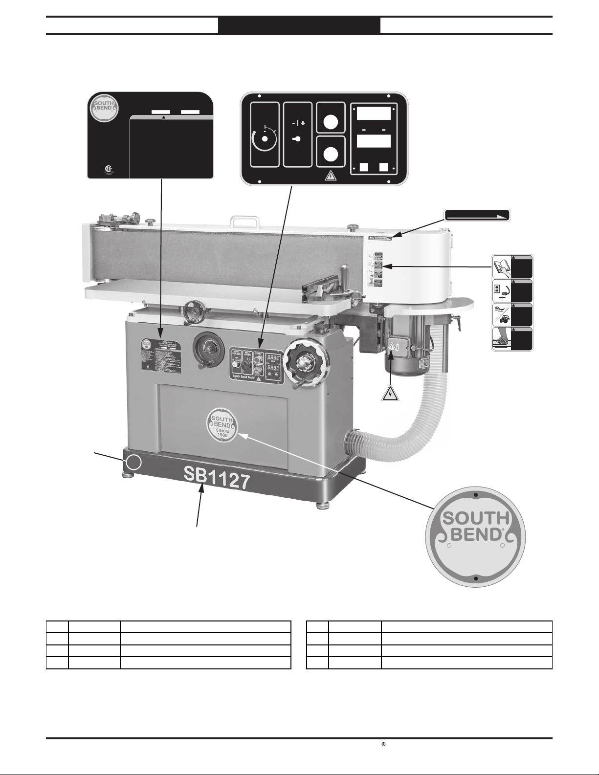
South Bend Tools
For Machines Mfd. Since 11/23 Model SB1127
601
602
PARTS
Machine Labels
MODEL SB1127
9" x 138-1/2" VARIABLE-SPEED
SINCE
1906
Power Req.: 230V, 1-Ph, 60 Hz, 20A
Main Motor: 3 HP, 230V, 3-Ph, 60 Hz, 8.5A
Full-Load Current Rating: 18A
Sanding Belt Size: 9" x 138-1/2"
Sanding Belt Speed: 1050–4250 FPM
Oscillation Stroke: 1/4"–3/8"
Oscillation Rate: 30–50 OPM
Main Table Travel: 7-3/8"
Main Table Height: 33-1/4"–40-5/8"
End Table Travel: 7"
Sanding Belt Tilt: 0–45°
Weight: 661 lbs.
Made in Taiwan to South Bend Specifications
OSCILLATING EDGE SANDER
Serial No: MFG Date:
!
To reduce the risk of serious injury when using this machine:
1. Read and understand owner’s manual before operating.
2. Always wear approved eye protection and respirator.
3. Only plug power cord into a grounded outlet.
4. Support workpiece with miter gauge, backstop, or worktable.
5. Maintain 1/16" maximum clearance between table and sandpaper.
6. Never touch moving sandpaper.
7. Always sand in accordance with directional arrows on machine.
8. Make sure sander is properly assembled, adjusted, and stable before operating.
Only operate with all guards in place.
9. Never sand pointed stock with point facing into sanding rotation, and never force
workpiece into sanding surface.
10. Only remove jammed pieces when sandpaper is stopped.
11. Turn motor OFF and disconnect power before changing sandpaper, removing
jammed pieces, making adjustments, or servicing.
12. Do not wear loose clothing, gloves, jewelry, or other articles that can get entangled.
Tie back long hair and roll up sleeves.
13. Never reach over moving sanding belt.
14. Do not expose to rain or use in damp locations.
15. Do not operate under influence of drugs or alcohol, or when tired.
16. Prevent unauthorized use by children or untrained users; restrict access or disable
machine when unattended.
WARNING!
OSC.
PER MIN.
OFF
50
South Bend Tools
30
BELT
SPEED
START
®
STOP
ALARM
SET
FPM
READY
45°
0°
SET
603
BELT ROTATION
604
!
WARNING!
INJURY HAZARD
Do not use machine
if you have not read
the manual. Visit
southbendtools.com
or call 360-734-1540
to get a manual.
!
WARNING!
INJURY/SHOCK
HAZARD
!
To avoid shock or
accidental starting,
disconnect power
before adjusting or
servicing machine.
!
WARNING!
EYE/LUNG INJURY
HAZARD
Always wear ANSIapproved safety
glasses and
respirator when
using this
equipment.
!
WARNING!
ABRASION INJURY
HAZARD
DO NOT touch
moving sanding belt
or personal injury
may occur!
605
608
606
SB1127
607
SINCE
1906
REF PART # D E SCR IPT ION REF PART # DE SCR IPT ION
601 PSB1127601 MACHINE ID LABEL 605 PSB1127605 ELECTRICITY LABEL
602 PSB1127602 CON TROL PA NEL LABEL 606 PSB1127606 SOUTH BEND NAMEPLATE 152MM
603 PSB1127603 BELT ROTATION LA B EL 607 PSB1127607 MODEL NUMBER LAB EL
604 PSB1127604 COMB O WA RN ING LABEL 608 PSB1127608 TOUCH-UP PAINT, S B DARK BLUE
-51-
Page 54
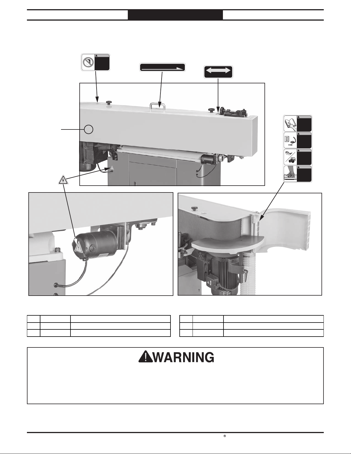
South Bend Tools
Model SB1127
609
PARTS
Machine Labels (Cont.)
!
WARNING!
INJURY HAZARD
611
605
Keep door closed
while machine is
operating.
Disconnect power
before opening
door.
603
BELT ROTATION
610
DOWN
BELT TRACKING
For Machines Mfd. Since 11/23
UP
604
!
WARNING!
INJURY HAZARD
Do not use machine
if you have not read
the manual. Visit
southbendtools.com
or call 360-734-1540
to get a manual.
!
WARNING!
INJURY/SHOCK
HAZARD
!
To avoid shock or
accidental starting,
disconnect power
before adjusting or
servicing machine.
!
WARNING!
EYE/LUNG INJURY
HAZARD
Always wear ANSIapproved safety
glasses and
respirator when
using this
equipment.
!
WARNING!
ABRASION INJURY
HAZARD
DO NOT touch
moving sanding belt
or personal injury
may occur!
REF PART # D E SCR IPT ION REF PART # DE SCR IPT ION
603 PSB1127603 BELT ROTATION LA B EL 609 PSB1127609 KEEP DOOR CLOSED LABEL
604 PSB1127604 COMB O WA RN ING LABEL 610 PSB1127610 B ELT TRA CKIN G LAB EL
605 PSB1127605 ELECTRICITY LABEL 611 PSB1127611 TOUCH-UP PAINT, SB GRAY
The safety labels provided with your machine are used to make the operator aware of the
machine hazards and ways to prevent injury. The owner of this machine MUST maintain the
original location and readability of these safety labels. If any label is removed or becomes
unreadable, REPLACE that label before using the machine again. Contact South Bend Tools at
(360) 734-1540 or www.southbendtools.com to order new labels.
-52-
Page 55

Warranty
This quality product is warranted by South Bend Tools to the original buyer for 2 years from the date
of purchase. This warranty does not apply to consumable parts, or defects due to any kind of misuse,
abuse, negligence, accidents, repairs, alterations or lack of maintenance. We do not reimburse for
third party repairs. In no event shall we be liable for death, injuries to persons or property, or for
incidental, contingent, special or consequential damages arising from the use of our products.
We do not warrant or represent that this machine complies with the provisions of any law, act,
code, regulation, or standard of any domestic or foreign government, industry, or authority. In
no event shall South Bend’s liability under this warranty exceed the original purchase price paid
for this machine. Any legal actions brought against South Bend Tools shall be tried in the State of
Washington, County of Whatcom.
This is the sole written warranty for this machine. Any and all warranties that may be implied by law,
including any merchantability or fitness, for any purpose, are hereby limited to the duration of this
warranty.
Thank you for your business and continued support.
For further information about this warranty, visit
, or scan
the QR code below to be automatically directed to our warranty page.
https://www.grizzly.com/forms/warranty
WARRANT Y
southbendtools.com
Page 56

southbendtools.com
Printed In Taiwan #CS22944
 Loading...