

Page 1

READ THIS FIRST
MODEL SB1118
***IMPORTANT UPDATE***
SINCE
1906
Applies to Models Mfd. Since 10/21
and Owner’s Manual Printed 12/21
The following changes were recently made since the owner’s manual was printed:
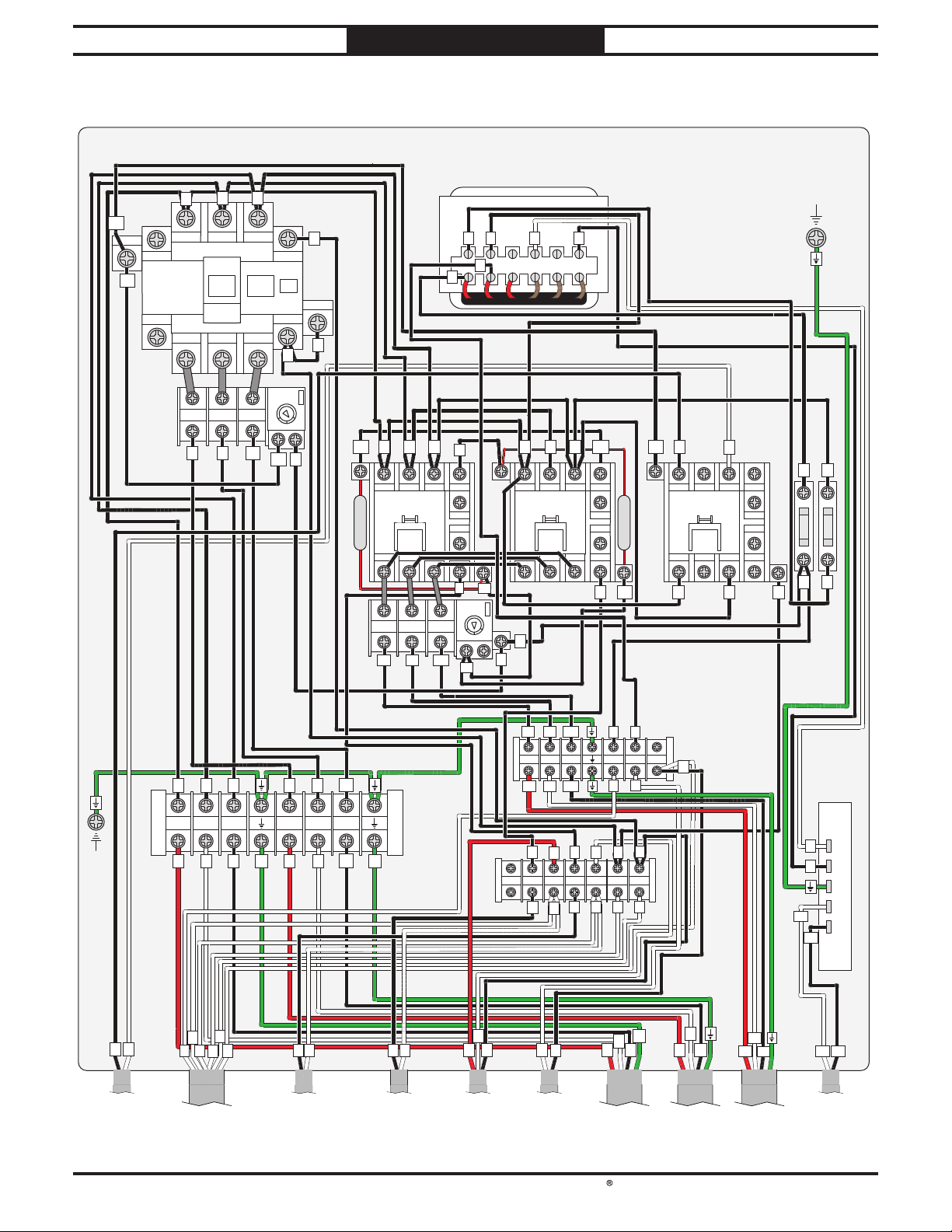
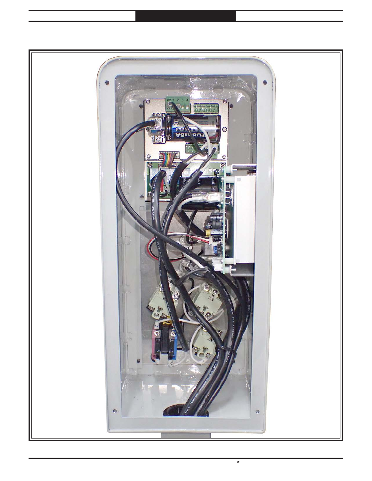
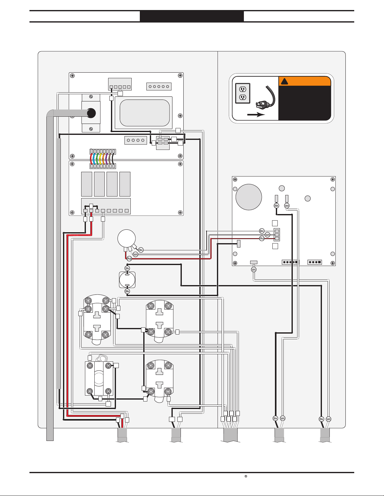
• Wiring diagrams and electrical photos have changed.
Aside from this information, all other content in the owner’s manual applies and MUST be read and
understood for your own safety. IMPORTANT: Keep this update with the owner’s manual for future
reference.
If you have any further questions about this manual update or the changes made to the machine,
contact our Technical Support at (360) 734-1540 or email www.southbendtools.com.
SINCE
1906
Copyright © May, 2023 by South Bend Tools
WARNING: No portion of this manual may be reproduced without written approval.
#JP22720 Printed in Taiwan
Page 2
South Bend Tools
Model SB1118
Panel)
Motor)
ELECTRICAL
(Replaces Page 62 in Owner's Manual)
Electrical Box Wiring Diagram
Electrical Box
Mfd. Since 10/21
16
16
A1
16
1/L1 5/L33/L2
7
Contactor
SDE
MA-55
8
2/T1
OL
Relay
SDE
RA-30
S
R
4/T2
1/2 3/4 5/6
UWV
6/T3
0
95
L1/1 L3/5 21NCL2/3
T1/2
0
GDM 40VA
L N
R
S
Contactor
SDE MA-09
R
T2/4
GND
T
10
13
14
22NC
T3/6
8
17
16
R
L1/1 L3/5 21NCL2/3
Contactor
SDE MA-09
T2/4
T1/2
R
T
0
T
13
2A 250V
14
T3/6
22NC
Fuses
0
T
4
T
Transformer
T
3
13
B2
14
4
4
AMP
RESET
34
48
40
95
96
16
R S
0
10
Wave Filter
Cetus 0.1uF 120 Ohm
SDE RA-20
OL Relay
L1/1 L3/5 21NCL2/3
T1/2
1/2 3/4 5/6
U1 V1 W1
Contactor
SDE MA-09
T2/4
T
T3/6
220V 440V0V 0V 24V 220V
R
T
1
0
9
13
14
22NC
6
17
AMP
RESET
1.6
2.5
2
98
96
17
GND
R
T
( To
Transformer)
Pg. 66
R S T
R S T U V W
R S T
3
7
0
5
2
4
UWV
U V
G
6
5
(To Upper
(To Control
This Update
Limit Switch)
Pg. 66
Pg. 4
G
W
8
(To Lower
Limit Switch)
Pg. 66
U1 V1
W1
V1 W1 0 1 2U1
U1 V1 W1
7
1
0
Power
2
1
0
3
586
4
Supply
Mean Well
RS-15-24
L
N
5 4
8 7
6
6
8
7
5
7
7
3
(To LED,
3-Wire)
1
2
(To Safety
Switch)
Pg. 64 Pg. 66
3
3
5
4
G
RST
(To Power
Supply)
V
U
W
(To Main
Motor)
V1
U1
W1
(To Table
V-
V+
V-
(To LED,
2-Wire)
Pg. 64
V+
Pg. 61 Pg. 65 Pg. 65
-2-
Page 3
South Bend Tools
Mfd. Since 10/21 Mo del SB1118
(Replaces Page 63 in Owner's Manual)
ELECTRICAL
Control Box
-3-
Page 4
South Bend Tools
Model SB1118
Sensor
(7-Post Terminal Bar)
(7-Post Terminal Bar)
ELECTRICAL
(Replaces Page 64 in Owner's Manual)
Control Box Wiring Diagram
Control Panel
Digital Readout
M15S-DC24V
Mfd. Since 10/21
0V 1 2 3 4
13
0
C1 N0 C2 N0 C3 N0 C4 N0
3
735
D Battery
0
Circuit Board
Potentiometer
PWM 10 KOHM
!
WARNING!
!
V-
V+
14
24
0V
Low
T1
AC1
AC2
High
T2
SHOCK HAZARD!
Disconnect power
before working on
wiring.
M+ M-
T3 T4
VR2
P2
VR1
P1
Circuit Board
PWM AC 120V
P3
To Magnetic
Pg. 67
MAIN MOTOR
Button
YK YS-PF1-3
X1
4
13
10A 250VAC
21
2
12
NCNC
Circuit Breaker
Zing Ear ZE-800
X2
0
3
14
3
22
14
NO
4
EMERGENCY
STOP Button
YIJIA LA36M
NO
3
3
13
7
3
5
To Electrical Box
This Update
Pg. 2
22
14
3
22
14
3
3
10A 250VAC
10A 250VAC
21
TABLE UP
13
21
TAB LE
DOWN
Button
YS-F1-3
13
7
V+
5
To Power Supply
Pg. 2
Button
YS-F1-3
V-
540
7
3
2
To Electrical Box
This Update
Pg. 2
To Feed Motor
To Transformer
Pg. 66Pg. 60This Update
-4-
Page 5

southbendtools.com
Page 6
READ THIS FIRST
90
REF PART # DE SCR IPTION
MODEL SB1118
***IMPORTANT UPDATE***
SINCE
1906
Applies to Models Mfd. Since 03/23
and Owner’s Manual Printed 12/21
The following change was recently made since the owner’s manual was printed:
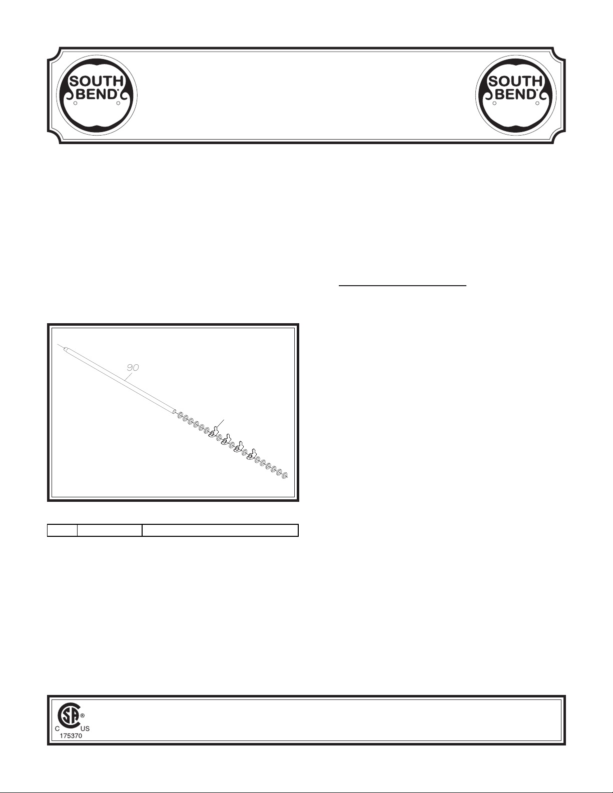
• Anti-kickback pawl has changed.
Aside from this information, all other content in the owner’s manual applies and MUST be read and
understood for your own safety. IMPORTANT: Keep this update with the owner’s manual for
future reference.
If you have any further questions about this manual update or the changes made to the machine,
contact our Technical Support at (360) 734-1540 or email www.southbendtools.com.
Revised Parts
SINCE
1906
93V2
93V2 PSB1118093V2 ANTI-KICKBACK PAWL V2.03.23
WARNING: No portion of this manual may be reproduced without written approval.
Copyright © April, 2023 by South Bend Tools
#JM22689 Printed in Taiwan
Page 7
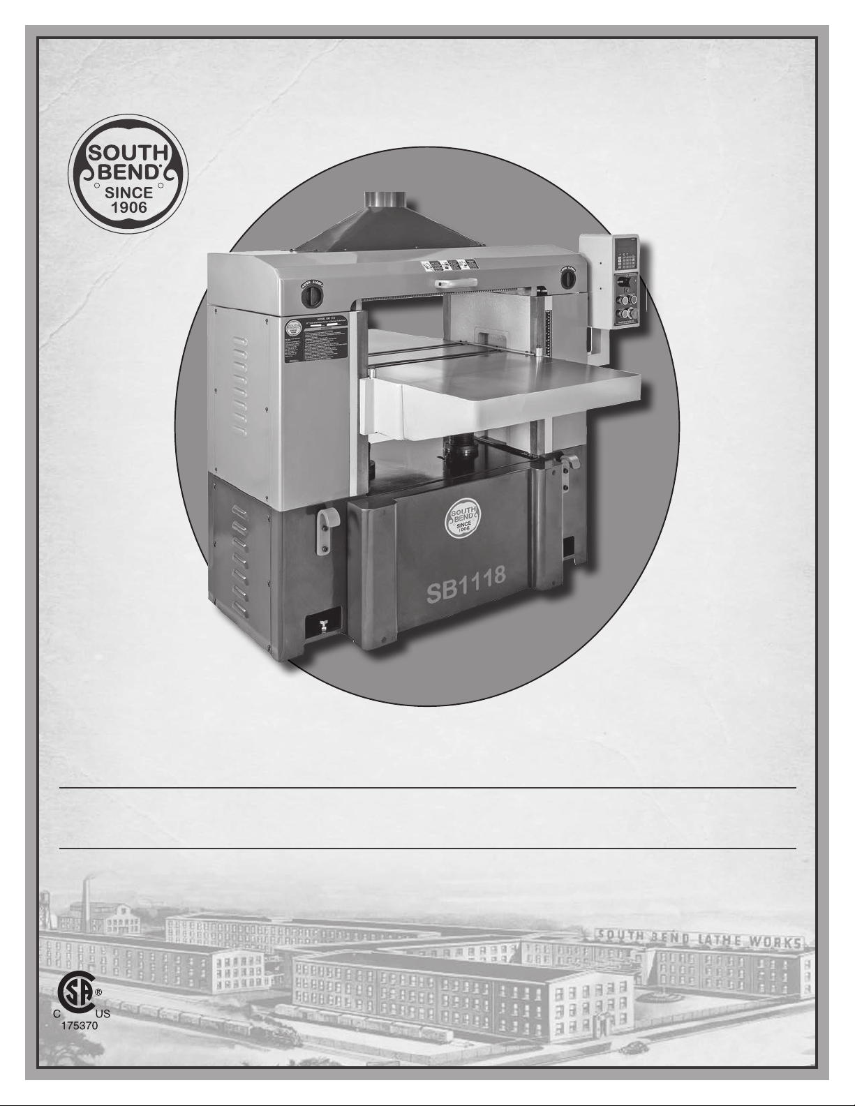
25" EXTREME-SERIES PLANER
MODEL SB1118
***Keep for Future Reference***
OWNER'S MANUAL
South Bend Tools
A Tradition of Excellence
For Machines Mfd. Since 10/21 (V1.12.21)© December, 2021 by South Bend Tools
®
Page 8

We stand behind our machines. If you have any service questions, parts requests or general questions
about your purchase, feel free to contact us.
South Bend Tools
P.O. Box 2027
Bellingham, WA 98227
Phone: (360) 734-1540
Fax: (360) 676-1075 (International)
Fax: (360) 734-1639 (USA Only)
Email: [email protected]
For your convenience, any updates to this manual will be available to download free of charge
www.southbendtools.com
Scope of Manual
This manual helps the reader understand the machine, how to prepare it for operation, how to control
it during operation, and how to keep it in good working condition. We assume the reader has a basic
understanding of how to operate this type of machine, but that the reader is not familiar with the
controls and adjustments of this specific model. As with all machinery of this nature, learning the
nuances of operation is a process that happens through training and experience. If you are not an
experienced operator of this type of machinery, read through this entire manual, then learn more
from an experienced operator, schooling, or research before attempting operations. Following this
advice will help you avoid serious personal injury and get the best results from your work.
We've made every effort to be accurate when documenting this machine. However, errors sometimes
happen or the machine design changes after the documentation process—so
exactly match your machine.
contact our
We highly value customer feedback on our manuals. If you have a moment, please share your
experience using this manual. What did you like about it? Is there anything you would change to
make it better? Did it meet your expectations for clarity, professionalism, and ease-of-use?
South Bend Tools
C
P.O. Box 2027
Bellingham, WA 98227
Email: [email protected]
Manual Feedback
If a difference between the manual and machine leaves you in doubt,
customer service for clarification.
the manual may not
/O Technical Documentation Manager
Updates
through our website at:
Customer Service
Page 9

Table of Contents
INTRODUCTION ............................................................... 2
Identification
Description of Controls & Components
Internal Components
Product Specifications
SAFETY
Understanding Risks of Machinery
Basic Machine Safety
Additional Planer Safety
PREPARATION
Preparation Overview
Required for Setup
Power Supply Requirements
Converting Voltage to 440V
Unpacking
Inventory
Cleaning & Protecting
Location
Lifting & Moving
Leveling
Anchoring to Floor
Assembly
Dust Collection
Checking Gearbox Oil Levels
Power Connection
Test Run
Inspections & Adjustments
OPERATION
Operation Overview
Stock Inspection & Requirements.....................28
Wood Types
Planing Tips
Common Cutting Problems
Depth of Cut
Using Table Height Handwheel
Using TABLE UP/DOWN Buttons
Using Digital Readout
Setting Feed Rate
Bed Roller Height
Rotating/Replacing Cutterhead Inserts
ACCESSORIES
........................................................ 2
..............3
........................................... 5
........................................6
................................................................................ 8
.................... 8
..........................................8
................................... 10
.............................................................. 11
........................................11
............................................. 11
............................. 12
..............................14
..........................................................16
............................................................ 16
.......................................17
.............................................................. 18
................................................19
.............................................................. 19
.............................................20
............................................................20
...................................................21
............................ 22
..............................................23
............................................................. 24
...............................26
.................................................................... 27
........................................... 27
........................................................28
....................................................... 29
............................... 29
....................................................... 31
........................ 31
...................32
....................................... 32
..............................................34
..............................................35
............36
.............................................................. 37
MAINTENANCE
Maintenance Schedule
Cleaning
Unpainted Cast Iron
Lubrication
Replacing Digital Readout Battery
Anti-Kickback Fingers
Tensioning/Replacing Belts
SERVICE........................................................................... 44
Setting Feed Rollers, Chip Breaker & Pressure
Bar Heights
Adjusting Feed Roller Spring Tension
Calibrating Table Height Indicator
Replacing Feed Motor Brushes
Checking Pulley Alignment
Adjusting Table Parallelism
Tensioning Table Height Chain
Adjusting Table Gibs
Calibrating Bed Rollers
Calibrating Digital Readout
TROUBLESHOOTING
ELECTRICAL
Electrical Safety Instructions
Electrical Overview
Electrical Box
Electrical Box Wiring Diagram
Control Box.........................................................63
Control Box Wiring Diagram
Main Motor Wiring Diagrams
Table Motor Wiring Diagrams
Electrical Component Wiring Diagrams
Electrical Component Photos
PARTS................................................................................68
Base & Motors
Column
Headstock
Table
Gearbox
Electrical Components
Machine Labels
WARRANTY
.............................................................38
...............................................................71
................................................................... 75
..............................................................77
.............................................................38
.......................................38
.......................................... 38
......................................................... 39
................... 42
.......................................43
............................... 44
........................................................ 46
..............49
..................50
......................... 50
...............................51
..............................52
........................ 53
.........................................54
..................................... 54
.............................. 55
................................................. 56
................................................................... 59
...........................59
............................................60
..................................................... 61
......................... 62
............................64
........................... 65
..........................65
..........66
............................ 67
...................................................68
........................................................... 73
.......................................78
.................................................. 80
..................................................................... 81
Page 10
South Bend Tools
Model SB1118
INTRODUCTION
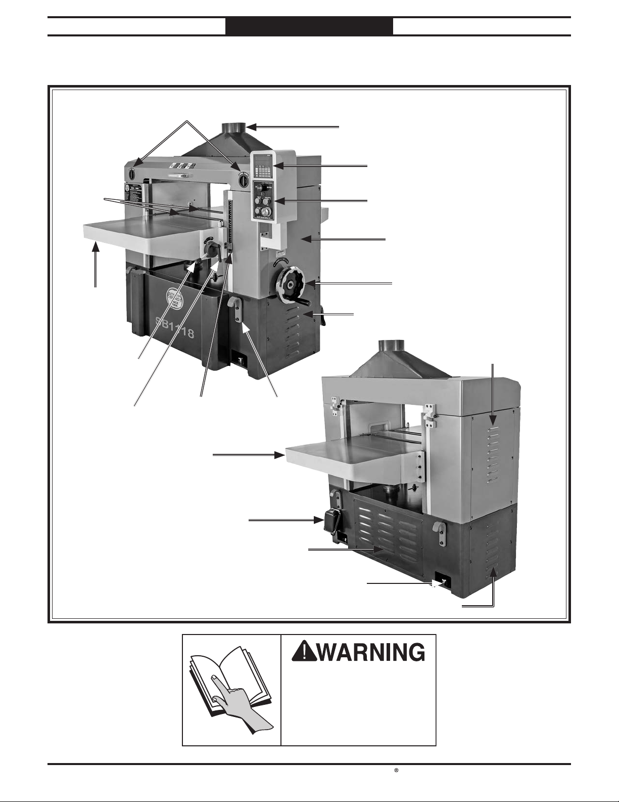
Identification
INTRODUCTION
For Machines Mfd. Since 10/21
-2-
Incorrect use of this
machine can result in
death or serious injury.
For your own safety, read
and understand this entire
document before using.
Page 11
South Bend Tools
For Machines Mfd. Since 10/21 Model SB1118
Description of Controls & Components
INTRODUCTION
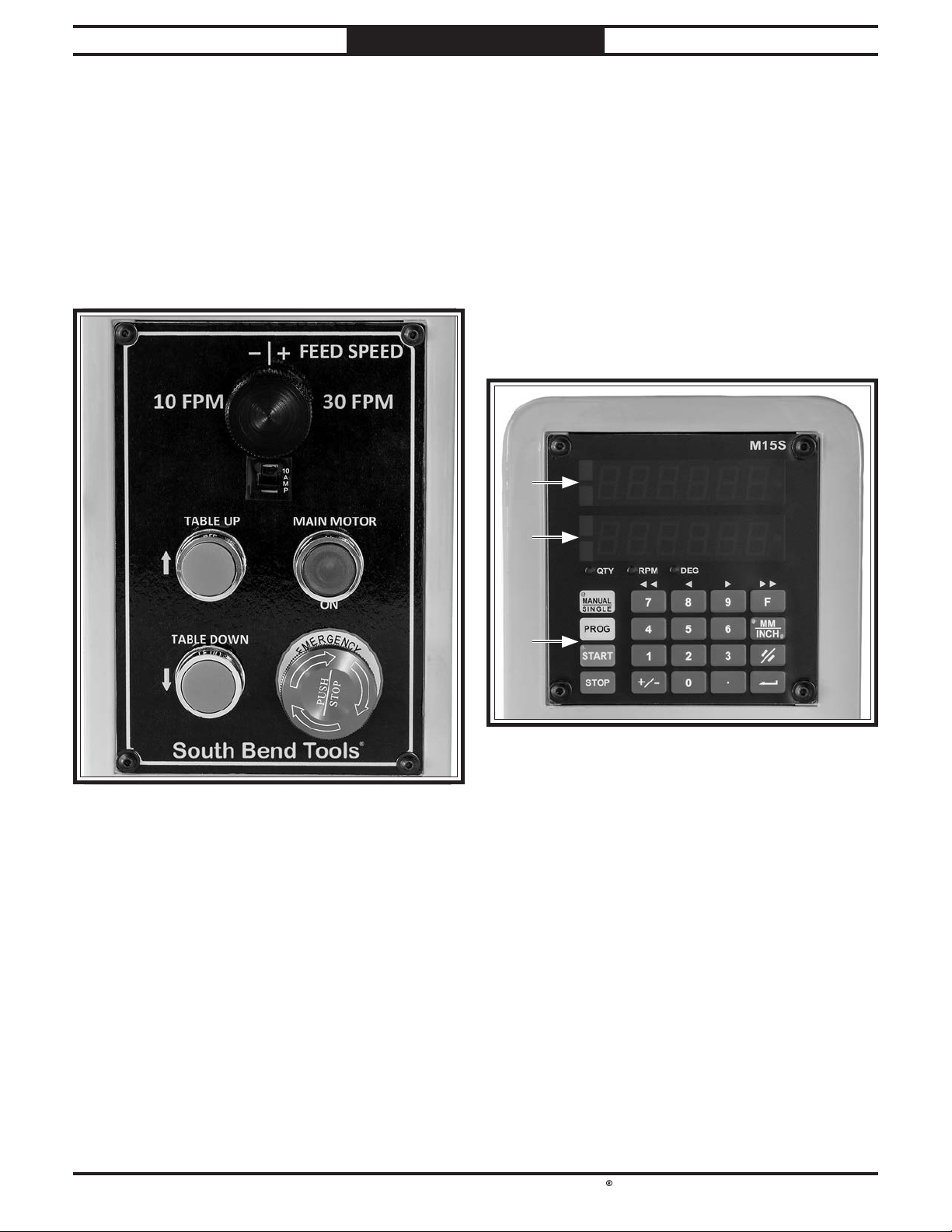
D. TABLE DOWN Button: Lowers table when
pressed. When used in conjunction with
digital readout, will lower table to a pre-set
elevation.
Refer to Figures 1–3 and the following
descriptions to become familiar with the basic
controls and components used to operate this
machine.
Control Panel
E. MAIN MOTOR/ON Button: Turns cutterhead
and feed motors ON. Illuminates when
machine is connected to power.
F. EMERGENCY STOP Button: Stops all
machine functions when pressed. Twist
clockwise to reset.
Digital Readout
A. FEED SPEED Control Knob: Controls speed
at which workpiece moves past cutterhead.
Turn clockwise to increase speed; turn
counterclockwise to decrease speed.
B. Circuit Breaker: Stops motor function if
motor overheats. Allow motor to cool, then
move switch up to reset.
C. TABLE UP Button: Raises table when
pressed. When used in conjunction with
digital readout, will raise table to a pre-set
elevation.
G. Target Window: Shows target table position
value entered on keypad.
H. Actual Window: Shows current actual table
position value.
I. Keypad: Used to enter table elevation and
digital commands.
-3-
Page 12
South Bend Tools
Model SB1118
INTRODUCTION
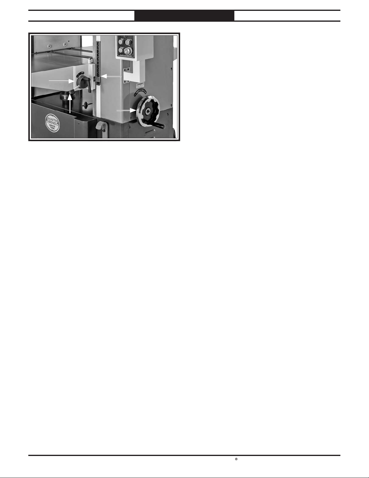
J. Bed Roller Height Handle: Adjusts height of
bed rollers from 0.002"–0.050".
K. Table Height Scale: Shows elevation of table
beneath cutterhead. The measurement
indicated along top edge of red indicator
shows effective thickness of workpiece after
planing.
L. Table Height Handwheel: Raises and lowers
table. One full revolution moves table
approximately
M. Bed Roller Height Lock Lever: Secures bed
rollers in position.
For Machines Mfd. Since 10/21
1
⁄32".
-4-
Page 13
South Bend Tools
For Machines Mfd. Since 10/21 Model SB1118
INTRODUCTION
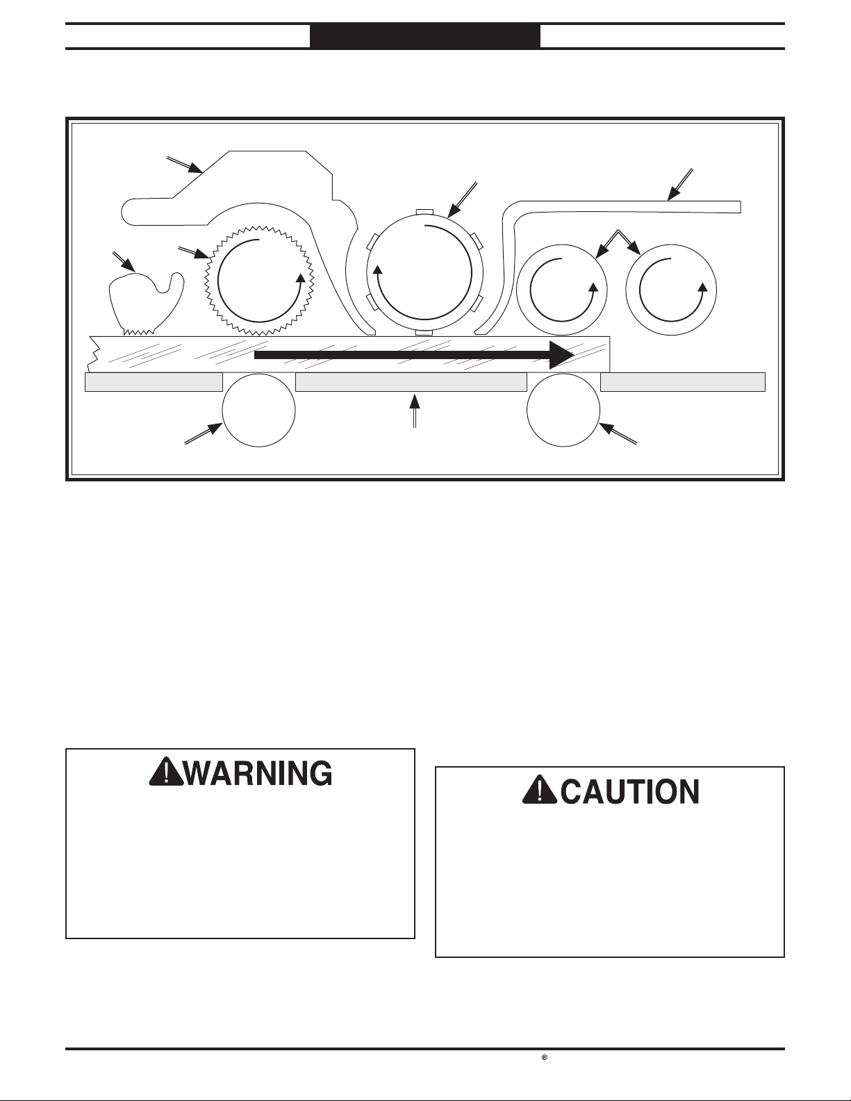
Internal Components
A. Anti-Kickback Fingers: Provide additional
safety for operator.
B. Serrated Infeed Roller: Pulls workpiece
toward cutterhead.
C. Chip Breaker: Breaks off chips created by
cutterhead to prevent tearout and diverts
chips to dust hood.
D. Helical Cutterhead: Holds indexable carbide
inserts that remove material from workpiece.
Like all machinery, there is potential danger
when operating this machine. Accidents are
frequently caused by lack of familiarity or
failure to pay attention. Use this machine with
respect and caution to decrease the risk of
operator injury. If normal safety precautions
are overlooked or ignored, serious personal
injury may occur.
E. Pressure Bar: Stabilizes workpiece as it
leaves cutterhead and assists in deflecting
wood particles toward dust hood.
F. Outfeed Rollers: Pull workpiece through the
planer.
G. Bed Rollers: Provide upward pressure on
workpiece, enabling feed rollers to pull the
workpiece along.
H. Planer Table: Provides a smooth and level
path for workpiece as it moves through planer.
No list of safety guidelines can be complete.
Every shop environment is different. Always
consider safety first, as it applies to your
individual working conditions. Use this and
other machinery with caution and respect.
Failure to do so could result in serious
personal injury, damage to equipment, or poor
work results.
-5-
Page 14

South Bend Tools
Model SB1118
INTRODUCTION
Product Specifications
Model SB1118
Model SB1118
For Machines Mfd. Since 10/21
25" Planer with Helical Cutterhead
Product Dimensions
Weight...........................................................................................................................................................
Width (side-to-side) x Depth (front-to-back) x Height......................................................... 54-1/2 x 57 x 54-1/2 in.
Footprint (Length x Width)........................................................................................................... 47-1/2 x 24-1/2 in.
Shipping Dimensions
Type.......................................................................................................................................................... Wood Crate
Content..........................................................................................................................................................
Weight...........................................................................................................................................................
Length x Width x Height................................................................................................................... 59 x 38 x 63 in.
Must Ship Upright................................................................................................................................................ Yes
Electrical
Power Requirement................................................................................................... 220V or 440V, 3-Phase, 60 Hz
Prewired Voltage................................................................................................................................................
Full-Load Current Rating...............................................................................................
Minimum Circuit Size..................................................................................................... 50A at 220V, 30A at 440V
Connection Type.................................................................................................. Permanent (Hardwire to Shutoff)
Switch Type....................................................................................... Control Panel w/Magnetic Switch Protection
Motors
Main
Horsepower.............................................................................................................................................
Phase.................................................................................................................................................... 3-Phase
Amps................................................................................................................................................. 37A/18.5A
Speed................................................................................................................................................ 3420 RPM
Type........................................................................................................................................
Power Transfer ..........................................................................................................................................
Bearings................................................................................................ Shielded & Permanently Lubricated
Extreme-Series Planer
45A at 220V, 26.5 at 440V
TEFC Induction
1870 lbs.
Machine
2057 lbs.
220V
15 HP
Belt
Table Elevation
Horsepower............................................................................................................................................ 1/2 HP
Phase.................................................................................................................................................... 3-Phase
Amps........................................................................................................................................................
Speed................................................................................................................................................
Type........................................................................................................................................ TEFC Induction
Power Transfer ....................................................................................................................................... Chain
Bearings.................................................................................................... Sealed & Permanently Lubricated
-6-
2A/1A
1720 RPM
Page 15

South Bend Tools
For Machines Mfd. Since 10/21 Model SB1118
Feed
Dust Port Size............................................................................................................................................ 6 in.
INTRODUCTION
Horsepower............................................................................................................................................
Phase............................................................................................................................................
Amps............................................................................................................................................................. 8A
Speed................................................................................................................................................ 2500 RPM
Type................................................................................................................................................... DC Motor
Power Transfer ..........................................................................................................................................
Bearings....................................................................................................
Main Specifications
Main Specifications
Planer Size............................................................................................................................................... 25 in.
Max. Cut Width....................................................................................................................................... 25 in.
Min. Stock Length................................................................................................................................... 10 in.
Min. Stock Thickness..............................................................................................................................
Max. Stock Thickness................................................................................................................................
Number of Cuts Per Inch..................................................................................................................... 245 - 82
Number of Cuts Per Minute.................................................................................................................. 29,400
Cutterhead Speed............................................................................................................................ 4900 RPM
Planing Feed Rate........................................................................................................................
Max. Cut Depth Planing Full Width.....................................................................................................
Max. Cut Depth Planing 6-Inch Wide Board........................................................................................ 1/4 in.
Cutterhead Info
Cutterhead Type.................................................................................................................................... Helical
Cutterhead Diameter ......................................................................................................................... 3-1/2 in.
Number of Cutter Rows..................................................................................................................................
Number of Indexable Cutters.....................................................................................................................
Cutter Insert Type................................................................................................. 30 deg. Indexable Carbide
Cutter Insert Size Length...................................................................................................................... 15mm
Cutter Insert Size Width........................................................................................................................ 15mm
Cutter Insert Size Thickness................................................................................................................
3/4 HP
Single-Phase
Belt
Sealed & Permanently Lubricated
1/4 in.
9 in.
10 - 30 FPM
1/8 in.
6
174
2.5mm
Table Info
Table/Headstock Movement......................................................................................................................
Table Bed Size Length............................................................................................................................. 57 in.
Table Bed Size Width.............................................................................................................................. 25 in.
Table Bed Size Thickness.......................................................................................................................... 2 in.
Number of Bed Rollers....................................................................................................................................
Floor-to-Table Height.......................................................................................................................
Table Wings Size Length.................................................................................................................. 12-5/8 in.
Table Wings Size Width.................................................................................................................... 25-1/8 in.
Construction
Table.................................................................................................................... Precision-Ground Cast Iron
Body...................................................................................................................................................
Stand.........................................................................................................................................................
Cutterhead Assembly............................................................................................................................... Steel
Infeed Roller.............................................................................................................................. Serrated Steel
Outfeed Roller............................................................................................................................. Smooth Steel
Paint Type/Finish....................................................................................................................
Other
Measurement Scale...................................................................................................................
Number of Dust Ports..................................................................................................................................... 1
Powder Coated
9 in.
2
30 - 38 in.
Cast Iron
Steel
Inch & Metric
-7-
Page 16
South Bend Tools
Model SB1118
Operating all machinery and machining equipment can be dangerous or relatively safe depending
on how it is installed and maintained, and the operator's experience, common sense, risk awareness,
working conditions, and use of personal protective equipment (safety glasses, respirators, etc.).
The owner of this machinery or equipment is ultimately responsible for its safe use. This
responsibility includes proper installation in a safe environment, personnel training and usage
authorization, regular inspection and maintenance, manual availability and comprehension,
application of safety devices, integrity of cutting tools or accessories, and the usage of approved
personal protective equipment by all operators and bystanders.
The manufacturer of this machinery or equipment will not be held liable for injury or property
damage from negligence, improper training, machine modifi cations, or misuse. Failure to read,
understand, and follow the manual and safety labels may result in serious personal injury, including
amputation, broken bones, electrocution, or death.
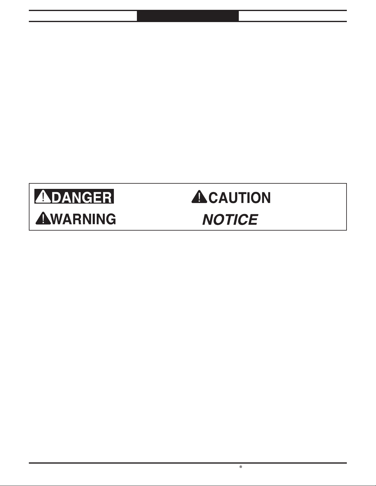
The signals used in this manual to identify hazard levels are as follows:
Owner’s Manual: All machinery and machining
Trained/Supervised Operators Only: Untrained
SAFETY
SAFETY
For Machines Mfd. Since 10/21
Understanding Risks of Machinery
Death or catastrophic
harm WILL occur.
Death or catastrophic
harm COULD occur.
Moderate injury or fi re
MAY occur.
Machine or property
damage may occur.
Basic Machine Safety
equipment presents serious injury hazards
to untrained users. To reduce the risk of
injury, anyone who uses THIS item MUST
read and understand this entire manual
before starting.
Personal Protective Equipment:
servicing this item may expose the user
to fl ying debris, dust, smoke, dangerous
chemicals, or loud noises. These hazards
can result in eye injury, blindness, longterm respiratory damage, poisoning,
cancer, reproductive harm or hearing loss.
Reduce your risks from these hazards
by wearing approved eye protection,
respirator, gloves, or hearing protection.
Operating or
users can seriously injure themselves
or bystanders. Only allow trained and
properly supervised personnel to operate
this item. Make sure safe operation
instructions are clearly understood. If
electrically powered, use padlocks and
master switches, and remove start switch
keys to prevent unauthorized use or
accidental starting.
Guards/Covers:
moving parts during operation may cause
severe entanglement, impact, cutting,
or crushing injuries. Reduce this risk by
keeping any included guards/covers/doors
installed, fully functional, and positioned
for maximum protection.
Accidental contact with
-8-
Page 17

South Bend Tools
For Machines Mfd. Since 10/21 Model SB1118
Entanglement: Loose clothing, gloves, neckties,
Chuck Keys or Adjusting Tools: Tools used to
SAFETY
jewelry or long hair may get caught in
moving parts, causing entanglement,
amputation, crushing, or strangulation.
Reduce this risk by removing/securing
these items so they cannot contact moving
parts.
Mental Alertness: Operating this item with
reduced mental alertness increases the
risk of accidental injury. Do not let a
temporary influence or distraction lead to a
permanent disability! Never operate when
under the influence of drugs/alcohol, when
tired, or otherwise distracted.
Safe Environment:
powered equipment in a wet environment
may result in electrocution; operating near
highly fl ammable materials may result in a
fi re or explosion. Only operate this item in
a dry location that is free from fl ammable
materials.
Electrical Connection: With electrically
powered equipment, improper connections
to the power source may result in
electrocution or fire. Always adhere to all
electrical requirements and applicable
codes when connecting to the power source.
Have all work inspected by a qualified
electrician to minimize risk.
Disconnect Power: Adjusting or servicing
electrically powered equipment while it
is connected to the power source greatly
increases the risk of injury from accidental
startup. Always disconnect power
BEFORE any service or adjustments,
including changing blades or other tooling.
Operating electrically
adjust spindles, chucks, or any moving/
rotating parts will become dangerous
projectiles if left in place when the machine
is started. Reduce this risk by developing
the habit of always removing these tools
immediately after using them.
Work Area:
the risks of accidental injury. Only operate
this item in a clean, non-glaring, and welllighted work area.
Properly Functioning Equipment:
maintained, damaged, or malfunctioning
equipment has higher risks of causing
serious personal injury compared to
those that are properly maintained.
To reduce this risk, always maintain
this item to the highest standards and
promptly repair/service a damaged or
malfunctioning component. Always follow
the maintenance instructions included in
this documentation.
Unattended Operation:
equipment that is left unattended while
running cannot be controlled and is
dangerous to bystanders. Always turn the
power OFF before walking away.
Health Hazards: Certain cutting fluids and
lubricants, or dust/smoke created when
cutting, may contain chemicals known to
the State of California to cause cancer,
respiratory problems, birth defects,
or other reproductive harm. Minimize
exposure to these chemicals by wearing
approved personal protective equipment
and operating in a well ventilated area.
Clutter and dark shadows increase
Poorly
Electrically powered
Secure Workpiece/Tooling:
cutting tools, or rotating spindles can
become dangerous projectiles if not
secured or if they hit another object during
operation. Reduce the risk of this hazard
by verifying that all fastening devices are
properly secured and items attached to
spindles have enough clearance to safely
rotate.
Loose workpieces,
Diffi cult Operations:
operations with which you are unfamiliar
increases the risk of injury. If you
experience difficulties performing the
intended operation, STOP! Seek an
alternative method to accomplish the
same task, ask a qualified expert how the
operation should be performed, or contact
our Technical Support for assistance.
Attempting difficult
-9-
Page 18

South Bend Tools
Model SB1118
Amputation, serious cuts, entanglement, or death can occur from contact with rotating cutterhead or
other moving parts! Flying chips can cause eye injuries or blindness. Workpieces or knives thrown
by cutterhead can strike nearby operator or bystanders with deadly force. To reduce the risk of these
hazards, operator and bystanders MUST completely heed hazards and warnings below.
Kickback:
Avoid Contact with Moving Parts:
Dull/Damaged Knives/Inserts:
Inspecting Stock:
Body Placement:
Grain Direction:
SAFETY
Additional Planer Safety
For Machines Mfd. Since 10/21
Know how to reduce the risk of
kickback and kickback-related injuries.
“Kickback” occurs during the operation
when the workpiece is ejected back from the
infeed side of the machine at a high rate
of speed. Kickback is commonly caused by
poor workpiece selection, unsafe feeding
techniques, or improper machine setup/
maintenance. Kickback injuries typically
occur as follows: (1) operator/bystanders
are struck by the workpiece, resulting in
impact injuries (i.e., blindness, broken bones,
bruises, death); (2) operator’s hands are
pulled into the machine from the outfeed
side, resulting in amputation or severe
lacerations.
Never remove
guards/covers or reach inside the planer
during operation or while connected to
power. You could be seriously injured if you
accidentally touch the spinning cutterhead
or get entangled in moving parts. If a
workpiece becomes stuck or sawdust removal
is necessary, turn planer OFF, allow
cutterhead to stop, and disconnect power
before clearing.
Only use sharp,
undamaged knives/inserts. Dull or damaged
knives/inserts increase the risk of kickback.
To reduce the risk of kickback
injuries or machine damage, thoroughly
inspect and prepare the workpiece before
cutting. Verify workpiece is free of nails,
staples, loose knots, or foreign material.
Workpieces with minor warping should be
jointed first or planed with the cupped side
facing the table.
Stand to one side of planer
during the entire operation to avoid getting
hit if kickback occurs.
Planing across the grain is hard
on the planer and may cause kickback. Plane
in the same direction or at a slight angle
with the wood grain.
Planing Correct Material: Only plane natural
wood stock with this planer. DO NOT
plane MDF, OSB, plywood, laminates
or other synthetic materials that can
break up inside the planer and be ejected
towards the operator.
Looking Inside Planer: Wood chips fly around
inside the planer at a high rate of speed
during operation. To avoid injury from
flying material, DO NOT look inside
planer during operation.
Cutting Limitations: To reduce the risk of
kickback hazards or damage to the
machine, do not exceed the maximum
depth of cut or minimum board length and
thickness found in the Data Sheet. Only
feed one board at a time.
Infeed Roller Clearance: The infeed roller
is designed to pull material into the
spinning cutterhead. To reduce the risk
of entanglement, keep hands, clothing,
jewelry, and long hair away from the
infeed roller during operation.
Feed Workpiece Properly: To reduce the risk
of kickback, never start planer with
workpiece touching cutterhead. Allow
cutterhead to reach full speed before
feeding, and do not change feed speed
during cutting operation.
Workpiece Support: To reduce the risk of
kickback, always make sure workpiece
can move completely across table without
rocking or tipping. Use auxiliary support
stands for long stock.
Secure Knives/Inserts: Loose knives or
improperly set inserts can become
dangerous projectiles or cause machine
damage. Always verify knives/inserts
are secure and properly adjusted before
operation.
-10-
Page 19

South Bend Tools
For Machines Mfd. Since 10/21 Model SB1118
PREPARATION
PREPARATION
Preparation Overview Required for Setup
The purpose of the preparation section is to help
you prepare your machine for operation. The list
below outlines the basic process. Specific steps
for each of these points will be covered in detail
later in this section.
The typical preparation process is as follows:
1. Unpack the machine and inventory the
contents of the box/crate.
Clean the machine and its components.
2.
3. Identify an acceptable location for the
machine and move it to that location.
Level the machine using the pre-installed
4.
machine mounts.
Assemble the loose components and make
5.
any necessary adjustments or inspections to
ensure the machine is ready for operation.
Connect the machine to the power source.
6.
7. Test run the machine to make sure it
functions properly and is ready for operation.
The items listed below are required to
successfully set up and prepare this machine for
operation.
For Lifting
• A forklift or other power lifting device rated
for the weight of the machine.
• Lifting straps or chains (rated for at least
2500 lbs.)
For Power Connection
• A power source that meets the minimum circuit requirements for this machine. (Refer to
the Power Supply Requirements on Page
12 for details.)
For Assembly
• Safety Glasses (for each person)
• Straightedge 4'
• Dust Collection System
• 6" Dust Hose
• 6" Hose Clamp
• Disposable Rags
• Disposable Gloves
• Cleaner/Degreaser
• Electrical Tape
• Assistant
• Phillips Head Screwdriver #2
• Open-End Wrenches 19, 24mm
• Hex Wrenches 2.5, 6mm
• Level
• D Battery
• ISO 150 Gear Oil
• Wrench or Socket 10mm
-11-
Page 20
South Bend Tools
Model SB1118
Before installing the machine, consider the
availability and proximity of the required power
supply circuit. If an existing circuit does not meet
the requirements for this machine, a new circuit
must be installed.
To minimize the risk of electrocution, fire,
or equipment damage, installation work and
electrical wiring must be done by a
or qualified service personnel
applicable electrical codes and safety standards.
Note: The circuit requirements in this manual
are for
machine will be running at a time. If this
machine will be connected to a shared circuit
where multiple machines will be running at
the same time, consult a qualified electrician to
ensure the circuit is properly sized.
A power supply circuit includes all electrical
equipment between the main breaker box or fuse
panel in your building and the incoming power
connections inside the machine. This circuit
must be safely sized to handle the full-load
current that may be drawn from the machine for
an extended period of time. (If this machine is
connected to a circuit protected by fuses, use a
time delay fuse marked D.)
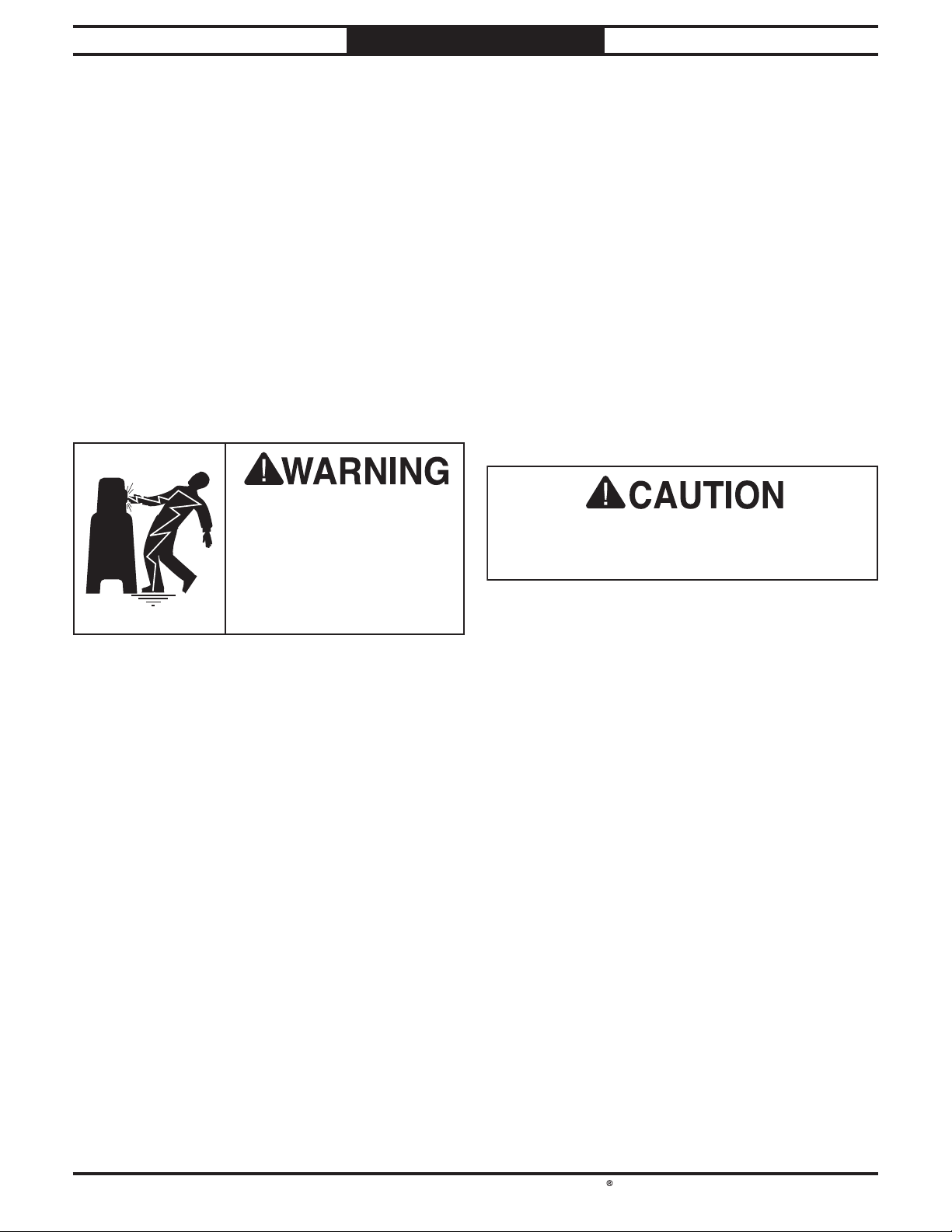
This machine must be grounded! In the event
of
grounding provides a path of least resistance
for electric current
electric shock.
Improper connection of the equipment-grounding
wire can result in a risk of electric shock. The
wire with green insulation (with or without
yellow stripes) is the equipment-grounding wire.
If repair or replacement of the power cord or
plug is necessary, do not connect the equipmentgrounding wire to a live (current carrying)
terminal.
Check with an electrician or qualifi ed service
personnel if you do not understand these
grounding requirements, or if you are in doubt
about whether the tool is properly grounded.
If you ever notice that a cord or plug is
damaged or worn, disconnect it from power, and
immediately replace it with a new one.
The full-load current rating is the amperage
a machine draws at 100% of the rated output
power. On machines with multiple motors, this is
the amperage drawn by the largest motor or sum
of all motors and electrical devices that might
operate at one time during normal operations.
The full-load current is not the maximum
amount of amps that the machine will draw. If
the machine is overloaded, it will draw additional
amps beyond the full-load rating.
If the machine is overloaded for a sufficient
length of time, damage, overheating, or fire may
result—especially if connected to an undersized
circuit. To reduce the risk of these hazards,
avoid overloading the machine during operation
and make sure it is connected to a power supply
circuit that meets the requirements in the
following section.
Power supply requirements
PREPARATION
For Machines Mfd. Since 10/21
Power Supply
Requirements
Availability
in accordance with
Electrocution or fire may
occur if machine is not
correctly grounded and
attached to the power
supply. Use a qualified
electrician to ensure a safe
power connection.
Circuit Information
a dedicated circuit—where only one
n electrician
For your own safety and protection of property,
consult an electrician if you are unsure about
wiring practices or applicable electrical codes.
Grounding Requirements
Full-Load Current Rating
Full-Load Rating at 220V ................... 45 Amps
Full-Load Rating at 440V
-12-
................ 26.5 Amps
certain types of malfunctions or breakdowns,
in order to reduce the risk of
Page 21
South Bend Tools
For Machines Mfd. Since 10/21 Model SB1118
This machine can be converted to operate on
a
Voltage Conversion
this
have a verified ground and meet the
requirements:
Serious injury could occur if you connect
This machine is prewired to operate on a power
supply circuit that has a verified ground and
meets the following requirements:
PREPARATION
Phase Converters
DO NOT use a static phase converter to create
3-phase power—it can quickly decrease the life
of electrical components on this machine. If you
must use a phase converter, only use a rotary
phase converter.
the machine to power before completing the
setup process. DO NOT connect to power until
instructed later in this manual.
Circuit Requirements for 220V
Nominal Voltage ..................... 220V/230V/240V
Cycle
Phase
Circuit Rating....................................... 50 Amps
Connection
.............................................................60 Hz
....................................................... 3-Phase
..... Hardwire with Locking Switch
Connection Type
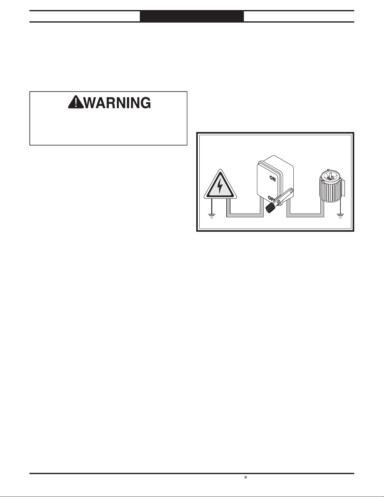
A permanently connected (hardwired) power
supply is typically installed with wires running
through mounted and secured conduit. A
disconnecting means, such as a locking switch
(see Figure 5), must be provided to allow the
machine to be disconnected (isolated) from the
power supply when required. This installation
must be performed by an electrician in
accordance with all applicable electrical codes
and ordinances.
LOCKING
DISCONNECT SWITCH
Power Source
Conduit
Ground Ground
Conduit
Machine
Circuit Requirements for 440V
440V power supply. To do this, follow the
instructions included in
manual. The intended 440V circuit must
following
Nominal Voltage ............................... 440V/480V
Cycle
Phase
Circuit Rating....................................... 30 Amps
Connection
.............................................................60 Hz
....................................................... 3-Phase
..... Hardwire with Locking Switch
Extension Cords
Since this machine must be permanently
connected to the power supply, an extension cord
cannot be used.
-13 -
Page 22
South Bend Tools
Model SB1118
PREPARATION
Converting Voltage to 440V
The Model SB1118 can be converted to 440V
operation. This conversion consists of: 1)
Disconnecting the planer from power, 2) rewiring
the transformers, 3) replacing the overload relays,
and (4) rewiring the table and cutterhead motors
for 440V operation.
For Machines Mfd. Since 10/21
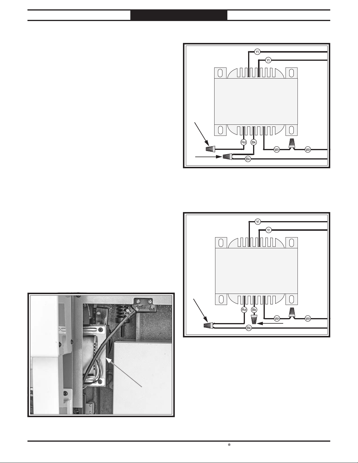
4. Loosen two wire nuts indicated in Figure 7.
0 (Yellow) 110 (Yellow)
Transformer
All wiring changes must be inspected by a
qualified electrician or service personnel before
the saw is connected to the power source. If,
at any time during this procedure you need
assistance, call Grizzly Tech Support at (570)
546-9663.
Items Needed Qty
Phillips Head Screwdriver #2 ...............................1
Hex Wrenches 4, 5mm
Overload Relay SDE RA-30
Overload Relay SDE RA-20
Electrical Tape
...................................... As Needed
.................................... 1 Ea
.................................. 1
.................................. 1
To convert SB1118 to 440V operation:
1. DISCONNECT MACHINE FROM POWER!
2. Remove electrical cabinet access panel on
right-hand side of machine.
3. Locate transformer (see Figure 6) mounted
outside electrical box.
440 (Red) 220 (Black) 0 (White)
5. Move black wire as indicated in Figure 8,
then tighten both wire nuts and wrap with
electrical tape.
0 (Yellow) 110 (Yellow)
Transformer
440 (Red) 220 (Black) 0 (White)
-14-
Page 23
South Bend Tools
For Machines Mfd. Since 10/21 Model SB1118
PREPARATION
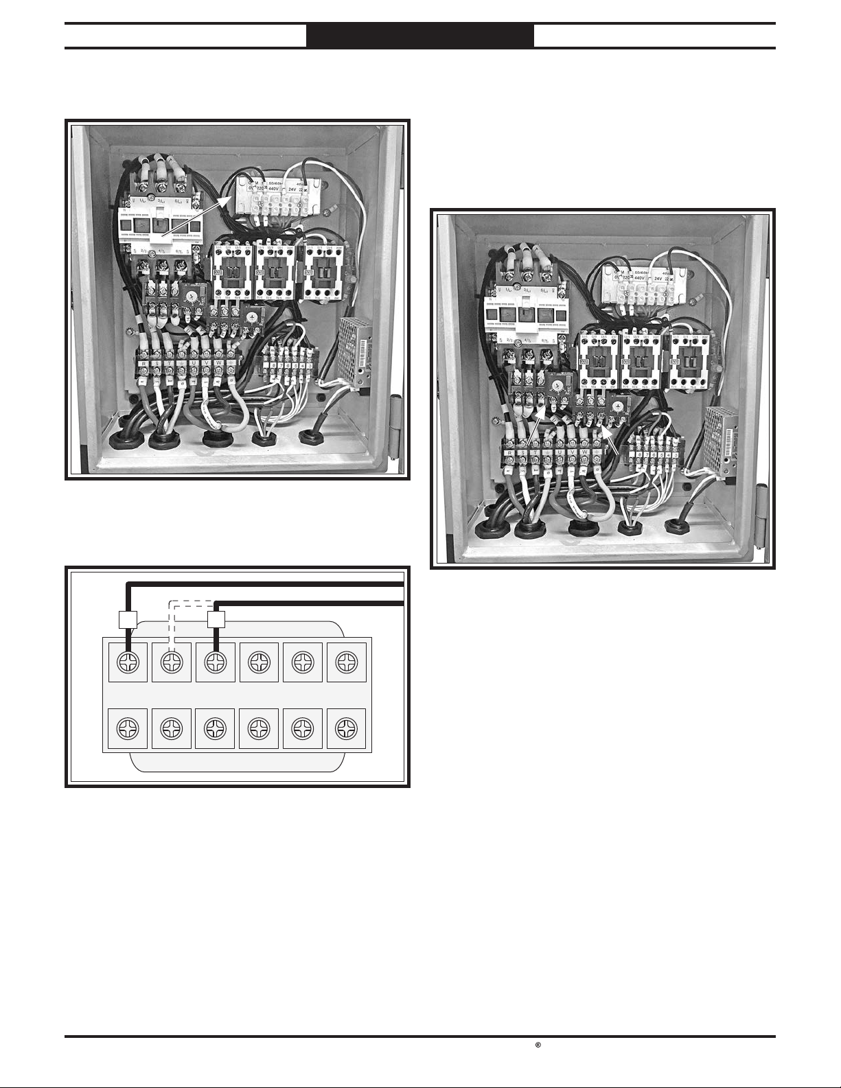
6. Open electrical box and locate transformer
(see Figure 9).
8. Remove cutterhead overload relay (see
Figure 11) and replace with SDE RA-30
overload relay. Set amperage dial to 18.5A.
9. Remove table overload relay (see Figure 11)
and replace with SDE RA-20 overload relay.
Set amperage dial to 1.2A.
7. Move R wire from 220V terminal to 440V
terminal (see Figure 10).
T
0V 0V 24V 220V
220V 440V
R
10. Close electrical box, and replace access panel
removed in Step 2.
11. Remove front access panel and motor access
panel, and rewire main motor and table
motor for 440V operation (refer to motor
wiring diagrams on Page 65).
12. Replace access panels removed in Step 11.
Note: If the diagram included on the motor
conflicts with the one in this manual, the
motor may have changed since the manual
was printed. Use the diagram provided on
the motor.
-15 -
Page 24
South Bend Tools
Model SB1118
This item was carefully packaged to prevent
damage during transport. If you discover any
damage, please immediately call Customer
Service at (360) 734-1540 for advice. You may
need to file a freight claim, so take pictures and
save all the containers and packing materials for
possible inspection by the carrier or its agent.
PREPARATION
Unpacking
Inventory
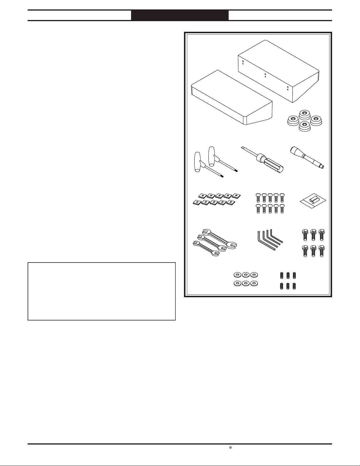
Inventory (Figure 12) Qty
A. Planer (Not Shown) ........................................1
Extension Tables ............................................ 2
B.
Machine Mounting Feet.................................4
C.
T-Handle Torx Wrenches T-25 ...................... 2
D.
Flat Head Screwdriver 1⁄4" .............................1
E.
Bed Roller Height Handle ............................. 1
F.
Indexable Carbide Inserts 15 x 15 x 2.5mm ..... 10
G.
Flat Head Torx Screws #10-32 x 1⁄2" ............ 10
H.
Spare Fuses 2A 250V ..................................... 2
I.
Open-End Wrenches ........................................
J.
–12/14, 17/19, 22/24mm ........................... 1 Ea
Hex Wrenches 3, 4, 5, 8mm ..................... 1 Ea
K.
Hex Bolts M12-1.75 x 50 (Ext. Tables) ......... 6
L.
Flat Washers 12mm (Ext. Tables) ................ 6
M.
Set Screws M10-1.5 x 20 (Ext. Tables) ......... 6
N.
For Machines Mfd. Since 10/21
B
C
D E F
G H I
J K L
NOTICE
If you cannot fi nd an item on this list, carefully
check around/inside the machine and
packaging materials. Often, these items get
lost in packaging materials while unpacking or
they are pre-installed at the factory.
-16 -
M N
Page 25
South Bend Tools
For Machines Mfd. Since 10/21 Model SB1118
The unpainted surfaces are coated
with a heavy-duty rust preventative that
prevents corrosion during shipment and
The benefi t of this rust preventative is that it
works very well. The downside is that it
time-consuming
Be patient and do a careful job when
and removing the rust preventative
you spend doing this will reward you with
smooth
for the proper care of
Although there are many ways to successfully
remove the rust preventative, the
process works well in most situations
Before cleaning, gather the following:
• Disposable
• Cleaner/degreaser
• Safety glasses & disposable gloves
Note:
WD•40 can be used to remove rust preventative.
Before using these products, though, test them
on an inconspicuous area of a painted surface to
make sure they will not damage it.
GAS
PREPARATION
Cleaning & Protecting
at the factory
to thoroughly remove.
-sliding parts and a better appreciation
the unpainted surfaces.
rags
(certain citrus-based
degreasers work extremely well and they
have non-toxic fumes)
Automotive degreasers, mineral spirits, or
. The time
following
storage.
can be
cleaning
.
Avoid chlorine-based solvents, such as
acetone or brake parts cleaner that may
damage painted surfaces. Always follow the
manufacturer’s instructions when using any
type of cleaning product.
Basic steps for removing rust preventative:
1. Put on safety glasses and disposable gloves.
2. Coat all surfaces that have rust preventative
with a liberal amount of your cleaner or
degreaser and let them soak for a few
minutes.
3. Wipe off the surfaces. If your cleaner or
degreaser is effective, the rust preventative
will wipe off easily.
Note: To clean off thick coats of rust
preventative on fl at surfaces, such as beds
or tables, use a PLASTIC paint scraper to
scrape off the majority of the coating before
wiping it off with your rag. (Do not use a
metal scraper or it may scratch the surface.)
4. Repeat Steps 2–3 as necessary until clean,
then coat all unpainted surfaces with a
quality metal protectant or light oil to
prevent rust.
Gasoline and petroleum
products have low flash
points and can explode
or cause fire if used for
cleaning. Avoid using these
products to remove rust
preventative.
Many cleaning solvents are
toxic if inhaled. Minimize
your risk by only using
these products in a well
ventilated area.
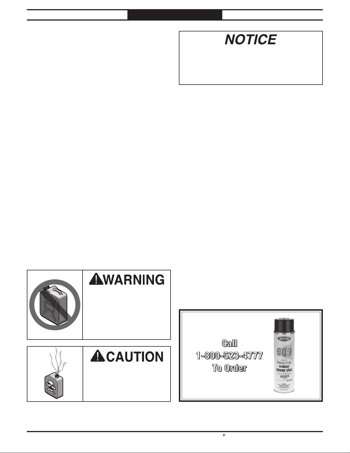
T23692—Orange Power Degreaser
A great product for removing the waxy shipping
grease from the non-painted parts of the
machine during clean up.
-17-
Page 26
South Bend Tools
Model SB1118
Weight Load
equipment that may be installed on the machine,
Physical Environment
The physical environment where your machine
is operated is important for safe operation and
longevity of
machine in a dry environment that is free from
excessive moisture, hazardous
chemicals, airborne abrasives, or extreme
conditions. Extreme conditions for this type
of machinery are generally those where the
ambient temperature
104°F; the relative humidity
of
is subject to vibration, shocks, or bumps.
Electrical Installation
Place this machine near an existing power
source. Make sure all power cords are protected
from traffic, material handling, moisture,
chemicals, or other hazards. Make sure to leave
access to a means of disconnecting the power
source or engaging a lockout/tagout device.
Lighting
Lighting around the machine must be adequate
enough to perform operations safely. Shadows,
glare, or strobe effects that may distract or
impede the operator must be eliminated.
PREPARATION
For Machines Mfd. Since 10/21
Location
Physical Environment
Electrical Installation
Lighting
Weight Load
Space Allocation
20–95% (non-condensing); or the environment
parts. For best results, operate this
or flammable
is outside the range of 41°–
is outside the range
Refer to the Machine Specifications for the
weight of your machine. Make sure that the
surface upon which the machine is placed will
bear the weight of the machine, additional
and the heaviest workpiece that will be used.
Additionally, consider the weight of the operator
and any dynamic loading that may occur when
operating the machine.
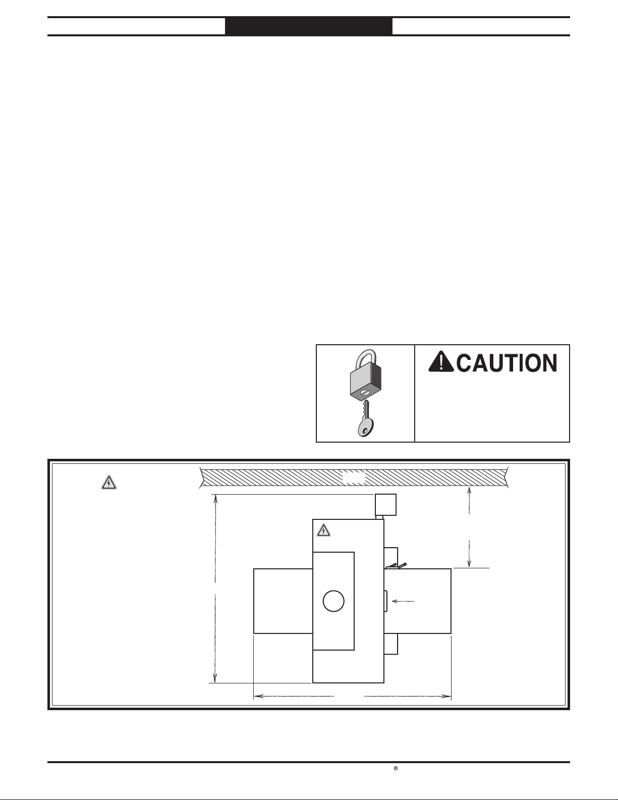
Space Allocation
Consider the largest size of workpiece that will
be processed through this machine and provide
enough space around the machine for adequate
operator material handling or the installation
of auxiliary equipment. With permanent
installations, leave enough space around
the machine to open or remove doors/covers
as required by the maintenance and service
described in this manual.
Electrical
=
Connection
57"
Children or untrained
people may be seriously
Wall
Dust
Po r t
54½"
injured by this machine.
Only install in an access
restricted location.
Min. 30"
for Maintenance
Feed
Direction
-18 -
Page 27
South Bend Tools
For Machines Mfd. Since 10/21 Model SB1118
PREPARATION
Lifting & Moving
This machine and its
parts are heavy! Serious
personal injury may occur
if safe moving methods are
not used. To reduce the
risk of a lifting or dropping
injury, ask others for help
and use power equipment.
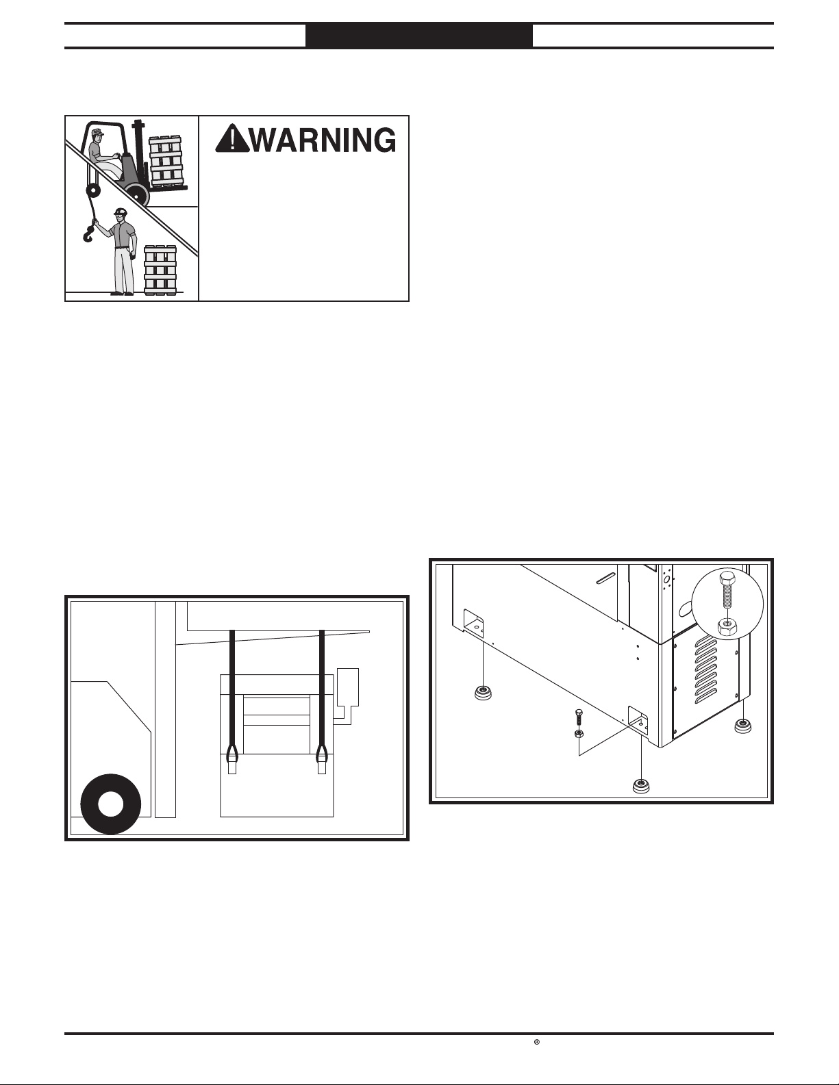
The Model SB1118 requires the use of lifting
equipment such as a forklift, engine hoist, or
boom crane. DO NOT attempt to lift or move the
planer without necessary assistance from other
people. Each piece of lifting equipment must be
rated for at least 2500 lbs. to support dynamic
loads that may be applied while lifting.
To lift and move planer:
1. Remove sides and top of shipping crate.
2. Place lifting straps under lifting hooks (see
Figure 15). Make sure straps are not in
contact with any controls or handles.
Leveling
The SB1118 comes with four cast-iron feet and
four pre-installed hex bolts and hex nuts at each
corner of the base for leveling the machine.
This type of mount offers certain advantages,
such as ease of installation and easy leveling. It
also makes it easier to move the machine later.
The disadvantage of this type of mount is that
the machine can shift or move over time. For this
reason, electrical codes in your region may limit
their use since the machine must be hardwired to
the power source. Consult a qualified electrician
to determine local requirements.
Tools Needed Qty
Open-End Wrenches 24mm .................................. 2
Machinist's Level
To level machine:
Ensure (4) pre-installed M16-2 x 55 hex bolts
1.
and M16-2 hex nuts (see Figure 16) are
threaded into base approximately the same
amount.
..................................................1
Unbolt planer from pallet.
3.
4. Slowly raise planer, and move to prepared
location.
x 4
With machine raised off floor, position (4)
2.
cast-iron feet beneath hex bolts and slowly
lower machine onto feet.
Level machine front to back and side to side,
3.
then tighten hex nuts to secure position.
-19 -
Page 28
South Bend Tools
Model SB1118
PREPARATION
For Machines Mfd. Since 10/21
Anchoring to Floor
Number of Mounting Holes ..........................................4
Size of Mounting Hardware
Anchoring machine to the floor prevents tipping
or shifting that may occur during operation with
large/heavy workpieces.
If machine is installed in a commercial or
workplace setting, or if it is permanently
connected (hardwired) to the power supply, local
codes may require that it be anchored to the floor.
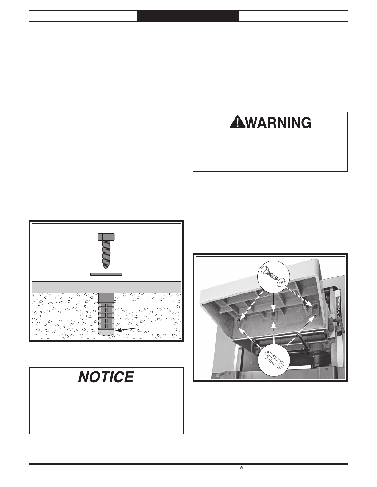
Mounting to Concrete Floors
Lag shield anchors with lag screws (see below)
are a popular way to anchor machinery to a
concrete floor, because the anchors sit flush with
the floor surface, making it easy to unbolt and
move the machine later, if needed. However,
anytime local codes apply, you MUST follow the
anchoring methodology specified by the code.
.......................................1⁄2"
Assembly
This machine must be fully assembled before it
can be operated. Before beginning the assembly
process, refer to Required for Setup and gather
all listed items. To ensure the assembly process
goes smoothly, first clean any parts that are
covered or coated in heavy-duty rust preventative
(if applicable).
Straining or crushing injury may occur from
improperly lifting extension tables. To reduce
this risk, get help from other people or use
lifting equipment rated for weight of these
tables.
To assemble machine:
1. Attach each extension table to planer table
with (3) M12-1.75 x 50 hex bolts and 12mm
flat washers, as shown in Figure 18. Handtighten for now.
Lag Screw
Flat Washer
Machine Base
Lag Shield Anchor
Concrete
Drilled Hole
Shims may be required when mounting the
planer to the floor. If the floor is uneven and
you tighten the mounting bolts without shims,
you can crack the cast-iron base. Shim any
gaps between the base and the floor before
fully tightening the mounting bolts.
Thread (3) M10-1.5 x 20 set screws into each
2.
extension table (see Figure 18).
x 3
x 3
-20-
Page 29
South Bend Tools
For Machines Mfd. Since 10/21 Model SB1118
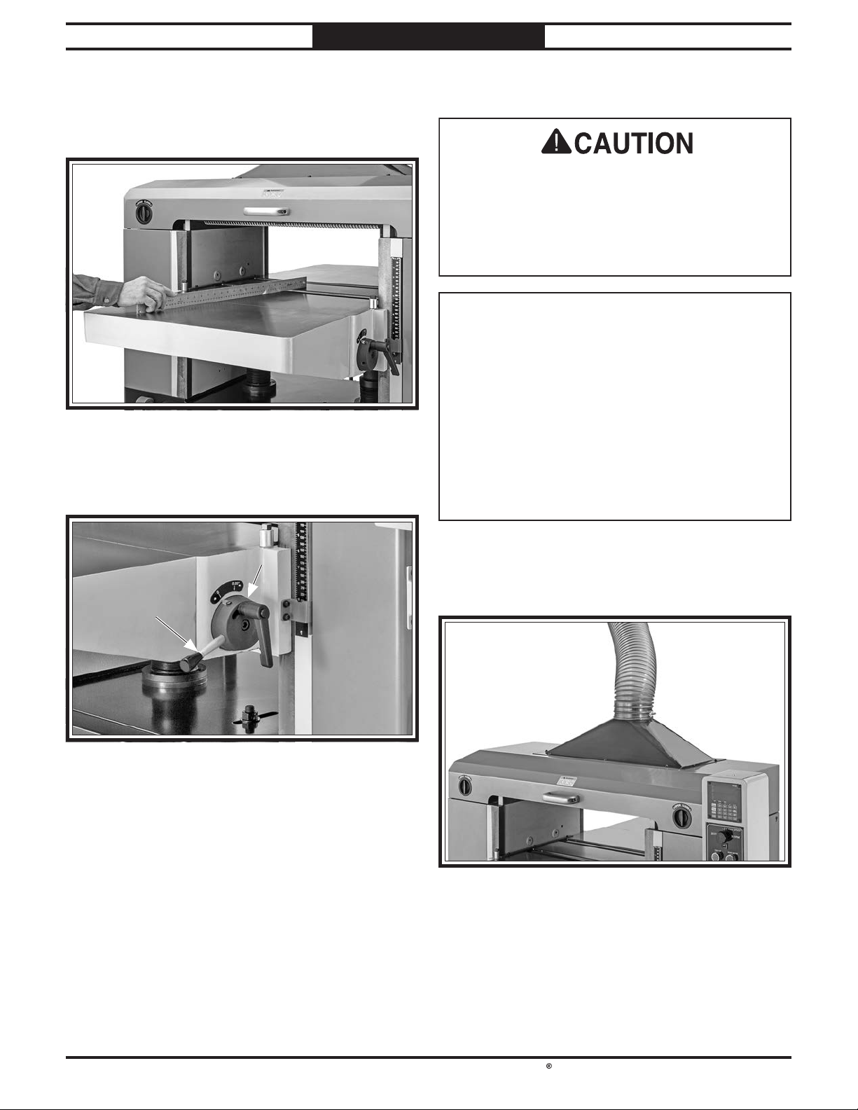
3. Using a straightedge as a guide (see Figure
19), rotate set screws installed in Step 2
until extension tables are level and flush
with planer table.
4. Install bed roller height handle (see Figure
20) in hub on right side of front extension
table.
PREPARATION
Dust Collection
This machine creates a lot of wood chips/
dust during operation. Breathing airborne dust
on a regular basis can result in permanent
respiratory illness. Reduce your risk by
wearing a respirator and capturing the dust
with a dust-collection system.
Minimum CFM at Dust Port: 600 CFM
Do not confuse this CFM recommendation with
the rating of the dust collector. To determine
the CFM at the dust port, you must consider
these variables: (1) CFM rating of the dust
collector, (2) hose type and length between the
dust collector and the machine, (3) number of
branches or wyes, and (4) amount of other open
lines throughout the system. Explaining how to
calculate these variables is beyond the scope of
this manual. Consult an expert or purchase a
good dust collection "how-to" book.
To connect machine to a dust collector:
1. Fit a 6" dust hose over dust port (see Figure
21), and secure in place with a hose clamp.
2.
Tug hose to make sure it does not come off.
Note: A tight fit is necessary and ensures
proper performance during operation.
-21-
Page 30
South Bend Tools
Model SB1118
PREPARATION
For Machines Mfd. Since 10/21
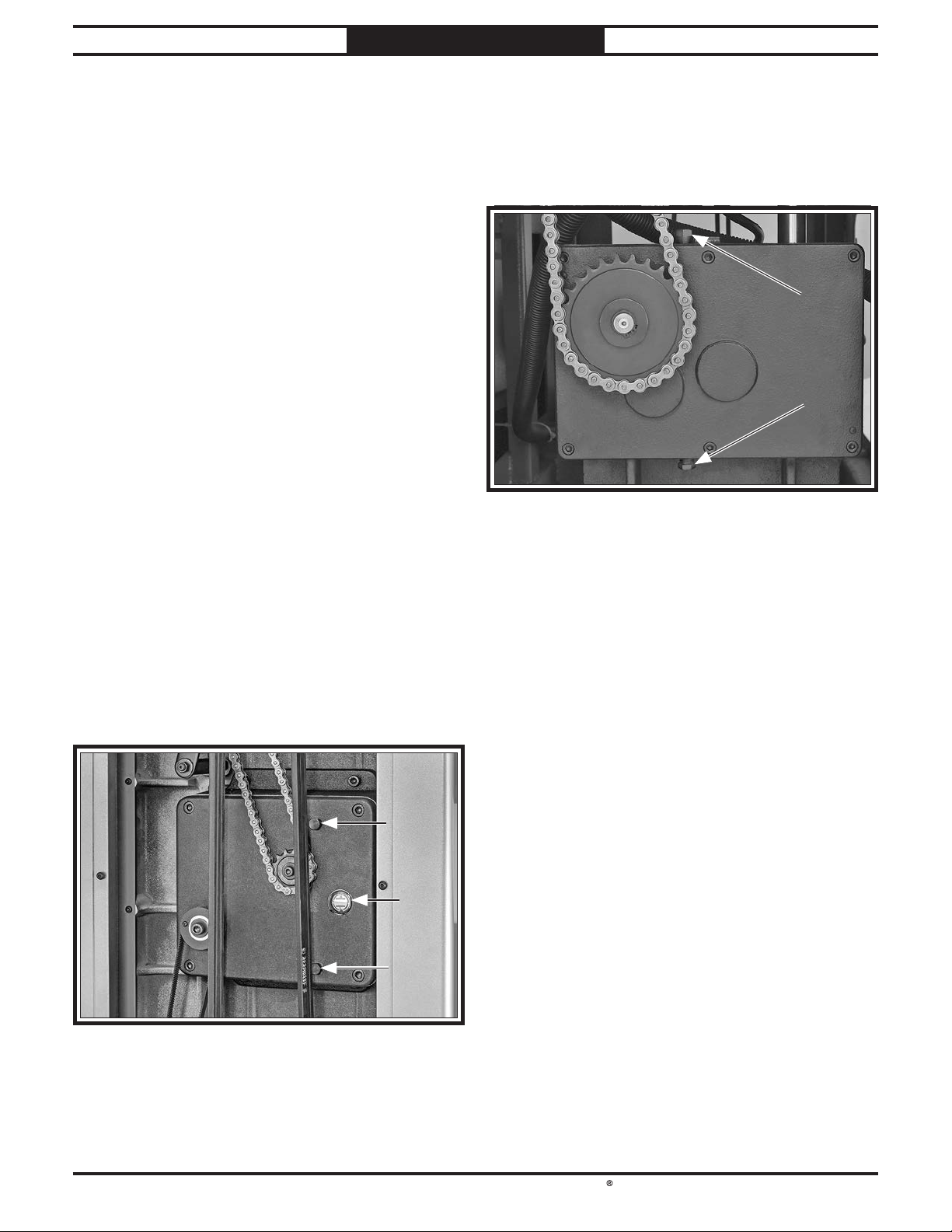
Checking Gearbox Oil Levels
Before starting the machine for the first time,
check the oil level in the cutterhead/feed gearbox
and the table gearbox. See Gearbox Oil on Page
41 for more information. DO NOT mix oil types.
Items Needed Qty
Open-End Wrench or Socket 14mm ..................... 1
Hex Wrenches 4, 6mm
Gear Oil 150 ISO
Cutterhead/Feed Gearbox
The gearbox has the proper amount of oil when
the sight glass is filled approximately halfway.
To check gearbox oil level:
1. Remove upper access panel on left-hand side
of machine.
Locate sight glass on front of gearbox (see
2.
Figure 22).
.................................... 1 Ea
................................... As Needed
Table Gearbox
Remove lower access panel on right-hand
1.
side of machine.
Remove gearbox oil fill plug (see Figure 23).
2.
3. Wipe clean 6mm hex wrench and insert
short end inside oil fill hole with inserted
end pointing down, then remove it.
— If sight glass is filled approximately
halfway, then gearbox oil level is okay.
— If sight glass is not filled approximately
halfway, then you need to add more oil.
Refer to Gearbox Oil on Page 41.
— If end of hex wrench is coated with oil,
then gearbox oil level is okay. Replace fill
plug and continue setup.
— If end of hex wrench is not coated with oil,
then you need to add more oil. Refer to
Gearbox Oil on Page 41 for instructions
on how to do this.
Note: We recommend that you replace the oil
in both gearboxes after the first 20 hours of
operation. This is a normal break-in procedure
and will help maximize the service life of the
machine by flushing away any particles from the
break-in and manufacturing process.
-22-
Page 31
South Bend Tools
For Machines Mfd. Since 10/21 Model SB1118
PREPARATION
Power Connection
Connecting power supply wires to machine
without first disconnecting power supply may
Electrocution or fire
may occur if machine is
ungrounded, incorrectly
connected to power, or
connected to an undersized
circuit. Use a qualified
electrician to ensure a safe
power connection.
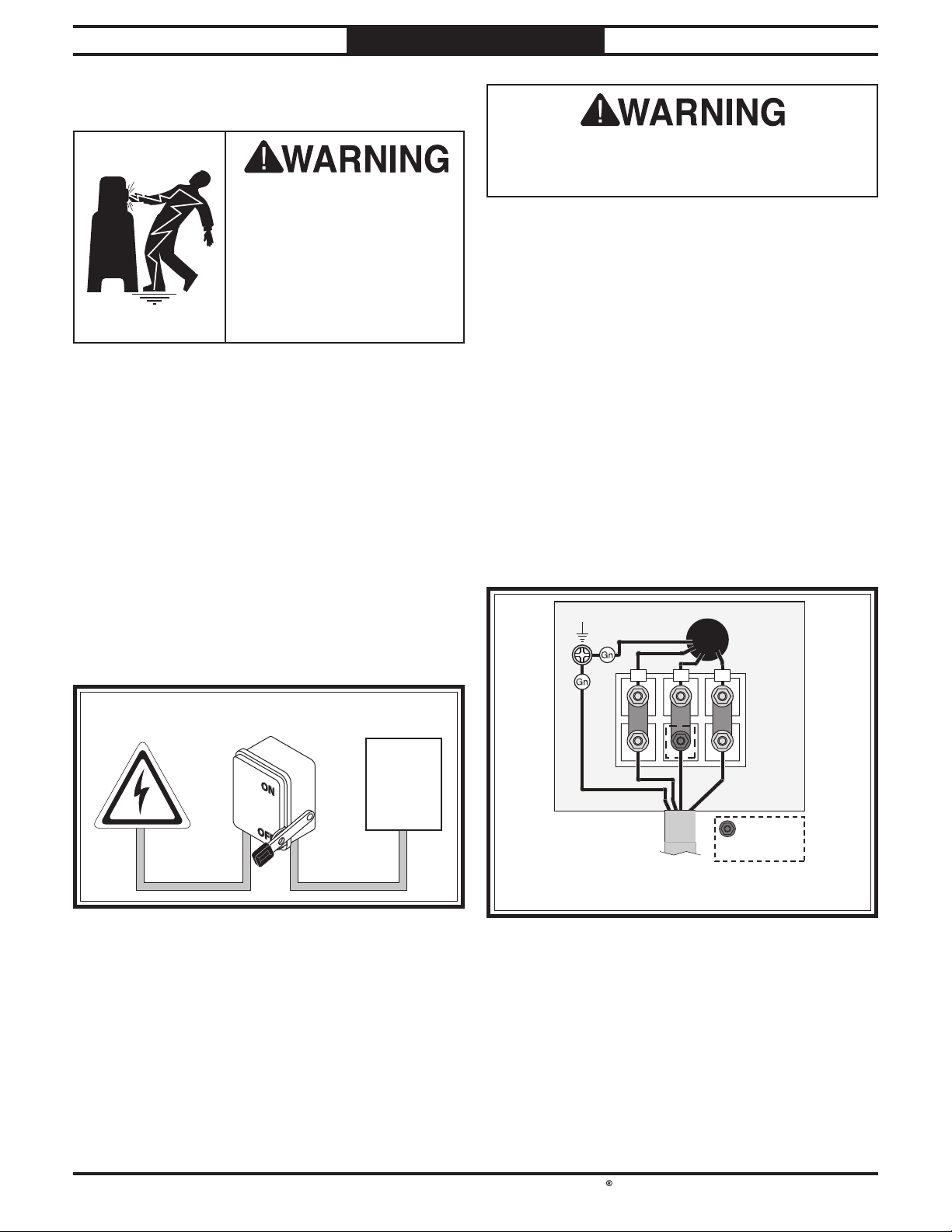
Hardwire setups require power supply lines to
be enclosed inside of conduit, which is securely
mounted and constructed in adherence to
applicable electrical codes.
A hardwire setup for this machine must be
equipped with a locking disconnect switch
as a means to disconnect the power during
adjustments or maintenance, which is a typical
requirement for many lock-out/tag-out safety
programs.
result in serious injury or death.
To connect power supply wires to machine:
1. Remove cover from power supply junction
box.
Insert incoming power wires through strain
2.
relief (see Figure 25) at bottom of junction
box, connect wires to terminals shown below,
tighten strain relief, then install junction box
cover.
Note: When using a phase converter, connect
the manufactured power leg or "wild wire"
to the terminal indicated in Figure 25).
This terminal can handle power fluctuation
because it is wired directly to the motor. The
other wires connect to the controls and must
be consistent to prevent damage.
Figure 24 shows a simple diagram of a hardwire
setup with a locking disconnect switch between
the power supply and the machine.
Locking
Power Source
Conduit Conduit
Due to the complexity required for planning,
bending, and installing the conduit necessary for
a code-compliant hardwire setup, an electrician
or other qualified person MUST perform this
type of installation.
Disconnect Switch
Machine
Ground
TSR
= For phase
converter wild
Incoming
220V/440V
3-PH Power
Shut off main power at power source circuit
3.
breaker and attach wires to locking shut-off
switch.
wire (if used)
-23-
Page 32
South Bend Tools
Model SB1118
PREPARATION
Test Run
After all preparation steps have been completed,
the machine and its safety features must be
tested to ensure correct operation. If you discover
a problem with the operation of the machine or
its safety components, do not operate it further
until you have resolved the problem.
Note: Refer to Troubleshooting on Page 56
for solutions to common problems. If you need
additional help, contact our Tech Support or
(360) 734-1540.
The test run consists of verifying the following:
• Power supply polarity is correct.
• Motors power up and run correctly.
• EMERGENCY STOP button works
correctly.
• Headstock cover safety switch works correctly.
• Table limit switches work correctly.
For Machines Mfd. Since 10/21
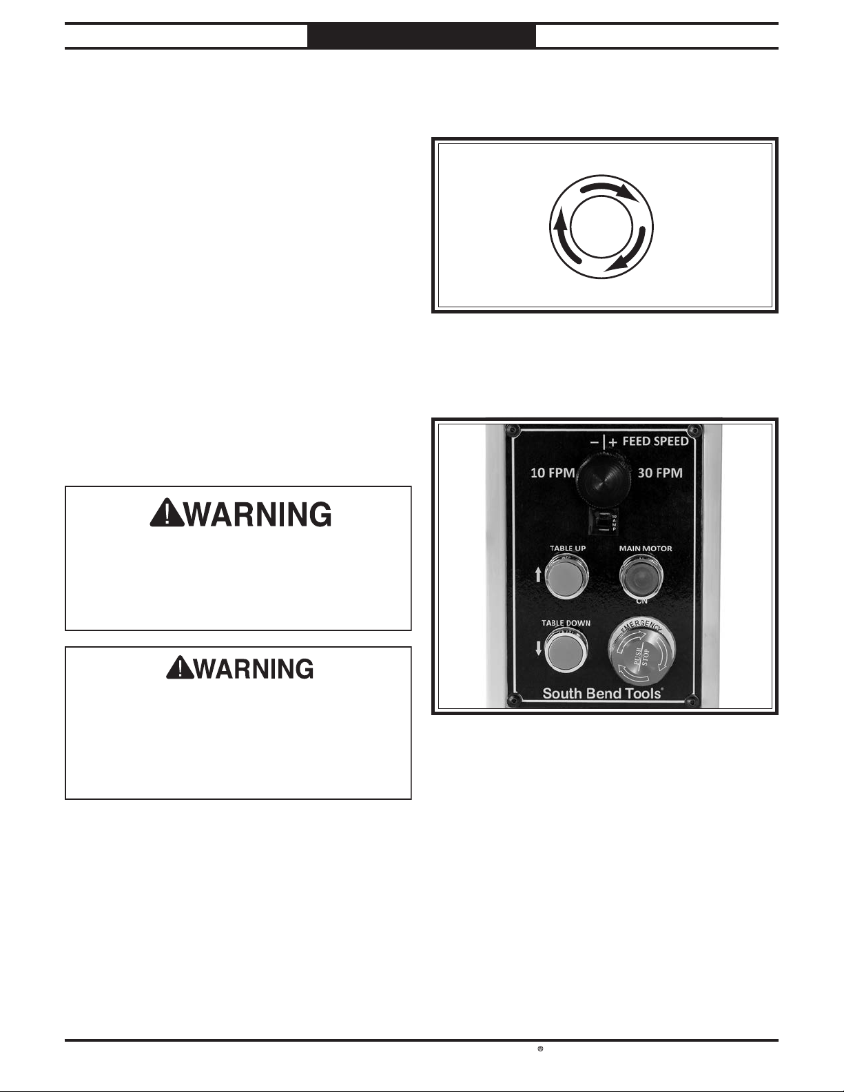
4. Twist EMERGENCY STOP button clockwise
until it pops out (see Figure 26). This resets
switch so machine can start.
s
i
w
t
T
t
e
s
e
R
o
T
C
l
o
c
k
w
i
z
e
STOP Button
Verify power supply is connected to machine
5.
with correct polarity by pressing TABLE UP
and TABLE DOWN buttons (see Figure 27).
Serious injury or death can result from using
this machine BEFORE understanding its
controls and related safety information. DO
NOT operate, or allow others to operate,
machine until the information is understood.
DO NOT start machine until all preceding
setup instructions have been performed.
Operating an improperly set up machine may
result in malfunction or unexpected results
that can lead to serious injury, death, or
machine/property damage.
To test run machine:
1. Clear all setup tools away from machine.
Push EMERGENCY STOP button.
2.
Connect machine to power supply.
3.
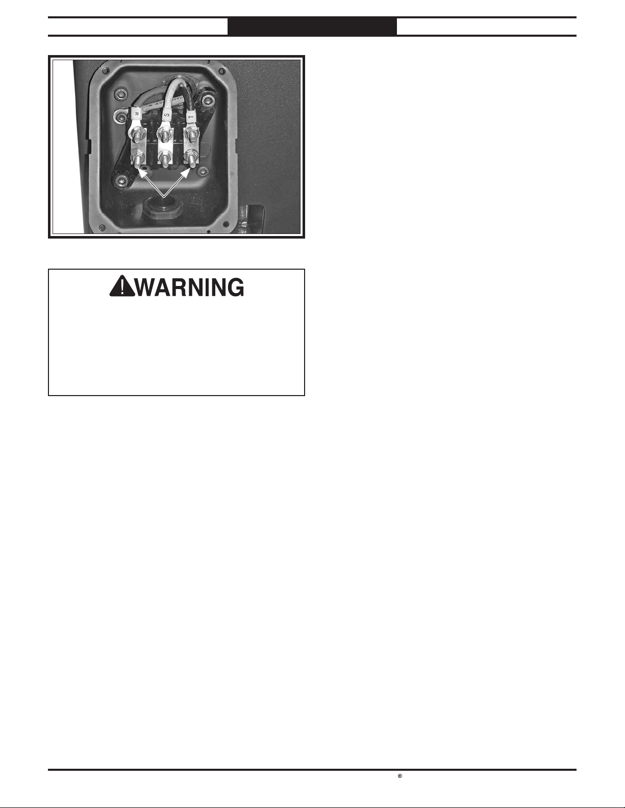
— If table moves in same direction as button
description, power supply polarity is
correct.
— If table moves in opposite direction as
button description, stop machine and
DISCONNECT FROM POWER! Swap
"R" and "T" wire positions in power
supply junction box (see Figure 28), and
reconnect machine to power.
-24-
Page 33
South Bend Tools
For Machines Mfd. Since 10/21 Model SB1118
You MUST verify that table moves in expected
direction according to buttons pressed on
control panel, otherwise all controls will
function in reverse. Cutterhead and feed
rollers MUST rotate in correct direction or
serious personal injury and machine damage
could occur.
PREPARATION
— If machine does not start, the
EMERGENCY STOP button safety
feature is working correctly.
— If machine does start (with EMERGENCY
STOP button pushed in), immediately
disconnect power to machine.
EMERGENCY STOP button safety
feature is not working correctly and must
be replaced before further using the
machine. Call Tech Support for help.
Reset EMERGENCY STOP button.
10.
11. Raise headstock cover approximately 4" and
press MAIN MOTOR button.
— If machine does not start, the headstock
cover safety switch is working correctly.
— If machine does start, immediately
disconnect power to machine. The
headstock cover safety switch is not
working correctly and must be replaced
before further using the machine. Call
Tech Support for help.
6. Press MAIN MOTOR button (see Figure 27)
to turn cutterhead motor and feed motor ON.
Verify motors start up and run smoothly
without any unusual vibrations or noises.
Slowly rotate FEED SPEED knob (see
7.
Figure 27) back and forth to test variable
feed speed function.
Press EMERGENCY STOP button (see
8.
Figure 27) to turn cutterhead motor and
feed motor OFF.
WITHOUT resetting EMERGENCY STOP
9.
button, try to start machine by pressing
MAIN MOTOR button. The motors should
not start.
Press and hold TABLE UP button. The table
12.
should stop just before making contact with
the headstock.
— If table does stop, the upper table limit
switch is working correctly.
— If table does not stop, immediately
disconnect power to machine. The upper
table limit switch is not working correctly
and must be replaced before further using
the machine. Call Tech Support for help.
Perform Step 12 on the TABLE DOWN
13.
button.
Congratulations! Test Run is complete!
-25-
Page 34

South Bend Tools
Model SB1118
PREPARATION
Inspections & Adjustments
The following list of adjustments were performed
at the factory before your machine was shipped:
• Chip Breaker Height ....................... Page 46
• Pressure Bar Height & Tension ...Page 46
• Infeed/Outfeed Roller Height .......Page 46
• Roller Spring Tension ....................Page 49
• Table Height Chain Tension .........Page 53
• Table Parallelism ............................. Page 52
Be aware that machine components can shift
during the shipping process. Pay careful
attention to these adjustments as you test run
your machine. If you find that the adjustments
are not set according to the procedures in this
manual or your personal preferences, re-adjust
them.
For Machines Mfd. Since 10/21
After approximately 16 hours of operation,
V-belts will stretch and seat into pulley
grooves and need to be properly tensioned to
ensure good power transfer from motor and
avoid severely reducing life of V-belts. Refer to
Tensioning/Replacing V-Belts on Page 44 for
detailed instructions.
-26-
Page 35
South Bend Tools
For Machines Mfd. Since 10/21 Model SB1118
The purpose of this overview is to provide
the novice machine operator with a basic
understanding of how the machine is used during
operation, so they can more easily understand
the controls discussed later in this manual.
Note:
it is not intended to be an instructional guide for
performing actual machine operations. To learn
more about specifi c operations and machining
techniques, seek training from people experienced
with this type of machine, and do additional
research outside of this manual by reading "howto" books, trade magazines, or websites.
OPERATION
OPERATION
To complete a typical operation, the operator
Operation Overview
does the following:
1. Examines workpiece to make sure it is
suitable for planing.
Puts on safety glasses or face shield, a
2.
respirator, and hearing protection.
Due to the generic nature of this overview,
To reduce the risk of
serious injury when using
this machine, read and
understand this entire
manual before beginning
any operations.
To reduce risk of short and
long term injury, wear eye,
ear, and lung protection
when using this machine.
If you are not experienced with this type
of machine, WE STRONGLY RECOMMEND
that you seek additional training outside of
this manual. Read books/magazines or get
formal training before beginning any projects.
Regardless of the content in this section,
South Bend Tools will not be held liable for
accidents caused by lack of training.
Places workpiece on table with flat side down
3.
and correctly adjusts bed roller height and
table elevation for workpiece thickness and
depth of cut.
— If workpiece is bowed, operator surface
planes workpiece on a jointer, with
cupped side facing down, until one side is
flat. Doing so ensures that it sits solidly
on planer table during operation.
When all safety precautions have been
4.
taken, starts dust collector, then turns
planer ON.
Stands to one side of planer path to reduce
5.
risk of kickback injuries, then feeds
workpiece into planer until infeed roller
grabs it.
Note: Infeed and outfeed rollers control feed
rate of workpiece as it passes through planer.
Operator does not push or pull on workpiece.
— If cut is too deep and bogs down planer,
operator immediately reduces depth of
cut.
Once workpiece is clear of outfeed roller and
6.
stops moving, operator removes workpiece
from outfeed table and measures workpiece
thickness. If further planing is required,
operator raises table slightly, then feeds
workpiece into front of planer again.
Operator continues process until desired
7.
workpiece thickness is achieved, then turns
planer OFF.
-27-
Page 36
South Bend Tools
Model SB1118
Some workpieces are not safe to use or may
require modifi cation before they are.
planing, inspect all workpieces for the following:
•
•
•
cause kickback and machine damage. Always
•
the machine. Excess moisture can also hasten
•
•
facing the table. On the contrary, a workpiece
The species of wood, as well as its condition,
greatly affects the depth of cut the planer can
effectively take with each pass.
The chart below shows the Janka Hardness
Rating for a number of commonly used species.
The larger the number, the harder the workpiece,
and the less material should be removed in any
one pass for good results.
Note:
The Janka Hardness Rating is expressed in
pounds of force required to embed a 0.444" steel
ball into the surface of the wood to a depth equal
to half the ball's diameter.
OPERATION
For Machines Mfd. Since 10/21
Stock Inspection & Requirements
Before
Material Type: This machine is only
intended for workpieces of natural wood
fi ber Attempting to use workpieces of any
other material that may break apart during
operation could lead to serious personal
injury and property damage.
Foreign Objects: Inspect lumber for defects
and foreign objects (nails, staples, embedded
gravel, etc,). If you have any question about
the quality of your lumber, DO NOT use it.
Remember, wood stacked on a concrete floor
can have small pieces of stone or concrete
pressed into the surface.
Large/Loose Knots: Loose knots can become
dislodged during operation. Large knots can
use workpieces that do not have large/loose
knots.
Wet or "Green" Stock: Avoid using wood with
a high water content. Wood with more than
20% moisture content or wood exposed to
excessive moisture (such as rain or snow),
will cut poorly and cause excessive wear to
Wood Types
Janka
Species
Ebony 3220
Red Mahogany 2697
Rosewood 1780
Red Pine 1630
Sugar Maple 1450
White Oak 1360
White Ash 1320
American Beech 1300
Red Oak 1290
Black Walnut 1010
Teak 1000
Hardness
rust and corrosion of the machine and/or
individual components.
Excessive Warping: Workpieces with
excessive cupping, bowing, or twisting are
dangerous to cut because they are unstable
and often unpredictable when being
cut. DO NOT use workpieces with these
characteristics!
Minor Cupping: Though it is always best to
fl atten the cupped side on a jointer before
planing, workpieces with slight cupping
can be safely supported if the cupped side is
supported on the bowed side will rock during
operation and could cause severe injury from
kickback.
-28-
Black Cherry 950
Cedar 900
Sycamore 770
Douglas Fir 660
Chestnut 540
Hemlock 500
White Pine 420
Basswood 410
Eastern White Pine 380
Balsa 100
Page 37

For Machines Mfd. Since 10/21 Model SB1118
South Bend Tools
• Inspect your lumber for twisting or cupping,
•
•
•
•
•
• Use a jointer on one side of the workpiece and
•
knives/inserts will remain sharp much longer.
•
• Plane ONLY natural wood fiber. Do not plane
wood composites or other materials that could
•
Below is a list of wood characteristics you
may encounter when planing. The following
descriptions of defects will give you some possible
answers to problems you may encounter while
planing different materials. Possible solutions
follow the descriptions.
Chipped Grain
Problem:
grain, planing lumber with knots or excessive
amount of cross grain, or using dull knives/
inserts.
Note:
highly fi gured wood.
Solution:
feed rate. Inspect your lumber and determine if
its grain pattern is causing the problem. If the
lumber does not show substantial crossgrain,
inspect your knives/inserts.
Fuzzy Grain
Problem:
with too high of a moisture content. Sometimes
fuzzy grain is an unavoidable characteristic of
some woods, such as basswood. Fuzzy grain can
also be caused by dull knives/inserts.
Solution:
meter. If moisture is greater than 20%, sticker
the lumber and allow it to dry. Otherwise,
inspect the knife/insert condition.
OPERATION
Planing Tips
and surface cupped side on a jointer if
necessary before planing workpiece.
Scrape off all glue when planing glued-up
panels. Dried glue can quickly dull inserts.
DO NOT plane more than one piece at a time
side by side.
Never remove more than the recommended
amount of material on each pass. Only
remove a small amount of material on each
pass when planing wide or dense stock.
Support the workpiece on both ends. Get
assistance from another person if you are
planing long lumber, or use roller stands to
support the workpiece.
Measure the workpiece thickness with
calipers to get exact results.
the planer for the other.
Use the entire width of the planer to
wear knives/inserts evenly. With narrow
workpieces, alternate between far left, far
right, and the middle of the table. Your
To avoid "chip marks", always plane WITH
the grain direction of the wood. Never plane
cross-grain or end-grain.
Common Cutting Problems
Usually a result of cutting against the
Some amount of chipping is normal with
Decrease the depth of cut. Reduce the
Usually caused by surfacing lumber
Check the lumber with a moisture
break up in the planer and cause operator
injury or damage to planer.
Always true cupped or warped stock on a
jointer before planing.
-29-
Page 38

South Bend Tools
Model SB1118
Pitch & Glue Build-up
Problem:
and cutterhead will cause overheating by
decreasing cutting sharpness while increasing
drag in the feed mechanism. The result can
include scorched lumber, uneven knife/insert
marks, and chatter.
Solution:
Chip Marks or Indentations
Problem:
the result of wood chips not being thrown away
from the cutterhead and out of the machine.
Instead they are carried around the cutterhead,
deposited on the planed surface and crushed by
the outfeed roller. Some of the causes of chip
indentation are:
•
•
•
•
Solution:
•
•
moisture. DO NOT surface partially-air-dried
•
•
Snipe
Problem:
material removed than the rest of the board.
Usually caused when the workpiece is not
properly supported as it goes through the
machine. In many cases, however, a small
amount of snipe is inevitable and cannot be
completely prevented.
Solution:
the outfeed end of the planer. The best way to
deal with snipe is by planing lumber longer than
your intended work length and then cutting off
the excess after planing is completed.
Rippled Cut
Problem:
face of workpiece are caused by excessive outfeed
roller pressure or excessive feed rate.
Solution:
feed rate.
OPERATION
For Machines Mfd. Since 10/21
Glue and resin buildup on the rollers
Clean the rollers and cutterhead.
Chip indentation or chip bruising is
Wood chips/sawdust not being properly
expelled from the cutterhead.
The type of lumber being planed. Certain
species have a tendency to chip bruise.
Dull knives/inserts.
Excessive depth of cut.
Use a proper dust-collection system; adjust
chip defl ector in or out as necessary.
Occurs when board ends have more
Hold workpiece up slightly as it leaves
Regularly spaced indentations across
Reduce outfeed roller pressure; reduce
Lumber must be completely dry, preferably
kiln-dried (KD). Air-dried (AD) lumber must
be seasoned properly and have no surface
(PAD) lumber.
Make sure planer knives/inserts are sharp.
Reduce depth of cut.
-30-
Page 39
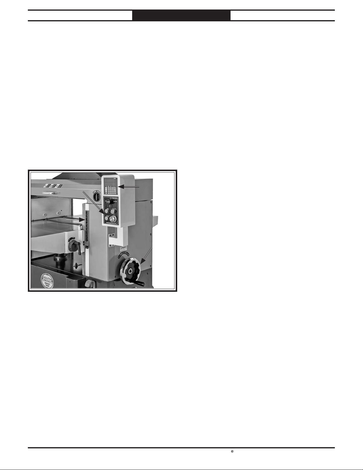
South Bend Tools
For Machines Mfd. Since 10/21 Model SB1118
OPERATION
Depth of Cut
Material Thickness Range
Minimum – Maximum Stock Thickness
The depth of cut on a planer means the amount
of material that is removed from the top of
the workpiece as it passes underneath the
cutterhead.
The depth of cut is set by adjusting the distance
of the table below the cutterhead. This distance
is the thickness of the workpiece minus the depth
of cut. The planing depth of cut is controlled
by adjusting the height of the table using the
table height handwheel, the TABLE UP/DOWN
buttons, or the digital readout (see Figure 29).
.....1⁄4"– 9"
Using Table Height Handwheel
The table height handwheel is located on the
right-hand side of the machine and can be used
to manually raise and lower the table.
Table Movement
One Full Revolution of Handwheel
To use table height w/handwheel:
1.
Push in handwheel and rotate slowly until it
engages with indented shaft located behind
it.
Rotate handwheel clockwise to raise table;
2.
rotate handwheel counterclockwise to lower
table. Stop when scale indicates desired
elevation.
Pull handwheel out to disengage it from the
3.
adjusting mechanism.
..................1⁄32"
Although the correct depth of cut varies
according to wood hardness and workpiece width,
we recommend the maximum depth of cut (per
pass) be no more than
will give better end results and put less stress
on the planer than trying to take off too much
material in a single pass.
The depth of cut can be referenced directly from
the scale on the front of the planer, as shown in
Figure 29.
1
⁄16". A series of light cuts
Note: Any time you change directions
with the handwheel, there will be a small
amount of backlash. So the first crank of
the handwheel after changing directions
will be slightly less than
long as you move the handwheel in the same
direction during operations, backlash will
not be a factor.
1
⁄32". However, as
Note: The scale functions as a general guide only,
and is not intended for low-tolerance, precision
results. To ensure accuracy, use a tape measure or
caliper to measure your workpiece thickness after
each pass.
-31-
Page 40
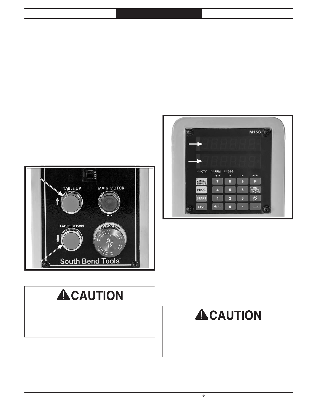
South Bend Tools
Model SB1118
OPERATION
For Machines Mfd. Since 10/21
Using TABLE UP/ DOWN Buttons
The TABLE UP/DOWN buttons are located
on the control panel and can be used to
electronically raise and lower the table. When
the digital readout is in MANUAL mode, the
movement of the table will be displayed in the
actual window of the digital readout.
To use TABLE UP/DOWN buttons:
1. Press and hold TABLE UP button (see
Figure 30) to raise table. Release button to
stop movement.
Press and hold TABLE DOWN button (see
2.
Figure 30) to lower table. Release button to
stop movement.
Using Digital Readout
The digital readout can be used to store up to ten
preset table positions, move the table to a preset
position, and add and subtract distances from a
current table position.
The digital readout features two windows (see
Figure 31). The top window shows the target
position value intended for the table (if one has
been entered), and the bottom window shows the
actual position of the table.
The handwheel should be disengaged when
using the TABLE UP/DOWN buttons or the
digital readout. Otherwise, the rapid rotation
of the handwheel could cause personal injury
or machine damage.
The digital readout has two modes of operation:
MANUAL and SINGLE.
In MANUAL mode, the table can be moved with
the TABLE UP/DOWN buttons (refer to Page
33) or the digital readout keypad.
In SINGLE mode, the digital readout provides
access to a variety of controls for making precise
table movements.
The handwheel should be disengaged when
using the TABLE UP/DOWN buttons or the
digital readout. Otherwise, the rapid rotation
of the handwheel could cause personal injury
or machine damage.
-32-
Page 41
South Bend Tools
For Machines Mfd. Since 10/21 Model SB1118
QTY
RPM
DEG
7 8 9 F
F
DEG
9 F
QTY
RPM
DEG
7 8 9 F
MANUAL
SINGLE
QTY
RPM
DEG
7 8 9 F
4 5 6
MM
INCH
MM
INCH
MANUAL
SINGLE
PROG
QTY
RPM
DEG
7 8 9 F
4 5 6
1
2 3
MM
INCH
MANUAL
SINGLE
PROG
QTY
RPM
DEG
7 8 9 F
4 5 6
1
2 3
MM
INCH
MANUAL
SINGLE
PROG
QTY
RPM
DEG
7 8 9 F
4 5 6
1
2 3
+/-
0
.
START
MM
INCH
QTY
RPM
DEG
7 8 9 F
RPM
DEG
7 8 9 F
4 5 6
1
2 3
0
.
MM
INCH
RPM
DEG
7 8 9 F
4 5 6
1
2 3
0
.
MM
INCH
MM
INCH
MANUAL
SINGLE
PROG
QTY
RPM
DEG
7 8 9 F
4 5 6
1
2 3
MM
INCH
MANUAL
SINGLE
PROG
QTY
RPM
DEG
7 8 9 F
4 5 6
1
2 3
MM
INCH
MANUAL
SINGLE
PROG
QTY
RPM
DEG
7 8 9 F
4 5 6
1
2 3
+/-
0
.
START
MM
INCH
QTY
RPM
DEG
7 8 9 F
DEG
6
MM
INCH
DEG
6
MM
INCH
MM
INCH
OPERATION
Digital Readout Buttons
Changing Digital Readout Values
The digital readout values can be expressed
either in millimeters or inches with the MM/
INCH key
MM
(see Figure 31). The light on this
INCH
key will show which measurement is active each
time the key is pressed.
Moving Table in MANUAL Mode
In MANUAL mode, the table can be moved with
the digital readout keypad.
To move table in manual mode:
MANUAL
Press MANUAL/SINGLE key
1.
MANUAL mode. Light on key will blink.
Press and hold "9" key
2.
9
release key to stop movement.
Press and hold 8 key
3.
8
down; release key to stop movement.
SINGLE
to select
to move table up;
to move table
Moving Table in SINGLE Mode
In SINGLE mode, the table can be moved to a
target position with the digital readout keypad.
Adding/Subtracting Distances
In SINGLE mode, distances can be added to or
subtracted from the current position of the table.
To add/subtract distances:
MANUAL
1. Press MANUAL/SINGLE key
select SINGLE mode. Light on key will not
illuminate.
Press +/- key
2.
+/-
. Light in target window
will blink.
— To add distance to current table position,
enter value using keypad.
— To subtract distance from current table
position, press +/- key
sign will appear on left edge of target
window. Enter value using keypad.
Press ENTER key
3.
START
will blink.
4. Press START key
. Light on START key
START
to move table to new
location.
SINGLE
to
+/-
again. A minus
To move table in SINGLE mode:
1. Press MANUAL/SINGLE key
select SINGLE mode. Light on key will not
illuminate.
Press PROGRAM key
2.
in target window.
Use keypad to enter target value for table
3.
position.
Press ENTER key
4.
START
will blink.
5. Press START key
target position.
Note: To stop table movement before table has
reached target value, press STOP key
restart, perform Steps 1–5.
MANUAL
SINGLE
to
PROG
. Light will blink
. Light on START key
START
to move table to
STOP
. To
Note: To stop table movement before table has
STOP
reached new target value, press STOP key
.
To restart, perform Steps 1–4.
Saving Preset Table Positions
Up to ten preset table positions can be stored
in permanent memory. On the keypad, these
positions are associated with the "0" through "9"
keys.
To save preset table positions:
MANUAL
1. Press MANUAL/SINGLE key
select SINGLE mode. Light on key will not
illuminate.
Press the following keys one at a time:
2.
"F" key
F
, "5" key
3. Press ENTER key
5
, "5" key
. Light in top and
bottom windows will blink, and "ProG" will
appear in target window.
SINGLE
to
5
.
-33-
Page 42
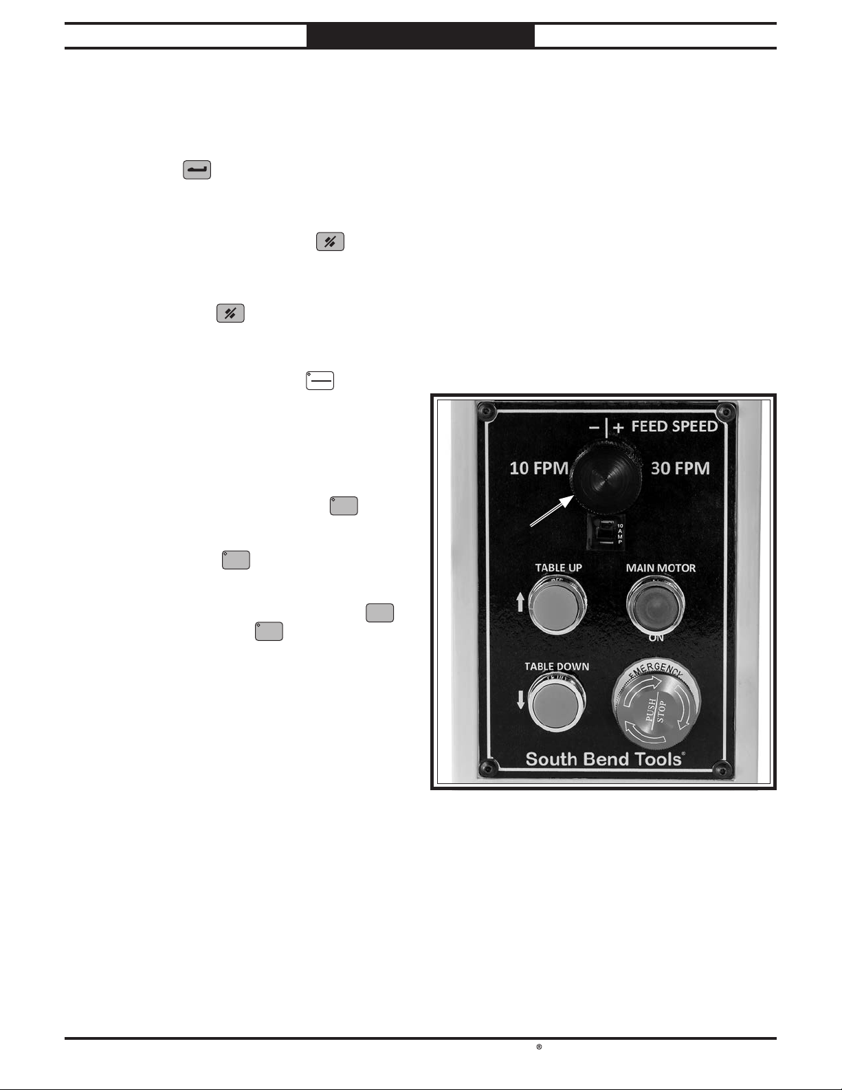
South Bend Tools
Model SB1118
QTY
RPM
DEG
7 8 9 F
MANUAL
SINGLE
PROG
QTY
RPM
DEG
7 8 9 F
4 5 6
1
2 3
MM
INCH
MANUAL
SINGLE
PROG
QTY
RPM
DEG
7 8 9 F
4 5 6
1
2 3
MM
INCH
MANUAL
SINGLE
PROG
QTY
RPM
DEG
7 8 9 F
4 5 6
1
2 3
+/-
0
.
START
MM
INCH
MANUAL
SINGLE
PROG
QTY
RPM
DEG
7 8 9 F
4 5 6
1
2 3
MM
INCH
MM
INCH
MM
INCH
MM
INCH
OPERATION
4. Press any key from "0" to "9" to store target
value. The number of key pressed will
appear to right of "ProG" in target window.
Enter table position to be saved, then press
5.
ENTER key
.
6. Repeat Steps 4–5 to save additional values.
When finished, press EXIT key
7.
.
Windows will return to normal.
Note: Cancel and exit this procedure at any time
by pressing EXIT key
.
Moving Table to Preset Position
MANUAL
1. Press MANUAL/SINGLE key
select SINGLE mode. Light on key will not
illuminate.
SINGLE
to
For Machines Mfd. Since 10/21
Feed Rate
Setting Feed Rate
Feed Rate ..............................................10–30 FPM
The infeed and outfeed rollers move the
workpiece through the planer while keeping it
flat and providing a consistent rate of movement.
The speed that these rollers move the workpiece
through the planer is the feed rate.
Generally, low feed rates are used for
dimensioning passes, while higher feed rates are
used for finishing passes.
Use the FEED SPEED control knob (see
Figure 32) to adjust the feed rate according
workpiece type and desired results.
Press key on numeric keypad that
2.
corresponds to table position value you
wish to use. This value will appear in target
window, and light on START key
START
blink.
Press START key
3.
START
to move table to
preset position.
Note: To cancel procedure, press STOP key
any time while START key
START
light is blinking.
will
STOP
-34-
Page 43
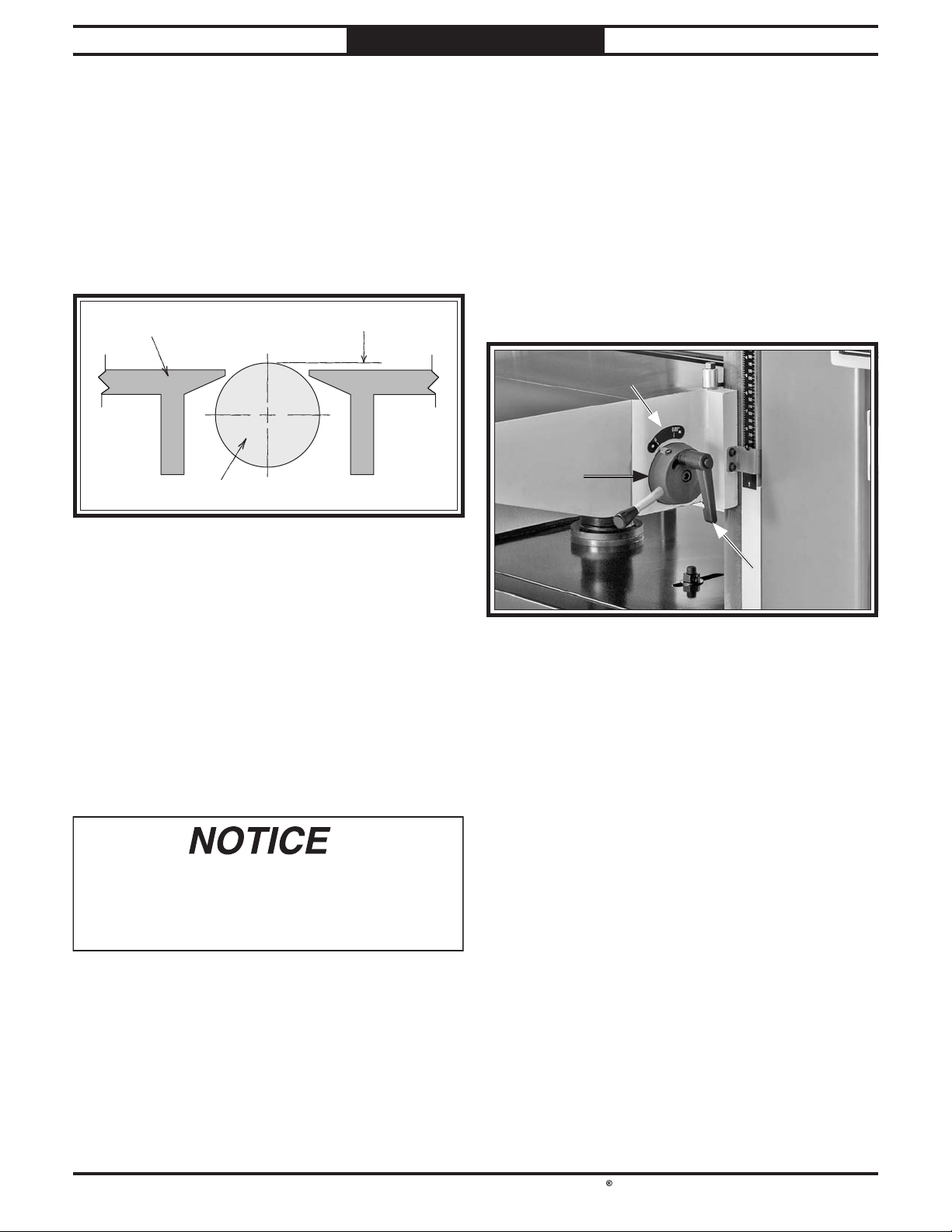
South Bend Tools
For Machines Mfd. Since 10/21 Model SB1118
The correct height of the bed rollers will vary,
depending on the type of material you intend to
plane. However, as a general rule, keep the bed
roller height range within the listed range above
the table surface, as illustrated.
When planing rough stock, set the rollers high
to keep the lumber from dragging along the bed.
When planing milled lumber, set the rollers low
to help minimize snipe.
To ensure accurate results and make the
adjustment process quicker and easier,
we recommend using a Rotacator (refer to
Accessories) to gauge the bed roller height from
the table surface. If a Rotacator is not available,
a straightedge and feeler gauges can be used, but
Bed Roller Height
OPERATION
To adjust bed roller height:
Bed Roller Height
1. DISCONNECT MACHINE FROM POWER!
2. Loosen adjustable handle on hub (see
Figure 34).
Rotate hub to desired bed roller height.
3.
Bed Roller Height Range ................. 0.002"–0.050"
Table
Roller
0.002"–0.050"
Note: This can be loosely gauged by the scale
(see Figure 34) located above the hub. For
more accurate results, use a Rotacator to
precisely determine bed roller height.
4. Tighten adjustable handle.
Bed rollers that are not adjusted to the correct
height or out of alignment with each other
can cause poor fi nishes, inconsistent planing
thickness, and other undesirable results.
-35-
Page 44
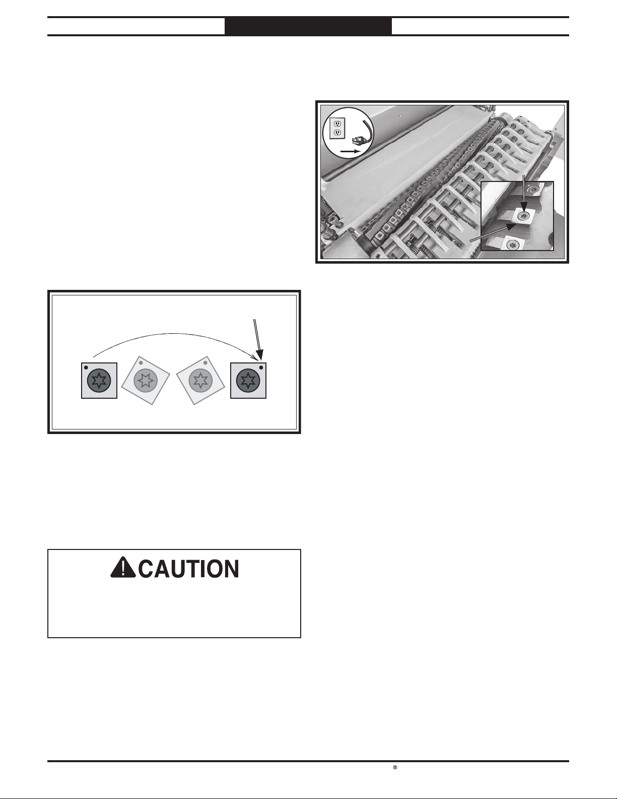
South Bend Tools
Model SB1118
The spiral cutterhead is equipped with 4-sided
indexable carbide inserts. Each insert can be
removed, rotated, and re-installed to use any one
of its four cutting edges. Therefore, if one cutting
edge becomes dull or damaged, simply rotate it
90˚ (as shown below) to use a sharp cutting edge.
The inserts have a reference dot on one corner.
The position of the reference dot on installed
inserts can be used to track which edges are
sharp/unused and which edges are dull or
damaged. Replace inserts once the reference dot
has been rotated back to its original position.
!
Cutterhead Inserts
OPERATION
Rotating/Replacing Cutterhead Inserts
For Machines Mfd. Since 10/21
Remove any sawdust or debris from head
3.
of insert, Torx screw, and surrounding area
(see Figure 36).
Reference Dot
Items Needed Qty
Hex Wrench 4mm .................................................1
T-25 Torx Bit and Driver
Carbide Cutterhead Inserts.................. As Needed
...................................................... As Needed
Rags
Light Machine Oil
The carbide inserts are very sharp and can
quickly cut your hands. ALWAYS use caution
when handling these parts to reduce the risk
of personal injury.
................................. As Needed
...................................... 1
To rotate or replace a helical cutterhead
insert:
1. DISCONNECT MACHINE FROM POWER!
2. Raise headstock cover, and remove upper
left-hand side panel.
4. Remove Torx screw and insert, then clean
all dust and debris from both parts and
cutterhead pocket.
Note: Proper cleaning of insert, Torx screw,
and cutterhead pocket is critical to achieving
a smooth finish. Dirt or dust trapped between
insert and cutterhead will raise insert,
and make marks on your workpiece when
planing.
Tip: Use low-pressure compressed air or a
vacuum nozzle to clean out cutterhead pocket.
5.
Replace insert so that a fresh cutting edge
faces outward.
— If all four insert cutting edges have been
used, replace insert with a new one.
Always position insert reference dot in
same position when installing a new
insert to aid in rotational sequencing.
Lubricate Torx screw threads with a very
6.
small amount of light machine oil, wipe
excess off, and torque screw to 48–50 inch/
pounds.
Note: If too much oil is applied to the
threads, excess oil will attempt to squeeze
out of the threaded hole and raise insert
during installation, bringing it out of height
alignment.
-36-
Page 45
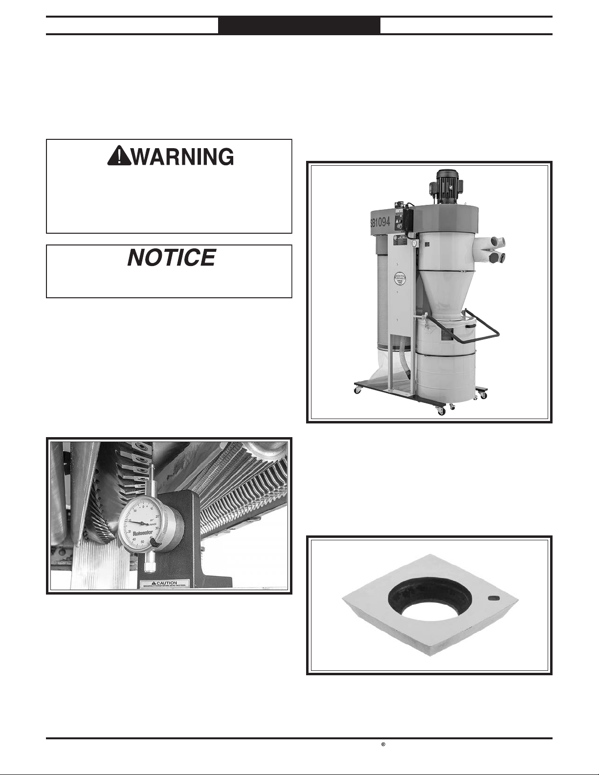
South Bend Tools
For Machines Mfd. Since 10/21 Model SB1118
order online at www.grizzly.com or call 1-800-523-4777
ACCESSORIES
Accessories
This section includes the most common
accessories available for your machine through
our exclusive dealer, Grizzly Industrial, Inc., at
grizzly.com.
Installing unapproved accessories may
cause machine to malfunction, resulting in
serious personal injury or machine damage.
To reduce this risk, only install accessories
recommended by South Bend or Grizzly.
Refer to Grizzly’s website or latest catalog for
additional recommended accessories.
ACCESSORIES
SB1094—5 HP Cyclone Dust Collector
The Model SB1094 features a 5 HP motor, a
whopping 2399 CFM of airflow capacity, and
a 72-gallon collection capacity. It's packed
with features like a built-in sound muffler, an
automatic filter paddle brush for easy cleaning, a
remote-controlled magnetic switch, and a quickrelease lift handle for easy sawdust disposal.
W1218A—Rotacator Precision Planer Tool
The Rotacator is a dial indicator on a magnetic
base, designed for quickly and accurately setting
the critical tolerances needed when making
planer adjustments. Perfect for adjusting infeed/
outfeed rollers, pressure bars, chip breakers,
and bed rollers. Also a great setup tool for other
machines! Accurate to 0.001". Indicator rotates
360°.
Figure 38. SB1094 5 HP Cyclone Dust Collector. SB1094 5 HP Cyclone Dust Collector.
H9893—Indexable Carbide Inserts, 10-Pack
These indexable carbide inserts are designed
for use in spiral or helical cutterhead systems
and made to last up to 10 times longer than a
set of HSS steel straight blades. Made of solid
carbide. Size: 15 x 15 x 2.5mm.
-37-
Page 46
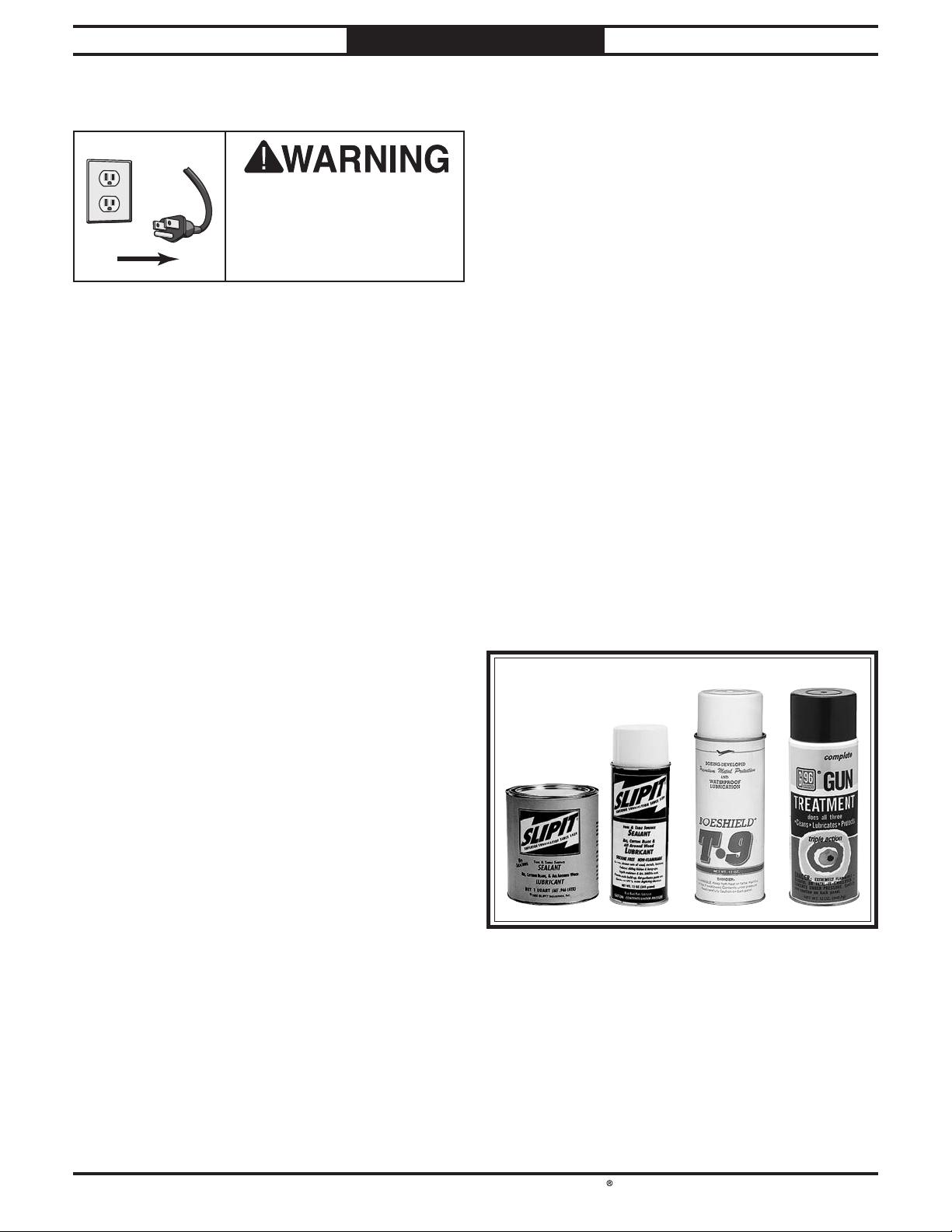
South Bend Tools
Model SB1118
!
MAINTENANCE
MAINTENANCE
For Machines Mfd. Since 10/21
Maintenance Schedule
Always disconnect
machine from power before
performing maintenance or
serious personal injury may
result.
For optimum performance from your machine,
follow this maintenance schedule and refer to
any specific instructions given in this section.
To minimize your risk of injury and maintain
proper machine operation, shut down the
machine immediately if you ever observe any
of the items below, and fix the problem before
continuing operations:
Ongoing:
• Clean machine and protect unpainted cast
iron.
• Lubricate feed roller blocks (Page 39).
• Tighten loose mounting bolts.
• Check/rotate/replace damaged or worn inserts
(Page 36).
• Check/repair/replace worn or damaged wires.
• Resolve any other unsafe condition.
Cleaning
Cleaning the Model SB1118 is relatively easy.
Vacuum excess wood chips and sawdust, and
wipe off the remaining dust with a dry cloth. If
any resin has built up, use a resin dissolving
cleaner to remove it. Treat all unpainted cast
iron and steel with a non-staining lubricant after
cleaning.
Unpainted Cast Iron
Protect the unpainted cast iron surfaces on the
table by wiping the table clean after every use—
this ensures moisture from wood dust does not
remain on bare metal surfaces. Keep tables rustfree with regular applications of products like
®
Gun Treatment, SLIPIT®, or Boeshield® T-9
G96
(see Figure 40).
G5562—SLIPIT® 1 Qt. Gel
G5563—SLIPIT® 12 Oz. Spray
G2871—Boeshield® T-9 12 Oz. Spray
G2870—Boeshield® T-9 4 Oz. Spray
H3788—G96® Gun Treatment 12 Oz. Spray
H3789—G96® Gun Treatment 4.5 Oz. Spray
Every 40 Hours of Operation:
• Clean cutterhead and inspect inserts
(Page 36).
• Lubricate table elevation leadscrews
(Page 39).
• Lubricate table ways (Page 41)
• Inspect/clean anti-kickback fingers
(Page 43).
Every 160 Hours of Operation:
• Check/tension/replace belts (Page 44).
• Clean/vacuum dust buildup from inside
cabinet and off motor.
• Lubricate table height chain and sprockets
(Page 40).
• Lubricate drive chain and sprockets
(Page 40).
Yearly:
• Change gearbox oil (Page 41).
Bare metal surfaces can quickly develop surface
rust if not coated. Machinery stored near
windows in direct sunlight or where paints,
thinners, or certain gasses are open to the air
can experience bleaching, discoloring of paint or
yellowing of clear plastic guards.
-38-
Page 47
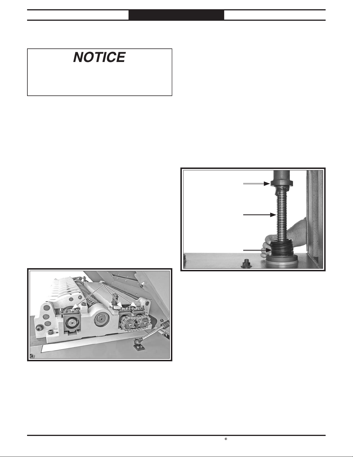
South Bend Tools
For Machines Mfd. Since 10/21 Model SB1118
MAINTENANCE
Lubrication
Failure to follow reasonable lubrication
practices as instructed in this manual for your
machine could lead to premature failure of
components and void the warranty.
Since all bearings on the Model SB1118 are
sealed and permanently lubricated, simply leave
them alone until they need to be replaced. DO
NOT lubricate them.
Follow the maintenance schedule on Page 38
and the procedures outlined below to properly
lubricate the planer components, which are
essential for long life and trouble-free operation
of your planer.
Feed Roller Blocks
Oil Type ..................SB1365 or ISO 68 Equivalent
Oil Amount
Frequency
............................................. 2–3 Drops
.................. Every 8 Hours of Operation
Table Elevation Leadscrews
Grease Type .......... T26419 or NLGI#2 Equivalent
Amount
Frequency
Items Needed Qty
Phillips Screwdriver #2 ........................................1
Open-End Wrench 19mm
The table rides on two leadscrews that are
protected by dust boots. Raise the table all the
way up, and loosen the dust boots to access the
leadscrews (see Figure 42). Use shop rags and
mineral spirits to clean away any debris and
grime, then brush a light coat of multi-purpose
grease onto the leadscrew threads. Move the
table up and down to distribute the grease.
................................................... Thin Coat
................ Every 40 Hours of Operation
.....................................1
The infeed and outfeed rollers rotate inside
bearing blocks on both ends of the rollers. Add
2–3 drops of ISO 68 machine oil to the oil cups
on each side of the head casting, as shown in
Figure 41.
-39-
Page 48
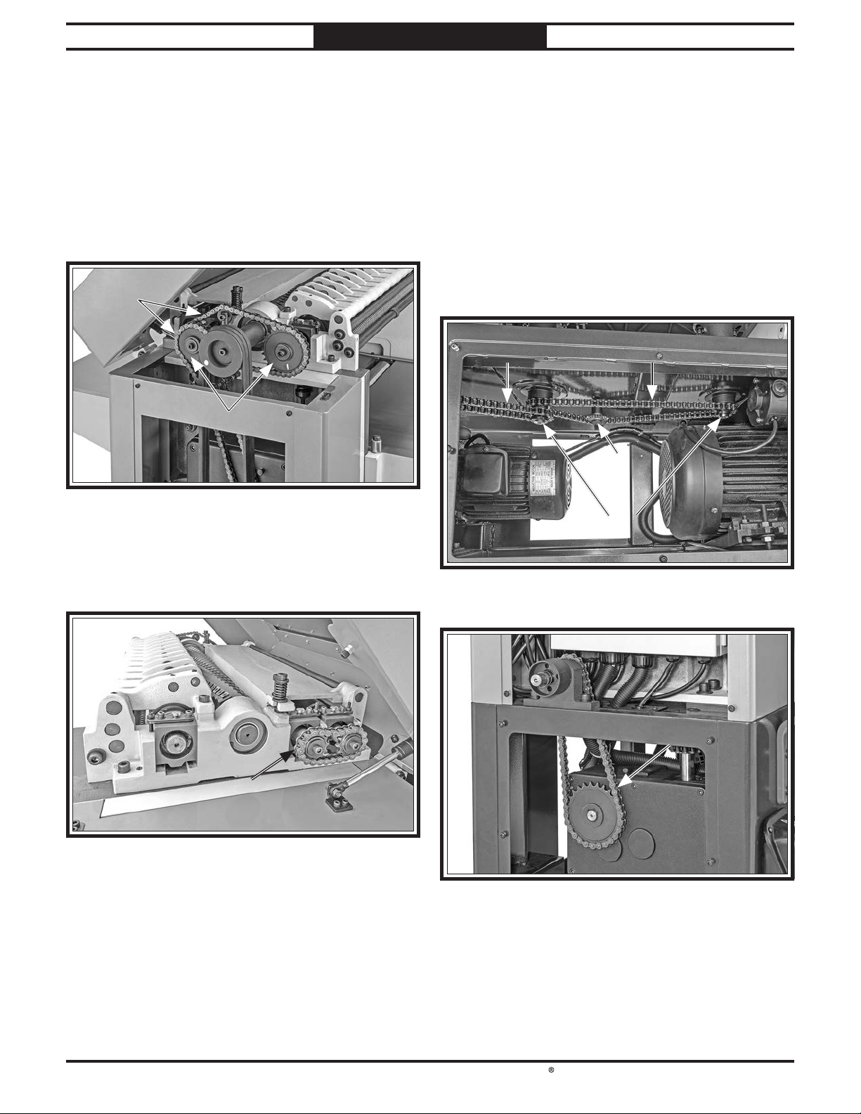
South Bend Tools
Model SB1118
Drive chain and sprockets
MAINTENANCE
For Machines Mfd. Since 10/21
Drive Chains & Sprockets
Grease Type .......... T26419 or NLGI#2 Equivalent
Amount
Frequency
The infeed and outfeed rollers receive the
transferred power from the cutterhead through
the drive chain system on the left side of the
machine, as shown in Figure 43.
................................................... Thin Coat
.............. Every 160 Hours of Operation
Table Height Chains & Sprockets
Grease Type .......... T26419 or NLGI#2 Equivalent
Amount
Frequency
The table leadscrews are adjusted by the drive
chain and synchronized by the table height chain
and sprockets located underneath the planer
base (see Figures 45–46). Use shop rags and
mineral spirits to clean away debris and grime,
then brush a light coat of multi-purpose grease
onto the chains and sprockets.
................................................... Thin Coat
.............. Every 160 Hours of Operation
On the right-hand side of the headstock, the
outfeed roller chain ensures synchronous
movement of both rollers (see Figure 44).
Use shop rags and mineral spirits to clean away
any debris and grime, then brush a light coat
of multi-purpose grease onto the chains and
sprockets.
-40-
Page 49
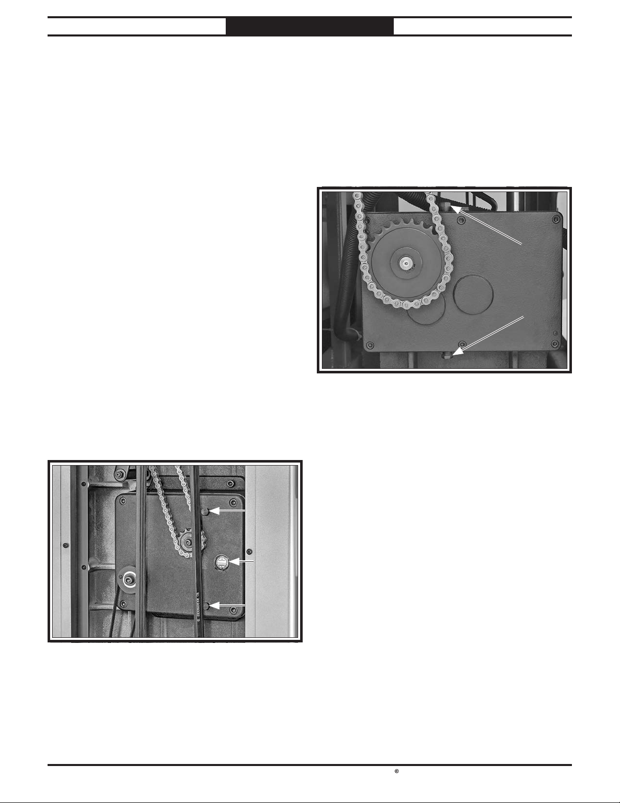
South Bend Tools
For Machines Mfd. Since 10/21 Model SB1118
MAINTENANCE
Gearbox Oil
Oil Type ................ T28088 or ISO 150 Equivalent
Oil Amount (Cutterhead/Feed Gearbox)
Oil Amount (Table Gearbox)
Frequency
Note: SAE 60W-90W gear oil may also be used.
DO NOT mix oil types!
Note: We recommend that you replace the
gearbox oil after the first 20 hours of operation.
This is a normal break-in procedure and will
help maximize the service life of the machine by
flushing away any particles from the break-in
process.
Replace gearbox oil with ISO 150 or equivalent
oil.
....... After First 20 Hours, Then Yearly
....................... 45 Oz.
..... 65 Oz.
Cutterhead/Feed Gearbox
Remove the upper access panel on the left-hand
side of the machine. Remove the oil fill plug
(see Figure 47), then remove the drain plug
and drain the old oil into a pan. Re-install the
drain plug, then refill the gearbox with ISO 150
or equivalent oil. The gearbox has the proper
amount of oil when the sight glass is filled
approximately halfway. When finished, re-install
the fill plug and the side access panel.
Table Gearbox
Remove the upper access panel on the right-hand
side of the machine. Remove the oil fill plug (see
Figure 48), then remove the drain plug and
drain the old oil into a pan. Re-install the drain
plug, then refill the gearbox with ISO 150 or
equivalent oil until it just reaches the fill plug.
When finished, re-install the fill plug and the
side access panel.
-41-
Page 50
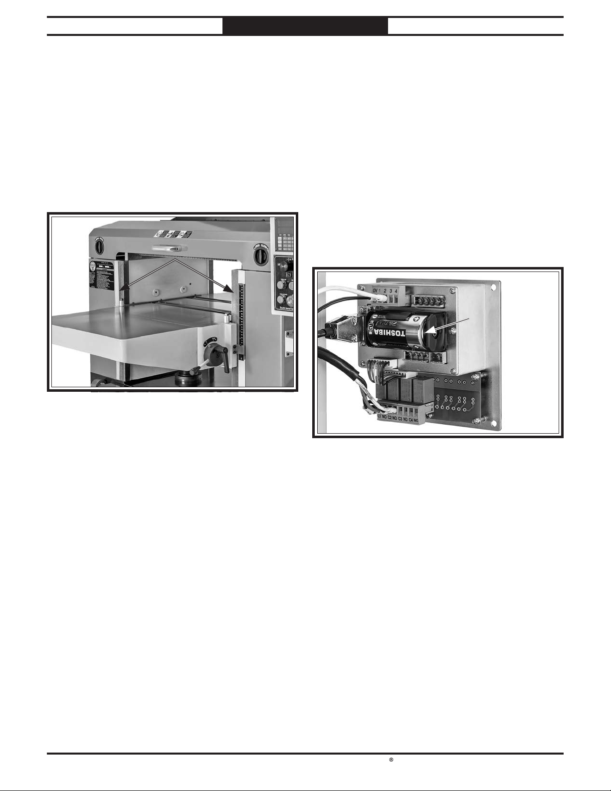
South Bend Tools
Model SB1118
MAINTENANCE
For Machines Mfd. Since 10/21
Table Ways
Oil Type ..................SB1365 or ISO 68 Equivalent
Oil Amount
Frequency
Items Needed Qty
Shop Rags .............................................. As Needed
The table slides along the ways (see Figure 49)
on the front and back of the machine. Use lightly
oiled shop rags to remove dust buildup.
............................................. Thin Coat
................ Every 40 Hours of Operation
Replacing Digital Readout Battery
If the digital readout stops operating correctly,
the D battery must be replaced.
Items Needed Qty
Hex Wrench 2.5mm ..............................................1
D Battery
To replace digital readout battery:
1.
Remove (4) button head cap screws from
............................................................... 1
digital readout faceplate, remove old battery
(see Figure 50), and install new battery.
Install digital readout faceplate and secure
2.
with screws removed in Step 1.
-42-
Page 51
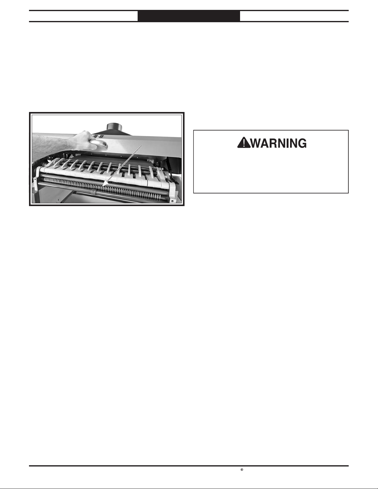
South Bend Tools
For Machines Mfd. Since 10/21 Model SB1118
Check the anti-kickback fi ngers regularly to
ensure they swing freely and easily. If the fi ngers
do not swing freely and easily, fi rst clean them
with a wood-resin solvent, then inspect them
for damage. If any of the fi ngers are damaged,
the device must be replaced before using the
machine.
Do not apply oil or other lubricants to the antikickback fi ngers that will attract dust and
restrict free movement of the fi ngers.
MAINTENANCE
Anti-Kickback Fingers
The anti-kickback fingers are an important
safety feature of your planer. The fingers hang
from a rod suspended across the head casting
and in front of the infeed roller, as shown. This
design allows the workpiece to easily enter
the planer but reduces the risk of kickback by
digging into the workpiece if it moves backward.
Proper operation of anti-kickback fi ngers is
critical for safe operation of this planer. DO
NOT operate planer if anti-kickback fi ngers are
not operating correctly. Failure to heed this
warning could result in serious personal injury.
-43-
Page 52
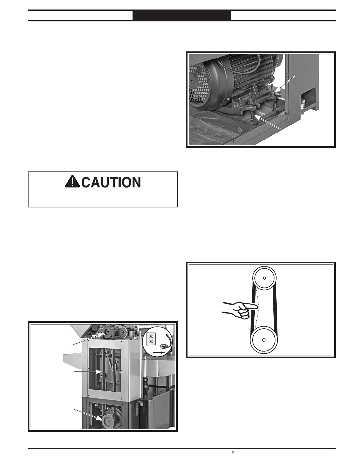
South Bend Tools
Model SB1118
!
SERVICE
Tensioning/Replacing Belts
Three V-belts transfer power from the motor
to the cutterhead, and then to the infeed and
outfeed rollers with the use of the drive chain
system. To ensure efficient transfer of power to
these systems, make sure the V-belts are always
properly tensioned and in good condition.
If the V-belts are worn, cracked, or damaged,
replace them. Always replace all V-belts at the
same time with a matched set of three, or belt
tension may not be even among the belts, causing
premature belt failure or weakened power
transfer.
Belts and pulleys will be hot after operation.
Allow them to cool before handling.
Tensioning/Replacing V-Belts
Items Needed Qty
Hex Wrench 4mm .................................................1
Open-End Wrench 19mm
Replacement V-Belts (PSB1118216)
.....................................1
.................... 3
For Machines Mfd. Since 10/21
3. Remove lower rear panel to access motor
mount hex nuts (see Figure 53).
4.
If V-belts need to be replaced, raise motor
to release belt tension, roll belts off pulleys,
then replace with a matched set of three.
To adjust V-belt tension, loosen top motor
5.
mount hex nuts (see Figure 53), then adjust
bottom hex nuts to raise or lower motor.
Note: V-belts are properly tensioned when
there is approximately
moderate pressure is applied to them midway
between pulleys, as illustrated in Figure 54.
3
⁄4" deflection when
To tension/replace V-belts:
1.
DISCONNECT MACHINE FROM POWER!
2. Open headstock cover and remove upper
and lower side panels on left-hand side of
machine (see Figure 52).
Cutterhead
Approximately
3
⁄4" Deflection
After V-belts are properly tensioned, tighten
6.
top motor mount hex nuts, then install lower
rear panel and upper and lower side panels,
and close headstock cover.
Pulley
Motor
Pulley
-44-
Page 53
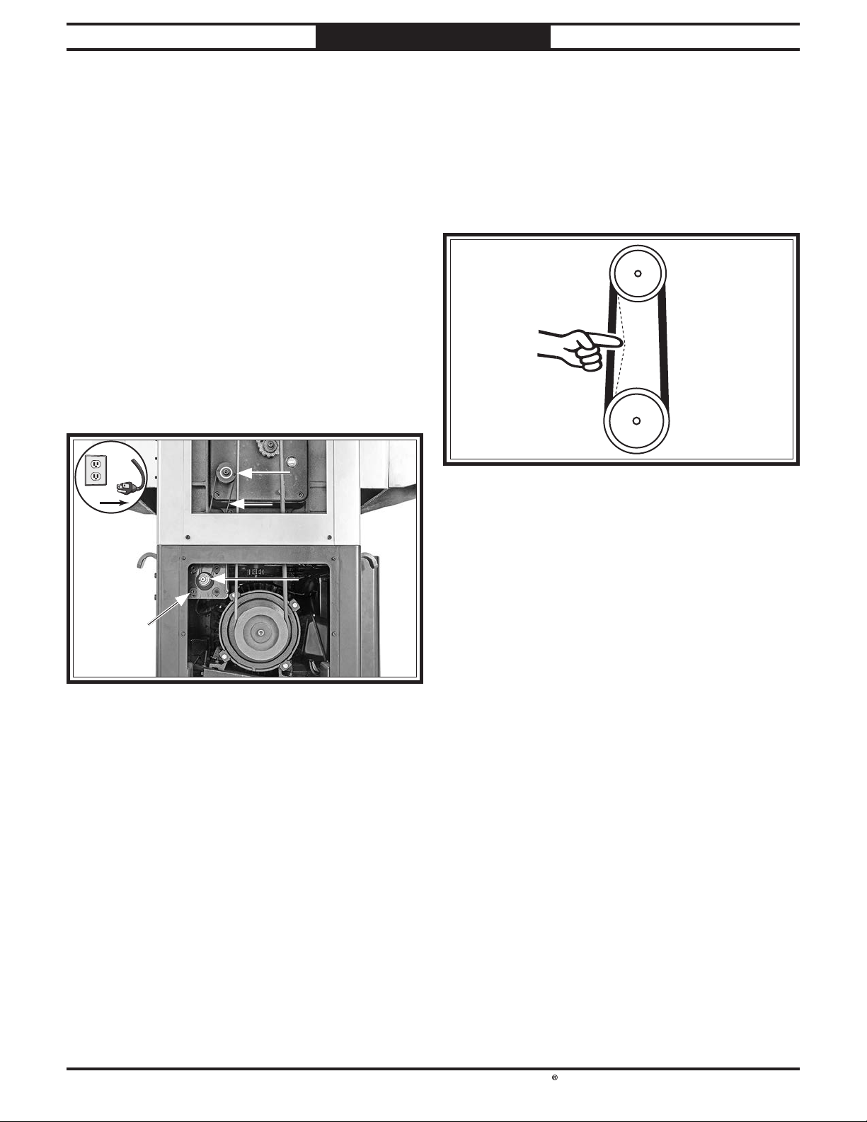
South Bend Tools
For Machines Mfd. Since 10/21 Model SB1118
!
Tensioning/Replacing Timing Belt
Items Needed Qty
Hex Wrenches 4, 5mm .................................... 1 Ea
SERVICE
To adjust timing belt tension, gently press on
5.
feed motor output shaft (see Figure 55), and
tighten cap screws when tension is correct.
To tension/replace timing belt:
1. DISCONNECT MACHINE FROM POWER!
2. Open headstock cover and remove upper
and lower side panels on left-hand side of
machine (see Figure 55).
Loosen (4) cap screws (see Figure 55)
3.
securing feed motor to mounting plate.
If timing belt needs to be replaced, gently lift
4.
feed motor output shaft (see Figure 55) to
release belt tension, roll belt off pulleys, then
replace with new belt.
Note: Timing belt is properly tensioned when
there is approximately
moderate pressure is applied to them midway
between pulleys, as illustrated in Figure 56.
Approximately
1
⁄4" Deflection
1
⁄4" deflection when
Gearbox
Pulley
Motor
Pulley
-45-
Page 54
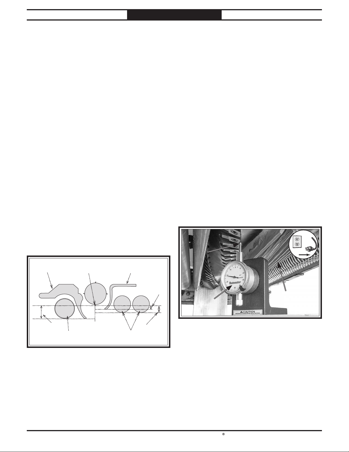
South Bend Tools
Model SB1118
!
SERVICE
For Machines Mfd. Since 10/21
Setting Feed Rollers, Chip Breaker & Pressure Bar Heights
It is essential that the feed rollers, chip breaker,
and pressure bar are set at the correct distance
below the cutterhead inserts at BDC (bottom
dead center) to ensure that the workpiece moves
through the planer evenly and the correct
distance from the cutterhead inserts.
To ensure accurate results and make the
adjustment process quicker and easier, we
recommend using a Rotacator for these
adjustments (refer to Page 37).
If a Rotacator is not available, a 6' 2x4 cut into
two even-sized pieces and a feeler gauge set can
be used, but care must be taken when jointing
the wood to achieve accurate results and ensure
both boards are the exact same height.
Dist. Below Cutterhead Insert at BDC (Figure 57)
Infeed Roller ...........................................0.020"
A.
Chip Breaker ..........................................0.020"
B.
Pressure Bar .............................................0.00"
C.
Outfeed Roller ........................................0.020"
D.
Using a Rotacator
Items Needed Qty
Hex Wrench 3mm .................................................1
Open-End Wrench 10mm
Metal Shims
Rotacator (see Page 37)
.......................................... As Needed
To use a Rotacator to check/adjust heights:
1. DISCONNECT MACHINE FROM POWER!
2. Make sure all inserts are properly installed
(refer to Rotating/Replacing Cutterhead
Inserts on Page 36) and table is parallel
to cutterhead (refer to Adjusting Table
Parallelism on Page 52).
Lower table at least 4" below headstock
3.
casting using handwheel.
Raise headstock cover.
4.
5. Using Rotacator, find bottom dead center
(BDC) of any insert edge by slowly rocking
cutterhead pulley back and forth, then set
Rotacator dial to "0" (see Figure 58).
.....................................1
.......................................1
Chip
Breaker
A & B
BDC
(Bottom Dead Center)
Infeed
Roller
Pressure
Bar
Outfeed
Rollers
C
D
6. Keeping Rotacator dial at "0", position it
under right-hand side of infeed roller and
find BDC of a serrated edge by rocking
infeed roller back and forth.
-46-
Page 55
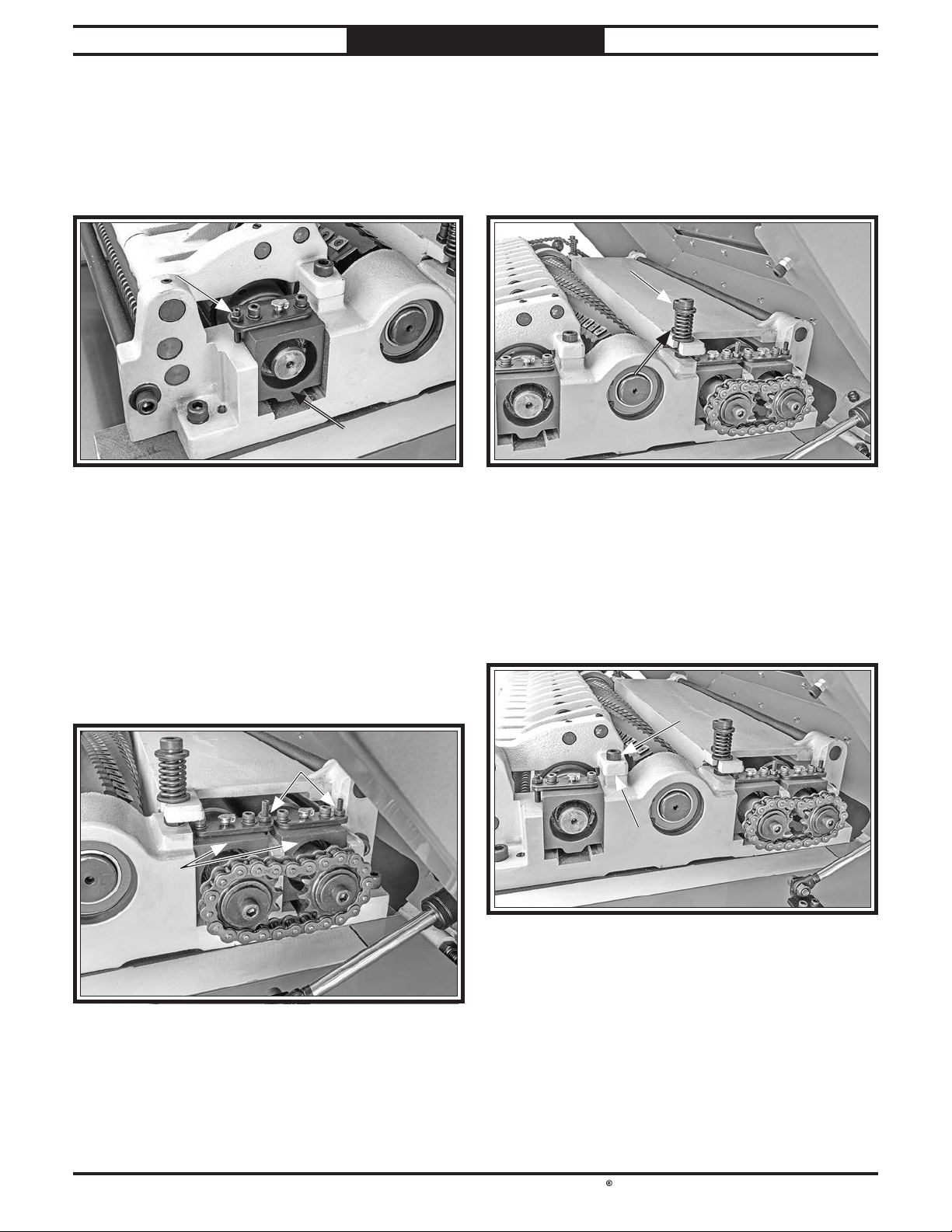
South Bend Tools
For Machines Mfd. Since 10/21 Model SB1118
SERVICE
7. Loosen jam nuts and use set screws (see
Figure 59) on each side of infeed roller to
adjust height of infeed roller bushing block
until Rotacator dial shows 0.020", which is
the recommended distance for infeed roller
below the cutterhead.
Check both sides of infeed roller and, if
8.
necessary, make further adjustments until
infeed roller height from side to side is 0.020"
below BDC of cutterhead insert, then tighten
both jam nuts.
Keeping same "0" reference on Rotacator dial
9.
from Step 5, repeat Steps 7–8 for outfeed
rollers (see Figure 60).
10.
Using same "0" reference on Rotacator
dial from Step 5, perform similar steps
as described previously to adjust height
of pressure bar (see Figure 61) to its
recommended specification given at
beginning of this subsection.
Repeat Step 10 for chip breaker height
11.
adjustment using controls shown in Figure
62. If necessary to achieve correct height
adjustment, remove both caps screws and
insert metal shims between chip breaker and
headstock casting, then re-install cap screws.
Lower headstock cover.
12.
-47-
Page 56
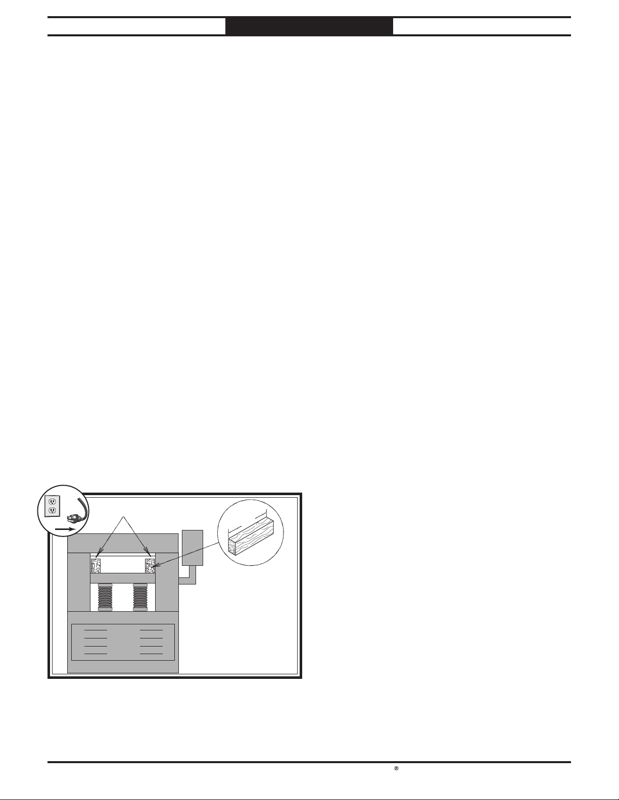
South Bend Tools
Model SB1118
!
SERVICE
For Machines Mfd. Since 10/21
Using Wood Blocks
Items Needed Qty
Hex Wrench 3mm .................................................1
Open-End Wrench 10mm
2x4 6' Long
Feeler Gauge Set
Metal Shims
.............................................................1
................................................... 1
..........................................................1
To use wood blocks to check/adjust heights:
1. Build wood blocks by cutting a straight
6-foot-long 2x4 in half.
Note: Having the wood blocks at an even
height is critical to the accuracy of your
overall adjustments. For best results, make
the 2x4 square with a jointer and table saw
before cutting it in half.
Make sure all inserts are properly installed
2.
(refer to Rotating/Replacing Cutterhead
Inserts on Page 36 for detailed
instructions).
DISCONNECT MACHINE FROM POWER!
3.
4. Lower table at least 4" below head casting.
5. Lower bed rollers below table surface (refer
to Bed Roller Height on Page 35).
Place wood blocks along sides of table, as
6.
illustrated in Figure 63.
.....................................1
7. Raise the headstock cover.
8. Use handwheel to adjust table height until
there is a 0.020" gap between edge of a
carbide insert at BDC and wood blocks, as
measured with a feeler gauge.
Note: The wood blocks will now hold infeed
and outfeed rollers, chip breaker, and
pressure bar at same level as insert at BDC.
Loosen infeed roller jam nuts (see Figure 59
9.
on Page 47) and turn set screw on each end
of the infeed roller to raise it above the wood
blocks.
. Turn set screws back down so infeed roller
10
just touches wood blocks on both sides.
Tighten jam nuts, making sure set screws do
11.
not move.
Without moving table, adjust outfeed rollers,
12.
pressure bar, and chip breaker (Figures 60–
62 on Page 47) in the same manner, using
wood blocks as reference point.
Note: The pressure bar should be at the same
height as the cutterhead. You will need the
feeler gauge with the wood blocks to ensure
that it is at the same height as the cutterhead
with the carbide insert at BDC.
Wood Blocks
-48-
36"
Page 57
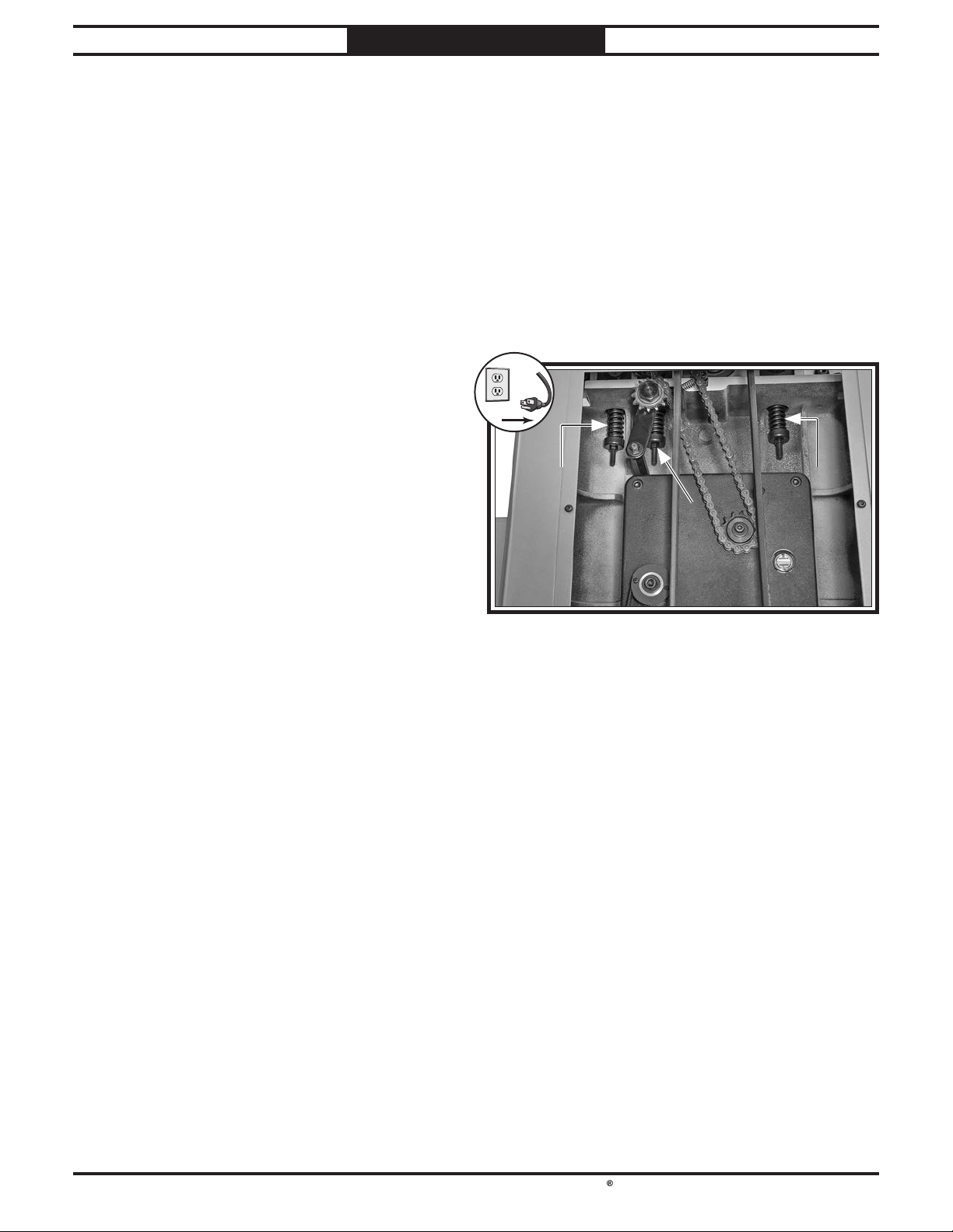
South Bend Tools
For Machines Mfd. Since 10/21 Model SB1118
!
Adjusting Feed Roller
SERVICE
Tools Needed Qty
Hex Wrench 4mm .................................................1
Open-End Wrench 14mm
.....................................1
Spring Tension
The infeed and outfeed rollers keep the
workpiece moving through the planer. Springs
exert downward pressure on the feed rollers
while allowing them to raise with an uneven
workpiece surface. Proper spring tension is
crucial to keep the workpiece moving through the
planer during operation without pulling from one
side to the other.
The amount of tension on the infeed roller needs
to be enough to push the workpiece into the
cutterhead but not enough to gouge or bind the
workpiece.
The amount of tension on the outfeed rollers
needs to be enough to pull the workpiece along
the planing path without binding and prevent
snipe at the end of the workpiece. The ideal feedroller spring tension varies depending upon the
type of wood you plane. When adjusting spring
tension, keep the following in mind:
To adjust feed roller spring tension:
1.
DISCONNECT MACHINE FROM POWER!
2. Raise headstock cover and remove upper side
panels on both sides of machine.
Tighten hex nut at base of tension spring
3.
(see Figure 64) to increase tension; loosen
hex nut to decrease tension.
• If you are planing milled lumber with a
consistent surface, use less spring tension to
reduce the risk of marring the workpiece.
• If you are planing rough lumber with
inconsistent surfaces, use greater spring
tension to keep the stock moving through the
planer.
• If the workpiece consistently stops feeding
during operation, the spring tension may
need to be increased.
4. When finished, re-installed side panels and
close headstock cover.
-49-
Page 58
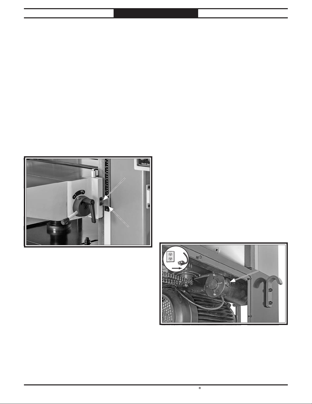
South Bend Tools
Model SB1118
!
!
SERVICE
For Machines Mfd. Since 10/21
Calibrating Table Height Indicator
The indicator on the depth scale should match
the value shown in the bottom window of the
digital readout.
Items Needed Qty
Hex Wrench 4mm .................................................1
To calibrate table height scale:
1. Raise table all the way up.
2. Loosen (2) cap screws shown in Figure 65.
Adjust scale pointer to 1⁄4" mark on scale,
3.
then tighten cap screws (see Figure 65).
Replacing Feed Motor Brushes
This planer is equipped with a universal motor
that uses two carbon brushes to transmit
electrical current inside the motor. These
brushes are considered to be regular "wear
items" or "consumables" that will need to be
replaced during the life of the motor. The
frequency of required replacement is often
related to how much the motor is used and how
hard it is pushed.
Replace the carbon brushes at the same time
when the motor no longer reaches full power,
or when the brushes measure less than
(new brushes are
Items Needed Qty
Hex Wrench 4mm .................................................1
Flat Head Screwdriver
Motor Brushes (SB1118380-3)
5
⁄8" long).
..........................................1
...................... 1 Set
1
⁄4" long
Figure 65. Location of adjustment screws for table
height scale.
To replace feed motor brushes:
1. DISCONNECT MACHINE FROM POWER!
2. Remove rear access panel.
3. Remove brush caps and worn brushes, (see
Figure 66).
-50-
4.
Replace both motor brushes, then install
brush caps.
Install rear access panel.
5.
Page 59
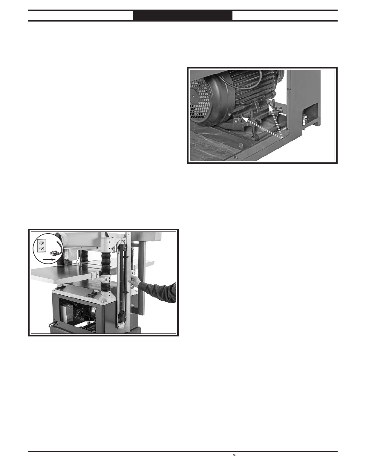
South Bend Tools
For Machines Mfd. Since 10/21 Model SB1118
!
pulley alignment
Checking Pulley Alignment
Proper pulley alignment prevents premature
V-belt wear and proper power transfer from the
motor. The pulleys are properly aligned when
they are parallel and in the same plane as each
other.
Items Needed Qty
Straightedge 48" ....................................................1
Open-End Wrenches 14, 17mm
Hex Wrench 4mm
To check/re-align pulleys:
1. DISCONNECT MACHINE FROM POWER!
.................................................1
...................... 1 Ea
SERVICE
4.
Loosen (4) hex nuts that secure motor to
mounting plate (see Figure 68), shift motor
until pulleys are aligned, then tighten hex
nuts.
2. Raise headstock cover, and remove upper
and lower access panels on left side of
machine.
3.
Use straightedge to check pulley alignment
(see Figure 67).
5.
Check pulley alignment, and repeat Step
3 as necessary until you are satisfied with
results.
6.
Tighten all fasteners, then check V-belt
tension (refer to Tensioning/Replacing
V-belts on Page 44).
7.
Install rear and side access panels, and close
headstock cover.
— If pulleys are parallel and in the same
plane, no adjustment is necessary.
— If pulleys are not parallel or in the same
plane, remove rear access panel, then
proceed to Step 4.
-51-
Page 60
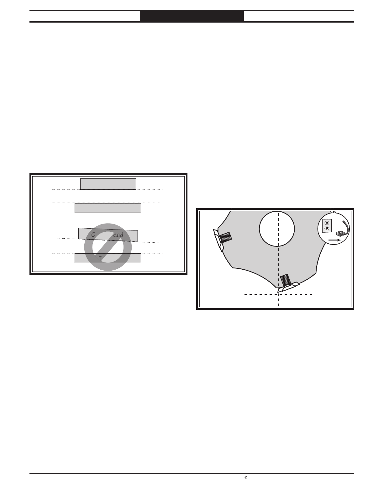
South Bend Tools
Model SB1118
Center
!
SERVICE
For Machines Mfd. Since 10/21
Adjusting Table Parallelism
Maximum Allowable Tolerances
Cutterhead/Table Side-to-Side
Tools Needed Qty
Rotacator ...............................................................1
Hex Wrenches 6, 10mm
Table parallelism is critical to the operation of
the machine. As such, it is essential that the
table is adjusted parallel with the cutterhead
(within 0.002") from side-to-side, as illustrated in
Figure 69.
Parallel Parallel
SIDE-TO-SIDE
.................................. 1 Ea
Cutterhead
Table
Cutterhead
.....................0.003"
FRONT
VIEW
Table Parallelism Adjustments
The table is adjusted by turning the elevation
leadscrew housing brackets underneath the
table.
To adjust table parallelism:
1. DISCONNECT MACHINE FROM POWER!
2. Make sure all inserts are properly installed
(refer to Rotating/Replacing Cutterhead
Inserts on Page 36).
Lower table at least 4" below headstock
3.
casting using handwheel.
Raise headstock cover.
4.
5. On left-hand edge of cutterhead, find bottom
dead center (BDC) of any carbide insert (see
Figure 70).
Not Parallel Not Parallel
Table
Table Parallelism Inspection
The easiest way to determine if your head
casting has a parallelism problem is to plane a
workpiece and measure the thickness in multiple
locations. If the workpiece is tapered from left-toright or from front-to-back, then parallelism may
be a problem.
Use your Rotacator (refer to Page 37) to further
inspect the table parallelism. If you do not have
a Rotacator, a wood block and feeler gauges may
be used, but extra care must be taken to ensure
accuracy. If the table is not within the maximum
allowable tolerances, it must be adjusted.
Bottom Dead
Center
— If using a Rotacator, find BDC of carbide
insert by slowly rocking cutterhead pulley
back and forth, and set Rotacator dial to
.
"0"
— If a Rotacator is not available, use a
wood block and a feeler gauge. Slowly
rock cutterhead pulley back and forth so
carbide insert just makes contact as it
passes feeler gauge.
-52-
Page 61
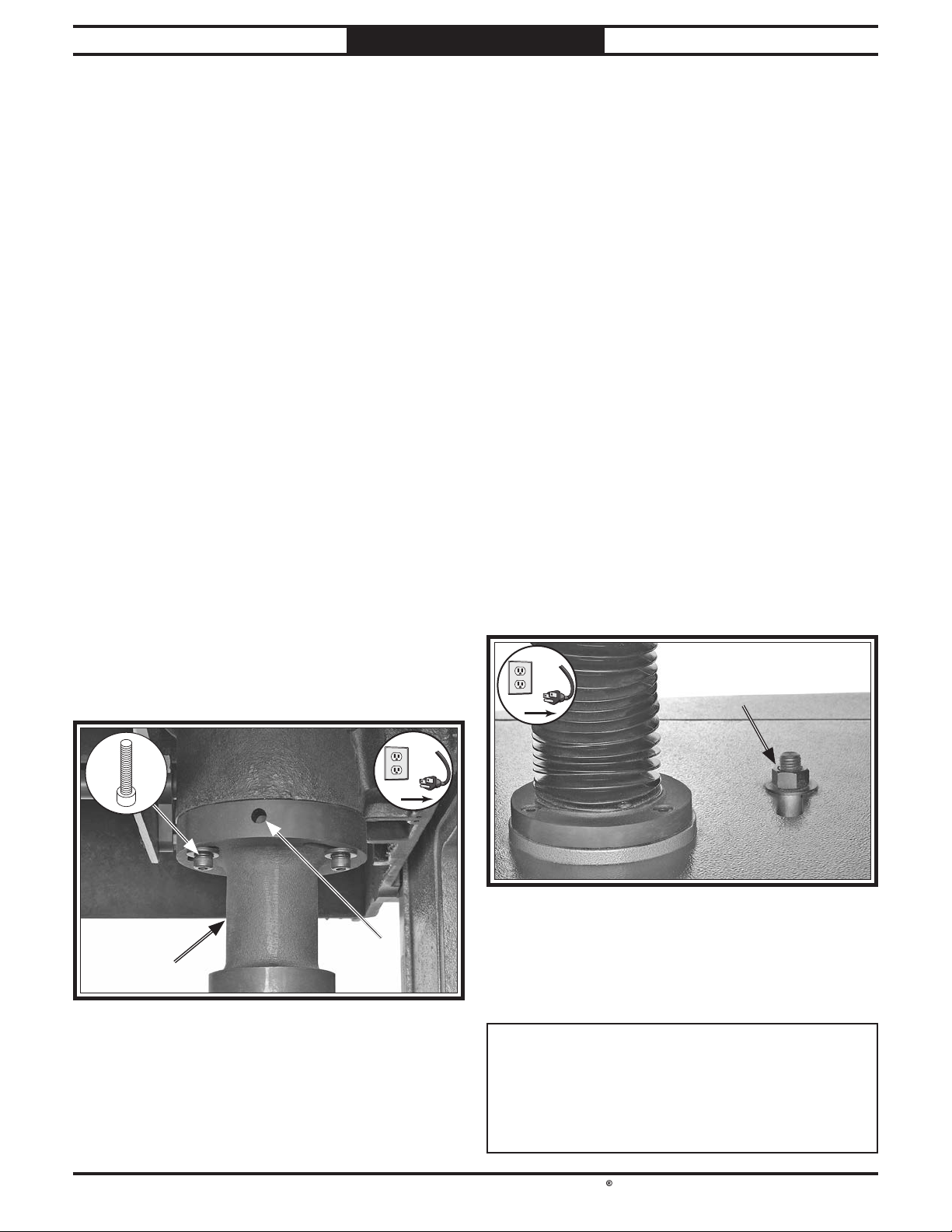
South Bend Tools
For Machines Mfd. Since 10/21 Model SB1118
!
!
6. Keeping Rotacator dial at "0", position it
under right-hand edge of cutterhead and find
bottom dead center (BDC).
SERVICE
Tensioning Table Height Chain
— If value of measurement on right-hand
side of table differs less than 0.003" from
left-hand side, then parallelism is within
tolerance and no adjustment is necessary.
— If value of measurement on right-hand
side of table differs more than 0.003" from
left-hand side, then parallelism is out of
tolerance and must be adjusted. Proceed
to Step 7.
Determine which side of table to adjust to
7.
bring table parallel with the cutterhead to
within 0.003".
The table height chain is located beneath the
table, and it transfers movement from the table
gearbox to the leadscrews that control table
height. The chain can be adjusted to remove
slack if the chain stretches over time or is
loosened during table leveling procedures.
Tools Needed Qty
Hex Wrench 4mm .................................................1
Wrench or Socket 24mm
To tension table height chain:
1. DISCONNECT MACHINE FROM POWER!
....................................... 1
On that side of table, loosen (2) cap
8.
screws on leadscrew housing bracket (see
Figure 71).
Insert long end of 10mm hex wrench
9.
into leverage hole (see Figure 71), and
turn bracket until table is parallel with
cutterhead from side to side.
Note: The slight deformation of the rubber
elevation screw cover is normal and will not
affect table movement.
x 2
2. Remove rear access panel.
3. Loosen idler assembly hex nut (see Figure
72), push idler sprocket (see Figure 45
on Page 40) against chain with moderate
pressure to eliminate slack, then tighten
hex nut while maintaining pressure on idler
assembly.
10.
Tighten cap screws loosened in Step 8.
4. Clean and lubricate chain and sprockets
(refer to Table Height Chain & Sprockets
on Page 40 for detailed instructions), then
re-install rear access panel.
NOTICE
DO NOT let chain fall off sprockets. It can
be very difficult to return chain to its proper
location on sprockets without changing table
adjustments.
-53-
Page 62
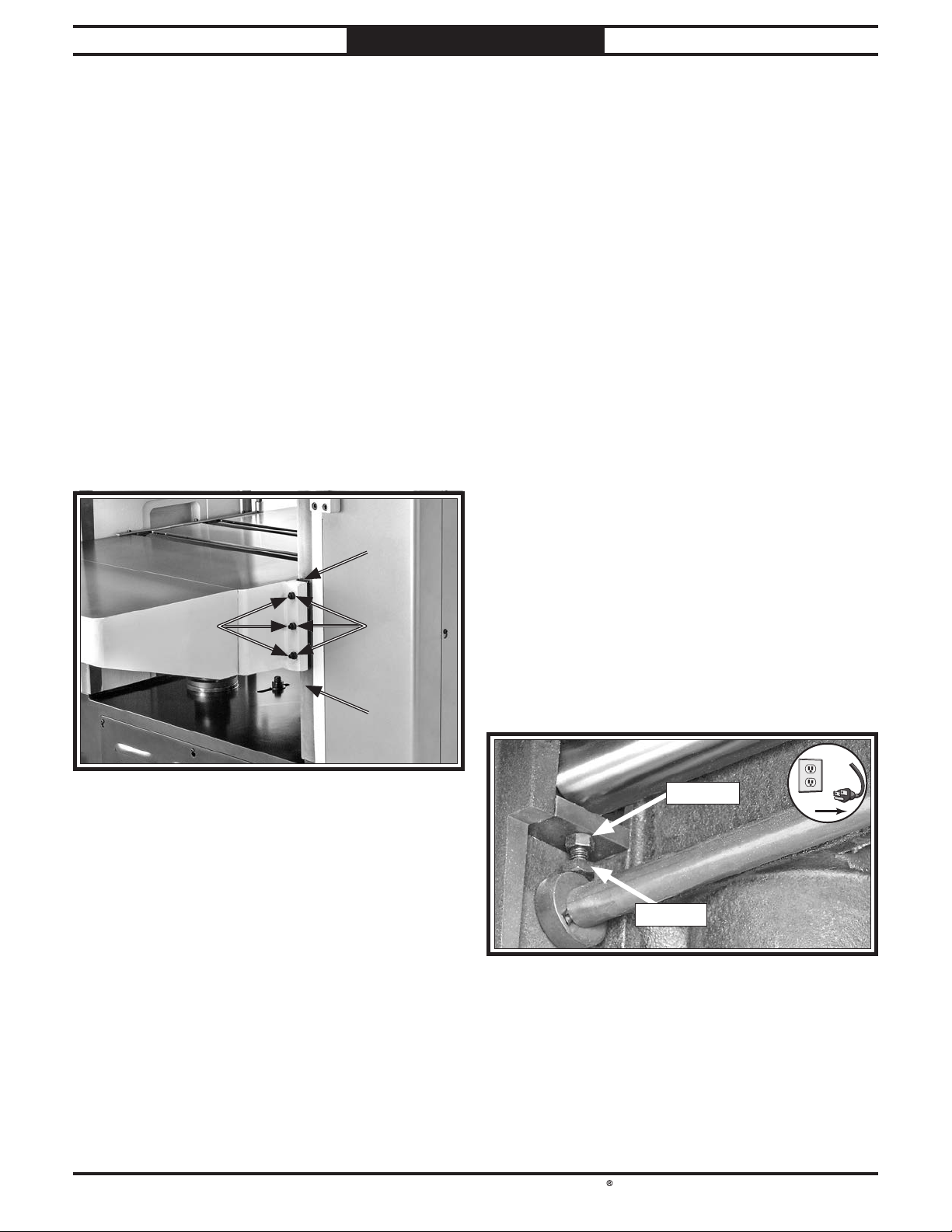
South Bend Tools
Model SB1118
!
SERVICE
For Machines Mfd. Since 10/21
Adjusting Table Gibs
The function of the table gibs is to eliminate
excessive play in the table movement. Tight gibs
make table movement more accurate but stiff.
Loose gibs make moving the table sloppy but
easier. The goal of gib adjustment is to remove
unnecessary sloppiness without causing the ways
to bind.
Tools Needed Qty
Hex Wrench 4mm .................................................1
Open-End Wrench or Socket 13mm
To adjust table gibs:
1. DISCONNECT MACHINE FROM POWER!
2. Loosen jam nuts on gib set screws (see
Figure 73) on both sides of table.
..................... 1
Calibrating Bed Rollers
The bed rollers provide even planing pressure
from side to side and front to back by pushing the
workpiece up against the feed rollers. The height
of the table rollers can be adjusted according to
the type of material being planed.
Tools Needed Qty
Open-End Wrenches 14, 17mm ...................... 1 Ea
Straightedge 36"
To calibrate table roller scale:
1. DISCONNECT MACHINE FROM POWER!
2. Rotate bed roller hub to "0" setting.
3. Place straightedge across bed rollers on
left side of table. Rollers should just touch
straightedge.
— If rollers do just touch straightedge, they
are level with table. Proceed to Step 5.
....................................................1
Evenly tighten gib set screws a small
3.
amount, then check table by moving it up
and down with handwheel. Adjust set screws
as needed until friction of table movement is
balanced between minimal play and ease of
movement.
4.
When satisfied with results, tighten jam nuts
on all set screws, being careful not to let the
set screws move.
— If rollers do not just touch straightedge,
they are not level with table. Proceed to
Step 4.
Loosen jam nut (see Figure 74), adjust hex
4.
bolt so roller just touches straightedge, then
tighten jam nut.
Repeat Steps 3-4 on right side of table.
5.
-54-
Note: Repeat adjustments side to side until
roller height is correct.
Repeat Steps 1-5 on second roller.
6.
Page 63
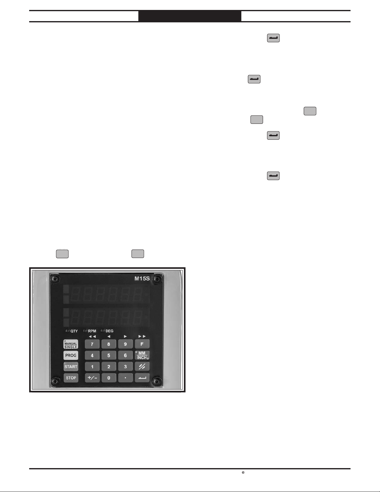
South Bend Tools
For Machines Mfd. Since 10/21 Model SB1118
DEG
3
MM
INCH
MM
INCH
DEG
2 3
.
MM
INCH
MM
INCH
MM
INCH
MM
INCH
SERVICE
Calibrating digital readout
Calibrating Digital
Press ENTER key
5.
target window will blink, and "OriGin" will
. A light in (top)
appear.
Readout
The value shown in the actual (bottom) window
of the digital readout should be precisely equal to
the actual distance from the table to BDC of the
cutterhead inserts.
Tool(s) Needed Qty
Calipers .............................................................1 Pr
6. Enter value recorded in Step 3, then press
ENTER key
to save actual table position
value in digital readout memory.
To load actual table position value for
7.
operational use, press "F" key
press "0" key
0
.
F
, then
To calibrate digital readout:
1.
Ensure table is parallel with cutterhead
(refer to Adjusting Table Parallelism on
Page 52).
Plane a wide piece of stock, making sure that
2.
top and bottom of workpiece are as parallel
as possible.
Use calipers to measure workpiece thickness
3.
in multiple places, and record average value
of these measurements.
On digital readout (see Figure 75) press "F"
4.
key
F
, then press "2" key
2
.
8. Press ENTER key
. A light will blink in
both windows, then "CHAnGE" will appear
in top window, and "OrG??" will appear in
bottom window.
Press ENTER key
9.
again to load and use
stored value for actual distance from table to
cutterhead insert.
-55-
Page 64
South Bend Tools
Model SB1118
TROUBLESHOOTING
TROUBLESHOOTING
For Machines Mfd. Since 10/21
If you need replacement parts, or if you are unsure how to do any of the solutions given here, feel free
to call us at (360) 734-1540.
Symptom Possible Cause Possible Solution
Machine does not
start or power
supply breaker
immediately trips
after startup.
1.
EMERGENCY STOP button
depressed/at fault.
2.
Machine circuit breaker tripped or
at fault.
3.
Blown fuse.
4.
Incorrect power supply voltage or
circuit size.
5.
Motor speed potentiometer at fault.
6.
Power supply circuit breaker
tripped or fuse blown.
7.
Motor wires connected incorrectly.
8.
Thermal overload relay has tripped/
at fault.
9.
Contactor not energized/at fault.
10.
Wiring broken, disconnected, or
corroded.
11.
Motor brushes worn out.
12.
MAIN MOTOR button or circuit
breaker switch at fault.
13.
Circuit board at fault.
14.
Headstock cover safety switch
engaged/at fault.
15.
Motor or motor bearings at fault.
1.
Rotate EMERGENCY STOP button head to reset.
Replace if at fault.
2.
Reset circuit breaker on switch.
3.
Replace fuse/ensure no shorts.
4.
Ensure correct power supply voltage and circuit
size.
5.
Test/replace if at fault.
6.
Ensure circuit is free of shorts. Reset circuit breaker
or replace fuse.
7.
Correct motor wiring connections.
8.
Reset. Adjust or replace if at fault.
9.
Test all legs for power; replace if necessary.
10.
Fix broken wires or disconnected/corroded
connections.
11.
Remove/replace brushes (Page 50).
12.
Replace switch/circuit breaker.
13.
Inspect/replace if at fault.
14.
Close headstock cover; replace switch.
15.
Replace motor.
Feed motor does
not start or stalls.
Machine stalls or is
underpowered.
1.
Motor brushes worn out.
1.
Workpiece material unsuitable for
machine.
2.
Feed rate/cutting speed too fast.
3.
Machine undersized for task.
4.
Circuit board at fault.
5.
Motor speed potentiometer at fault.
6.
Belt(s) slipping/pulleys misaligned.
7.
Feed motor wired incorrectly.
8.
Feed motor brushes worn out.
9.
Pulley/sprocket slipping on shaft.
10.
Motor overheated, tripping machine
circuit breaker.
11.
Contactor not energized/at fault.
12.
Feed motor or motor bearings at
fault.
1.
Replace motor brushes (Page 50).
1.
Only cut wood/ensure moisture is below 20% (Page
28).
2.
Decrease feed rate/cutting speed.
3.
Use correct blade/reduce feed rate or depth of cut.
4.
Inspect and replace if at fault.
5.
Test and replace if at fault.
6.
Clean/tension/replace belt(s) (Page 44); ensure
pulleys are aligned (Page 51).
7.
Wire motor correctly.
8.
Replace motor brushes (Page 50).
9.
Tighten/replace loose pulley/shaft.
10.
Clean motor, let cool, and reduce workload. Reset
breaker.
11.
Test all legs for power; repair/replace if at fault.
12.
Replace motor.
-56-
Page 65

South Bend Tools
For Machines Mfd. Since 10/21 Model SB1118
TROUBLESHOOTING
Symptom Possible Cause Possible Solution
Table moves up
when it should
move down.
Table will not
move.
Machine has
vibration or noisy
operation.
1.
Power connections wired out of
phase.
1.
Limit switch engaged/at fault.
2.
Blown fuse.
3.
Thermal overload relay has tripped/
at fault.
4.
Contactor not energized/at fault.
5.
Table motor at fault.
1.
Motor or component loose.
2.
Feet not adjusted properly.
3.
V-belt(s) worn, loose, pulleys
misaligned or belt slapping cover.
4.
Pulley loose.
5.
Motor mount loose/broken.
6.
Motor fan rubbing on fan cover.
7.
Bed rollers protruding unevenly.
8.
Cutterhead bearings at fault.
9.
Motor bearings at fault.
1.
Correct phase polarity (Page 24).
1.
Inspect/replace if at fault.
2.
Replace fuse/ensure no shorts.
3.
Reset. Adjust or replace if at fault.
4.
Test all legs for power (A1, A2); repair/replace if at
fault.
5.
Inspect/replace if at fault.
1.
Replace damaged or missing bolts/nuts or tighten if
loose.
2.
Adjust machine feet to stabilize machine (Page 19).
3.
Inspect/replace belts with a new matched set
(Page 44). Realign pulleys if necessary (Page 51).
4.
Secure pulley on shaft.
5.
Tighten/replace.
6.
Fix/replace fan cover; replace loose/damaged fan.
7.
Adjust bed rollers (Page 35).
8.
Replace bearings.
9.
Test by rotating shaft; rotational grinding/loose
shaft requires bearing replacement.
Excessive snipe
(gouge at the end
of workpiece that
is uneven with the
rest of cut).
Note: A small
amount of snipe is
inevitable with all
types of planers–
the key is to
minimize it.
Workpiece stops/
slows in the middle
of cut.
Inconsistent chip
marks.
1.
One or both bed rollers are set too
high.
2.
Rear extension table slopes down or
is not level with main table.
3.
Chip breaker, feed roller, or
pressure bar set too low.
4.
Workpiece is not properly supported
as it leaves planer.
1.
Depth of cut too deep.
2.
Pitch and glue build-up on planer
components.
3.
One or both bed rollers are set too
low.
4.
Chip breaker or pressure bar set
too low.
5.
Feed rollers set too low or too high.
6.
Timing belt worn/loose.
7.
Feed motor brushes worn out.
1.
Chips are not being properly
expelled from around cutterhead.
1.
Lower height of bed rollers (Page 35).
2.
Adjust rear extension table set screws to make
extension table level with main table (Page 20).
3.
Adjust height of chip breaker, feed roller, or
pressure bar (Page 46).
4.
Use an assistant or roller beds/stands to properly
support workpiece as it leaves planer.
1.
Reduce depth of cut (Page 31).
2.
Clean planer components with a pitch/resin
dissolving solvent (Page 38).
3.
Raise height of bed rollers (Page 35).
4.
Raise height of chip breaker or pressure bar
(Page 46).
5.
Adjust feed rollers to correct height (Page 46).
6.
Inspect/replace belt (Page 45).
7.
Replace motor brushes (Page 50).
1.
Use an adequate dust collection system; adjust
chip deflector in or out, depending on your setup
(Page 46).
-57-
Page 66
South Bend Tools
Model SB1118
TROUBLESHOOTING
For Machines Mfd. Since 10/21
Symptom Possible Cause Possible Solution
Consistent
chipping pattern.
Fuzzy grain.
Long lines or ridges
that run the length
of workpiece.
Uneven cutting
marks, wavy
surface, or chatter
marks across face
of workpiece.
1.
Knots or conflicting grain direction
in workpiece.
2.
Nicked, chipped, or dull insert.
3.
Feed rate too fast.
4.
Depth of cut too deep.
5.
Bed rollers set too high or low; not
even with each other.
6.
Misaligned chip breaker.
1.
Workpiece has high moisture
content or surface wetness.
2.
Dull inserts.
1.
Nicked or chipped inserts.
1.
Feed rate too fast.
2.
Chip breaker or pressure bar set
unevenly.
3.
Bed rollers set too high or low; not
even with each other.
4.
Insert(s) not properly installed.
5.
Worn cutterhead bearings.
1.
Inspect workpiece for knots and grain direction; use
only clean stock (Page 28).
2.
Rotate/replace insert (Page 36).
3.
Reduce feed rate (Page 34).
4.
Reduce depth of cut (Page 31).
5.
Properly adjust bed roller height (Page 35).
6.
Adjust both sides of chip breaker to correct height
(Page 46).
1.
Allow workpiece to dry if moisture content is over
20% or has high surface wetness.
2.
Rotate/replace inserts (Page 36).
1.
Rotate/replace inserts (Page 36).
1.
Reduce feed rate (Page 34).
2.
Adjust height of chip breaker or pressure bar
(Page 46).
3.
Properly adjust bed roller height (Page 35).
4.
Remove insert(s), then properly clean and re-install
(Page 36).
5.
Check/replace cutterhead bearings.
Glossy surface.
Workpiece twists
in machine.
Infeed/outfeed
rollers not rotating.
Vibration when
running or cutting.
Fine serration
on workpiece. (A
certain amount
of serration is
inevitable with
steel outfeed
rollers.)
1.
Inserts are dull.
2.
Feeding workpiece too slow.
3.
Cutting depth too shallow.
1.
Pressure bar set unevenly.
2.
Bed rollers not parallel with table.
1.
Chain and sprockets are worn,
misadjusted, disconnected, or
broken.
1.
Loose/damaged insert(s).
2.
Damaged V-belt(s).
3.
Worn cutterhead bearings.
4.
Loose/damaged cutterhead.
1.
Excessive outfeed roller spring
pressure.
1.
Rotate/replace inserts (Page 36).
2.
Increase feed rate (Page 34).
3.
Increase depth of cut (Page 31).
1.
Adjust height of pressure bar (Page 46).
2.
Adjust bed roller height (Page 35).
1.
Adjust chain and sprockets; replace if necessary.
1.
Tighten/replace insert(s) (Page 36).
2.
Replace V-belt(s) (Page 44).
3.
Check/replace cutterhead bearings.
4.
Tighten/replace cutterhead.
1.
Reduce outfeed roller spring pressure (However, if
reduced too much, workpiece may stop in middle of
cut) (Page 46).
-58-
Page 67
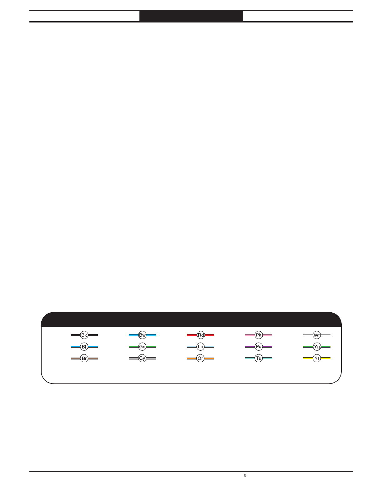
South Bend Tools
For Machines Mfd. Since 10/21 Model SB1118
Shock Hazard: It is extremely dangerous to
Wire Connections:
Modifications:
Motor Wiring:
junction box.
Circuit Requirements: Connecting the machine
power inverters store an electrical charge for
our Technical Support at (360) 734-1540.
ELECTRICAL
ELECTRICAL
Electrical Safety Instructions
These pages are accurate at the time of printing. In the constant effort to improve, however, we may
make changes to the electrical systems of future machines. Study this section carefully. If you see
differences between your machine and what is shown in this section, call Technical Support at (360)
734-1540 for assistance BEFORE making any changes to the wiring on your machine.
perform electrical or wiring tasks while the
machine is connected to the power source.
Touching electrified parts will result in
personal injury including but not limited to
severe burns, electrocution, or death. For
your own safety, disconnect machine from
the power source before servicing electrical
components or performing any wiring tasks!
All connections must be
tight to prevent wires from loosening during
machine operation. Double-check all wires
disconnected or connected during any wiring
task to ensure tight connections.
Using aftermarket parts or
modifying the wiring beyond what is shown
in the diagram may lead to unpredictable
results, including serious injury or fire.
The motor wiring shown in these
diagrams is current at the time of printing,
but it may not match your machine. Always
use the wiring diagram inside the motor
to an improperly sized circuit will greatly
increase the risk of fire. To minimize
this risk, only connect the machine to a
power circuit that meets the minimum
requirements given in this manual.
Capacitors/Inverters: Some capacitors and
up to 10 minutes after being disconnected
from the power source. To reduce the risk of
being shocked, wait at least this long before
working on capacitors.
Wire/Component Damage: Damaged wires
or components increase the risk of serious
personal injury, fire, or machine damage. If
you notice that any wires or components are
damaged while performing a wiring task,
replace those wires or components before
completing the task.
Experiencing Difficulties: If you are
experiencing difficulties understanding the
information included in this section, contact
BLACK
BLUE
BROWN
NOTICE:
WIRING DIAGRAM COLOR KEY
BLUE
WHITE
GREEN
G R AY
The photos and diagrams included in this section are best viewed in color. You can
see them in color at www.southbendtools.com.
RED
LIGHT
BLUE
ORANGE
PINK
PURPLE
TURQUIOSE
WHITE
YEL LOW
GREEN
YEL LOW
-59-
Page 68
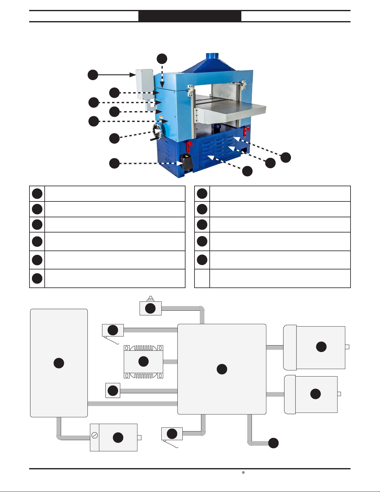
South Bend Tools
Model SB1118
8
Electrical Overview
ELECTRICAL
Electrical Overview
2
3
4
5
6
7
8
For Machines Mfd. Since 10/21
1
11
10
9
1
Headstock Cover Safety Switch (Page 66) Table Lower Limit Switch (Page 66)
2
Control Panel Box (Page 64) Power Supply Junction Box (Page 67)
3
Table Upper Limit Switch (Page 66) Table Motor (Page 65)
Transformer
4
(Page 66)
Table Magnetic Sensor
5
(Page 67)
Electrical Box
6
(Page 62)
1
3
2
4
7
8
9
10
Main Motor (Page 65)
11
Feed Motor (Page 67)
6
10
-60-
5
11
7
9
Page 69
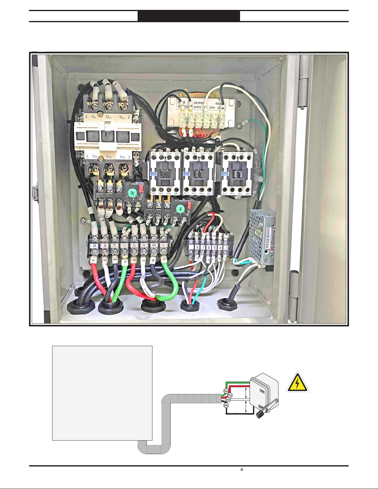
South Bend Tools
For Machines Mfd. Since 10/21 Model SB1118
ELECTRICAL
Electrical Box
Power supply wiring
Electrical Box
DISCONNECT
SWITCH
(as recommended
Ground
Hot
Hot
Hot
3-PHASE
220 VAC
)
-61-
Page 70
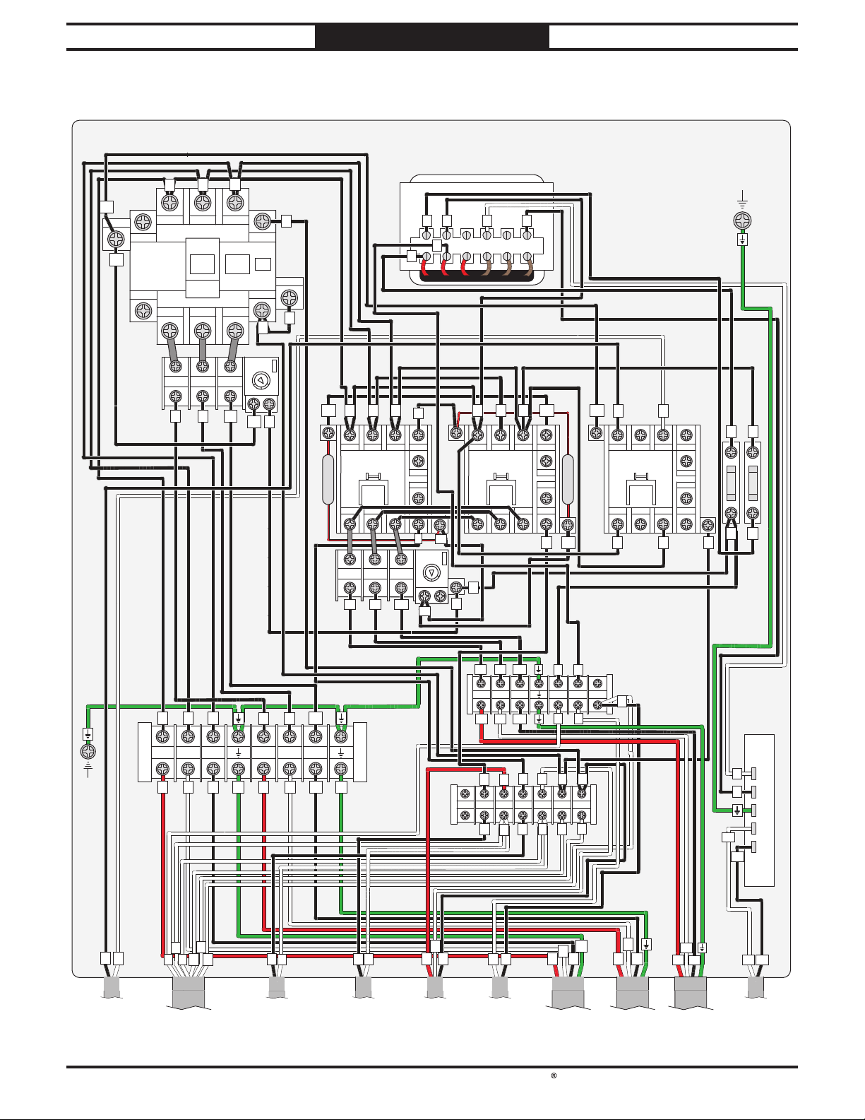
South Bend Tools
Model SB1118
Panel)
Motor)
Motor)
Supply)
ELECTRICAL
Electrical Box Wiring
Electrical Box Wiring Diagram
Electrical Box
For Machines Mfd. Since 10/21
16
16
16
A1
1/L1 5/L33/L2
7
Contactor
SDE
MA-55
8
2/T1
OL
Relay
SDE
RA-30
S
R
4/T2
1/2 3 /4 5/6
UWV
6/T3
0
95
L1/1 L3/5 21NCL2/3
T1/2
0
GDM 40VA
L N
R
S
Contactor
SDE MA-09
R
T2/4
GND
T
10
13
14
22NC
T3/6
8
17
16
R
L1/1 L3/5 21NCL2/3
Contactor
SDE MA-09
T2/4
T1/2
R
T
0
T
13
2A 250V
14
T3/6
22NC
Fuses
0
T
4
T
Transformer
T
3
13
B2
14
4
4
AMP
RESET
34
48
40
95
96
16
R S
0
10
Wave Filter
Cetus 0.1uF 120 Ohm
T1/2
OL Relay
SDE RA-20
U1 V1 W1
L1/1 L3/5 21NCL2/3
1/2 3/4 5/6
Contactor
SDE MA-09
T2/4
T
T3/6
220V440V0V 0V 24V 220V
R
T
1
0
9
13
14
22NC
6
17
AMP
RESET
1.6
2.5
2
98
96
17
GND
R
T
(To
Transformer)
Pg. 66
R S T
R S T U V W
R S T
4
7
0
3
5
2
UWV
U V
G
6
5
(To Upper
(To Control
Pg. 64
Limit Switch)
Pg. 66 Pg. 66 Pg. 64 Pg. 66 Pg. 66
G
W
8
(To Lower
Limit Switch)
U1 V1
W1
V1 W1 0 1 2U1
U1 V1 W1
7
1
0
Power
2
1
0
3
586
4
Supply
Mean Well
RS-15-24
L
N
5 4
8 7
6
6
8
7
5
7
7
3
(To LED,
3-Wire)
1
2
(To Safety
Switch)
3
3
5
4
G
RST
(To Power
V
U
W
(To Main
V1
U1
W1
(To Table
V-
V+
V-
(To LED,
2-Wire)
V+
Pg. 65 Pg. 66Pg. 61
-62-
Page 71
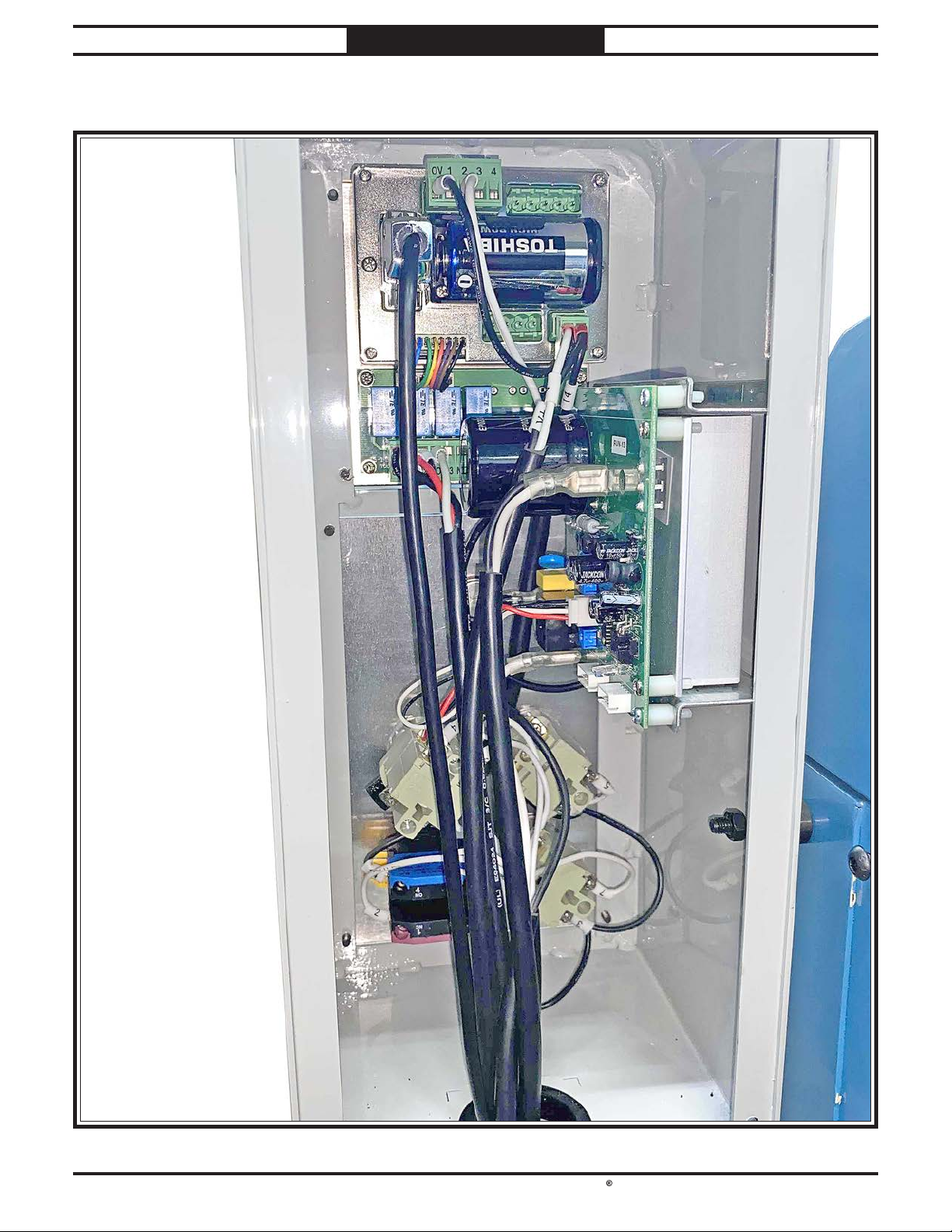
South Bend Tools
For Machines Mfd. Since 10/21 Model SB1118
ELECTRICAL
Control Box
-63-
Page 72
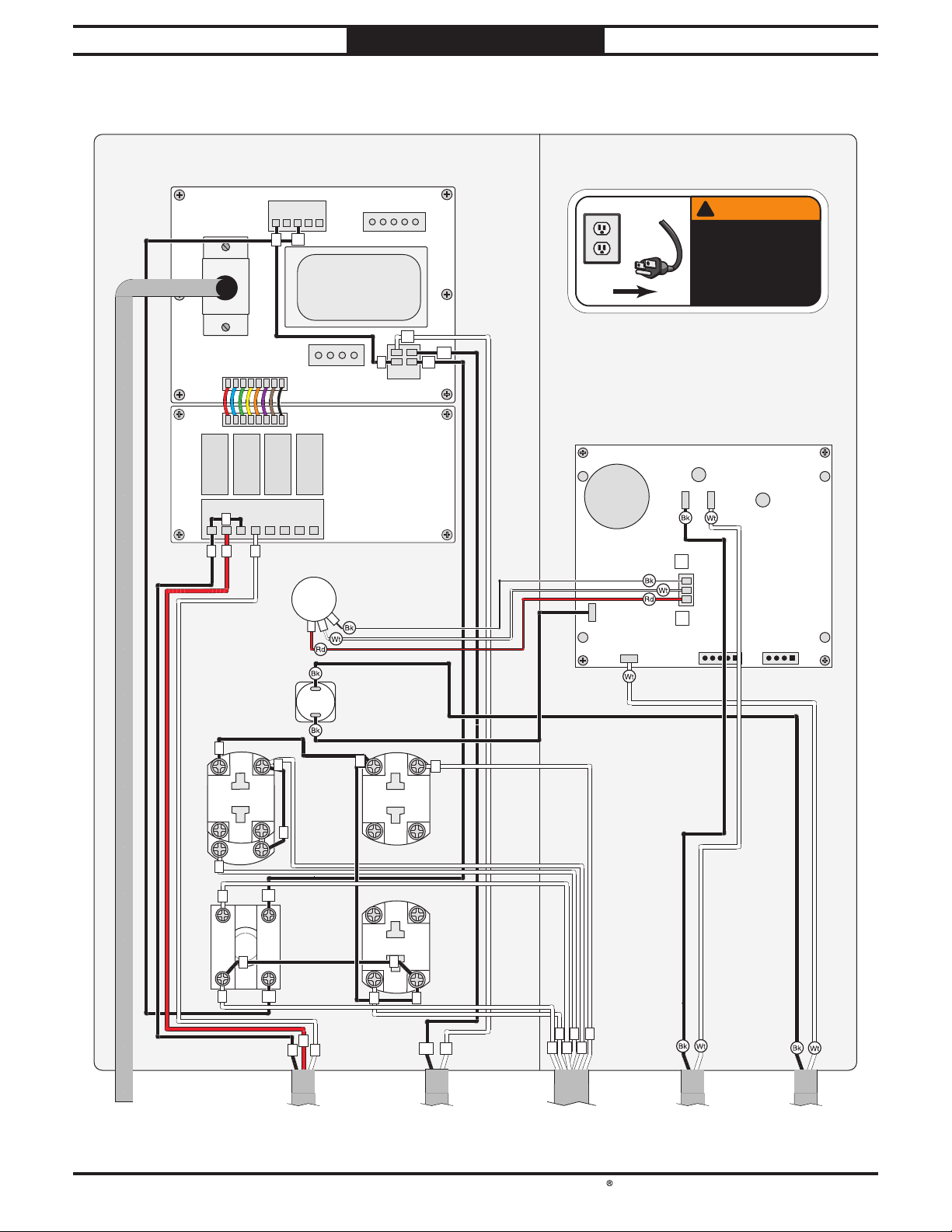
South Bend Tools
Model SB1118
ELECTRICAL
Control Box Wiring
Control Box Wiring Diagram
Control Panel
Digital Readout
M15S-DC24V
For Machines Mfd. Since 10/21
0V 1 2 3 4
13
0
C1 N0 C2 N0 C3 N0 C4 N0
3
735
D Battery
0
Circuit Board
Potentiometer
PWM 10 KOHM
!
WARNING!
!
V-
V+
14
24
0V
Low
T1
AC1
AC2
High
T2
SHOCK HAZARD!
Disconnect power
before working on
wiring.
M+ M-
T3 T4
VR2
P2
VR1
P1
Circuit Board
PWM AC 120V
P3
To Magnetic
Sensor
Pg. 67
MAIN MOTOR
Button
YK YS-PF1-3
3
4
14
10A 250VAC
22
0
13
TABLE UP
21
4
X1
X2
14
2
NO
4
3
EMERGENCY
NO
3
13
STOP Button
YIJIA LA36M
7
3
12
NCNC
3
To Electrical Box
(7-Post Terminal Bar)
Circuit Breaker
Zing Ear ZE-800
Button
YS-F1-3
5
3
14
10A 250VAC
22
21
10A 250VAC
13
7
13
21
22
3
14
3
V+
To Power Supply
Pg. 62
5
TAB LE
DOWN
Button
YS-F1-3
V-
540
7
3
2
To Electrical Box
(7-Post Terminal Bar)
Pg. 62Pg. 62
To Feed Motor
To Transformer
Pg. 66Pg. 60
-64-
Page 73
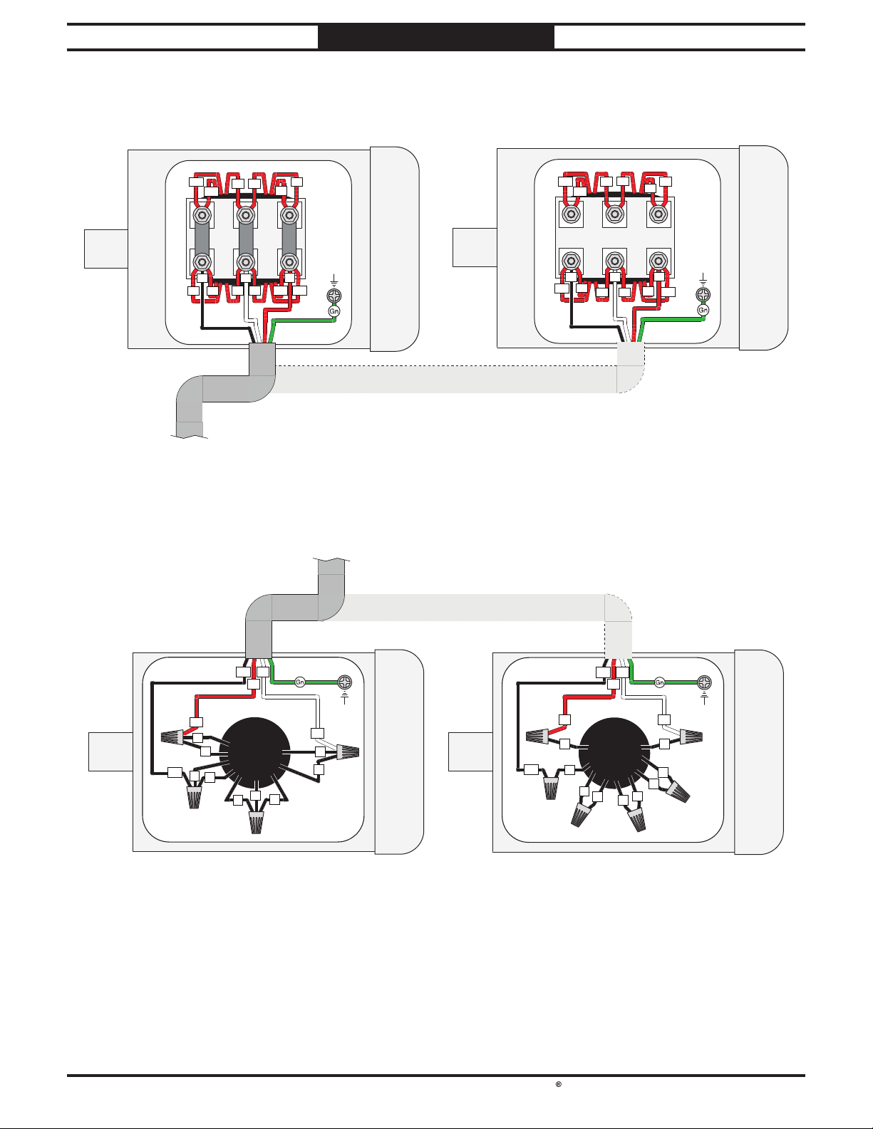
South Bend Tools
For Machines Mfd. Since 10/21 Model SB1118
ELECTRICAL
Motor Wiring
Main Motor Wiring Diagrams
220V 440V
U5
W6
U2
U6
W2
U1
V
V5 V1
W
W1
V6
V2
GND
U
W5
Rewired for 440V Operation
To Electrical Box
(Pg. 62)
Table Motor Wiring Diagrams
To Electrical Box
(Pg. 62)
W6
W5
U2
U5
W2
U1
V
U6
W
V2
V5
GND
U
V6
W1
V1
W1
Rewired for 440V Operation
V1
W1
U1
U1
9
1
7
3
5
4
6
GND
V1
8
2
W1
220V 440V
U1
V1
W1
U1
GND
V1
1
3
4
7
2
9
6
8
5
-65-
Page 74
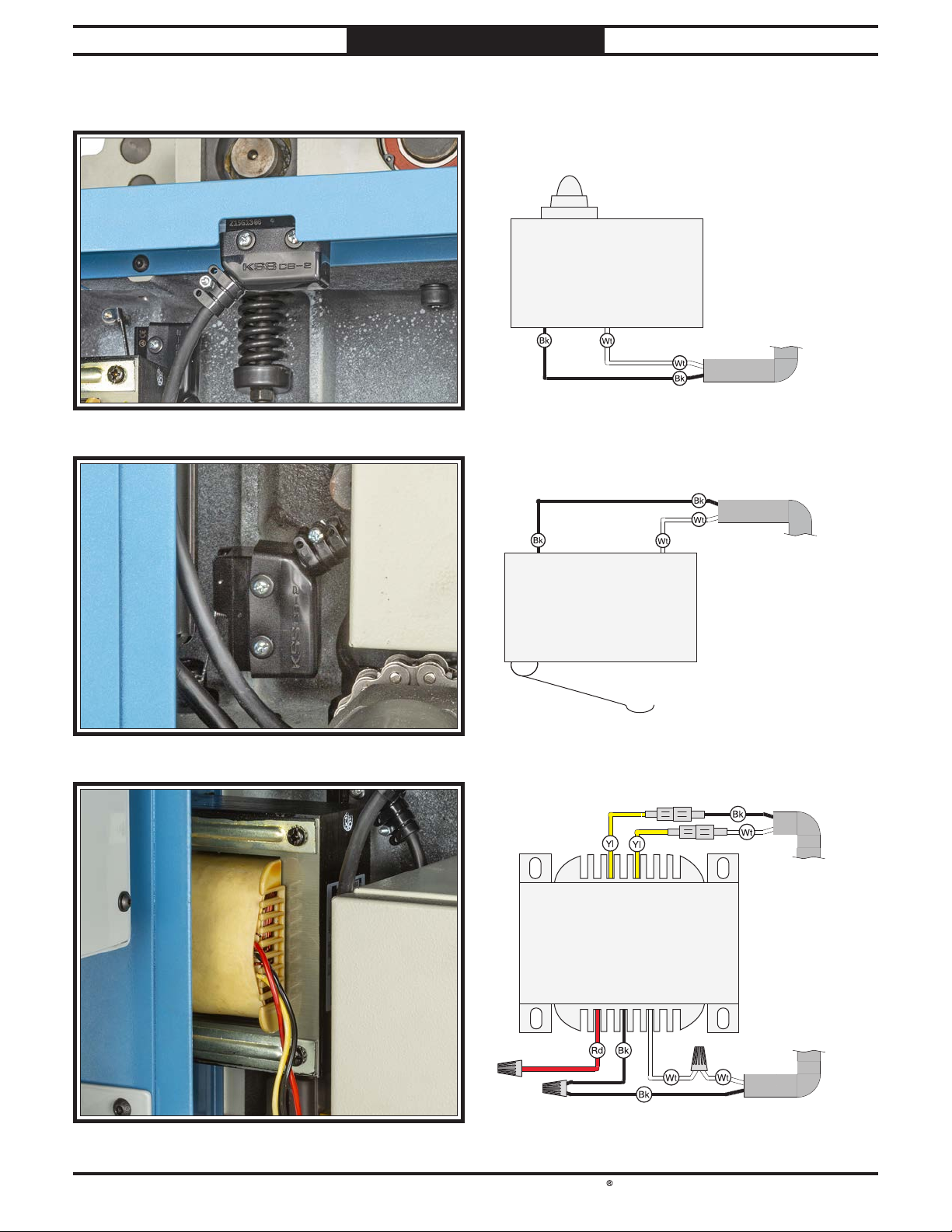
South Bend Tools
Model SB1118
Electrical Components
ELECTRICAL
For Machines Mfd. Since 10/21
Electrical Component Wiring Diagrams
Safety Switch
COM NO NC
COM NO NC
Table Limit Switch
Pg. 62
(To Electrical Box)
(To Electrical Box)
Pg. 62
-66-
(To Control Box)
Pg. 64
0 (Yellow) 110 (Yellow)
Transformer
440 (Red) 220 (Black) 0 (White)
Pg. 62
(To Electrical Box)
Page 75
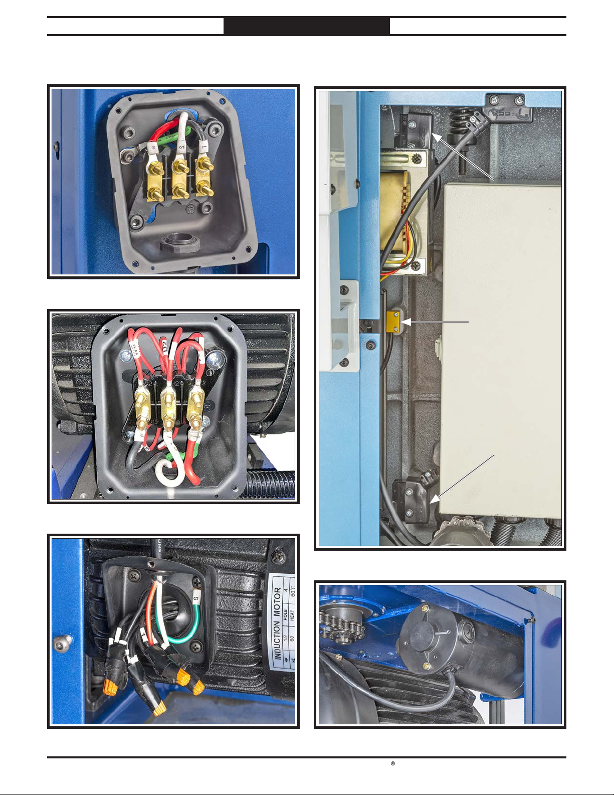
South Bend Tools
For Machines Mfd. Since 10/21 Model SB1118
Electrical Component Photos
ELECTRICAL
Electrical Component Photos
-67-
Page 76
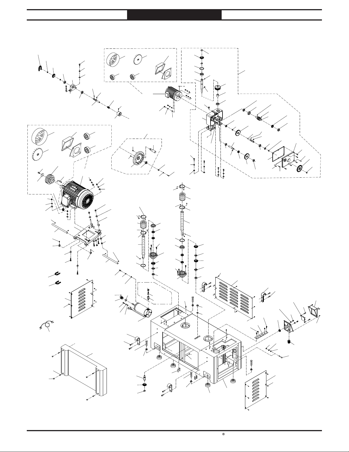
South Bend Tools
Model SB1118
PARTS
Base & Motors
PARTS
For Machines Mfd. Since 10/21
178
192-3
192-4
109
240
162
23
68
187
263
241
314
179
192-8
192-9
192-6
202
69
182
190
118
192-7
192-5
109
196
233
2
181
F
192-10
201
118
192
263
47
68
109
45
184
H
232
183
192-11
192-12
23
197
69
202
185
188
68
109
200
199
197
187
305
306
307
146
143-1
143-4
180-3
180-4
199
5
308
27
226
187
180-2
209
315
12
225
231
180-5
206
207
206
205
208
129
380
227
267
75
143-5
205
380-2
228
143-2
143
144
180
180-1
146
143-3
5
191
206
206
210
211
19
212
21
213
214
380-3
380-4
321
120
145
209
210
211
19
212
H
189
227
228
21
195
148
149
102
226
68
109
154
205
207
205
204
129
320
319
172
45
150
G
172
21
215
21
213
214
228
177
229
75
173
2
F
230
151
152
153
175
161
174
162
176
220
163
222
1
155
163
164
173
223
148
158
167
27
129
45
165
170
225
111
129
156
221
7
166
169
226
302
5
295
233
2
157
158
252
186
294
168
169
170
171
166
251
11
253
292
-68-
Page 77
South Bend Tools
For Machines Mfd. Since 10/21 Model SB1118
PARTS
Base & Motors Parts List
REF PAR T # DE SCR IPTION REF PAR T # DE SCR IPTION
1 PSB1118001 WORM GEARBOX ASSEMB LY 170 PSB1118170 ROLL PIN 6 X 25
2 PSB1118002 B UTTON HD CA P S CR M6-1 X 10 171 PSB1118171 SPROCKET 26T
5 PSB1118005 LOCK WASHER 8MM 172 PSB1118172 OIL PLUG 1/4" N PT
7 PSB1118007 H EX N UT M8-1 .25 173 PSB1118173 BA LL BEARING 6202ZZ
11 PSB1118011 CAP SCREW M8-1.25 X 25 174 PSB1118174 GEAR SHAFT
12 PSB1118012 FLAT WASHER 6MM 175 PSB1118175 KEY 5 X 5 X 20 RE
19 PSB1118019 CAP SCREW M8-1.25 X 20 176 PSB1118176 GEAR 20T
21 PSB1118021 SPROCKET 13T 177 PSB1118177 FLAT WASHER 17 X 35 X 2
23 PSB1118023 HEX NUT M10-1.5 178 PSB1118178 CH AIN #40 X 58P
27 PSB1118027 CAP SCREW M6-1 X 16 179 PSB1118179 SPROCKET 13T
45 PSB1118045 KEY 5 X 5 X 12 RE 180 PSB1118180 HANDWHEEL ASSEMBLY
47 PSB1118047 CAP SCREW M10-1.5 X 20 18 0-1 PSB1118180-1 F OLDIN G HAN DLE 28 X 90, M 6-1
68 PSB1118068 LOCK WAS HER 10MM 180-2 PSB1118180-2 F LAT HD SCR M6-1 X 12
69 PSB1118069 SET SCREW M8-1.25 X 10 180 -3 PSB1118180-3 ROLL PIN 8 X 1 8
75 PSB1118075 EXT RETA IN IN G RING 25MM 180-4 PSB1118180-4 HANDWHEEL TYPE-13 200D X 20B X M6-1
102 PSB1118102 KEY 5 X 5 X 20 RE 180-5 PSB1118180-5 BALL B EARING 600 4ZZ
109 PSB1118109 FLAT WASHER 10MM 181 PSB1118181 HANDWHEEL BRACKET
111 PSB1118111 SET SCREW M8 -1.25 X 10 182 PSB1118182 MA IN MOTOR CORD 8G 4W 60"
118 PSB1118118 BALL B EARING 6203-2N SE 183 PSB1118183 KEY 5 X 5 X 15 RE
120 PSB1118120 FLAT WASHER 8MM 184 PSB1118184 HANDWHEEL SHAFT
129 PSB1118129 KEY 5 X 5 X 10 RE 185 PSB1118185 COMPRESSION SPRING 1.2 X 23.4 X 40
143 PSB1118143 ELEVATION MOTOR 1/2 HP 220 /440 V 3-PH 186 PSB1118186 CAP SCREW M8-1.25 X 12
143-1 PSB1118143-1 MOTOR F AN COVER 187 PSB1118187 SET SCREW M6-1 X 16
143-2 PSB1118143-2 M OTOR F AN 188 PSB1118188 HANDWHEEL CONN ECTOR
143-3 PSB1118143-3 JUN CTION BOX 189 PSB1118189 ROLL PIN 8 X 20
143-4 PSB1118143-4 BALL B EARING 620 3ZZ (F RONT) 190 PSB1118190 CAP SCREW M6-1 X 10
143-5 PSB1118143-5 BALL B EARING 620 2Z Z (REAR) 1 91 PSB1118191 FLAT WASHER 6MM
144 PSB1118144 HEX BOLT M8-1.25 X 25 192 PSB1118192 MAIN MOTOR 15H P 2 20/ 440V 3-PH
145 PSB1118145 CAP SCREW M6-1 X 20 192-3 PSB1118192-3 CAP SCREW M10-1.5 X 20
146 PSB1118146 LOCK WASH ER 6MM 192-4 PSB1118192-4 FENDER WASH ER 11 X 53 X 3
148 PSB1118148 B ALL BEARIN G 6205Z Z 192-5 PSB1118192-5 KEY 10 X 8 X 56 RE
149 PSB1118149 GEAR SHAFT 192-6 PSB1118192-6 GROMMET 24MM
150 PSB1118150 KEY 5 X 5 X 22 RE 192 -7 PSB1118192-7 MOTOR PULLEY
151 PSB1118151 WORM GEA R 1 92-8 PSB1118192-8 M OTOR F A N COVER
152 PSB1118152 BUSHING 192-9 PSB1118192-9 MOTOR F AN
153 PSB1118153 B ALL BEARIN G 6204Z Z 192-10 PSB1118192-10 JUNCTI ON BOX
154 PSB1118154 WORM GEARB OX 192-11 PSB1118192-11 BALL B EARING 620 8ZZ (FRONT)
155 PSB1118155 OIL SEA L TC 25 X 40 X 8 192-12 PSB1118192-12 B ALL BEA RIN G 6206ZZ (REA R)
156 PSB1118156 WORM SHAFT 195 PSB1118195 INT RETAINING RIN G 52MM
157 PSB1118157 GE AR 24T 1 96 PSB1118196 HEX BOLT M10-1.5 X 50
158 PSB1118158 B ALL BEARIN G 6203ZZ 197 PSB1118197 HEX NUT M12-1.75
161 PSB1118161 B ALL BEA RIN G 6201ZZ 1 99 PSB1118199 FLAT WASHER 12MM
162 PSB1118162 EXT RETAIN ING RING 16MM 200 PSB1118200 ADJUSTING SHAFT
163 PSB1118163 GEA R 60 T 201 PSB1118201 MOTOR MOUNTING PLATE
164 PSB1118164 GEAR SHAFT 202 PSB1118202 SHAFT
165 PSB1118165 OIL S EAL SC 17 X 30 X 8 204 PSB1118204 LEADSCREW (RIGHT)
166 PSB1118166 EXT RETAINING RIN G 17MM 205 PSB1118205 MOUNTING RING
167 PSB1118167 GASKET 206 PSB1118206 FLAN GE BOLT M4-.7 X 8
168 PSB1118168 GEARBOX COVER 207 PSB1118207 DUST BOOT
169 PSB1118169 CAP SCREW M6-1 X 26 208 PSB1118208 LEADSCREW (LEFT)
-69-
Page 78
South Bend Tools
Model SB1118
PARTS
For Machines Mfd. Since 10/21
Base & Motors Parts List (Cont.)
REF PAR T # DE SCR IPT ION REF PAR T # DE SCRIPTION
209 PSB1118209 INT RETAINING RING 68MM 251 PSB1118251 POWER S UPPLY JUNCTION BOX
210 PSB1118210 B ALL BEARIN G 60 08 -2NS E 252 PSB1118252 TERMIN AL B LOCK
211 PSB1118211 THRUS T BEARING 51105 253 PSB1118253 B UTTON HD CA P S CR M5-.8 X 10
212 PSB1118212 BUSHING 263 PSB1118263 SPACER
213 PSB1118213 EXT TOOTH WAS HER 25MM 267 PSB1118267 IDLER SPROCKET 13T
214 PSB1118214 LEADSCREW NUT M25-1.5 292 PSB1118292 STRAIN RELIEF TYPE-3 PGA21
215 PSB1118215 S PROCKET PLATE 294 PSB1118294 HEX BOLT M8-1.25 X 50
220 PSB1118220 BASE COVER, REAR 295 PSB1118295 FLAT WASHER 8MM
221 PSB1118221 GROMMET 24MM 302 PSB1118302 EXT TOOTH WASH ER 8 MM
222 PSB1118222 GROMMET 16MM 305 PSB1118305 CAP SCREW M8-1.25 X 16
223 PSB1118223 PLA TE 30 6 PSB1118306 SET SCREW M5-.8 X 5
225 PSB1118225 LIFTIN G HOOK 307 PSB1118307 PULLEY
226 PSB1118226 CAP SCREW M10-1.5 X 30 308 PSB1118308 FLAT WASHER 8MM
227 PSB1118227 HEX BOLT M16-2 X 55 31 4 PSB1118314 PLUG 13MM
228 PSB1118228 HEX NUT M1 6-2 315 PSB1118315 FLAT WASHER 14 X 35 X 1
229 PSB1118229 FOOT 31 9 PSB1118319 EXT TOOTH WASHER 4MM
230 PSB1118230 BASE 320 PSB1118320 BUTTON HD CAP SCR M4-.7 X 8
231 PSB1118231 SPROCKET SHAFT 321 PSB1118321 CABLE TIE 300MM
232 PSB1118232 BAS E COVER, F RON T 380 PSB1118380 F EED MOTOR 3/4HP 220 V 1-PH
233 PSB1118233 BASE COVER, SIDE 380 -2 PSB1118380-2 BRUSH CAP
240 PSB1118240 CH AIN #40 X 54P 380-3 PSB1118380-3 BRUSH
241 PSB1118241 CHAIN #40 X 84P 38 0-4 PSB1118380-4 BRUSH HOLDER
-70-
Page 79
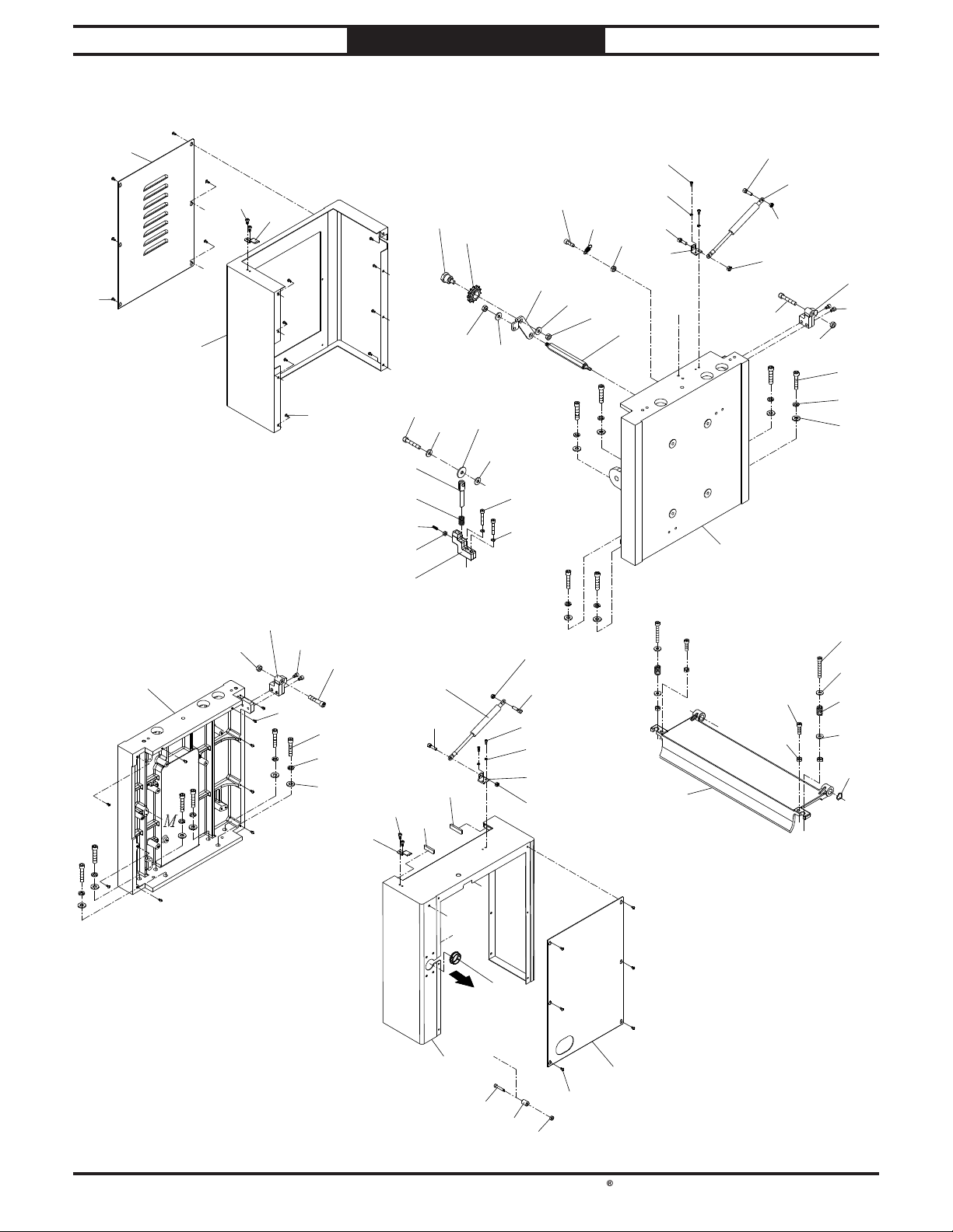
South Bend Tools
For Machines Mfd. Since 10/21 Model SB1118
28
PARTS
Column
24
110
238
238
J
257
239
6
64
224
249
198
199
36
190
244
2
37
2
194
219
245
28
160
17
20
242
267
224
N
22
234
242
236
250
16
22
23
142
5
13
14
110
23
15
N
95
101
224
6
64
257
J
2
249
198
199
244
190
239
110
254
262
Y
X
W
104
317
311
Y
316
238
110
13
14
15
238
50
C
51
105
2
23
48
22
49
22
70
D
-71-
Page 80
South Bend Tools
Model SB1118
PARTS
For Machines Mfd. Since 10/21
Column Parts List
REF PAR T # D ESCRIPTION REF PAR T # DE SCRIPT ION
2 PSB1118002 BUTTON H D CAP SCR M6-1 X 10 110 PSB1118110 CAP SCREW M8-1.25 X 25
5 PSB1118005 LOCK WASHER 8MM 142 PSB1118142 CAP SCREW M8-1.25 X 40
6 PSB1118006 H INGE 160 PSB1118160 STEP BRACKET
13 PSB1118013 CAP SCREW M5-.8 X 12 190 PSB1118190 CAP SCREW M6-1 X 10
14 PSB1118014 LOCK WASHER 5MM 1 94 PSB1118194 SHAFT
15 PSB1118015 GA S S PRIN G MOUN T 198 PSB1118198 LOCK WASHER 12MM
16 PSB1118016 SPROC KET MOUNT 199 PSB1118199 FLAT WASHER 12MM
17 PSB1118017 CAP SCREW M10-1.5 X 35 219 PSB1118219 COMPRESSION SPRING 2 X 17.6 X 44
20 PSB1118020 S PROCKET B OLT 224 PSB1118224 LOCK NUT M10-1.5
22 PSB1118022 FLAT WASHER 10MM 234 PSB1118234 FEN DER WASHER 11 X 53 X 3
23 PSB1118023 HEX NUT M10-1.5 236 PSB1118236 CAP SCREW M10-1.5 X 45
24 PSB1118024 LEFT COLUMN 238 PSB1118238 H EX N UT M8-1.25
28 PSB1118028 HEX N UT M6 -1 239 PSB1118239 GA S SPRIN G 20K G 292L
36 PSB1118036 ACCESS PANEL, UPPER LEFT 242 PSB1118242 FLAT WASHER 10MM
37 PSB1118037 HOUSIN G, UPPER LEFT 244 PSB1118244 PLATE
48 PSB1118048 CAP SCREW M10-1.5 X 75 245 PSB1118245 S ET SCREW M6-1 X 20
49 PSB1118049 COMPRESSION SPRING 3 X 20 X 35.5 249 PSB1118249 CAP SCREW M12-1.75 X 40
50 PSB1118050 CAP SCREW M10-1.5 X 40 250 PSB1118250 EXTENSION SPRING 1.2 X 11.5 X 34.2
51 PSB1118051 PRES SURE BAR 254 PSB1118254 PAD 40 X 10 X 2
64 PSB1118064 CAP SCREW M8-1.25 X 35 257 PSB1118257 HEX BOLT M10-1.5 X 70
70 PSB1118070 WA VY WASH ER 6MM 262 PSB1118262 PA D 33 X 1 0 X 2
95 PSB1118095 STANDOFF-HEX MM M10-1.5 X 20, 175 267 PSB1118267 IDLER SPROCKET 13T
101 PSB1118101 RIGHT COLUMN 31 1 PSB1118311 GROMMET 38MM
104 PSB1118104 HOUSING, UPPER RIGHT 316 PSB1118316 S PACER 6.5 X 15 X 20
105 PSB1118105 ACCESS PAN EL, UPPER RIGHT 317 PSB1118317 CAP SCREW M6-1 X 35
-72-
Page 81
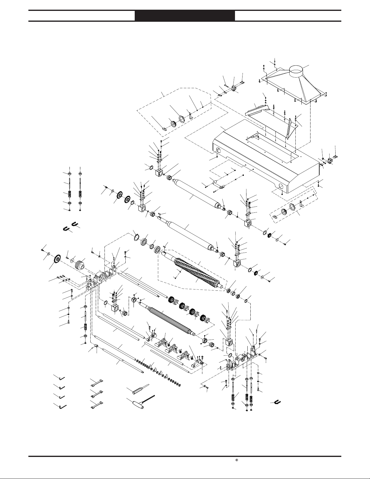
South Bend Tools
For Machines Mfd. Since 10/21 Model SB1118
23
PARTS
Headstock
103
159-2
159
159-4
159-1
159-6
159-3
159-5
12
257
5
7
4
6
J
103
3
40
146
234
235
218
47
285
286
275
276
22
268
22
68
236
82
83
84
82
23
68
237
303
8
42
69
43
193
57
58-3
58-2
78
87
91
42
57
39
28
130
88
80
193
44
54
89
169
58-1
61
193
22
58
E
9
10
130
47
69
69
189
268
193
45
193
39
28
76
94
12
45
42
43
68
146
310
130
297
318
146
310
130
309
L
55
63
309
E
84
146
82
83
82
309
297
55
310
81
D
69
L
L
39
28
42
43
53
297
43
189
39
28
42
94
21
47
106
22
68
50
94
268
68
22
21
46
19
297
309
146
310
P
65
69
82
83
84
82
23
Q
255
277
278
279
178
66
E
258
47
79
46
189
A
P
90
52
Q
297
43
73
309
94
69
72
C
309
42
193
130
90
280
281
B
22
B
39
28
94
146
310
293
146
310
268
68
73
76
74
94
297
69
91
A
130
74
226
85
92
39
28
43
56
67
77
E
93
46
19
12
159
5
224
7
41
4
6
J
18
-73-
Page 82
South Bend Tools
Model SB1118
PARTS
For Machines Mfd. Since 10/21
Headstock Parts List
REF PART # DE SCR IPTION REF PART # DE SCR IPTION
3 PSB1118003 DEFLECTION PLATE 83 PSB1118083 SHAFT
4 PSB1118004 CAP SCREW M8-1.25 X 30 84 PSB1118084 COMPRESSION SPRING 5 X 29 X 90
5 PSB1118005 LOCK WASHER 8MM 85 PSB1118085 BRACKET LEFT
6 PSB1118006 H INGE 87 PSB1118087 PRESSURE ARM
7 PSB1118007 H EX NUT M8-1.25 88 PSB1118088 TORS ION SPRING
8 PSB1118008 TOP COVER 89 PSB1118089 BRACKET RIGHT
9 PSB1118009 PAD 90 PSB1118090 SHAFT
10 PSB1118010 HA N DLE 91 PSB1118091 SHAFT
12 PSB1118012 FLAT WASHER 6MM 92 PSB1118092 COLLAR
18 PSB1118018 HEX N UT M5-.8 93 PSB1118093 ANTI-KICKB ACK PAWL
19 PSB1118019 CAP SCREW M8-1.25 X 20 94 PSB1118094 IN T RETAINING RING 47MM
21 PSB1118021 SPROCKET 13T 103 PSB1118103 B UTTON HD CA P S CR M 6-1 X 12
22 PSB1118022 FLAT WASHER 10MM 106 PSB1118106 CHAIN #40 X 24P
23 PSB1118023 HEX NUT M10-1.5 130 PSB1118130 EXT RETAIN ING RING 30MM
28 PSB1118028 HEX NUT M6-1 146 PSB1118146 LOCK WASH ER 6MM
39 PSB1118039 SET SCREW M6-1 X 30 159 PSB1118159 KNOB ASSEMBLY
40 PSB1118040 DUST PORT 6" 1 59-1 PSB1118159-1 BEZEL
41 PSB1118041 HEX BOLT M5-.8 X 25 159-2 PSB1118159-2 DIAL
42 PSB1118042 PLATE 1 59-3 PSB1118159-3 BRACKET
43 PSB1118043 BEARING BLOCK 159-4 PSB1118159-4 BEZEL NUT
44 PSB1118044 REAR ROLLER 1 59-5 PSB1118159-5 B UTTON H D CAP SCR M6-1 X 10
45 PSB1118045 KEY 5 X 5 X 12 RE 159-6 PSB1118159-6 FLAT WASHER 6MM
46 PSB1118046 F ENDER WAS HER 8.5 X 30 X 3.3 169 PSB1118169 CAP SCREW M6-1 X 26
47 PSB1118047 CAP SCREW M10-1.5 X 20 178 PSB1118178 CHA IN #40 X 58P
50 PSB1118050 CAP SCREW M10-1.5 X 40 189 PSB1118189 ROLL PIN 8 X 20
52 PSB1118052 SPROCKET 22T 193 PSB1118193 B ALL BEARIN G 6906ZZ
53 PSB1118053 EXT RETAINING RING 62MM 218 PSB1118218 SPROCKET 26T
54 PSB1118054 LONG REAR ROLLER 224 PSB1118224 LOCK NUT M10-1.5
55 PSB1118055 BALL B EARING 6007-2N SE 226 PSB1118226 CAP SCREW M10-1.5 X 30
56 PSB1118056 B ALL BEA RIN G 6010 -2N SE 234 PSB1118234 FENDER WASHER 11 X 53 X 3
57 PSB1118057 KEY 8 X 7 X 35 RE 235 PSB1118235 CAP SCREW M10-1.5 X 20
58 PSB1118058 HELICAL CUTTERHEAD ASSEMBLY 236 PSB1118236 CAP SCREW M10-1.5 X 45
58-1 PSB1118058-1 HELICA L CUTTERH EAD 25" 237 PSB1118237 CHAIN #40 X 74P
58-2 PSB1118058-2 FLA T HD TORX SCR #10-32 X 1/2 255 PSB1118255 S ET SCREW M4-.7 X 6
58-3 PSB1118058-3 C ARB IDE INSERT 1 5 X 15 X 2.5MM 257 PSB1118257 HEX BOLT M10-1.5 X 70
61 PSB1118061 RUB B ER PIN 258 PSB1118258 CAP SCREW M8-1.25 X 20
63 PSB1118063 COLLAR 268 PSB1118268 CAP SCREW M10-1.5 X 50
65 PSB1118065 FENDER WASHER 11 X 53 X 3 275 PSB1118275 HEX WRENCH 5MM
66 PSB1118066 CUTTERHEAD PULLEY 276 PSB1118276 HEX WRENCH 8 MM
67 PSB1118067 BUSHING 2 77 PSB1118277 WRENCH 12 X 14MM OPEN-ENDS
68 PSB1118068 LOCK WASHER 10MM 278 PSB1118278 WRENCH 17 X 19MM OPEN-EN DS
69 PSB1118069 S ET SCREW M8-1 .25 X 10 279 PSB1118279 WRENCH 22 X 24MM OPEN-ENDS
72 PSB1118072 MOUNTIN G BRACKET, LEFT 280 PSB1118280 FLA T SCREWDRIVER #1
73 PSB1118073 SHAFT 281 PSB1118281 TORX DRIVER T-25
74 PSB1118074 SHAFT 285 PSB1118285 HEX WRENCH 3MM
76 PSB1118076 COLLAR 286 PSB1118286 HEX WRENCH 4MM
77 PSB1118077 KEY 8 X 7 X 16 RE 293 PSB1118293 EXT RETA IN IN G RING 90MM
78 PSB1118078 SHAFT 297 PSB1118297 OIL CUP 3/16"
79 PSB1118079 BUSHING 303 PSB1118303 CAP SCREW M10-1.5 X 20
80 PSB1118080 INFEED ROLLER 309 PSB1118309 CAP SCREW M6-1 X 20
81 PSB1118081 M OUNTING B RACKET, RIGHT 310 PSB1118310 FLAT WASHER 6MM
82 PSB1118082 PLATE 31 8 PSB1118318 LOC K N UT M6-1
-74 -
Page 83
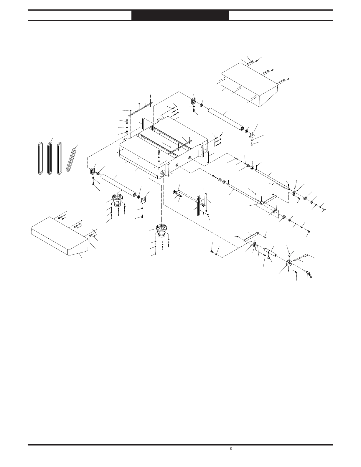
South Bend Tools
For Machines Mfd. Since 10/21 Model SB1118
PARTS
Table
26
118
38
117
23
116
216
217
259
264
260
112
114
113
115
112
199
U
117
7
23
U
113
118
116
115
31
119
7
5
121
7
120
129
125
32
133
122
126
129
32
129
7
125
147
127
124
128
134
135
126
122
138
32
137
139
127
121
120
136
126
47
125
120
5
305
30
140
122
121
5
305
29
60
59
62
266
47
114
305
124
22
V
117
118
119
108
23
116
141
V
199
31
71
5
142
38
26
118
117
23
116
141
71
5
142
132
14
14
96
265
-75-
Page 84
South Bend Tools
Model SB1118
PARTS
For Machines Mfd. Since 10/21
Table Parts List
REF PART # DE SCR IPTION REF PART # DE SCR IPTION
5 PSB1118005 LOCK WASHER 8MM 122 PSB1118122 CAM
7 PSB1118007 HEX N UT M8-1 .25 124 PSB1118124 ROLLER
14 PSB1118014 LOCK WASHER 5MM 125 PSB1118125 SET S CREW M5-.8 X 8
22 PSB1118022 FLAT WASHER 10MM 126 PSB1118126 PLATE
23 PSB1118023 HEX NUT M10-1.5 127 PSB1118127 SHOULDER BOLT M8-1.25 X 8, 14 X 18
26 PSB1118026 HEX B OLT M12-1.75 X 50 128 PSB1118128 BRACKET
29 PSB1118029 KN OB 3/8-16, D1-1/4, TAPERED 129 PSB1118129 KEY 5 X 5 X 10 RE
30 PSB1118030 SHA FT 3/8-16, 5-7/8L 132 PSB1118132 SCALE BRACKET
31 PSB1118031 EXTENSION TABLE 133 PSB1118133 BRACKET
32 PSB1118032 ROLL PIN 5 X 25 1 34 PSB1118134 HUB SHAFT
38 PSB1118038 S ET SCREW M10 -1.5 X 20 135 PSB1118135 E-CLIP 24MM
47 PSB1118047 CAP SCREW M10-1.5 X 20 136 PSB1118136 POIN TER
59 PSB1118059 WAVY WASH ER 6MM 137 PSB1118137 BUTTON H D CAP SCR M4-.7 X 6
60 PSB1118060 CAP SCREW M5-.8 X 10 138 PSB1118138 HUB
62 PSB1118062 SH OULDER BOLT M 5-. 8 X 7, 10 X 4 139 PSB1118139 SET SCREW M6 -1 X 8
71 PSB1118071 FLAT WASHER 8MM 140 PSB1118140 A DJ HAN DLE M10 -1.5 X 50, 75L
96 PSB1118096 CAP SCREW M5-.8 X 10 141 PSB1118141 HOUSING BRACKET
108 PSB1118108 MAIN TABLE 1 42 PSB1118142 CAP SCREW M8-1.25 X 40
112 PSB1118112 CAP SCREW M5-.8 X 16 147 PSB1118147 SHOULDER B OLT M8-1.2 5 X 8, 14 X 24
113 PSB1118113 GUIDE P LA TE 1 99 PSB1118199 FLAT WASHER 12MM
114 PSB1118114 GI B 216 PSB1118216 V-B ELT A 8 1
115 PSB1118115 S ET SCREW M8-1 .25 X 40 217 PSB1118217 V-BELT 3GT-720 -15
116 PSB1118116 HEX BOLT M10-1.5 X 30 259 PSB1118259 SHOULDER BOLT M10-1.5 X 20, 16 X 22
117 PSB1118117 ROLLER BRACKET 260 PSB1118260 SPACER 26 X 20 X 12
118 PSB1118118 BALL B EARING 620 3-2N SE 264 PSB1118264 E-CLIP 8MM
119 PSB1118119 ROLLER 265 PSB1118265 BRACKET
120 PSB1118120 FLAT WASHER 8MM 266 PSB1118266 MAGNETIC STRIP
121 PSB1118121 SHAFT 30 5 PSB1118305 CAP SCREW M8-1.25 X 16
-76-
Page 85
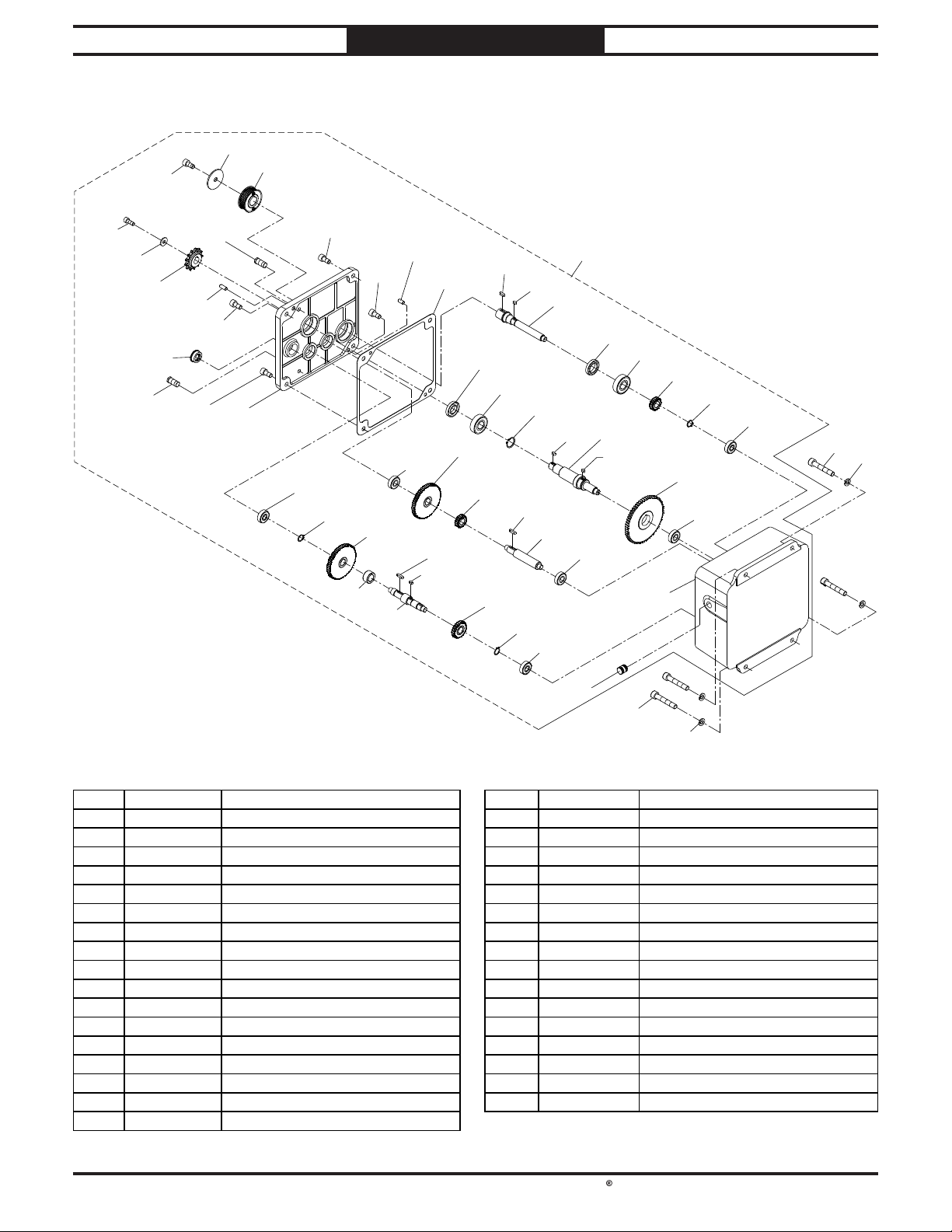
South Bend Tools
For Machines Mfd. Since 10/21 Model SB1118
68
PARTS
Gearbox
107-2
107-1
107-3
107-4
107-5
107-6
107-26
107-31
107-7
107-1
107-1
107-31
107-8
107-16
107-1
107-15
107-27
107-1
107-23
107-28
107-7
107-16
107-24
107-9
107-23
107-11
107-10
107-17
107-13
107-14
107-30
107-11
107-18
107-24
107-25
107-15
107-16
107-22
107-11
107-16
107
107-12
107-13
107-32
107-29
107-14
107-21
107-16
107-15
107-16
17
68
107-19
17
REF PAR T # DESCRIPT ION REF PART # DE SCRIPT ION
17 PSB1118017 CAP SCREW M10-1.5 X 35 107-16 PSB1118107-16 B ALL BEA RIN G 6201-2N SE
68 PSB1118068 LOCK WASH ER 10MM 107-17 PSB1118107-17 OIL SEAL TC 20 X 40 X 7
107 PSB1118107 GEARBOX ASS EMBLY 107-18 PSB1118107-18 EXT RETA IN IN G RING 25MM
10 7-1 PSB1118107-1 CAP SCREW M10-1.5 X 20 107-19 PSB1118107-19 PLUG 16M M
10 7-2 PSB1118107-2 FLAT WASHER 10 X 25 X 3 10 7-2 0 PSB1118107-20 GEAR SHAFT
10 7-3 PSB1118107-3 PULLEY 10 7-2 1 PSB1118107-21 GEA R 6 4T
10 7-4 PSB1118107-4 CAP SCREW M8-1.25 X 20 1 0 7-22 PSB1118107-22 GEAR SHAFT
10 7-5 PSB1118107-5 FLAT WASHER 8MM 10 7-23 PSB1118107-23 GEAR 60 T
10 7-6 PSB1118107-6 S PROCKET 13T 107-24 PSB1118107-24 KEY 5 X 5 X 20 RE
10 7-7 PSB1118107-7 ROLL PIN 8 X 18 10 7-25 PSB1118107-25 GEAR SHAFT
10 7-8 PSB1118107-8 GEARBOX COVER 107-26 PSB1118107-26 OIL SIGHT GLASS 29MM
10 7-9 PSB1118107-9 GASKET 10 7-2 7 PSB1118107-27 BUSHING
107-10 PSB1118107-10 KEY 5 X 5 X 16 RE 10 7-2 8 PSB1118107-28 GEAR SHAFT
107-11 PSB1118107-11 KEY 5 X 5 X 10 RE 107-29 PSB1118107-29 GEARB OX
107-12 PSB1118107-12 OIL SEAL TC 24 X 40 X 7 1 07-30 PSB1118107-30 GEAR 24 T
107-13 PSB1118107-13 BALL B EARING 6204-2N SE 107-31 PSB1118107-31 OIL PLUG 1/4" NPT
107-14 PSB1118107-14 GEAR 20T 10 7-32 PSB1118107-32 KEY 5 X 5 X 8 RE
107-15 PSB1118107-15 EXT RETAINING RIN G 16 MM
-77-
Page 86
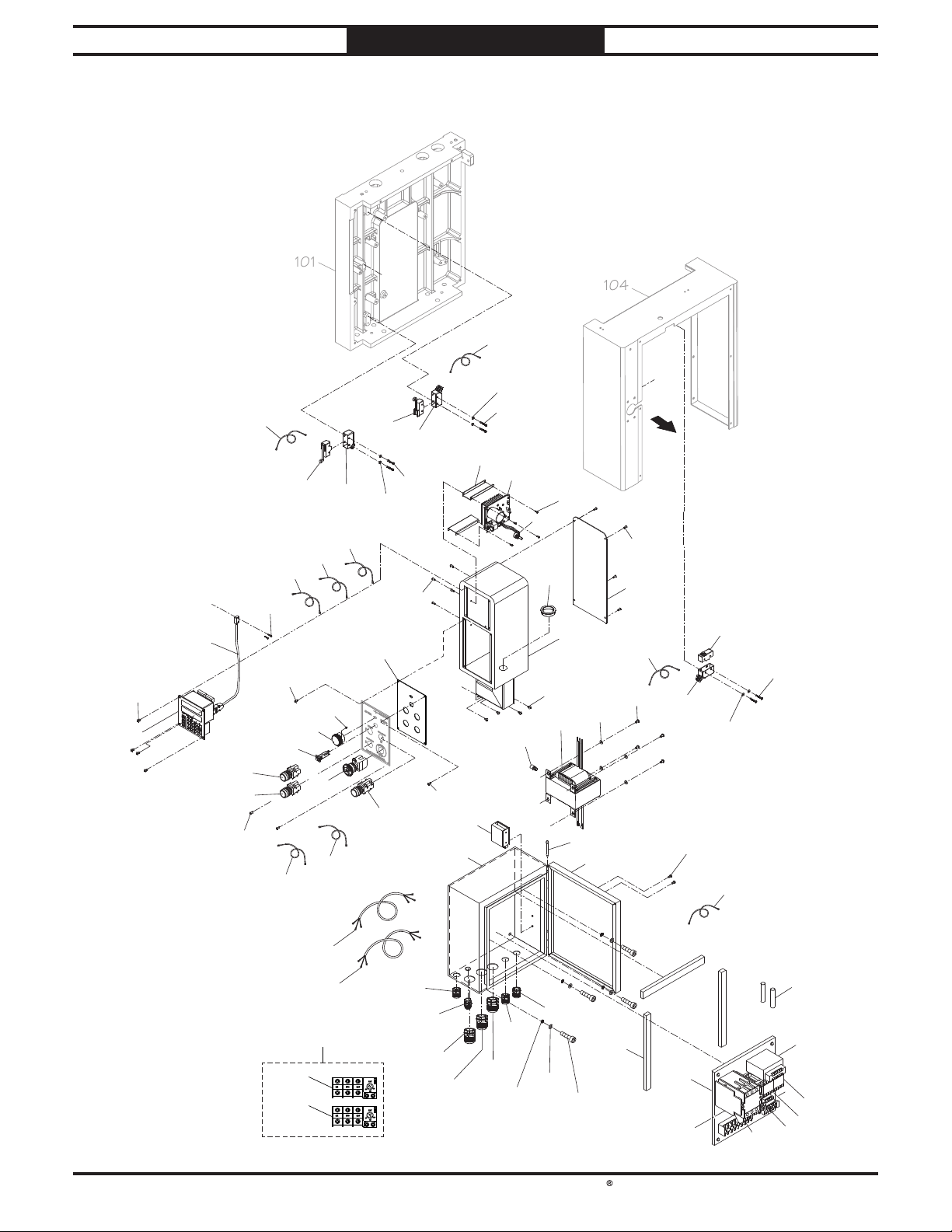
South Bend Tools
Model SB1118
333
101M104
PARTS
Electrical Components
For Machines Mfd. Since 10/21
356
368
346
347
X
W
355
358
243
97
359
376
358
359
97
243
364
377
365
370
371
372
M
98
368
339
368
W
374
373
375
369
366
2
378
379
313
368
367
357
253
353
97
359
243
343
344
342
345
341
368
337
348
X
337-2
349
337-1
338
343
368
-78-
381-1
381-2
361
363
381
1/2 3/4 5/6
1/2 3/4 5/6
350
362
350
360
350
351
AMP
RESET
18
26
22
98
96
AMP
RESET
0.9
1.5
1.3
98
96
352
352
256
301
354
331
247
332
336
334
382
335
Page 87
South Bend Tools
For Machines Mfd. Since 10/21 Model SB1118
PARTS
Electrical Components Parts List
REF PAR T # DE SCR IPTION REF PART # DESCRIPT ION
2 PSB1118002 BUTTON HD CAP SCR M6-1 X 1 0 353 PSB1118353 LIMIT SWITCH MJ2-1307 15A 125V
97 PSB1118097 PHLP HD SCR M4-.7 X 30 354 PSB1118354 COVER P A D
98 PSB1118098 BUTTON HD CA P S CR M3-.5 X 1 5 355 PSB1118355 CORD 18G 2W 23-5/8" CSA
243 PSB1118243 FLAT WASHER 4MM 356 PSB1118356 CORD 18G 2W 37-3/8" CSA
247 PSB1118247 CAP SCREW M6-1 X 12 357 PSB1118357 CORD 18G 2W 38-1/4" CSA
253 PSB1118253 B UTTON HD CAP SCR M 5-.8 X 10 358 PSB1118358 LIMIT SWITCH MJ2-1703 15A 125V
256 PSB1118256 FLAT WASHER 6MM 359 PSB1118359 LIMIT SWITCH HOUSING KSSCB-2
301 PSB1118301 EXT TOOTH WAS HER 6MM 36 0 PSB1118360 FUSE 2A 250V
313 PSB1118313 FLAT WASHER 5MM 361 PSB1118361 CORD 16G 4W 34-5/8" CSA
331 PSB1118331 ELECTRICAL PANEL 362 PSB1118362 STRAIN RELIEF TYPE-3 M16-1.5
332 PSB1118332 CONTACTOR SDE MA-55 220V 36 3 PSB1118363 CORD 16G 2W 43-5/16" CSA
333 PSB1118333 OL SDE RA -30 34-48 A 364 PSB1118364 CIRCUIT BOARD PWM (AC 120V)
334 PSB1118334 CONTACTOR SDE MA-09 220-240V 365 PSB1118365 POTEN TIOMETER PWM 1 0 KOHM
335 PSB1118335 OL SDE RA-20 1.6-2.5A 366 PSB1118366 CONTROL PAN EL BOX
336 PSB1118336 TRANS FORMER GDM 40VA 230/460V 24/220V 367 PSB1118367 CON TROL PA N EL B OX REA R COVER
337 PSB1118337 ELECTRICAL BOX 36 8 PSB1118368 BUTTON HD CAP SCR M4-.7 X 10
337-1 PSB1118337-1 ELE CTRICAL BOX DOOR 369 PSB1118369 GROMMET 45MM
337-2 PSB1118337-2 HINGE PIN 370 PSB1118370 CORD 16G 1W 11-3/4"
338 PSB1118338 CONTROLLER CORD 371 PSB1118371 CORD 16G 2W 63" CSA
339 PSB1118339 COVER PLA TE 372 PSB1118372 CORD 16G 2W 43-5/16" CSA
341 PSB1118341 MOTOR ON BUTTON YK YS -PF1 -3 10 A 250 V 373 PSB1118373 POTEN TIOMETER KNOB
342 PSB1118342 E-STOP B UTTON YIJ IA LA36M 10A 660V 374 PSB1118374 S ET SCREW M4-.7 X 4
343 PSB1118343 START B UTTON YK YS-F1 -3 10 A 250V 375 PSB1118375 CIRCUIT B REAKER ZING EAR ZE-800 10 A 125V
344 PSB1118344 CORD 18G 2W 12-5/8" CSA 376 PSB1118376 MOUNTIN G PLATE
345 PSB1118345 CORD 18G 7W 55-1/8 " CS A 377 PSB1118377 BUTTON H D CAP SCR M3-.5 X 8
346 PSB1118346 KEYPAD ASSY & DIGITAL READOUT M15S DC24V 378 PSB1118378 TRA NSFORMER S L SP -CL-206 60 220V/440V
347 PSB1118347 SENSOR CABLE 379 PSB1118379 PAD
348 PSB1118348 POWER SUPPLY MEAN WELL RS-15-24 381 PSB1118381 44 0V CONVERS ION KIT
349 PSB1118349 BUTTON HD CAP SCR M3-.5 X 6 38 1-1 PSB1118381-1 OL SDE RA-30 1 8-26A
350 PSB1118350 STRA IN RELIEF TYPE-3 PG13.5 381 -2 PSB1118381-2 OL SDE RA-20 0.9-1.5A
351 PSB1118351 STRAIN RELIEF TYPE-3 PG21 382 PSB1118382 WA VE FILTER CETUS 0.1UF 12 0 OH M
352 PSB1118352 S TRAIN RELIEF TYPE-3 M25 X 1 .5
-79-
Page 88
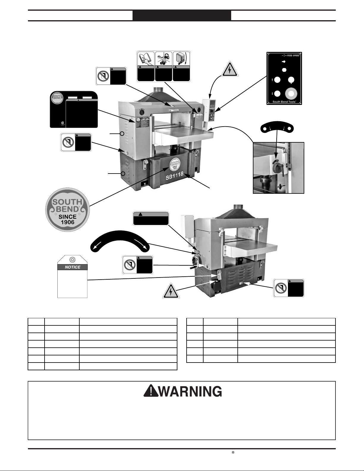
South Bend Tools
Model SB1118
Machine Labels
PARTS
For Machines Mfd. Since 10/21
SINCE
1906
Power Requirements: 220V/440V,
3-Phase, 60 Hz
Prewired Voltage: 220V
Main Motor: 15 HP
Full-Load Current Rating: 45A @ 220V,
26.5A @ 440V
Main Motor Speed: 3420 RPM
Cutterhead Speed: 4900 FPM
Cutterhead: Helical w/Indexable Inserts
Number of Replacement Inserts: 174
Feed Rate: 10–30 FPM
Max. Depth of Cut at Full Width: 1/8"
Max. Depth of Cut up to 6" Wide: 1/4"
Max. Cutting Width: 25"
Min. Stock Length: 10"
Min. Stock Thickness: 1/4"
Max. Stock Thickness: 9"
Weight: 1870 lbs.
Made in Taiwan to South Bend Specifications
406
Wiring motor out of phase
may result in machine
damage. After power
connection, if cutterhead
or table moves in wrong
direction, immediately
press emergency STOP
button, disconnect power,
then switch R and T wires
at power feed terminals.
406
413
MODEL SB1118
25" EXTREME SERIES PLANER
Serial No MFG Date
!
WARNING!
To reduce the risk of serious injury while using this machine:
1. Read and understand owner’s manual before operating.
2. Always wear approved safety glasses and respirator.
3. Disconnect power before changing inserts, removing parts, or doing
maintenance, service, or adjustments.
4. Properly ground machine—connect to permanently grounded metal
wiring system or an equipment-grounding conductor.
5. Do not wear loose clothing, gloves, jewelry, or other items that can get
entangled. Tie back long hair and roll up sleeves.
6. Ensure machine is correctly set up before starting.
7. Do not plane two boards of varying thickness a t the same time.
8. Never plane material smaller than 10" long, 3/4" wide, or 1/4" thick.
9. Do not allow hands or clothing to get pulled into cutting area while
feeding workpiece.
10. Stand clear of board ends during cutting operation.
11. Do not plane boards with cracks, loose knots, or other defects.
12. Inserts are sharp! Use extreme caution when changing/adjusting.
13. Never reach into cutting area while machine is running.
14. Keep fingers clear of pinch point between stock and table.
15. Do not operate when tired or under influence of drugs or alcohol.
16. Do not expose to rain or use in wet locations.
17. Prevent unauthorized use by children or untrained users; restrict access or
disable machine when unattended.
!
WARNING!
INJURY HAZARD
Keep cover closed
while machine is
operating.
Disconnect power
before removing or
servicing.
410
409
412
411
D
O
W
!
WARNING!
INJURY HAZARD
Keep cover closed
while machine is
operating.
Disconnect power
before removing or
servicing.
407
1
N
406
401
!
WARNING!
INJURY HAZARD
Do not use machine if
you have not read the
manual. Visit
southbendtools.com
or call 360-734-1540
to get a manual.
!
WARNING!
INJURY HAZARD
To reduce risk of shortand long-term injury,
wear eye, ear, and
lung protection when
using this machine.
!
WARNING!
DISCONNECT
POWER BEFORE
ADJUSTMENTS,
MAINTENANCE,
OR SERVICE.
402
10 FPM 30 FPM
TABLE UP
MAIN MOTOR
TABLE DOWN
403
ON
G
E
R
N
E
C
M
Y
E
STOP
404
0
.
0
0
5
"
405
SB1118
408
!
WARNING!
Disengage handwheel when using
table controls. Failure to comply could
result in serious personal injury!
=
v
1
e
/
3
R
2
"
U
P
!
WARNING!
INJURY HAZARD
Keep cover closed
while machine is
operating.
Disconnect power
before removing or
servicing.
402
406
!
INJURY HAZARD
Keep cover closed
while machine is
operating.
Disconnect power
before removing or
servicing.
WARNING!
REF PART # DE SCRIPTION REF PART # DE SCR IPTION
401 PSB1118401 COMBO SAFETY LAB EL 408 PSB1118408 DISENGAGE HANDWHEEL LABEL
402 PSB1118402 ELECTRICITY LABEL 40 9 PSB1118409 M OTOR PH ASE N OTICE
403 PSB1118403 CONTROL PAN EL LA BEL 410 PSB1118410 SOUTH BEND NAMEPLATE 203MM
404 PSB1118404 TABLE ROLLER LAB EL 411 PSB1118411 TOUCH -UP PAINT, SB DARK BLUE
405 PSB1118405 MODEL NUMBER LABEL 412 PSB1118412 TOUCH-UP PA IN T, SB LIGHT BLUE
406 PSB1118406 KEEP DOOR CLOSED LABEL 413 PSB1118413 MACHINE ID LABEL
407 PSB1118407 TABLE ELEVATION LABEL
The safety labels provided with your machine are used to make the operator aware of the
machine hazards and ways to prevent injury. The owner of this machine MUST maintain the
original location and readability of these safety labels. If any label is removed or becomes
unreadable, REPLACE that label before using the machine again. Contact South Bend Tools at
(360) 734-1540 or www.southbendtools.com to order new labels.
-80-
Page 89

WARRANTY
This quality product is warranted by South Bend Tools to the original buyer for 2 years from the
date of purchase. This warranty does not apply to consumable parts, or defects due to any kind of
misuse, abuse, negligence, accidents, repairs, alterations or lack of maintenance. We do not reimburse
for third party repairs. In no event shall we be liable for death, injuries to persons or property, or for
incidental, contingent, special or consequential damages arising from the use of our products.
We do not warrant or represent that this machine complies with the provisions of any law, act,
code, regulation, or standard of any domestic or foreign government, industry, or authority. In no
event shall South Bend’s liability under this warranty exceed the original purchase price paid for
this machine. Any legal actions brought against South Bend Tools shall be tried in the State of
Washington, County of Whatcom.
This is the sole written warranty for this machine. Any and all warranties that may be implied by
law, including any merchantability or fitness, for any purpose, are hereby limited to the duration of
this warranty.
Thank you for your business and continued support.
To take advantage of this warranty, register at
can scan the QR code below to be automatically directed to our warranty registration page. Enter all
applicable information for the product.
Warranty
https://www.grizzly.com/forms/warranty, or you
WARRANT Y
southbendtools.com
Page 90

southbendtools.com
Printed In Taiwan #MN22172
 Loading...