

Page 1
READ THIS FIRST
MODEL SB1100/SB1101
***IMPORTANT UPDATE***
SINCE
1906
Applies to Models Mfd. Since 01/22
and Owner’s Manual Revised 05/21
The following change was made to this machine since the owner’s manual was printed:
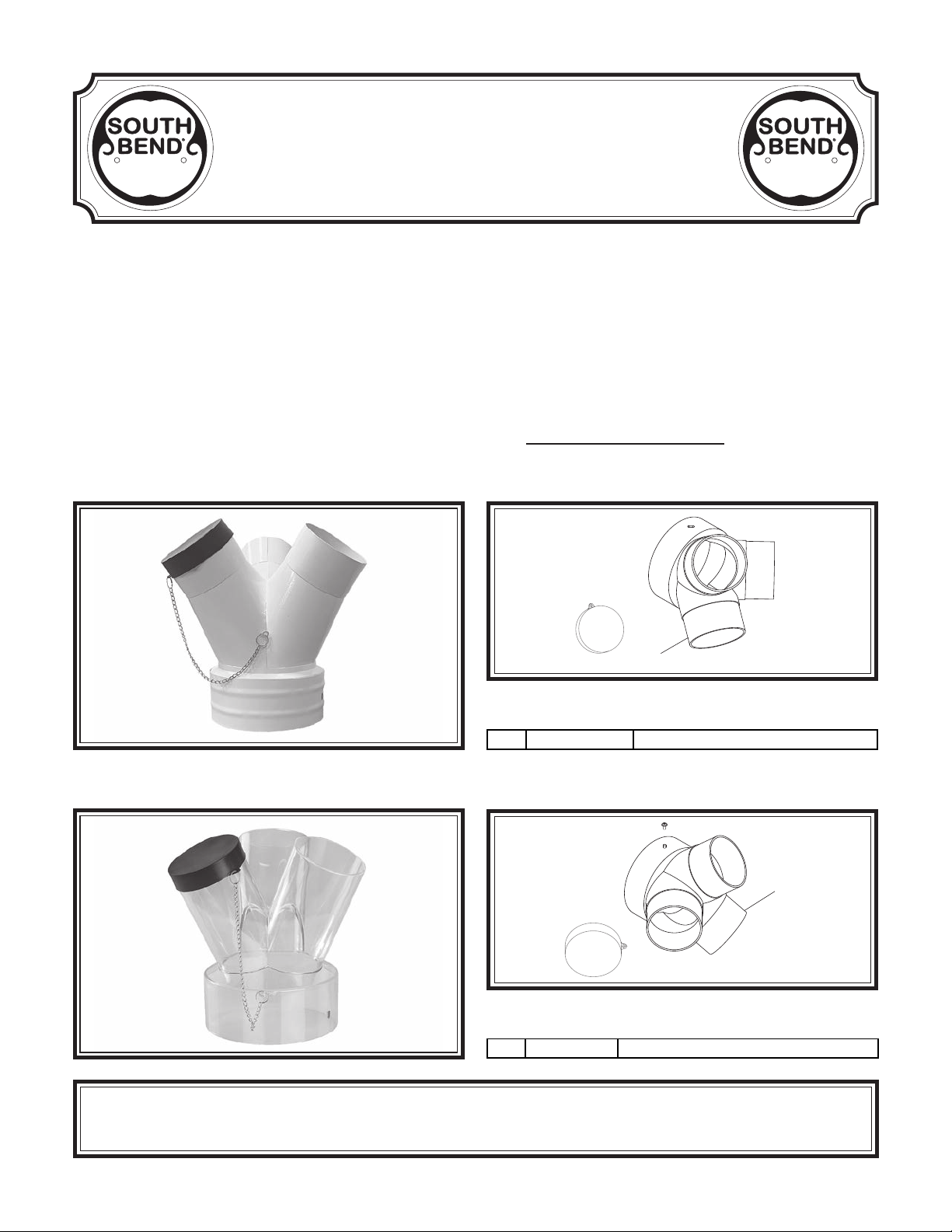
• The inlet adapter has changed.
Aside from this information, all other content in the owner’s manual applies and MUST be read and
understood for your own safety. IMPORTANT: Keep this update with the owner’s manual for
future reference.
If you have any further questions about this manual update or the changes made to the machine,
contact our Technical Support at (360) 734-1540 or email www.southbendtools.com.
SINCE
1906
Old Inlet Adapter
New Inlet Adapter
SB1100 Revised Parts
4V2
REF PART # DE SCRIPTION
4V2 PSB1100004V2 INLET ADAPTER 6" X 4" X 3 (PC) V2.01.22
SB1101 Revised Parts
14V2
REF PART # DE SCRIPTION
14V2 PSB1101014V2 INLET ADAPTER 7" X 4" X 3 (PC) V2. 01 .22
Copyright © September, 2022 by South Bend Tools
WARNING: No portion of this manual may be reproduced without written approval.
#JM22435 Printed in Taiwan
Page 2
SINGLE-STAGE DUST COLLECTORS
MODELS SB1100 & SB1101
OWNER'S MANUAL
®
South Bend Tools
A Tradition of Excellence
© November, 2020 - Revised May, 2021 (AI) For Machines Mfd. Since 05/21 (V2.05.21)
Page 3

We stand behind our machines. If you have any service questions, parts requests or general questions
about your purchase, feel free to contact us.
South Bend Tools
P.O. Box 2027
Bellingham, WA 98227
Phone: (360) 734-1540
Fax: (360) 676-1075 (International)
Fax: (360) 734-1639 (USA Only)
Email: [email protected]
For your convenience, any updates to this manual will be available to download free of charge
www.southbendtools.com
Scope of Manual
This manual helps the reader understand the machine, how to prepare it for operation, how to control
it during operation, and how to keep it in good working condition. We assume the reader has a basic
understanding of how to operate this type of machine, but that the reader is not familiar with the
controls and adjustments of this specific model. As with all machinery of this nature, learning the
nuances of operation is a process that happens through training and experience. If you are not an
experienced operator of this type of machinery, read through this entire manual, then learn more
from an experienced operator, schooling, or research before attempting operations. Following this
advice will help you avoid serious personal injury and get the best results from your work.
We've made every effort to be accurate when documenting this machine. However, errors sometimes
happen or the machine design changes after the documentation process—so
exactly match your machine.
contact our
We highly value customer feedback on our manuals. If you have a moment, please share your
experience using this manual. What did you like about it? Is there anything you would change to
make it better? Did it meet your expectations for clarity, professionalism, and ease-of-use?
South Bend Tools
C
P.O. Box 2027
Bellingham, WA 98227
Email: [email protected]
Manual Feedback
If a difference between the manual and machine leaves you in doubt,
customer service for clarification.
the manual may not
/O Technical Documentation Manager
Updates
through our website at:
Customer Service
Page 4

Table of Contents
INTRODUCTION
Identification
Description of Controls & Components
Product Specifications
SAFETY
Understanding Risks of Machinery
Basic Machine Safety
Additional Dust Collector Safety
PREPARATION
Preparation Overview
Required for Setup
Power Supply Requirements
Unpacking
SB1100 Inventory
SB1101 Inventory
Hardware Recognition Chart
Location
Assembly
Test Run
SYSTEM DESIGN
General
Duct Material
System Design
System Grounding
................................................................................ 7
.............................................................. 16
............................................................17
............................................................. 22
............................................................... 23
............................................................... 2
........................................................ 2
.........................................4
.................... 7
..........................................7
........................9
.............................................................. 10
........................................10
............................................. 10
............................. 11
..........................................................13
..............................................13
..............................................14
............................ 15
......................................................... 23
..................................................... 23
....................................................25
.............................................31
..............3
OPERATION .................................................................... 32
Operation Overview
ACCESSORIES
MAINTENANCE
Maintenance Schedule
Cleaning Canister Filter....................................36
Removing/Replacing Collection Bag
Removing/Replacing Canister Filter
SERVICE........................................................................... 41
Pairing Remote Control & Receiver
TROUBLESHOOTING
ELECTRICAL
Electrical Safety Instructions
SB1100 Wiring Diagram
SB1100 Electrical Component Pictures
SB1101 Wiring Diagram
SB1101 Electrical Component Pictures
PARTS................................................................................51
SB1100 Main
SB1101 Main
Canister Filter....................................................55
Machine Labels
WARRANTY
................................................................... 44
...................................................... 51
...................................................... 53
..................................................................... 57
........................................... 32
.............................................................. 33
.............................................................36
.......................................36
.................37
................37
..................41
................................................. 42
...........................44
...................................45
............46
...................................48
............49
.................................................. 56
Page 5
South Bend Tools
Model SB1100 & SB1101
INTRODUCTIOn
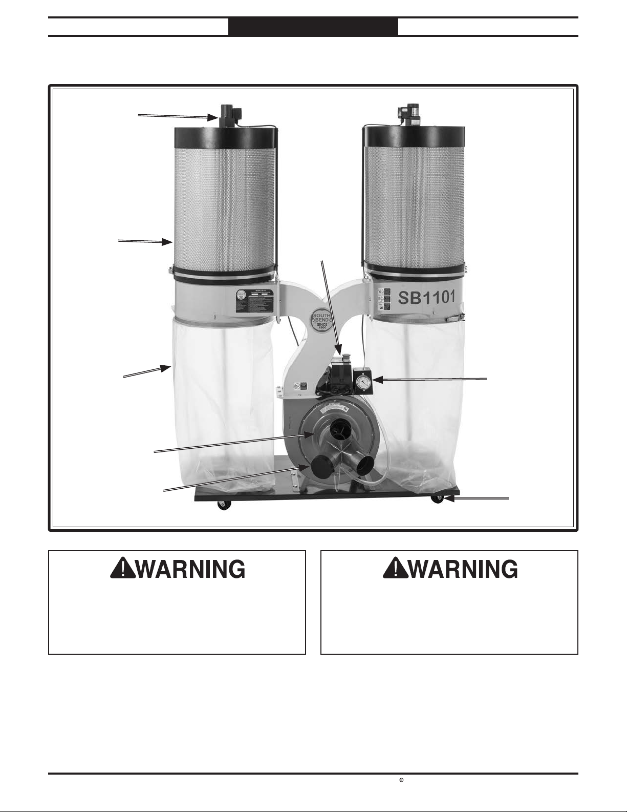
Identification
Filter BrushFilter Brush
MotorMotor
INTRODUCTION
For Machines Mfd. Since 05/21
Canister Canister
FilterFilter
CollectionCollection
BagBag
Inlet Inlet
PortPort
InletInlet
AdapterAdapter
SwitchSwitch
BoxBox
Pressure Pressure
GaugeGauge
SwivelSwivel
CasterCaster
Serious personal injury could occur if
you connect the machine to power before
completing the setup process. DO NOT
connect power until instructed to do so later
in this manual.
-2-
Untrained users have an increased risk
of seriously injuring themselves with this
machine. Do not operate this machine until
you have understood this entire manual and
received proper training.
Page 6
South Bend Tools
For Machines Mfd. Since 05/21 Model SB1100 & SB1101
INTRODUCTION
Description of Controls & Components
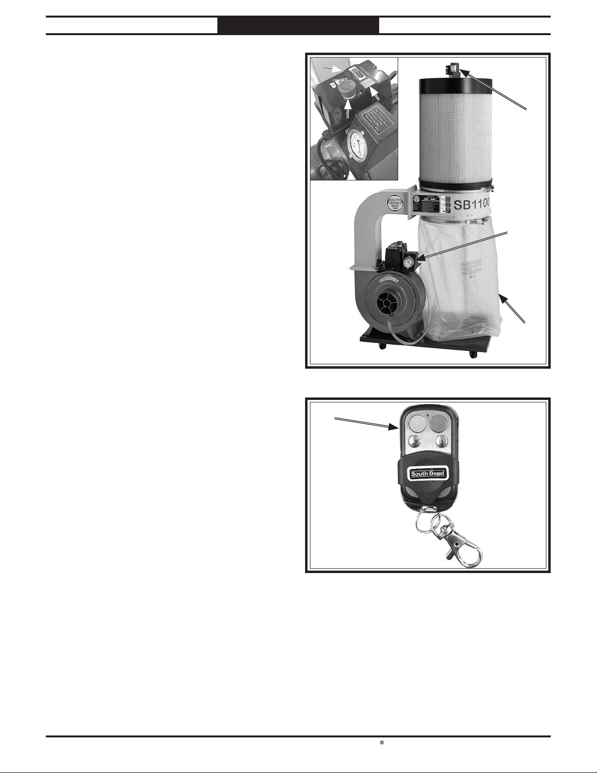
Refer to Figures 1-2 and the following
descriptions to become familiar with the basic
controls and components used to operate this
machine.
A. Switch Box: Controls motor operation with a
thermally protected magnetic switch. Houses
an RF receiver for remote control operation.
B. Start Button: Turns machine ON.
C. Emergency Stop Button: Turns machine
OFF and prevents it from starting. Turn
button clockwise to reset.
D. Filter Brush Motor: Turns ON for
approximately 90 seconds after main motor
is turned OFF. Knocks dust cake off filter
pleats, cleaning filter and maintaining air
flow. Filter brush motor run time can be
changed at timer inside switch box (refer to
Wiring on Page 44).
AA
BB
CC
Figure Figure 1. SB1100 & SB1101 components.. SB1100 & SB1101 components.
DD
EE
FF
E. Pressure Gauge: Displays vacuum pressure,
indicating when filter and collection bags
need to be cleaned or replaced. Clean filter
when operating pressure drops below
200mmAq. If operating pressure reaches
150mmAq and cleaning does not improve
performance, replace the filter.
F. Collection Bag: Collects fine dust particles
from filter.
G. Remote Control: Green button turns motor
ON. Red button turns motor OFF. Requires
a 12V, type A27 battery.
Note: The remote control operates on radio
frequency and has a 75-ft. range. It does not
need to be aimed at the switch box to operate.
GG
Figure Figure 2. SB1100 & SB1101 remote control.
-3-
Page 7
South Bend Tools
Model SB1100 & SB1101
INTRODUCTION
For Machines Mfd. Since 05/21
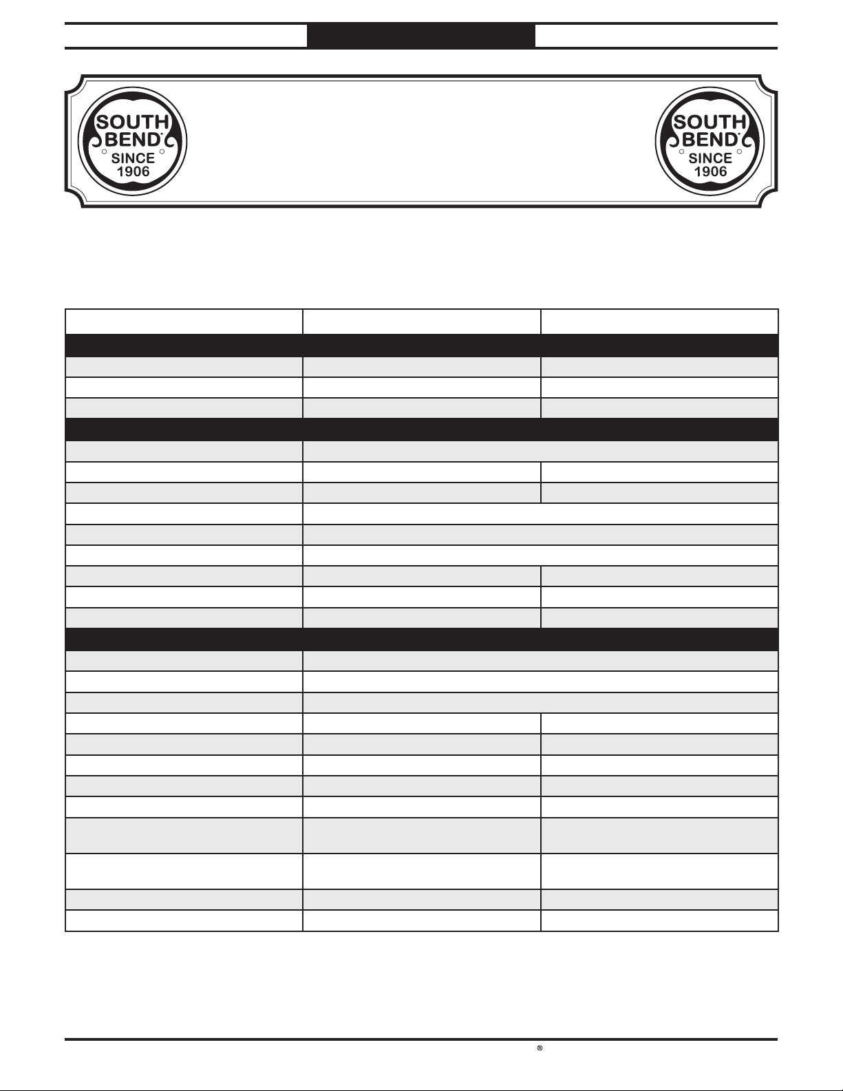
Product Specifications
Product Specifications
P.O. Box 2027, Bellingham, WA 98227 U.S.A.
PHONE: (360) 734-1540 •
www.southbendtools.com
Model SB1100 & SB1101
Cyclone Dust Collectors
Model Number SB1100 SB1101
Product Dimensions
Weight 157 lbs 208 lbs.
Width x Depth x Height 39 x 31-1/2 x 76 in. 58 x 31-1/2 x 76 in.
Footprint (Length/Width) 33-1/2 x 21-1/2 in. 49-1/2 x 21-1/2 in.
Shipping Dimensions
Carton #1 Type Cardboard Box
Weight 131 lbs. 169 lbs.
Length x Width x Height 23 x 36 x 23 in. 52 x 23 x 23 in.
Carton #2 Type Cardboard Box (Canister Filter)
Weight 34 lbs
Length x Width x Height 22 x 22 x 32 in.
Carton #3 Type N/A Cardboard Box (Canister Filter 2)
Weight N/A 34 lbs
Length x Width x Height N/A 22 x 22 x 32 in.
Operation
Dust Collector Type Single-Stage
Approved Dust Types Wood
Filter Type Pleated Cartridge
Airflow Performance 1103 CFM @ 3.5 in. SP 1429 CFM @ 3.2 in. SP
Max Static Pressure (at 0 CFM) 11.95 in. 12 in.
Main Inlet Size 6 in. 7 in.
Number of Adapter Inlets 3 3
Adapter Inlet Size 4 in. 4 in.
Machine Collection Capacity at One
Time
Maximum Material Collection
Capacity
Filtration Rating 1 Micron 1 Micron
Filter Surface Area 80 sq. ft. 160 sq. ft.
33-1/2 Gallons 67 Gallons
© South Bend Tools
3 3
-4-
Page 8
South Bend Tools
For Machines Mfd. Since 05/21 Model SB1100 & SB1101
INTRODUCTION
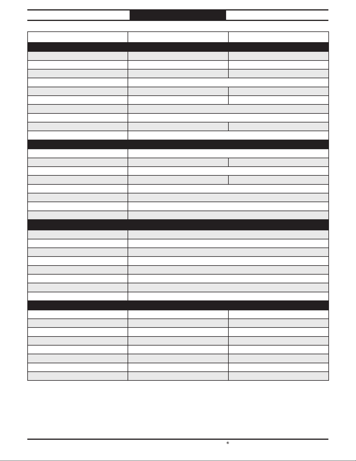
Model Number SB1100 SB1101
Electrical
Power Requirement 220V, Single-Phase, 60 Hz 240V, Single-Phase, 60 Hz
Full-Load Current Rating 9A 12A
Minimum Circuit Size 15A 20A
Connection Type Cord & Plug
Power Cord Included Yes Yes
Power Cord Length 65 in. 64 in.
Power Cord Gauge 14 AWG
Plug Included Yes
Included Plug Type 6-15 6-20
Switch Type Remote Control Magnetic Switch w/Overload Protection
Main Motor
Type TEFC Capacitor-Start Induction
Horsepower 2 HP 3 HP
Phase Single-Phase
Amps 9A 12A
Speed 3450 RPM
Power Transfer Direct
Bearings Shielded & Permanently Lubricated
Centrifugal Switch/Contacts Type External
Filter Brush Motor
Type TENV Induction
Horsepower 6W
Phase Single-Phase
Amps 0.15A
Speed 1600 RPM
Power Transfer Direct
Bearings Shielded & Permanently Lubricated
Centrifugal Switch/Contacts Type External
Filter Brush Motor 2
Type N/A TENV Induction
Horsepower N/A 6W
Phase N/A Single-Phase
Amps N/A 0.15A
Speed N/A 1600 RPM
Power Transfer N/A Direct
Bearings N/A Shielded & Permanently Lubricated
Centrifugal Switch/Contacts Type N/A External
-5-
Page 9
South Bend Tools
Model SB1100 & SB1101
INTRODUCTION
For Machines Mfd. Since 05/21
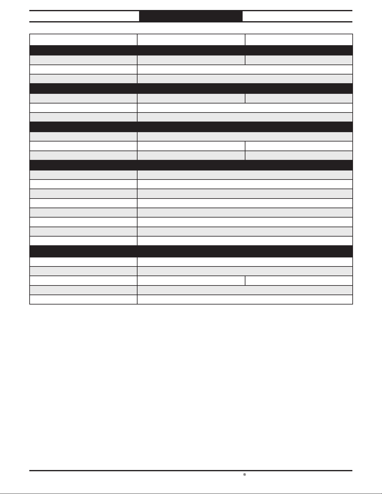
Model Number SB1100 SB1101
Bag Information
Number of Filter Bags 1 2
Filter Bag Diameter 19-1/2 in.
Filter Bag Length 37 in.
Canister Information
Number of Canister Filters 1 2
Canister Filter Diameter 19-5/8 in.
Canister Filter Length 29 in.
Impeller Information
Impeller Type Radial Fan
Impeller Size 12-3/4 in. 12-3/4 in.
Impeller Blade Thickness 1/8 in. 1/8 in.
Construction
Filter Collection Bag Clear Plastic
Canister Spun Bond Polyester
Base Steel
Caster Plastic
Impeller Aluminum
Paint Type/Finish Powder Coated
Blower Housing Steel
Body Steel
Manufacturer Specifications
Country of Origin Taiwan
Warranty 1 Year
Approximate. Assembly & Setup Time 45 Minutes 1 Hour
Serial Number Location ID Label
Sound Rating N/A
-6-
Page 10
South Bend Tools
For Machines Mfd. Since 05/21 Model SB1100 & SB1101
Operating all machinery and machining equipment can be dangerous or relatively safe depending
on how it is installed and maintained, and the operator's experience, common sense, risk awareness,
working conditions, and use of personal protective equipment (safety glasses, respirators, etc.).
The owner of this machinery or equipment is ultimately responsible for its safe use. This
responsibility includes proper installation in a safe environment, personnel training and usage
authorization, regular inspection and maintenance, manual availability and comprehension,
application of safety devices, integrity of cutting tools or accessories, and the usage of approved
personal protective equipment by all operators and bystanders.
The manufacturer of this machinery or equipment will not be held liable for injury or property
damage from negligence, improper training, machine modifications, or misuse. Failure to read,
understand, and follow the manual and safety labels may result in serious personal injury, including
amputation, broken bones, electrocution, or death.
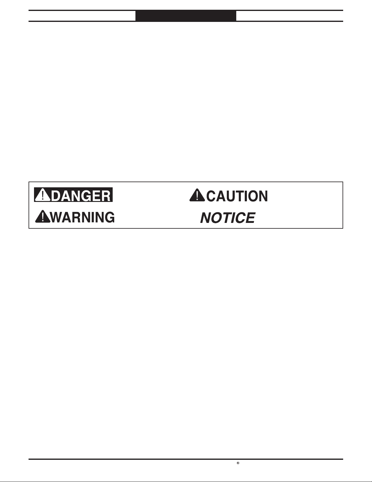
The signals used in this manual to identify hazard levels are as follows:
Owner’s Manual: All machinery and machining
Trained/Supervised Operators Only: Untrained
SAFETY
SAFETY
Understanding Risks of Machinery
Death or catastrophic
harm WILL occur.
Death or catastrophic
harm COULD occur.
Moderate injury or fire
MAY occur.
Machine or property
damage may occur.
Basic Machine Safety
equipment presents serious injury hazards
to untrained users. To reduce the risk of
injury, anyone who uses THIS item MUST
read and understand this entire manual
before starting.
Personal Protective Equipment:
servicing this item may expose the user
to flying debris, dust, smoke, dangerous
chemicals, or loud noises. These hazards
can result in eye injury, blindness, longterm respiratory damage, poisoning,
cancer, reproductive harm or hearing loss.
Reduce your risks from these hazards
by wearing approved eye protection,
respirator, gloves, or hearing protection.
Operating or
users can seriously injure themselves
or bystanders. Only allow trained and
properly supervised personnel to operate
this item. Make sure safe operation
instructions are clearly understood. If
electrically powered, use padlocks and
master switches, and remove start switch
keys to prevent unauthorized use or
accidental starting.
Guards/Covers:
moving parts during operation may cause
severe entanglement, impact, cutting,
or crushing injuries. Reduce this risk by
keeping any included guards/covers/doors
installed, fully functional, and positioned
for maximum protection.
Accidental contact with
-7-
Page 11

South Bend Tools
Model SB1100 & SB1101
Entanglement: Loose clothing, gloves, neckties,
rotate.
Chuck Keys or Adjusting Tools:
Tools used to
our Technical Support for assistance.
SAFETY
For Machines Mfd. Since 05/21
jewelry or long hair may get caught in
moving parts, causing entanglement,
amputation, crushing, or strangulation.
Reduce this risk by removing/securing
these items so they cannot contact moving
parts.
Mental Alertness: Operating this item with
reduced mental alertness increases the
risk of accidental injury. Do not let a
temporary influence or distraction lead to a
permanent disability! Never operate when
under the influence of drugs/alcohol, when
tired, or otherwise distracted.
Safe Environment:
powered equipment in a wet environment
may result in electrocution; operating near
highly flammable materials may result in a
fire or explosion. Only operate this item in
a dry location that is free from flammable
materials.
Electrical Connection: With electically powered
equipment, improper connections to the
power source may result in electrocution
or fire. Always adhere to all electrical
requirements and applicable codes when
connecting to the power source. Have all
work inspected by a qualified electrician to
minimize risk.
Disconnect Power: Adjusting or servicing
electrically powered equipment while it
is connected to the power source greatly
increases the risk of injury from accidental
startup. Always disconnect power
BEFORE any service or adjustments,
including changing blades or other tooling.
Operating electrically
adjust spindles, chucks, or any moving/
rotating parts will become dangerous
projectiles if left in place when the machine
is started. Reduce this risk by developing
the habit of always removing these tools
immediately after using them.
Work Area:
the risks of accidental injury. Only operate
this item in a clean, non-glaring, and welllighted work area.
Properly Functioning Equipment:
maintained, damaged, or malfunctioning
equipment has higher risks of causing
serious personal injury compared to
those that are properly maintained.
To reduce this risk, always maintain
this item to the highest standards and
promptly repair/service a damaged or
malfunctioning component. Always follow
the maintenance instructions included in
this documentation.
Unattended Operation:
equipment that is left unattended while
running cannot be controlled and is
dangerous to bystanders. Always turn the
power OFF before walking away.
Health Hazards: Certain cutting fluids and
lubricants, or dust/smoke created when
cutting, may contain chemicals known to
the State of California to cause cancer,
respiratory problems, birth defects,
or other reproductive harm. Minimize
exposure to these chemicals by wearing
approved personal protective equipment
and operating in a well ventilated area.
Clutter and dark shadows increase
Poorly
Electrically powered
Secure Workpiece/Tooling:
cutting tools, or rotating spindles can
become dangerous projectiles if not
secured or if they hit another object during
operation. Reduce the risk of this hazard
by verifying that all fastening devices are
properly secured and items attached to
spindles have enough clearance to safely
-8-
Loose workpieces,
Difficult Operations:
operations with which you are unfamiliar
increases the risk of injury. If you
experience difficulties performing the
intended operation, STOP! Seek an
alternative method to accomplish the
same task, ask a qualified expert how the
operation should be performed, or contact
Attempting difficult
Page 12

South Bend Tools
For Machines Mfd. Since 05/21 Model SB1100 & SB1101
overhead lights, heaters, electrical panels, or
disconnect from power, and wait for impeller
exposed to in case of an allergic reaction.
Intended Use.
Wear a Respirator.
Impeller Hazards.
Hazardous Dust
Emptying Dust.
Operating Location.
will reduce life of machine.
SAFETY
Additional Dust Collector Safety
Long-term respiratory damage can occur from using dust collectors without proper use of a
respirator. Fire or explosions can result in smoke inhalation, serious burns, or death—if machine
is used to collect incorrect materials, is operated near potential explosion sources, or ducting is
improperly grounded. Entanglement, amputation, or death can occur if hair, clothing, or fi ngers
are pulled into the inlet. To reduce the risk of these hazards, operator and bystanders MUST
completely heed the hazards and warnings below.
can result in serious inhalation hazards, fire,
explosions, or machine damage. This machine
is ONLY designed to collect wood dust and
chips from woodworking machines. DO NOT
use it to collect silica, polyurethane, toxic
fumes, metal dust or shavings, lead paint,
drywall, asbestos, biohazards, explosive dusts,
flammable or combustible liquids or fumes,
nor burning or smoking material.
be caught in filter will be blown into ambient
air. Always wear a NIOSH-approved
respirator during operation and for a short
time after to reduce your risk of permanent
respiratory damage. Never collect dust from
any hazardous material.
or contact with impeller, DO NOT place hands,
hair, clothing, or tools in or near open dust
collection inlet during operation, and keep
small animals and children away. The powerful
suction could easily pull them into impeller.
using machinery may cause cancer, birth
defects, or long-term respiratory damage.
Be aware of dust hazards associated with
each workpiece material, and always wear a
NIOSH-approved respirator.
wear respirator and safety glasses. Empty
dust away from ignition sources and into
approved container.
exposure to fine dust, locate permanently
installed dust collectors away from working
area or in another room. DO NOT place dust
collector where it can be exposed to rain or
moisture, which creates a shock hazard and
Collecting the wrong materials
Fine dust that is too small to
To reduce risk of entanglement
. Dust exposure created while
When emptying bag or drum,
To reduce respiratory
Power Disconnect. Turn machine OFF,
disconnect from power supply, and
allow impeller to completely stop before
leaving machine unattended, or doing any
maintenance or service.
Regular Cleaning. To reduce risk of starting
a fire, regularly check/empty collection
bags or drum to avoid buildup of fine dust,
which can increase risk of fire. Regularly
clean surrounding area where machine
is operated—excessive dust buildup on
other heat sources will increase risk of fire.
Suspended Dust Particles. To reduce risk of
death or injury caused by explosions or fires,
DO NOT operate in areas where these risks
are high, including spaces near pilot lights,
open flames, or other ignition sources.
Avoiding Sparks. To reduce risk of fire, avoid
collecting any metal objects or stones. These
can possibly produce sparks when they
strike impeller, which can smolder in wood
dust for a long time before a fire is detected.
If you accidentally cut into wood containing
metal, immediately turn OFF dust collector,
to stop. Then empty bag or drum into
approved airtight metal container.
Fire Suppression. Only operate dust collector
in locations that contain fire suppression
system or have fire extinguisher nearby.
Static Electricity. To reduce risk of fire or
explosions caused by sparks from static
electricity, ground all ducting using
grounding wire.
Dust Allergies. Dust from certain woods will
cause an allergic reaction. Make sure you
know what type of wood dust you will be
-9-
Page 13
South Bend Tools
Model SB1100 & SB1101
PREPARATION
PREPARATION
For Machines Mfd. Since 05/21
Preparation Overview Required for Setup
The purpose of the preparation section is to help
you prepare your machine for operation. The list
below outlines the basic process. Specific steps
for each of these points will be covered in detail
later in this section.
The typical preparation process is as follows:
1. Unpack the machine and inventory the
contents of the box/crate.
Clean the machine and its components.
2.
3. Identify an acceptable location for the
machine and move it to that location.
Assemble the loose components and make
4.
any necessary adjustments or inspections to
ensure the machine is ready for operation.
Connect the machine to the power source.
5.
6. Test run the machine to make sure it
functions properly and is ready for operation.
Like all machinery there is potential danger
when operating this machine. Accidents are
frequently caused by lack of familiarity or
failure to pay attention. Use this machine with
respect and caution to decrease the risk of
operator injury. If normal safety precautions are
overlooked or ignored, serious personal injury
may occur.
The items listed below are required to
successfully set up and prepare this machine for
operation.
For Power Connection
• A power source that meets the minimum
circuit requirements for this machine. (Refer
to the Power Supply Requirements
section for details.)
• A qualified electrician to ensure a safe and
code-compliant connection to the power
source.
For Assembly
• An Assistant
• Safety Glasses (for each person)
• Phillips Screwdriver #2
• Wrench or Socket 1⁄2"
No list of safety guidelines can be complete.
Every shop environment is different. Always
consider safety first, as it applies to your individual working conditions. Use this and other
machinery with caution and respect. Failure to
do so may result in serious personal injury or
property damage.
-10-
Page 14
South Bend Tools
For Machines Mfd. Since 05/21 Model SB1100 & SB1101
Before installing the machine, consider the
availability and proximity of the required power
supply circuit. If an existing circuit does not meet
the requirements for this machine, a new circuit
must be installed.
To minimize the risk of electrocution, fire,
or equipment damage, installation work and
electrical wiring must be done by a
or qualified service personnel
applicable electrical codes and safety standards.
The full-load current rating is the amperage
a machine draws at 100% of the rated output
power. On machines with multiple motors, this is
the amperage drawn by the largest motor or sum
of all motors and electrical devices that might
operate at one time during normal operations.
The full-load current is not the maximum
amount of amps that the machine will draw. If
the machine is overloaded, it will draw additional
amps beyond the full-load rating.
If the machine is overloaded for a sufficient
length of time, damage, overheating, or fire may
result—especially if connected to an undersized
circuit. To reduce the risk of these hazards,
avoid overloading the machine during operation
and make sure it is connected to a power supply
circuit that meets the requirements in the
following section.
Note: The circuit requirements in this manual
are for
machine will be running at a time. If this
machine will be connected to a shared circuit
where multiple machines will be running at
the same time, consult a qualified electrician to
ensure the circuit is properly sized.
A power supply circuit includes all electrical
equipment between the main breaker box or fuse
panel in your building and the incoming power
connections inside the machine. This circuit
must be safely sized to handle the full-load
current that may be drawn from the machine for
an extended period of time. (If this machine is
connected to a circuit protected by fuses, use a
time delay fuse marked D.)
This machine must be grounded! In the event
of
grounding provides a path of least resistance
for electric current
electric shock.
Improper connection of the equipment-grounding
wire can result in a risk of electric shock. The
wire with green insulation (with or without
yellow stripes) is the equipment-grounding wire.
If repair or replacement of the power cord or
plug is necessary, do not connect the equipmentgrounding wire to a live (current carrying)
terminal.
Check with an electrician or qualified service
personnel if you do not understand these
grounding requirements, or if you are in doubt
about whether the tool is properly grounded.
If you ever notice that a cord or plug is
damaged or worn, disconnect it from power, and
immediately replace it with a new one.
PREPARATION
Power Supply Requirements
Availability
in accordance with
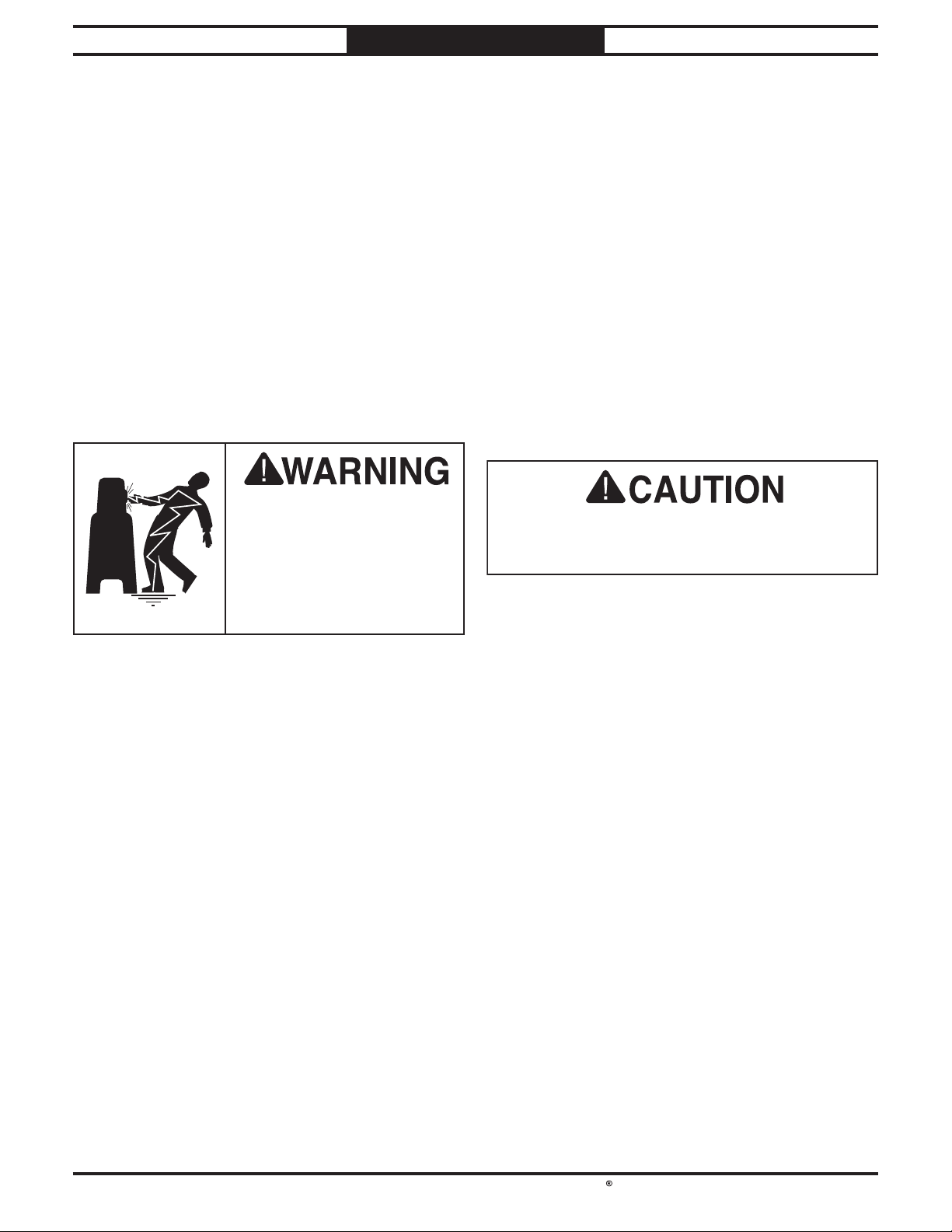
Electrocution or fire may
occur if machine is not
correctly grounded and
attached to the power
supply. Use a qualified
electrician to ensure a safe
power connection.
Circuit Information
a dedicated circuit—where only one
n electrician
For your own safety and protection of property,
consult an electrician if you are unsure about
wiring practices or applicable electrical codes.
Grounding Requirements
Full-Load Current Rating
SB1100 at 220V ....................................... 9 Amps
SB1101 at 240V
..................................... 12 Amps
certain types of malfunctions or breakdowns,
in order to reduce the risk of
-11-
Page 15
South Bend Tools
Model SB1100 & SB1101
This machine is equipped with a power cord
that has
grounding plug
The plug
receptacle (outlet)
grounded in accordance with all local codes and
ordinances.
This machine is equipped with a power cord
that has
grounding plug
The plug
receptacle (outlet)
grounded in accordance with all local codes and
ordinances.
We do not recommend using an extension cord
with this machine. If you must use one, only
use it if absolutely necessary and only on a
temporary basis.
Extension cords cause voltage drop, which may
damage electrical components and shorten motor
life. Voltage drop increases as the extension cord
size gets longer and the gauge size gets smaller
(higher gauge numbers indicate smaller sizes).
Any extension cord used with this machine
must contain a ground wire, match the required
plug and receptacle listed in the
Requirements
meet the following requirements:
This machine is prewired to operate on a power
supply circuit that has a verified ground and
meets the following requirements:
This machine is prewired to operate on a power
supply circuit that has a verified ground and
meets the following requirements:
PREPARATION
For Machines Mfd. Since 05/21
SB1100 Circuit Information SB1101 Circuit Information
Nominal Voltage ......................................... 220V
Cycle
Phase
Circuit Rating....................................... 15 Amps
Plug/Receptacle (included)
.............................................................60 Hz
..............................................Single-Phase
...........NEMA 6-15
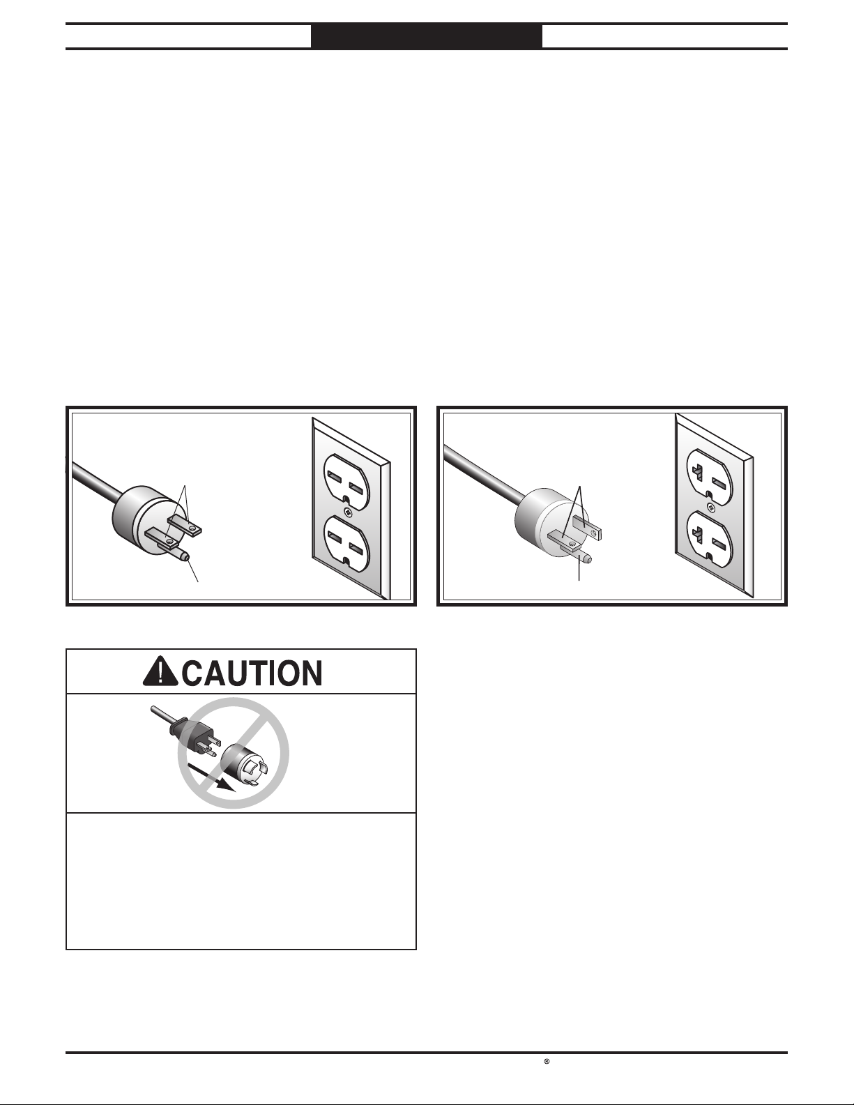
an equipment-grounding wire and a
(similar to the figure below).
must only be inserted into a matching
that is properly installed and
GROUNDED
6-15 RECEPTACLE
Current Carrying Prongs
6-15 PLUG
Nominal Voltage ......................................... 240V
Cycle
Phase
Circuit Rating....................................... 20 Amps
Plug/Receptacle (included)
.............................................................60 Hz
..............................................Single-Phase
...........NEMA 6-20
an equipment-grounding wire and a
(similar to the figure below).
must only be inserted into a matching
that is properly installed and
GROUNDED
6-20 RECEPTACLE
Current Carrying Prongs
6-20 PLUG
Grounding Prong
Figure Figure 3. NEMA 6-15 plug and receptacle.. NEMA 6-15 plug and receptacle.
No adapter should be used with plug. If
plug does not fit available receptacle, or if
machine must be reconnected for use on a
different type of circuit, reconnection must
be performed by an electrician or qualified
service personnel, and it must comply with all
local codes and ordinances.
-12-
Grounding Prong
Figure Figure 4. NEMA 6-20 plug and receptacle.. NEMA 6-20 plug and receptacle.
Extension Cords
Circuit
for the applicable voltage, and
SB1100 .............................. 14 AWG, 50 ft or less
SB1101
.............................. 12 AWG, 50 ft or less
Page 16
South Bend Tools
For Machines Mfd. Since 05/21 Model SB1100 & SB1101
This item was carefully packaged to prevent
damage during transport. If you discover any
damage, please immediately call Customer
Service at
need to file a freight claim, so save the containers
and all packing materials for possible inspection
by the carrier or its agent.
PREPARATION
Unpacking
(360) 734-1540 for advice. You may
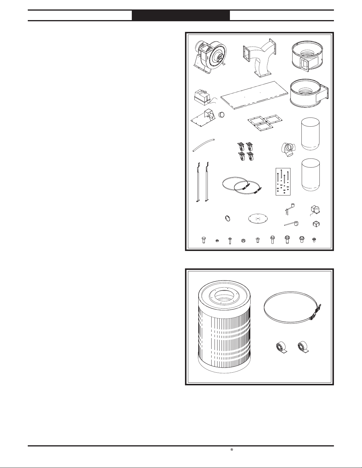
SB1100 Inventory
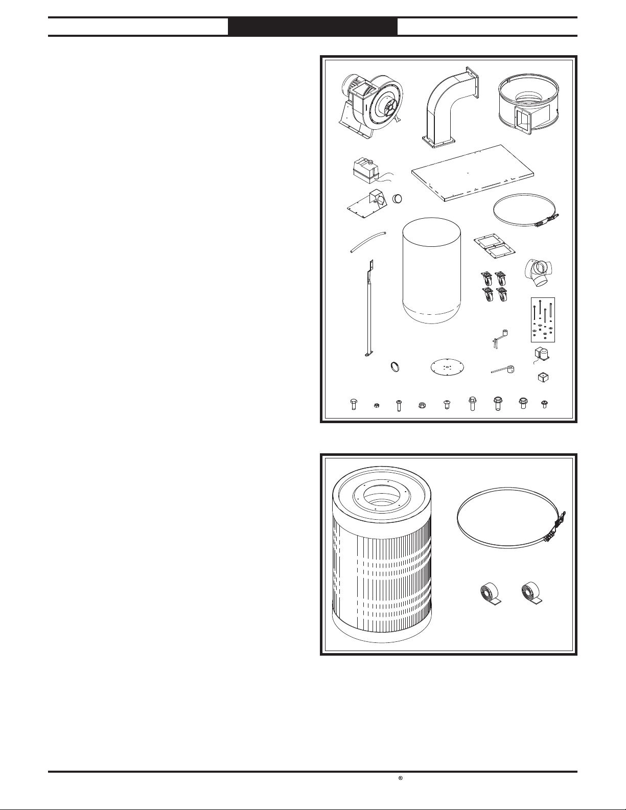
Main Inventory (Figure 5) Qty
A. Motor/Impeller Assembly .............................. 1
Outlet Tube ....................................................1
B.
Collector ..........................................................1
C.
Switch Box ...................................................... 1
D.
Base ................................................................1
E.
Gauge Bracket ................................................ 1
F.
Pressure Gauge .............................................. 1
G.
Hose 1⁄2" ........................................................... 1
H.
Collection Bag ................................................ 1
I.
Square Gaskets ..............................................2
J.
K. Bag Clamp ...................................................... 1
Canister Support ............................................1
L.
Swivel Casters ................................................4
M.
Inlet Adapter .................................................. 1
N.
Upper Alignment Arm ................................... 1
O.
P. Filter Motor Hardware Bag ........................... 1
— Cap Screws M4-.7 x 60 .............................. 4
— Lock Washers 4mm ................................... 4
— Flat Washers 4mm .................................... 4
— Hex Nuts M4-.7 .........................................4
Q. Hose Clamps 3⁄4" .............................................2
R. Filter Cover ....................................................1
S. Lower Alignment Arm ................................... 1
T. Filter Brush Motor ......................................... 1
U. Gear Reducer .................................................. 1
V. Hex Bolts M6-1 x 16 ....................................... 2
W. Hex Nuts 10-24 ..............................................2
X. Phillips Head Screws 10-24 x 3⁄4" ...................2
Y. Flange Nuts 1⁄4"-20 .........................................2
Z. Button Head Cap Screws 1⁄4"-20 x 1⁄2" ............ 2
AA. Flange Bolts 1⁄4"-20 x 3⁄4" .................................6
AB. Flange Bolts 5⁄16"-18 x 1⁄2" .............................38
AC. Flange Bolts 5⁄16"-18 x 3⁄4" ...............................2
AD. Flange Screw 10-24 x 3⁄8" ...............................1
AA
DD
FF
HH
LL
QQ
VV
Figure Figure 6. SB1100 canister filter inventory.. SB1100 canister filter inventory.
Filter Box (Figure 6) Qty
AE. Canister Filter Assembly ............................... 1
Canister Clamp .............................................. 1
AF.
Foam Tape 5 x 42mm .................................... 1
AG.
AH. Foam Tape 5 x 20mm .................................... 1
XX
WW
Figure Figure 5. SB1100 main inventory.. SB1100 main inventory.
BB
EE
GG
KK
II
RR
ZZ
YY
AEAE
JJ
MM
OO
SS
AAAA ABAB
AGAG AHAH
PP
ACAC
CC
NN
TT
UU
ADAD
AFAF
-13 -
Page 17
South Bend Tools
Model SB1100 & SB1101
PREPARATION
For Machines Mfd. Since 05/21
SB1101 Inventory
Main Inventory (Figure 7) Qty
A. Motor/Impeller Assembly .............................. 1
Outlet Tube ....................................................1
B.
Right Collector ............................................... 1
C.
Switch Box ...................................................... 1
D.
E. Base ................................................................1
Left Collector .................................................. 1
F.
Gauge Bracket ................................................ 1
G.
Pressure Gauge .............................................. 1
H.
Square Gaskets .............................................. 3
I.
Hose 1⁄2" ........................................................... 1
J.
K. Swivel Casters ................................................ 4
Inlet Adapter .................................................. 1
L.
M. Collection Bags ............................................... 2
Canister Supports .......................................... 2
N.
Bag Clamps ....................................................2
O.
Filter Motor Hardware Bags ......................... 2
P.
— Cap Screws M4-.7 x 60 .............................. 8
— Lock Washers 4mm ................................... 8
— Flat Washers 4mm .................................... 8
— Hex Nuts M4-.7 .........................................8
Q. Hose Clamps 3⁄4" .............................................2
R. Filter Covers ...................................................2
S. Upper Alignment Arms ................................. 2
T. Filter Brush Motors ....................................... 2
U. Lower Alignment Arms ................................. 2
V. Gear Reducers ................................................ 2
W. Hex Bolts M6-1 x 16 ....................................... 4
X. Hex Nuts 10-24 .............................................. 2
Y. Phillips Head Screws 10-24 x 3⁄4" ...................2
Z. Flange Nuts 1⁄4"-20 .........................................2
AA. Button Head Cap Screws 1⁄4"-20 x 1⁄2" ............ 2
AB. Flange Bolts 1⁄4"-20 x 3⁄4" ...............................12
AC. Flange Bolts 5⁄16"-18 x 1⁄2" .............................48
AD. Flange Bolts 5⁄16"-18 x 3⁄4" ...............................4
AE. Flange Screw 10-24 x 3⁄8" ...............................1
Filter Box 1 (Figure 8) Qty
AF. Canister Filter Assembly ............................... 1
Canister Clamp .............................................. 1
AG.
Foam Tape 5 x 42mm .................................... 1
AH.
Foam Tape 5 x 20mm ....................................1
AI.
DD EE
GG
JJ
NN
WW
XX
Figure Figure 7. SB1101 main inventory.. SB1101 main inventory.
AA
HH
QQ
YY
BB
KK
OO
RR
ZZ AAAA
AFAF
II
PP
ABAB
AHAH
CC
FF
LL
MM
SS
UU
ACAC
ADAD
TT
VV
AEAE
AGAG
AIAI
Filter Box 2 (Figure 8
) Qty
AF. Canister Filter Assembly ............................... 1
Canister Clamp .............................................. 1
AG.
Foam Tape 5 x 42mm .................................... 1
AH.
Foam Tape 5 x 20mm ....................................1
AI.
-14-
Figure Figure 8. SB1101 canister filter inventory.. SB1101 canister filter inventory.
Page 18
South Bend Tools
For Machines Mfd. Since 05/21 Model SB1100 & SB1101
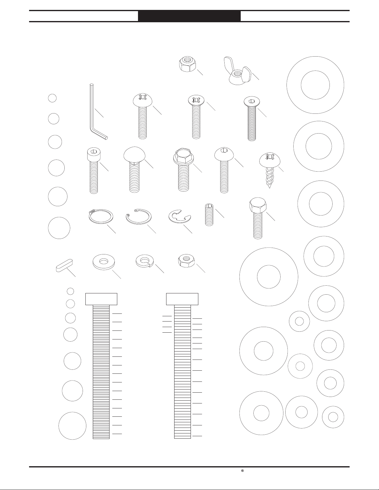
USE THIS CHART TO MATCH UP
Hardware Recognition Chart
PREPARATION
Hardware Recognition Chart
HARDWARE DURING THE INVENTORY
AND ASSEMBLY PROCESS.
#
10
1
/4"
5
/16"
3
/8"
7
/16"
1
/2"
Hex
Wrench
Cap
Screw
Carriage
Bolt
External
Retaining
Ring
MEASURE BOLT DIAMETER BY PLACING INSIDE CIRCLE
Key
4mm
5mm
6mm
8mm
10mm
12mm
16mm
Flat Washer
LINES ARE 1MM APART
5mm
10mm
15mm
20mm
25mm
30mm
35mm
40mm
45mm
50mm
55mm
60mm
65mm
70mm
75mm
3
5
Phillips
Head
Screw
Internal
Retaining
Ring
Lock
Washer
1
/4"
/8"
1
/2"
/8"
INCH APART
16
/
1
LINES ARE
Flange
Bolt
E-Clip
Lock
Nut
Hex
Nut
5
/16"
7
/16"
9
/16"
3
/4"
7
/8"
1
1
/4"
1
1
/2"
1
3
1
2
2
2
3
2
3
Flat
Head
Screw
/4"
1
/4"
1
/2"
/4"
D
I
A
R
M
Wing
Nut
A
W
E
H
S
5
/8"
E
T
E
R
Flat
Head
Cap
Screw
A
W
D
I
A
R
9
/16"
M
E
T
E
R
E
H
S
Button
D
I
R
12mm
D
I
A
M
I
A
M
E
Tap
Screw
Hex
Bolt
A
M
E
T
E
R
T
E
R
E
T
E
R
D
R
E
H
S
A
W
4mm
D
R
E
H
S
A
W
5mm
R
E
H
S
A
W
6mm
D
I
A
R
M
E
H
S
A
W
H
S
A
W
I
A
M
E
T
E
R
I
A
M
E
T
E
R
D
I
A
M
E
T
E
R
E
T
1
E
/2"
R
D
I
A
R
M
E
H
S
A
W
E
7
H
S
A
/16"
R
3
E
W
H
S
A
W
/8"
R
5
E
D
/16"
R
1
/4"
H
S
A
W
#
I
D
E
A
I
D
R
10
E
T
E
R
M
E
T
E
R
A
M
E
T
E
R
I
A
M
E
T
E
R
D
I
A
M
E
T
E
R
Head
Screw
Set
Screw
E
H
S
A
W
R
E
H
S
10mm
A
W
D
R
E
H
S
8mm
A
W
WASHERS ARE MEASURE BY THE INSIDE DIAMETER
-15 -
Page 19
South Bend Tools
Model SB1100 & SB1101
Weight Load
equipment that may be installed on the machine,
Physical Environment
The physical environment where your machine
is operated is important for safe operation and
longevity of
machine in a dry environment that is free from
excessive moisture, hazardous
chemicals, airborne abrasives, or extreme
conditions. Extreme conditions for this type
of machinery are generally those where the
ambient temperature
104°F; the relative humidity
of
is subject to vibration, shocks, or bumps.
Electrical Installation
Place this machine near an existing power
source. Make sure all power cords are protected
from traffic, material handling, moisture,
chemicals, or other hazards. Make sure to leave
access to a means of disconnecting the power
source or engaging a lockout/tagout device.
Lighting
Lighting around the machine must be adequate
enough to perform operations safely. Shadows,
glare, or strobe effects that may distract or
impede the operator must be eliminated.
PREPARATION
For Machines Mfd. Since 05/21
Location
Physical Environment
Electrical Installation
Lighting
Weight Load
Space Allocation
20–95% (non-condensing); or the environment
parts. For best results, operate this
or flammable
is outside the range of 41°–
is outside the range
Refer to the Machine Specifications for the
weight of your machine. Make sure that the
surface upon which the machine is placed will
bear the weight of the machine, additional
and the heaviest workpiece that will be used.
Additionally, consider the weight of the operator
and any dynamic loading that may occur when
operating the machine.
Space Allocation
Consider the largest size of workpiece that will
be processed through this machine and provide
enough space around the machine for adequate
operator material handling or the installation
of auxiliary equipment. With permanent
installations, leave enough space around
the machine to open or remove doors/covers
as required by the maintenance and service
described in this manual.
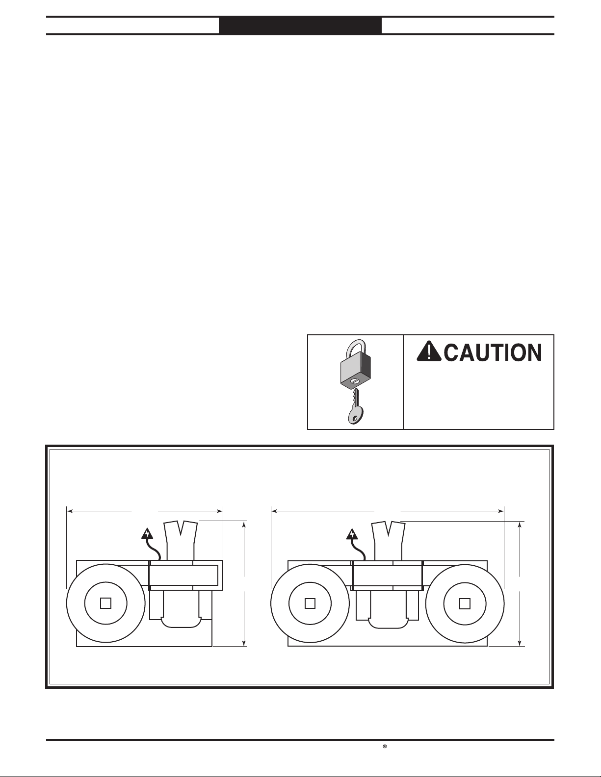
39”
Children or untrained
people may be seriously
SB1101SB1100
58"
311⁄2"
Figure 9. Clearances.Figure 9. Clearances.
injured by this machine.
Only install in an access
restricted location.
311⁄2"
-16 -
Page 20
South Bend Tools
For Machines Mfd. Since 05/21 Model SB1100 & SB1101
PREPARATION
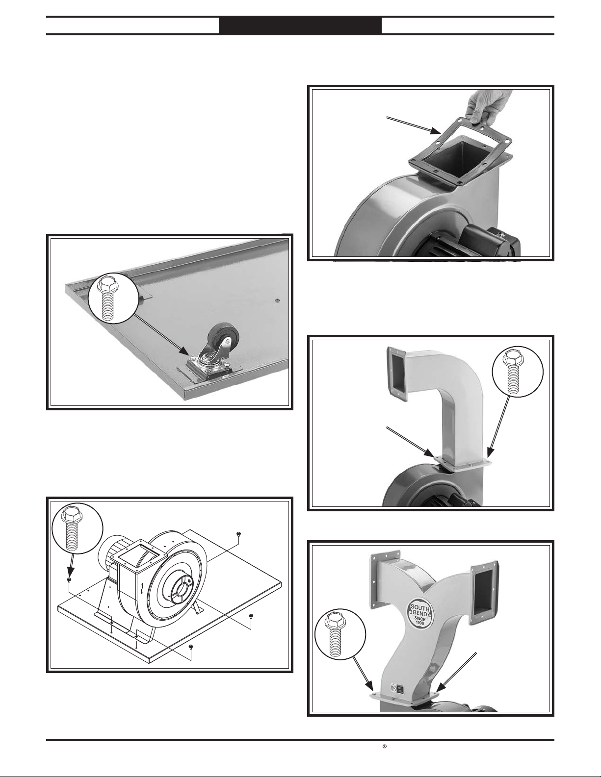
3. Place square gasket on impeller outlet rim
Assembly
(see Figure 12).
The machine must be fully assembled before it
can be operated. Before beginning the assembly
process, refer to Needed for Setup and gather
all listed items. To ensure the assembly process
SquareSquare
GasketGasket
goes smoothly, first clean any parts that are
covered or coated in heavy-duty rust preventative
(if applicable).
To assemble dust collector:
1. Attach (4) swivel casters to base with (16)
5
⁄16"-18 x 1⁄2" flange bolts (see Figure 10).
Figure Figure 12. Square gasket in place on impeller rim. . Square gasket in place on impeller rim.
x16x16
Figure Figure 10. Example of swivel caster attached to base.. Example of swivel caster attached to base.
2. Align motor/impeller assembly with
mounting holes on base. Attach assembly to
5
base with (4)
⁄16"-18 x 1⁄2" flange bolts (see
Figure 11).
x4x4
4. Attach outlet tube to impeller outlet with (5)
5
⁄16"-18 x 1⁄2" flange bolts (see Figures 13 &
14). Do not use three inner mounting holes.
x5x5
Inner Inner
Mounting HoleMounting Hole
Figure Figure 13. SB1100 outlet tube attached. . SB1100 outlet tube attached.
Figure Figure 11. Motor/impeller assembly on base.. Motor/impeller assembly on base.
x5x5
Figure Figure 14. SB1101 outlet tube attached. . SB1101 outlet tube attached.
Inner Inner
Mounting HoleMounting Hole
-17-
Page 21
South Bend Tools
Model SB1100 & SB1101
PREPARATION
For Machines Mfd. Since 05/21
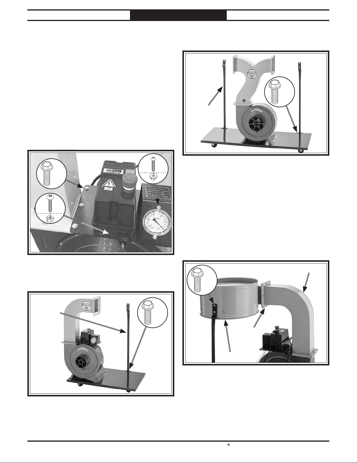
5. Attach pressure gauge to gauge bracket
1
using (2)
and
⁄4"-20 x 1⁄2" button head cap screws
1
⁄4"-20 flange nuts (see Figure 15).
6. Attach gauge bracket to outlet tube with (3)
5
⁄16"-18 x 1⁄2" flange bolts using remaining
mounting holes (see Figure 15).
7. Loosen existing Phillips head screws and
remove switch box cover from switch box (see
Figure 15).
8. Attach switch box to gauge bracket with (2)
3
10-24 x
⁄4" Phillips head screws and 10-24
hex nuts (see Figure 15).
x2x2
x3x3
x2x2
10. SB1101 Only: Repeat Step 9 with second
canister support (see Figure 17).
x4x4
Canister Canister
SupportSupport
(1 of 2)(1 of 2)
Figure Figure 17. SB1101 canister support.. SB1101 canister support.
11. While an assistant holds collector, insert
square gasket between collector and outlet
tube, then secure collector to outlet tube with
5
⁄16"-18 x 1⁄2" flange bolts (see Figure 18).
(8)
IMPORTANT: Collector must be oriented so
canister support aligns with mounting holes
on collector.
Figure Figure 15. Switch box mounted on outlet tube.. Switch box mounted on outlet tube.
9. Attach canister support to base with (2) 5⁄16"-
1
⁄2" flange bolts (see Figure 16).
18 x
Canister Canister
SupportSupport
Figure Figure 16. SB1100 canister support.. SB1100 canister support.
x2x2
12. Attach canister support to collector with (2)
5
⁄16"-18 x 3⁄4" flange bolts (see Figure 18).
Outlet TubeOutlet Tube
x2x2
SquareSquare
GasketGasket
CollectorCollector
Figure Figure 18. Collector attached to outlet tube and . Collector attached to outlet tube and
canister support.canister support.
13. SB1101 Only: Repeat Steps 11–12 with
second collector.
-18 -
Page 22
South Bend Tools
For Machines Mfd. Since 05/21 Model SB1100 & SB1101
PREPARATION
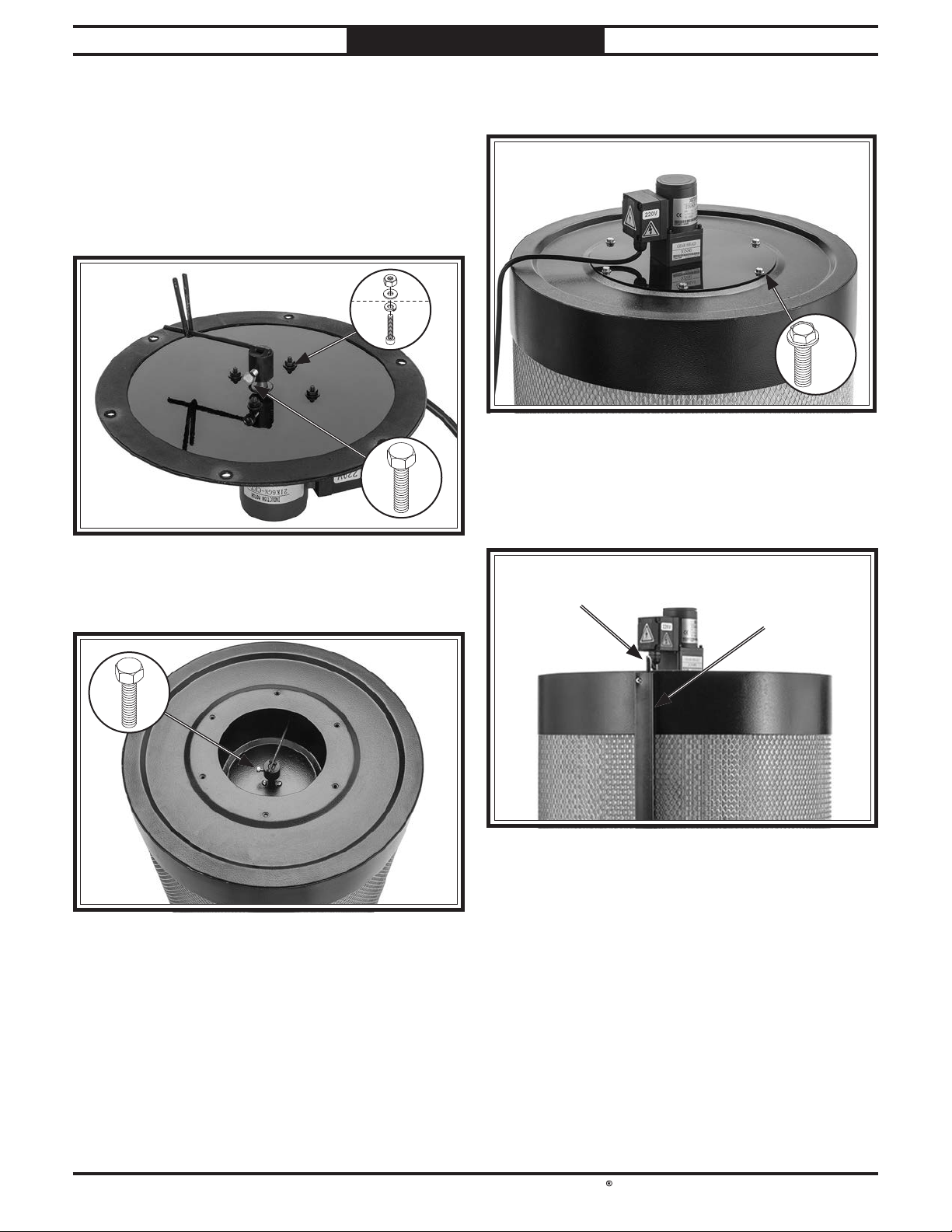
14. Attach filter brush motor and gear reducer
to filter cover with (4) M4-.7 x 60 cap screws,
4mm lock washers, 4mm flat washers, and
M4-.7 hex nuts (see Figure 19).
15. Attach upper alignment arm to gear
reducer spindle with M6-1 x 16 hex bolt
(see Figure 19).
x4x4
Figure Figure 19. Filter cover assembly.. Filter cover assembly.
18. Attach filter cover assembly to canister filter
1
with (6)
Figure Figure 21. Filter cover assembly attached to canister . Filter cover assembly attached to canister
⁄4"-20 x 3⁄4" flange bolts (see Figure 21).
x6x6
filter.filter.
19. Pull motor cord from filter brush motor
through routing cover on canister filter (see
Figure 22).
16. Attach lower alignment arm to filter spindle
with M6-1 x 16 hex bolt (see Figure 20).
Figure Figure 20. Lower alignment arm installed to filter . Lower alignment arm installed to filter
spindle.spindle.
17. Position filter cover assembly over canister
filter. Rotate lower alignment arm so "V" on
upper alignment arm captures lower arm
when mounting holes align.
MotorMotor
CordCord
Figure Figure 22. Filter brush motor cord and routing cover.. Filter brush motor cord and routing cover.
Routing Routing
CoverCover
20. SB1101 Only: Repeat Steps 14–19 with
second canister filter.
-19 -
Page 23
South Bend Tools
Model SB1100 & SB1101
PREPARATION
For Machines Mfd. Since 05/21
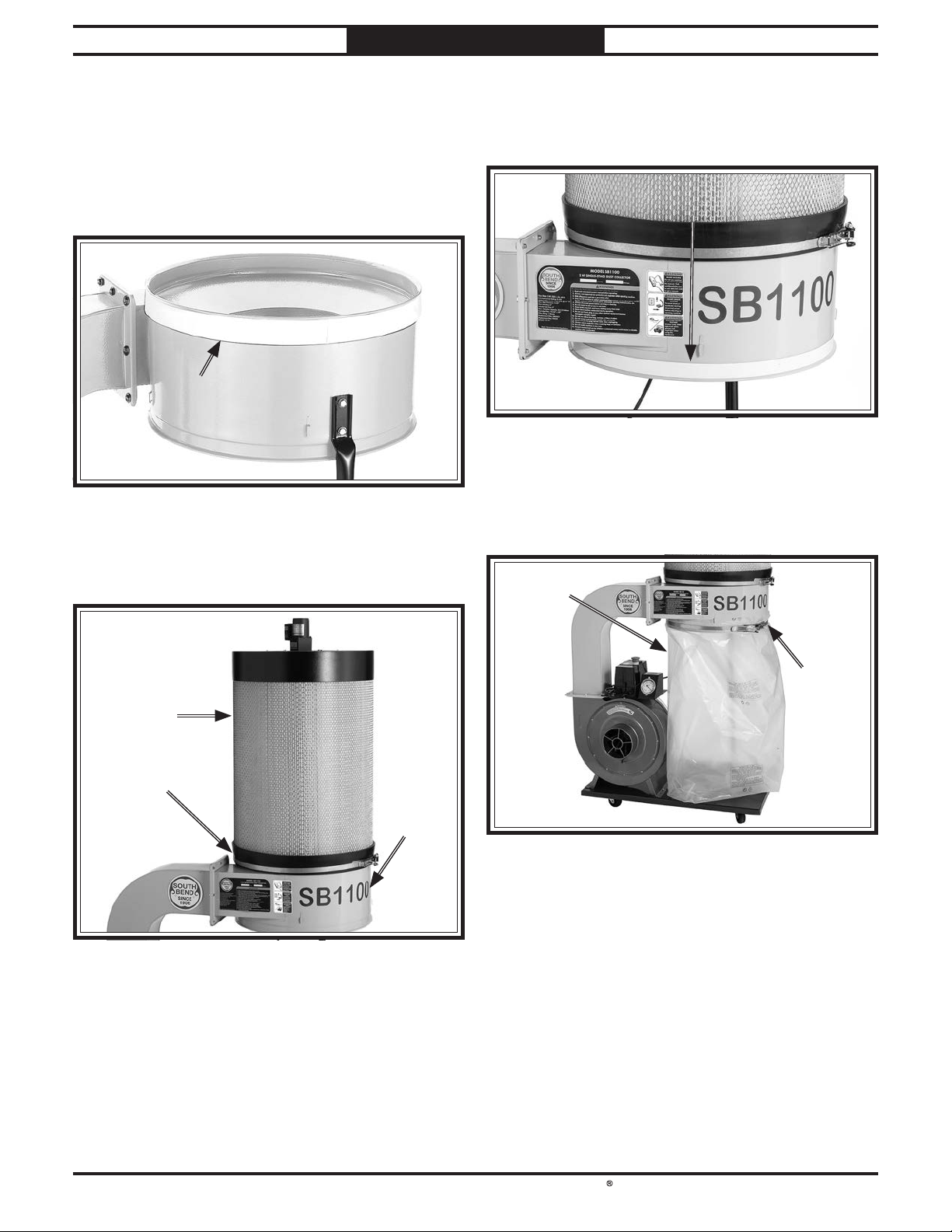
21. Apply 42mm foam tape to outside top rim of
collector (see Figure 23). Trim excess tape
so ends meet evenly without overlap or gap.
Note: DO NOT stretch tape when applying it
to collector. Stretched tape will shrink and
leave a gap, greatly reducing efficiency.
42mm Tape42mm Tape
Figure Figure 23. Tape applied to top rim of collector.. Tape applied to top rim of collector.
22. Position canister clamp around base of
canister filter, then place canister filter over
collector and tighten clamp (see Figure 24).
24. Apply 20mm foam tape to outside bottom rim
of collector (see Figure 25). Trim excess tape
so ends meet evenly without overlap or gap.
20mm 20mm
TapeTape
Figure Figure 25. Tape applied to bottom rim of collector.. Tape applied to bottom rim of collector.
25. Attach collection bag to hooks around bottom
of collector, then position bag clamp around
collector and tighten clamp around bag (see
Figure 26).
Collection Collection
BagBag
Canister Canister
FilterFilter
CanisterCanister
ClampClamp
CollectorCollector
Figure Figure 24. Canister filter secured to collector with bag . Canister filter secured to collector with bag
clamp.clamp.
23. SB1101 Only: Repeat Steps 20–21 with
second canister filter.
Bag Bag
ClampClamp
Figure Figure 26. Collection bag installed to dust collector.. Collection bag installed to dust collector.
26. SB1101 Only: Repeat Steps 23–24 with
second collector.
-20-
Page 24
South Bend Tools
For Machines Mfd. Since 05/21 Model SB1100 & SB1101
PREPARATION
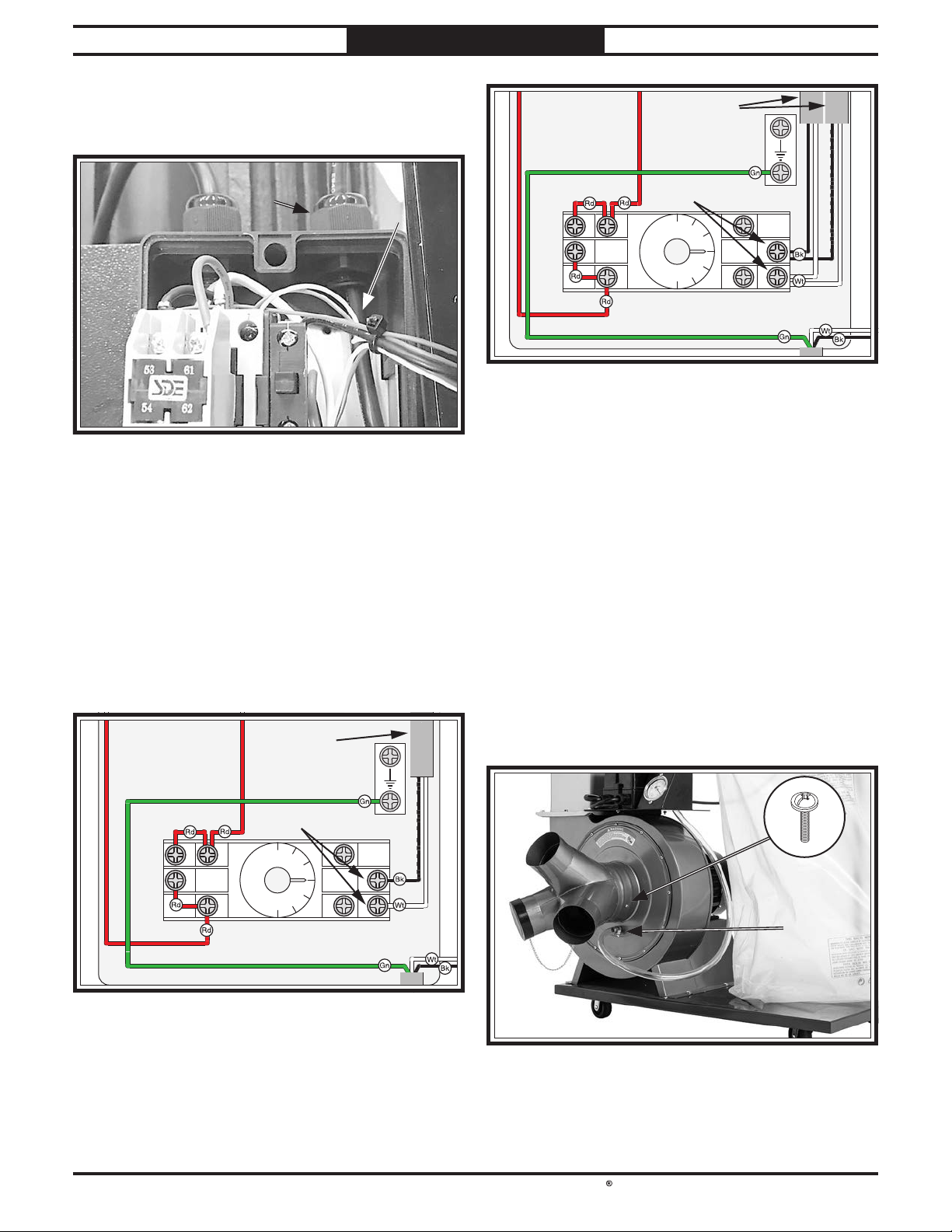
27. Pull motor cord from filter brush motor
through strain relief at top of switch box (see
Figure 27).
StrainStrain
ReliefRelief
Figure Figure 27. Filter brush motor cord routed into switch . Filter brush motor cord routed into switch
box.box.
MotorMotor
CordCord
28. SB1101 Only: Repeat Step 26 with second
filter brush motor cord.
Motor Cords
Ground
Connect
14
12
13
9 5 1
0
3
Timer
8
1
2
H3Y 5A 250VAC
4
Figure Figure 29. SB1101 filter brush motor connection.. SB1101 filter brush motor connection.
Note: For full wiring diagrams, refer to SB1100
Wiring Diagram on Page 45 and SB1101 Wiring
Diagram on Page 48.
30. Tighten strain relief (see Figure 27) to
secure motor cords in position.
29. Connect terminal ends of motor cord(s) to
right terminals of timer inside switch box
(see Figures 28 and 29).
Note: Timer module may be pulled off
terminal block if it is in the way during
connection of motor cords.
Motor Cord
Ground
Connect
14
12
13
9 5 1
0
3
Timer
Figure Figure 28. SB1100 filter brush motor connection.. SB1100 filter brush motor connection.
8
1
2
H3Y 5A 250VAC
4
31. Attach swtich box cover to switch box with
(2) Phillips head screws loosened in Step 7.
32. Attach 1⁄2" hose to pressure gauge and port
3
under impeller intake with and (2)
⁄4" hose
clamps (see Figure 30).
33. Attach inlet adapter to impeller intake, then
3
secure inlet adapter with (1) 10-24 x
⁄8"
flange screw (see Figure 30).
Pressure Pressure
GaugeGauge
Hose Hose
ConnectionConnection
Figure Figure 30. Inlet adapter secured to impeller housing.. Inlet adapter secured to impeller housing.
-21-
Page 25
South Bend Tools
Model SB1100 & SB1101
PREPARATION
Test Run
After all preparation steps have been completed,
the machine and its safety features must be
tested to ensure correct operation. If you discover
a problem with the operation of the machine or
its safety components, do not operate it further
until you have resolved the problem.
Note: Refer to Troubleshooting on Page 42
for solutions to common problems. If you need
additional help, contact our Tech Support at
(360) 734-1540.
The test run consists of verifying the following:
Motor powers up and runs correctly.
•
Emergency Stop button works correctly.
•
Remote control works correctly.
•
Serious injury or death can result from using
this machine BEFORE understanding its
controls and related safety information. DO
NOT operate, or allow others to operate,
machine until the information is understood.
DO NOT start machine until all preceding
setup instructions have been performed.
Operating an improperly set up machine may
result in malfunction or unexpected results
that can lead to serious injury, death, or
machine/property damage.
To test run machine:
1. Clear all setup tools away from machine.
Lock all swivel casters on base stand.
2.
3. Connect machine to dust-collection system or
place covers over inlet adapter ports.
IMPORTANT: DO NOT operate the dust
collector without first connecting it to a dustcollection system or covering an inlet adapter
port. Otherwise, the lack of airflow resistance
will cause the motor to operate at full
amperage load, which could trip your circuit
breaker or blow a fuse.
For Machines Mfd. Since 05/21
4. Press Emergency Stop button in.
5. Connect machine to power.
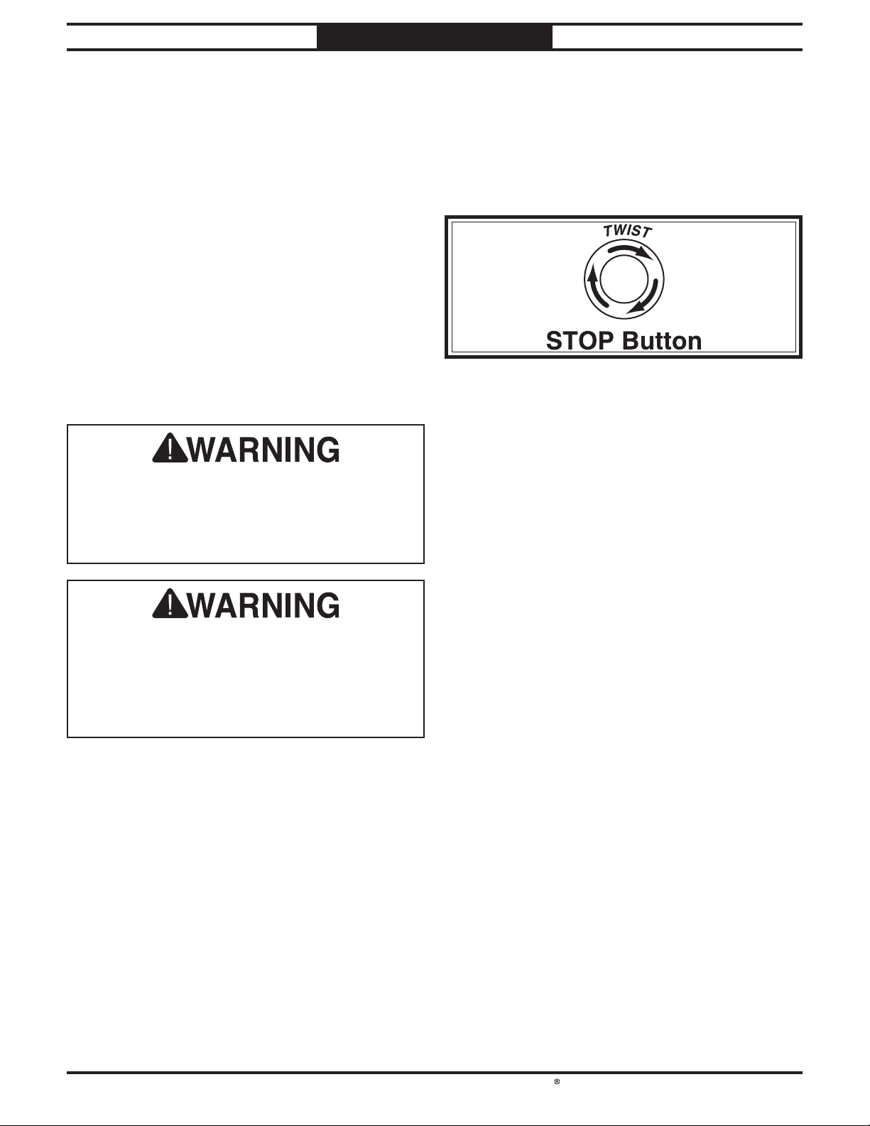
6. Twist Emergency Stop button clockwise until
it springs out (see Figure 31). This resets
the switch so the machine can start.
Figure Figure 31. Resetting the switch.. Resetting the switch.
7. Standing away from intake port, press green
Start button to turn machine ON. Verify
motor starts up and runs smoothly without
any problems or unusual noises.
Press Emergency Stop button to turn
8.
machine OFF.
WITHOUT resetting Emergency Stop
9.
button, try to start machine by pressing the
green Start button. The machine should not
start.
— If the machine does not start, the safety
feature of the Emergency Stop button is
working correctly.
— If the machine does start, immediately
turn it OFF and disconnect power. The
safety feature of the Emergency Stop
button is NOT working properly and
must be replaced before further using the
machine.
To test remote control operation, reset
10.
Emergency Stop button then press remote
ON button to turn motor ON, then press
remote OFF button to turn motor OFF.
— If the machine does NOT start or stop,
press Emergency Stop button to turn
machine OFF. Refer to Pairing Remote
Control & Receiver on Page 41 and
ensure remote control is paired.
Congratulations! The Test Run is complete.
-22-
Page 26
South Bend Tools
For Machines Mfd. Since 05/21 Model SB1100 & SB1101
You have many choices regarding main line and
branch line duct material. For best results, use
smooth
lines, then use short lengths of flexible hose to
connect each machine to the branch lines.
Plastic duct is also a popular material for home
shops. However, be aware that there is a fire or
explosion hazard if plastic duct material is
properly
buildup
end of this section).
plastic
than metal.
The popularity of plastic duct is due to the fact
that it is an economical and readily available
product. It is also simple to assemble and
easily sealed against air loss. The primary
disadvantage of plastic duct for dust collection is
the inherent danger of static electrical buildup.
SYSTEM DESIGN
SYSTEM DESIGN
General Duct Material
metal duct for the main line and branch
Always make sure there are no open flames
or pilot lights in the same room as the dust
collector. There is a risk of explosion if too
much fine dust is dispersed into the air with an
open flame present.
not
grounded to prevent static electrical
(refer to System Grounding at the
Always guard against static
electrical buildup by grounding
all dust collection lines.
duct is that it is less efficient per foot
Another problem with using
The Model SB1100/SB1101 works quite well
as a point-of-use dust collector, or for collecting
dust from up to three machines simultaneously.
The locking swivel casters make it easy to move
around the shop near the machine being used.
Tips for Optimum Performance
• Avoid using more than 10' of flexible hose on
any ducting line. The ridges inside flexible
hose greatly increase static pressure loss,
which reduces suction performance.
• Keep ducts between the dust collector and
machines as short as possible.
Keep ducting directional changes to a
•
minimum. The more curved fittings you use,
the greater the loss of suction at the dustproducing machine.
Gradual directional changes are more
•
efficient than sudden directional changes
(i.e. use 45° elbows in place of 90° elbows
whenever possible).
The simpler the system, the more efficient
•
and less costly it will be.
Plastic duct generates static
electrical buildup that can cause
fire or shock. Properly ground it
to reduce this risk.
Plastic Duct
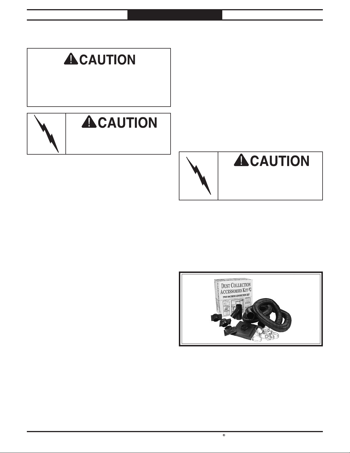
Figure 32. Examples of plastic ducting components. Examples of plastic ducting components.
-23-
Page 27
South Bend Tools
Model SB1100 & SB1101
Advantages of smooth metal duct are its
conductivity
contribute to static electrical charge build-up.
However, static charges are still produced when
dust particles strike other dust particles as they
move through the duct. Since metal duct is a
conductor, it can be grounded quite easily to
dissipate any static electrical charges.
There are a number of options when it comes
to metal duct, but metal duct that is specially
manufactured for dust collection is the best
choice. When selecting your metal duct, choose
high quality metal duct with smooth welded
internal seams that will minimize airflow
resistance. This type of duct usually connects to
other ducts or elbows with a simple, self-sealing
clamp, is very quick and easy to assemble, and
can be readily dismantled and re-installed
a different configuration
important if you ever need to change things
around in your shop or add more tools.
Avoid inferior metal duct that requires you to
cut it to length and snap it together. This type
of duct is time consuming to install because it
requires you to seal all the seams with silicone
and screw the components on the ends with
sheet metal screws. Another disadvantage is
the rough internal seams and crimped ends that
unavoidably increase static pressure loss.
Flexible hose is generally used for short runs,
small shops and at rigid duct-to-tool connections.
There are many different types of flex hose on
the market today. These are manufactured from
materials such as polyethylene, PVC, cloth hose
dipped in rubber and even metal, including steel
and aluminum.
The superior choice here is metal flex hose that
is designed to be flexible, yet be as smooth as
possible inside to reduce static pressure loss.
There are also many kinds of pure plastic flexible
hose, such as non-perforated drainage type
hose and dryer vent hose. Drainage type hose,
while being economical, does not quite have
the flexibility required for dust collection. The
inside of the duct is also deeply corrugated and
can increase the static pressure loss by as much
as 50% over smooth wall duct. Dryer vent hose,
while being completely flexible, is non-resistant
to abrasion and has a tendency to collapse
in a negative pressure system. We DO NOT
recommend using dryer vent hose in your dust
collection system.
If using flex-hose, you should choose one of the
many types that are designed specifically for the
movement of solid particles, i.e. dust, grains
and plastics. However, the cost of specifically
designed flexible duct can vary greatly.
Grizzly
is well suited for the removal of particulate
matter, especially sawdust, since it is durable
and completely flexible. Polyethylene is also very
economical and available in a wide variety of
diameters and lengths for most applications.
SYSTEM DESIGN
Metal Duct Flexible Duct
, efficiency, and that it does not
For Machines Mfd. Since 05/21
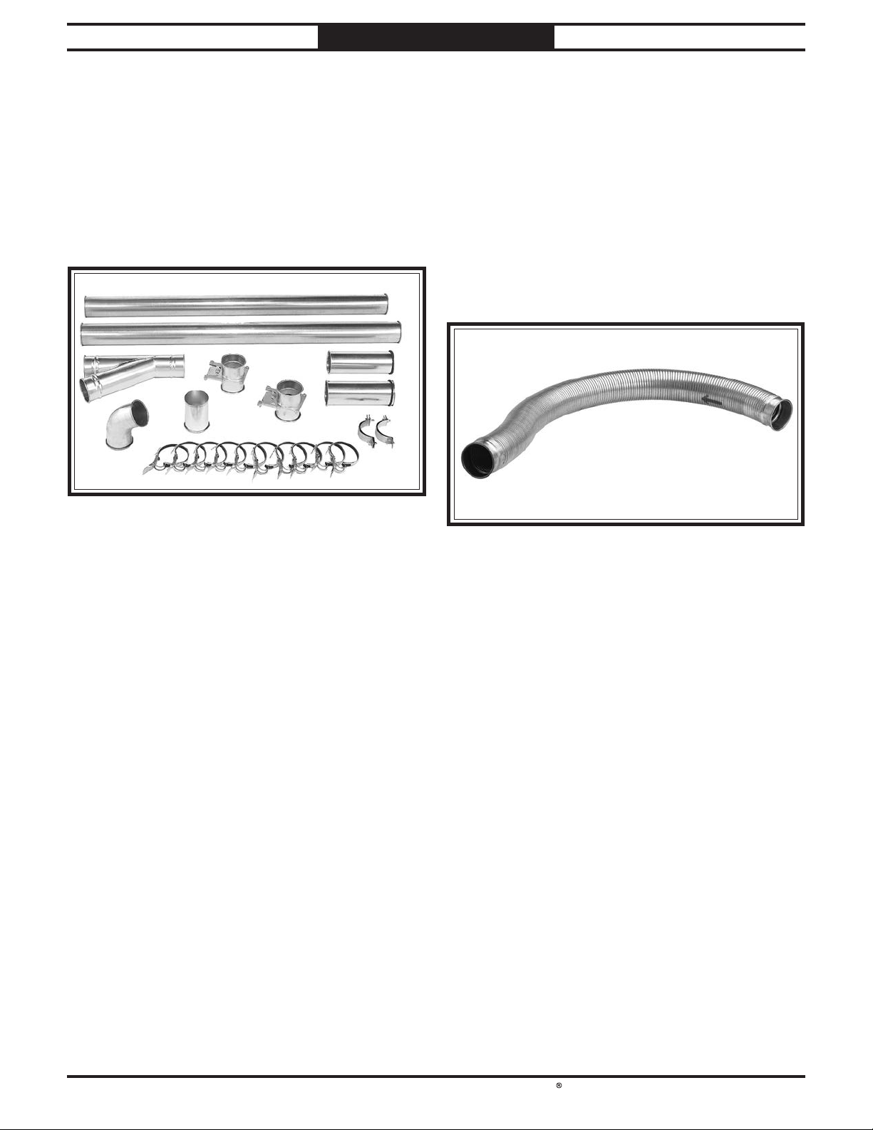
Figure Figure 33. Examples of smooth metal duct and . Examples of smooth metal duct and
components.components.
-24-
. This is especially
Figure Figure 34. Example of flexible metal duct.. Example of flexible metal duct.
in
,
.com offers polyethylene hose, which
Page 28
South Bend Tools
For Machines Mfd. Since 05/21 Model SB1100 & SB1101
For most small-to-medium sized shops, you
can
yourself without hiring engineers or consultants.
We have included some basic information here to
get you started on a basic design.
If you have a large shop or
complicated system, we recommend
additional research beyond this manual or
seeking the help of an expert.
When designing a successful dust collection
system, planning is the most important step.
In this step, sketch a basic layout of your shop
including space requirements of different
machines
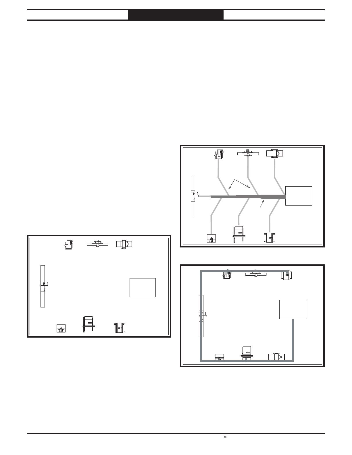
Your sketch only needs the basic details of
the shop layout, similar to
including all your current/planned machines and
your planned placement of the dust collector.
For the next step, sketch how you will connect
your machines to the dust collector. Consider
these general guidelines for an efficient system:
1.
should be placed nearest to the dust collector
2.
duct layouts.
3. Directional changes should be kept to a
fittings you use directly increases the overall
SYSTEM DESIGN
System Design
Decide Who Will Design
design and build the dust collection system
plan to design a
doing
Sketch Your Shop Layout
.
Sketch a Basic Duct Layout
Machines that produce the most saw dust
(i.e. planers and sanders).
Ideally, you should design the duct system
to have the shortest possible main line and
secondary branch ducts. See the figures
below for ideas of efficient versus inefficient
Branch
,
Line
Ducts
GOOD
Dust
Collector
the figure below,
Dust
Collector
Figure Figure 35. Basic sketch of shop layout.. Basic sketch of shop layout.
Main
Line Duct
Figure 36. Efficient duct layout.
Dust
BAD
Figure 37. Inefficient duct layout.
minimum. The more directional change
Collector
-25-
Page 29
South Bend Tools
Model SB1100 & SB1101
Since each machine produces a different amount
of sawdust, the requirements for the minimum
amount of CFM to move that sawdust is unique
to the machine (for example, a planer produces
more sawdust than a table saw). Knowing this
required CFM is important to gauging which size
of duct to use.
Refer to the figure below for a close estimation of
the airflow
that machines that generate the most sawdust
should be placed closest to the dust collector. If
the machine has multiple dust ports, the total
CFM required is the sum of all ports.
If the machine does not have a built-in dust port,
use
to determine which size of
dust port to install.
Write the required CFM for each machine on
your sketch, as shown in the figure below.
4. Gradual directional changes are more
5.
6.
and less costly it will be.
SYSTEM DESIGN
For Machines Mfd. Since 05/21
efficient than sudden directional changes
(i.e. use the largest corner radius possible
when changing hose or pipe direction).
Each individual branch line should have a
blast gate immediately after the branch to
control suction from one machine to another.
The simpler the system, the more efficient
Determine Required CFMs
each machine requires. Keep in mind
the following table
Machine Average Dust Port Size
Table Saw ......................................................... 4"
Miter/Radial-Arm Saw .....................................2"
Jointer (6" and smaller) ................................... 4"
Jointer (8"-12") .................................................5"
Thickness Planer (13" and smaller) ................ 4"
Thickness Planer (14"-20") ..............................6"
Shaper ...............................................................4"
Router (mounted to table) ................................2"
Bandsaw ...........................................................4"
Lathe ................................................................. 4"
Disc Sander (12" and smaller) ......................... 2"
Disc Sander (13-18") ........................................4"
Belt Sander (6" and smaller) ........................... 2"
Belt Sander (7"-9") ...........................................3"
Edge Sander (6" x 80" and smaller) ................4"
Edge Sander (6" x 80" and larger) ................... 5"
Drum Sander (24" and smaller) ................ 2 x 4"
Drum Sander (24" and larger) ................... 4 x 4"
Widebelt Sander (18" and smaller) .................5"
Widebelt Sander (24"-37" single head) ..... 2 x 6"
Widebelt Sander (24"-51" double head) .... 5 x 4"
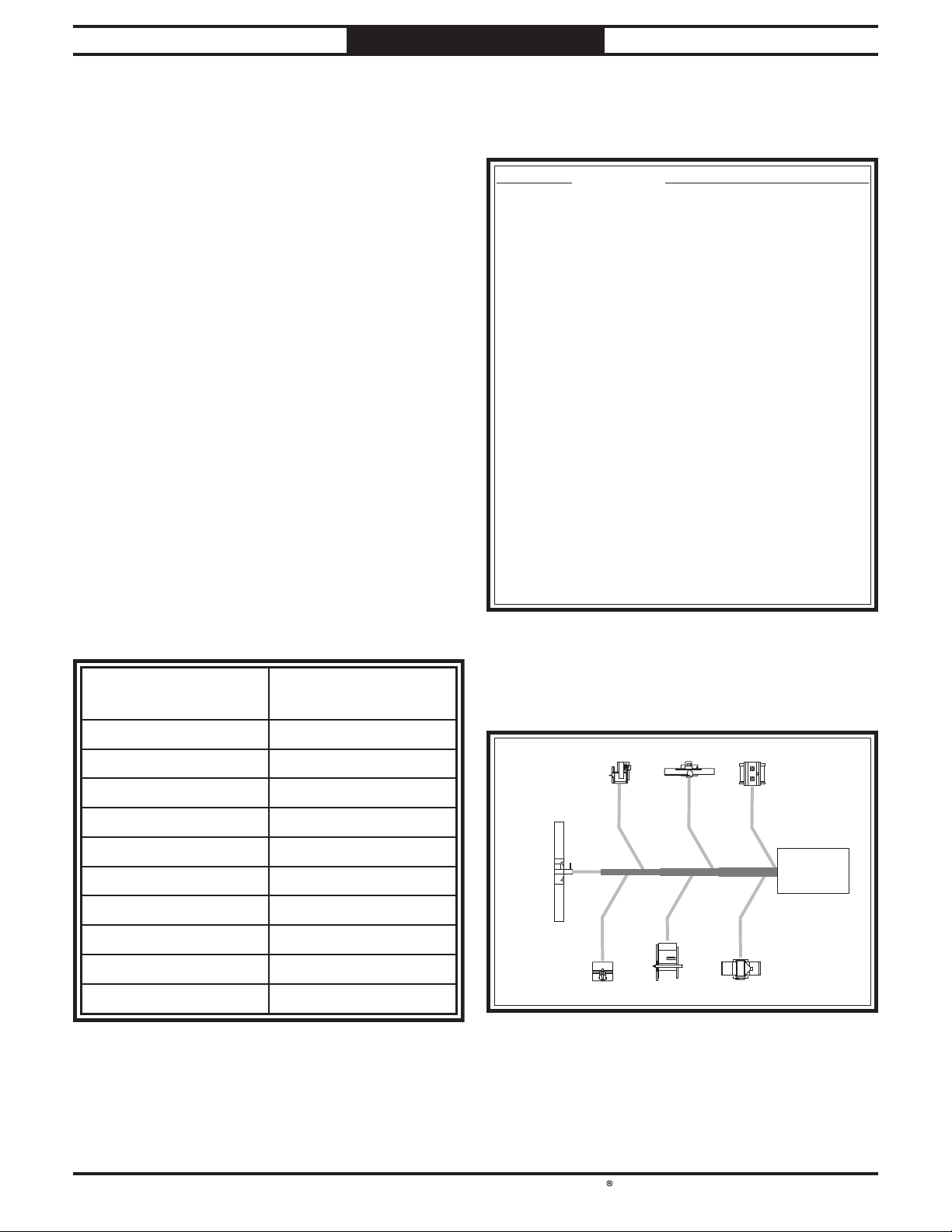
Machine
Dust Port Size
Approximate
Required CFM
2" 100
2.5" 150
3" 250
4" 400
5" 600
6" 850
7" 1200
8" 1600
Figure 38. Approximate required air flow for machine,
9" 2000
10" 2500
based on dust port size.
Figure 39. Dust port size and quantity per average
machine.
Planer/
Moulder
Miter
Saw
100
250
Figure 40. CFM requirements labeled for each
Jointer Sander
400
400
Table Saw
machine.
850400
Dust
Collector
600
PlanerShaper
-26-
Page 30
South Bend Tools
For Machines Mfd. Since 05/21 Model SB1100 & SB1101
The general rule of thumb for a main line duct
is that the velocity of the airflow must not fall
below 3500 FPM.
For small/medium sized shops, using the inlet
size of the dust collector as the main line duct
size will usually keep the air velocity above 3500
FPM and, depending on your system, will allow
you to keep multiple branches open at one time.
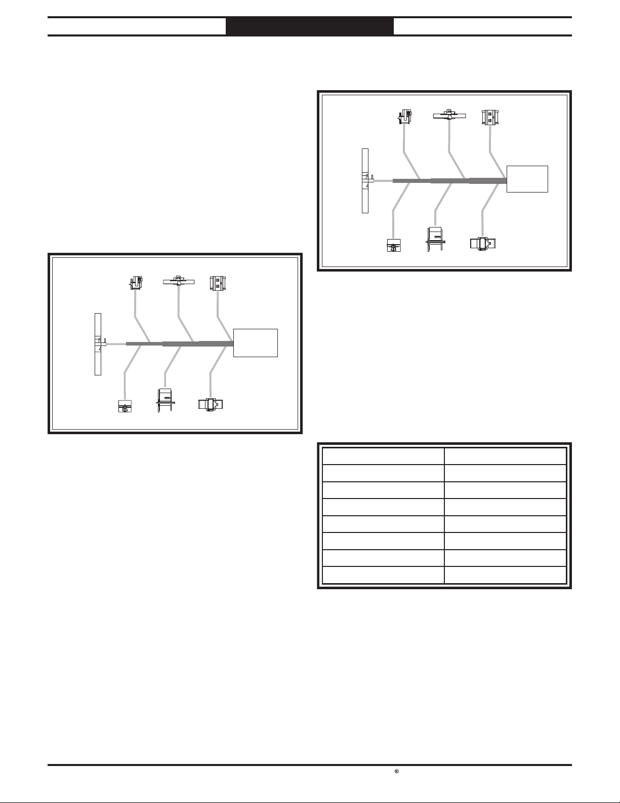
Mark your drawing
below
collector as the main line.
The general rule of thumb for a branch line duct
is that the velocity of the airflow must not fall
below 4000 FPM.
For small/medium sized shops, using the dust
port size from the machine as the branch line
duct size will achieve the correct velocity in most
applications. However, if the dust port on the
machine is smaller than 4", make the branch line
4" and neck the line down right before the dust
port.
Note:
better if multiple blast gates are left open. This
also allows you to run two machines at once.
Experiment with different combinations of blast
gates open/closed to find the best results for your
system.
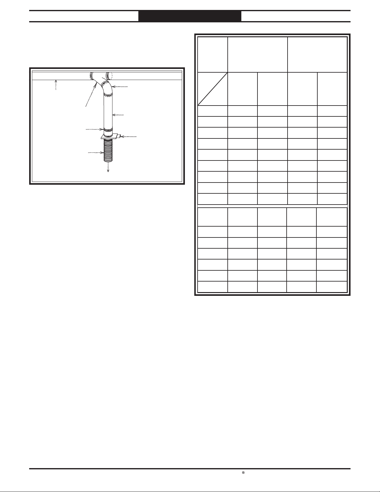
Write your determined branch line sizes on your
drawing, as shown in the following figure.
If two machines will connect to the same branch
line and
add the required CFM for each machine together
and find the closest total CFM in the table below
to determine the correct branch size
If both machines will never run at the same time,
reference the machine with
in the table below
Y-branch to open/close the line to each machine.
SYSTEM DESIGN
Determine Main Line Duct Size
, as shown in the figure
, but using the inlet size for your dust
Jointer Sander
250
Table Saw
400
400
850400
Dust
Collector
600
PlanerShaper
Miter
Saw
100
Planer/
Moulder
5" 6" 7"
Planer/
Moulder
Miter
Saw
100
Figure 42. Branch line duct sizes labeled.
both will operate at the same time, then
5" 6" 7"
4"
4" 4" 5"
250
Jointer Sander
400
4"
Table Saw
and add blast gates after the
400
4" 6"
400
the biggest dust port
850
Collector
600
PlanerShaper
.
Dust
Figure 41. Main line size labeled on sketch.
Determine Branch Line Duct Size
Systems with powerful dust collectors work
Total CFM Branch Line Size
400 4"
500 4"
600 5"
700 5"
800 6"
900 6"
1000 6"
Figure 43. Sizing chart for multiple machines on the
same branch line.
-27-
Page 31
South Bend Tools
Model SB1100 & SB1101
Plan the drop downs for each machine, using
blast gates wherever possible to control airflow.
Adding duct work, elbows, branches and any
other components to a duct line increases airflow
resistance (static pressure loss). This resistance
can be minimized by using rigid (smooth)
and gradual curves, as opposed to flexible
and 90˚ elbows.
To help you think about this resistance, imagine
riding a bicycle in a tunnel that is an exact
replica of your duct work. If the inside of the
tunnel is very bumpy (flexible
) and has a lot
of sharp turns (90˚ elbows), it will take a lot more
effort to travel from one end to the other.
The purpose of calculating the resistance is to
determine if it is low enough from the machine
to the dust collector to meet the given CFM
requirement for the machine. Use the
tables to calculate the resistance of duct work.
In most small/medium shops it is only necessary
to calculate the line with the longest duct
length or the most fittings (operating under the
assumption that if the line with the highest
resistance works, the others will be fine).
To calculate the static pressure of any given
line in the system, follow these steps:
1.
2.
SYSTEM DESIGN
For Machines Mfd. Since 05/21
Planning Drop Downs
Elbow
Rigid Duct
(Main Line)
Y Branch
Clamp
Flexible Duct
To Planer
Figure 44. Drop-down setup.
Rigid Duct
Blast Gate
Calculating Duct Resistance
Duct
Dia.
Approximate
Static Pressure
Loss Per Foot of
Rigid Duct
Main
Lines
at 3500
FPM
Branch
Lines
at 4000
FPM
Approximate
Static Pressure
Loss Per Foot of
Flexible Duct
Main
Lines
at 3500
FPM
Branch
Lines
at 4000
FPM
2" 0.091 0.122 0.35 0.453
2.5" 0.08 0.107 0.306 0.397
3" 0.071 0.094 0.271 0.352
4" 0.057 0.075 0.215 0.28
5" 0.046 0.059 0.172 0.225
6" 0.037 0.047 0.136 0.18
7" 0.029 0.036 0.106 0.141
8" 0.023 0.027 0.08 0.108
9" 0.017 0.019 0.057 0.079
Fitting
Dia.
90˚
Elbow
45˚
Elbow
45˚
Wye(Y)
90˚
Wye(Y)
duct
following
duct
duct
3" 0.47 0.235 0.282 0.188
4" 0.45 0.225 0.375 0.225
5" 0.531 0.266 0.354 0.236
6" 0.564 0.282 0.329 0.235
7" 0.468 0.234 0.324 0.216
8" 0.405 0.203 0.297 0.189
Figure 45. Static pressure loss charts.
Make a list of each size duct in the line,
including the length, and multiply those
numbers by the static pressure value given
in the previous table.
List each type of elbow or branch and
multiply the quantity (if more than one) by
the static pressure loss given in the previous
-28-
Page 32
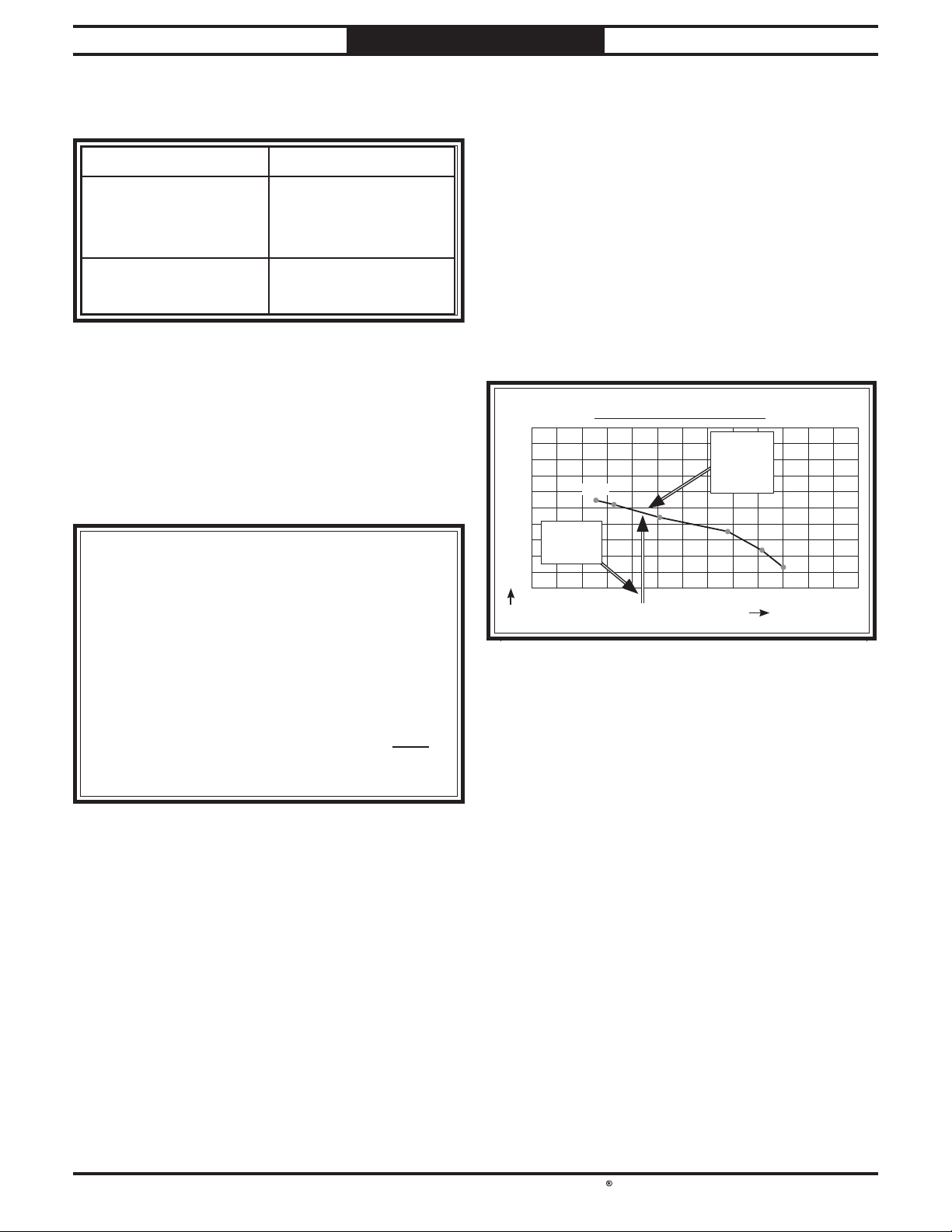
South Bend Tools
For Machines Mfd. Since 05/21 Model SB1100 & SB1101
3. Add the additional factors from the following
table to your list.
4. Total your list as shown in the example
works right when the fi lter is clean.
Note: When calculating static pressure loss
numbers once.
5. Compare the total static pressure loss for
closest CFM given on the per-
A typical Data Sheet Performance
Curve is illustrated in the figure below. Find
the total static pressure loss on the Static
Pressure axis (4.4 in the current example),
then refer to the closest value on the CFM
The 1120 CFM for the static pressure loss of
the line connected to the router is well above
the 220 CFM requirement of that machine.
— If the CFM for your static pressure loss
to
make your system a reality.
— If the CFM for your static pressure loss is
below the requirement of the machine, then
with 45˚ elbows.
G0440 MACHINE
DATA SHEET
SYSTEM DESIGN
that line to the
formance curve for your dust collector.
Additional Factors Static Pressure
Seasoned (well
used) Dust
1"
Collection Filter
Entry Loss at Large
2"
Machine Hood
Figure 46. Additional factors affecting static pressure.
below to come up with your overall static
pressure loss number for that line.
Note: Always account for a seasoned fi lter,
so you don't end up with a system that only
Main Line
6" Rigid Duct (0.037) at 20' ................ 0.740
Branch Line
4" Rigid Duct (0.075) at 10' ................ 0.750
4" Flexible Duct (0.28) at 5' ................ 1.400
Example:
axis—approximately 1120 CFM.
Performance Curve
2500
2250
2000
1750
1500
1250
1000
750
500
250
0
0.0 1.0 2.0 3.0 4.0 5.0 6.0 7.0 8.0 9.0 10.0 11.0 12.0 13.0
CFM
1354
4.4 SP 4.4 SP
Loss Loss
STATIC PRESSURE (Inch/H2O)
Closest Closest
CFMCFM
(1120)(1120)
Elbows/Branches
6" 45˚ Y-Branch ................................ 0.329
4" 45˚ Elbow ........................................ 0.225
Additional Factors
Seasoned Filter ................................ 1.000
Total Static Pressure Loss ........................ 4.444
Figure 47. Totaling static pressure numbers.
to determine if multiple lines can be left open
at the same time, only include the main line
Figure 48. CFM for static pressure loss of line
connected to a dust collector and router.
is above the requirement of the machine
connected to the end of that branch line,
then dust collection will most likely be
successful. Congratulations! You've just
designed your own dust system. Refer to
the Accessories section of this manual
start buying the components necessary to
that line will not effectively collect the dust.
You must then modify some of the factors
in that line to reduce the static pressure
loss. Some of the ways to do this include 1)
installing larger duct, 2) reducing amount
of flexible duct used, 3) increasing machine
dust port size, 4) moving machine closer to
dust collector to eliminate duct length, and
5) reducing 90˚ elbows or replacing them
-29-
Page 33
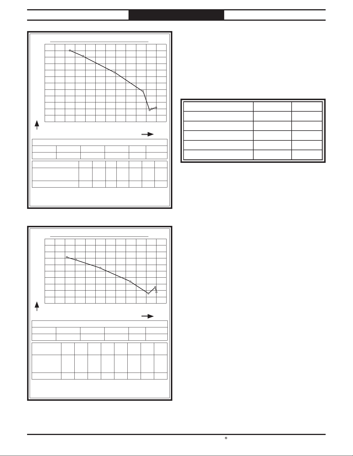
South Bend Tools
Model SB1100 & SB1101
After the system is designed, create a materials
list of all the items you will need to build your
dust collection system. This will make it easy
when it comes time to purchase the materials.
Below is an example of some items that might be
SYSTEM DESIGN
For Machines Mfd. Since 05/21
SB1100 Performance Curve
1200
1100
1000
900
800
700
600
500
400
300
200
100
0
CFM
2 HP DUST COLLECTOR PERFORMANCE RESULTS
Max CFM Max SP HP Volts Inlet Impeller
1132 11.95 2 HP 220V 6" 12"
Restrictor Plate Dia. 6"
Static Pressure
(Inch/H2O)
CFM 1103 1013 759 475 187 200 212
The air flow test probe is located 1.5x duct diameter upstream
from the air inlet. Test pipe length is a minimum of 10x duct
diameter.
11031103
2.0 3.0 4.0 5.0 6.0 7. 0 8.0 9.0 10.0 11.0 12.0
STATIC PRESSURE (Inch/H2O)
5" 4" 3" 2" 1" 0"
3.5 4.8 7.9 10.7 11.4 11.5 12.0
Example Materials List
Description Model Quantity
6" Rigid Duct at 20' G7364 4
4" Rigid Duct at 10' G6162 2
4" Flex Hose at 5' H7215 6
6" 45° Y-Branch G7353 6
4" 45° Elbow G6167 6
Figure 51. Example materials list.
Figure 49. SB1100 performance data.
SB1101 Performance Curve
2000
1800
1600
1400
1200
1000
800
600
400
200
0
CFM
3 HP DUST COLLECTOR PERFORMANCE RESULTS
Max CFM Max SP HP Volts Inlet Impeller
1429 12.03 3 HP 240V 7" 12
Restrictor
Plate Dia.
Static
Pressure
(Inch/H2O)
CFM 1429 1328 1115 667 319 305 491 360
The air flow test probe is located 1.5x duct diameter upstream
from the air inlet. Test pipe length is a minimum of 10x duct
diameter.
14291429
2.0 3.0 4.0 5.0 6.0 7. 0 8.0 9.0 10.0 11.0 12.0
STATIC PRESSURE (Inch/H2O)
3
⁄4"
7" 6"
3.2 4.1 6.5 9.4 11.3 11.7 11.9 12.0
5" 4" 3" 2" 1" 0"
Figure 50. SB1101 performance data.
-30-
Page 34
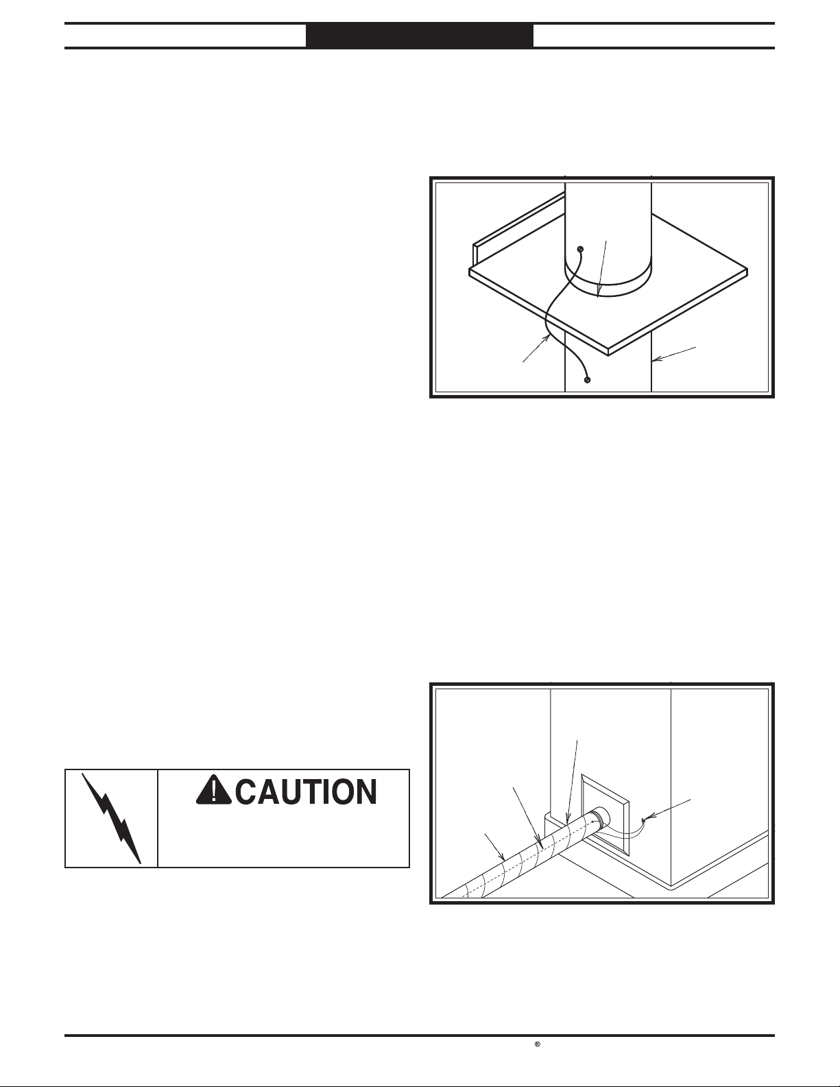
South Bend Tools
For Machines Mfd. Since 05/21 Model SB1100 & SB1101
Since plastic hose is abundant, relatively
inexpensive, easily assembled and air tight, it is
a very popular material for conveying dust from
woodworking machines to the dust collector.
We recommend
of
woodworking machine to the dust collector.
However, plastic flex-hose and plastic duct are
an insulator, and dust particles moving against
the walls of the plastic duct create a static
electrical buildup. This charge will build until it
discharges to a ground.
If a grounding medium is not available to
prevent static electrical buildup, the electrical
charge will arc to the nearest grounded source.
This electrical discharge may cause an explosion
and subsequent fire inside the system.
To protect against static electrical buildup inside
a non-conducting duct, a bare copper wire should
be placed inside the duct along its length and
grounded to the dust collector. You must also
confirm that the dust collector is continuously
grounded through the electrical circuit to the
electric service panel.
If you connect the dust collector to more than
one machine by way of a non-conducting
branching duct system and blast gates, the
system must still be grounded as mentioned
above. We recommend inserting a continuous
bare copper ground wire inside the entire duct
system and attaching the wire to each grounded
woodworking machine and dust collector.
We also recommend wrapping the outside of all
plastic ducts with bare copper wire to ground
the outside of the system against static electrical
buildup. Wire connections at Y’s and T’s should
be made with wire nuts.
Attach the bare ground wire to each stationary
woodworking machine and attach to the dust
collector frame with a ground screw as shown in
the f
continuously grounded to the grounding terminal
in your electric service panel.
Be sure that you extend the bare copper wire
down all branches of the system. Do not forget
to connect the wires to each other with wire
nuts when two branches meet at a “Y” or “T”
Ensure that the entire system is grounded.
If using plastic blast gates to direct air flow,
the grounding wire must be jumped (
f
interruption to the grounding system.
SYSTEM DESIGN
System Grounding
see the
igure below) around the blast gate without
only using short lengths
flexible hose (flex-hose) to connect the
Plastic Blast
Gate
Metal Duct
Copper
Ground Wire
Figure 52. Ground jumper wire when using plastic
blast gates and metal duct.
igure below. Ensure that each machine is
Always guard against static
electrical buildup by grounding
all dust collection lines.
External
Ground Wire
Internal
Ground Wire
Flex-Hose
Figure 53. Flex-hose grounded to machine.
Ground
Screw
-31-
Page 35
South Bend Tools
Model SB1100 & SB1101
The purpose of this overview is to provide
the novice machine operator with a basic
understanding of how the machine is used during
operation, so they can more easily understand
the controls discussed later in this manual.
Note:
it is not intended to be an instructional guide
for performing actual machine operations.
To learn more about specific operations and
machining techniques, seek training from people
experienced with this type of machine, and do
additional research outside of this manual by
reading "how-to" books, trade magazines, or
websites.
OPERATION
For Machines Mfd. Since 05/21
OPERATION
Operation Overview
Due to the generic nature of this overview,
To reduce the risk of
serious injury when using
this machine, read and
understand this entire
manual before beginning
any operations.
This single-stage dust collector pulls wood
dust past the impeller, which is then caught
by a canister filter and deposited in the
plastic collection bag below. The spunbond
polyester filter catches 99.9 percent of particles
2 - 5 micron in size, and is pleated to provide
maximum surface area for efficient air flow.
To maintain CFM after heavy use, the automatic
filter brush knocks caked-on dust into the
collection bag when the machine is turned OFF.
To complete a typical operation, the operator
does the following:
1. Locks dust collector swivel casters.
2. Closes blast gates to direct vacuum pressure
to desired machine.
3. Turns woodworking machine ON.
4. Turns dust collector ON.
5. Performs woodworking operation.
6. Turns woodworking machine OFF.
During operation, small
wood chips and dust may
become airborne, leading
to serious eye injury or
lung damage. Wear safety
glasses and a respirator to
reduce this risk.
7. Turns dust collector OFF.
-32-
Page 36
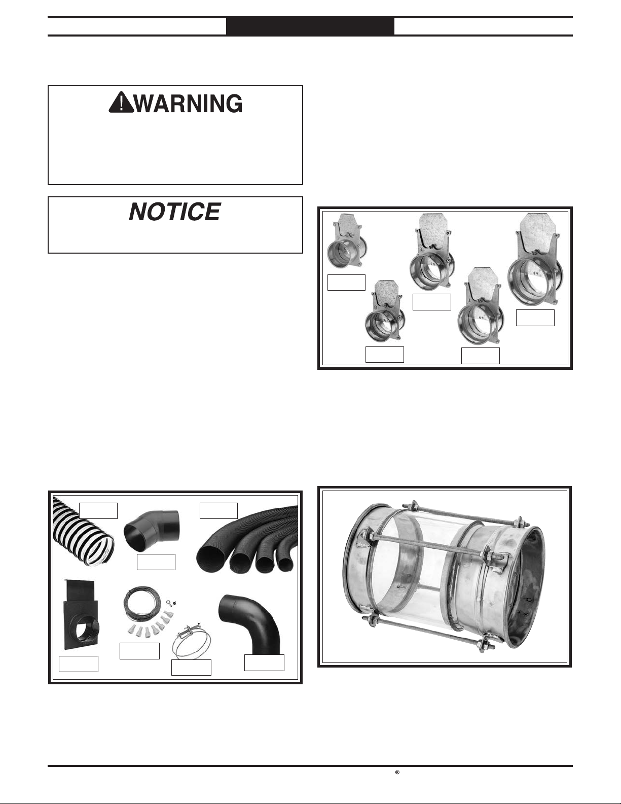
South Bend Tools
For Machines Mfd. Since 05/21 Model SB1100 & SB1101
order online at www.grizzly.com or call 1-800-523-4777
ACCESSORIES
ACCESSORIES
Accessories
Installing unapproved accessories may
cause machine to malfunction, resulting in
serious personal injury or machine damage.
To reduce this risk, only install accessories
recommended by South Bend or Grizzly.
Refer to Grizzly's website or latest catalog for
additional recommended accessories.
This section includes the most common
accessories available for your machine, which
are available through our exclusive dealer,
Grizzly Industrial, Inc., at grizzly.com.
D4206—Clear Flexible Hose 4" x 10'
D4256—45° Elbow 4"
D4216—Black Flexible Hose 4" x 10'
W1034—Heavy-Duty Clear Flex Hose 4" x 10'
D2107—Hose Hanger 4 1⁄4"
W1015—Y-Fitting 4" x 4" x 4"
W1017—90° Elbow 4"
W1019—Hose Coupler (Splice) 4"
W1317—Wire Hose Clamp 4"
W1007—Plastic Blast Gate 4"
W1053—Anti-Static Grounding Kit
G6177—4" Metal Blast Gate
G7340—5" Metal Blast Gate
G7358—6" Metal Blast Gate
H5234—7" Metal Blast Gate
H5249—8" Metal Blast Gate
Control air flow and resistance between
machines. These industrial blast gates can take
the abuse of thousands of open and close cycles.
Made specifically for production shops. These
metal industrial dust collection fittings are
simply the best you can find.
G6177G6177
G7358G7358
H5249H5249
G7340G7340
Figure 55. Metal blast gate assortment. Metal blast gate assortment.
T27422—Viewing Spool 8"
This viewing spool is a section of acrylic glass
with QF ends so you can keep an eye on your
material flow. Makes it a cinch to check for slowdowns or debris! Ends are 22 gauge, 8" opening.
Total length 12.5".
H5234H5234
D4206D4206
D4256D4256
W1053W1053
W1007W1007
Figure 54. 4" dust-collection accessories.
W1317W1317
D4216D4216
W1017W1017
Figure 56. T27422 Viewing Spool. T27422 Viewing Spool.
-33-
Page 37
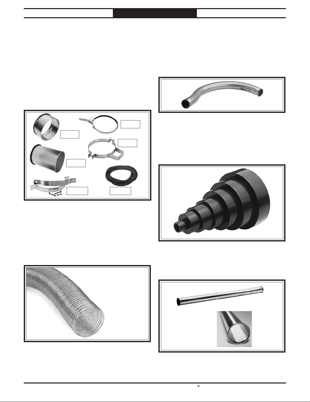
South Bend Tools
Model SB1100 & SB1101
order online at www.grizzly.com or call 1-800-523-4777
ACCESSORIES
For Machines Mfd. Since 05/21
H7428—8" Industrial Dust Collection Machine
Adapter
H5228—8" Industrial Dust Collection Pipe Clamp
H5229—8" Industrial Dust Collection Adjustable
Nipple
H5250—8" Industrial Dust Collection Pipe
Hanger
T26510—8" Industrial Dust Collection Clamp
Hanger
T27054—8" Quick-Fit O-Ring, 12-Pk.
T28548—8" x 6" x 6" Industrial Dust Collection
Standard Branch
H5228H5228
H7428H7428
H5250H5250
H5229H5229
H7217—6" x 5' Rigid Flex Hose
H7218—7" x 5' Rigid Flex Hose
H7219—8" x 5' Rigid Flex Hose
These Rigid Flex Hoses with rolled collars
provide just enough flexibility to make difficult
connections while still keeping the inside wall
smooth.
Figure 59. Rigid flex hose. Rigid flex hose.
W1039—Universal Adapter
This adapter provides a multitude of reducing
options. Simply cut off unneeded steps. Outside
1
diameter sizes include 1", 2", 2
1
6". Wall thickness is
⁄8".
⁄2", 3", 4", 5", and
T26510T26510 T27054T27054
Figure 57. 8" dust-collection accessories.
H7465—8" x 10' Dust Hose
H7463—7" x 10' Dust Hose
W1036—6" x 10' Dust Hose
Spiral-wire-reinforced clear hose allows easy
inspection for locating potential clogs in your
duct system. Uses RH fittings. Available in
additional diameters and lengths.
Figure 60. W1039 Universal Adapter.
G6162—4" x 5' Straight Metal Pipe
G7346—5" x 5' Straight Metal Pipe
G7364—6" x 5' Straight Metal Pipe
Figure 58. Flexible clear dust hose. Flexible clear dust hose.
Figure 61. Straight metal pipe.
-34-
Page 38
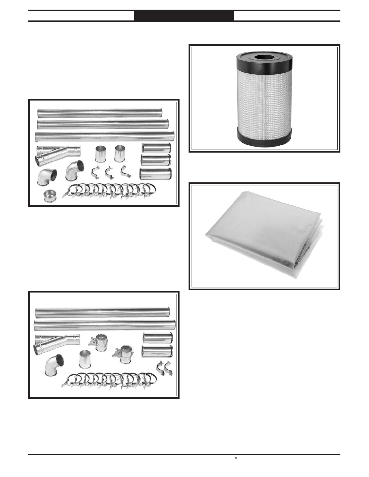
South Bend Tools
For Machines Mfd. Since 05/21 Model SB1100 & SB1101
order online at www.grizzly.com or call 1-800-523-4777
ACCESSORIES
H5293—4" Metal Duct Starter Kit
H5295—5" Metal Duct Starter Kit
H5297—6" Metal Duct Starter Kit
Save over 20% with this great starter kit. Includes: (2) machine adapters, (10) pipe clamps,
(3) 5' straight pipes, (1) branch, (3) pipe hangers,
(1) end cap, (3) adjustable nipples, (1) 90˚ elbow,
and (1) 60˚ elbow.
SB1487—Replacement Canister Filter
Figure 64. Replacement canister filter. Replacement canister filter.
T20543—Plastic Collection Bag 19.75" x 31"
Figure 62. Metal Duct Starter Kit.
H5294—4" Metal Duct Machine Addition Kit
H5296—5" Metal Duct Machine Addition Kit
H5298—6" Metal Duct Machine Addition Kit
Save over 20% with this great machine addition kit. Includes: (2) blast gates, (1) machine
adapter, (10) pipe clamps, (2) pipe hangers, (2) 5'
straight pipes, (2) adjustable nipples, (1) branch,
and (1) 60˚ elbow.
Figure 65. Replacement collection bags. Replacement collection bags.
Figure 63. Metal Duct Machine Addition Kit.
-35-
Page 39
South Bend Tools
Model SB1100 & SB1101
!
MAINTENANCE
MAINTENANCE
Cleaning Canister
For Machines Mfd. Since 05/21
Always disconnect
machine from power before
performing maintenance or
serious personal injury may
result.
Maintenance Schedule
For optimum performance from your machine,
follow this maintenance schedule and refer to
any specific instructions given in this section.
Ongoing
To minimize your risk of injury and maintain
proper machine operation, shut down the
machine immediately if you ever observe any
of the items below, and fix the problem before
continuing operations:
• Loose mounting bolts.
• Damaged filter canister, cleaning paddle
components, or collection bags.
Worn or damaged wires.
•
• Suction leaks.
Any other unsafe condition.
•
Monthly Check
• Clean/vacuum dust buildup off machine body
and motor.
Filter
This dust collector uses an automatic filter
brush to remove dust buildup and debris from
the filter pleats. The system will turn ON for
approximately 90 seconds after the machine is
turned OFF to clean the canister filter and knock
dust cake into the filter bag.
If operating pressure on pressure gauge
drops below 200mmAq, remove canister filter
and gently knock dust from pleats (refer to
Removing/Replacing Canister Filter
on Page 37). If operating pressure reaches
150mmAq and cleaning does not improve
performance, replace the filter.
IMPORTANT: DO NOT use water or high pressure
to clean canister filter. Doing so will damage the
filter and reduce filtration.
Dispose of the filter collection bag when dust fills
it about
Collection Bag on Page 37).
IMPORTANT: To contain wood dust and minimize
risk of exposure, firmly tie bag closed.
1
⁄2 full (see Removing/Replacing Filter
Dust exposure created while
using machinery may cause
cancer, birth defects, or longterm respiratory damage.
Always wear goggles and a
NIOSH approved respirator
when working with the dust
collection bags or canisters.
-36-
Page 40
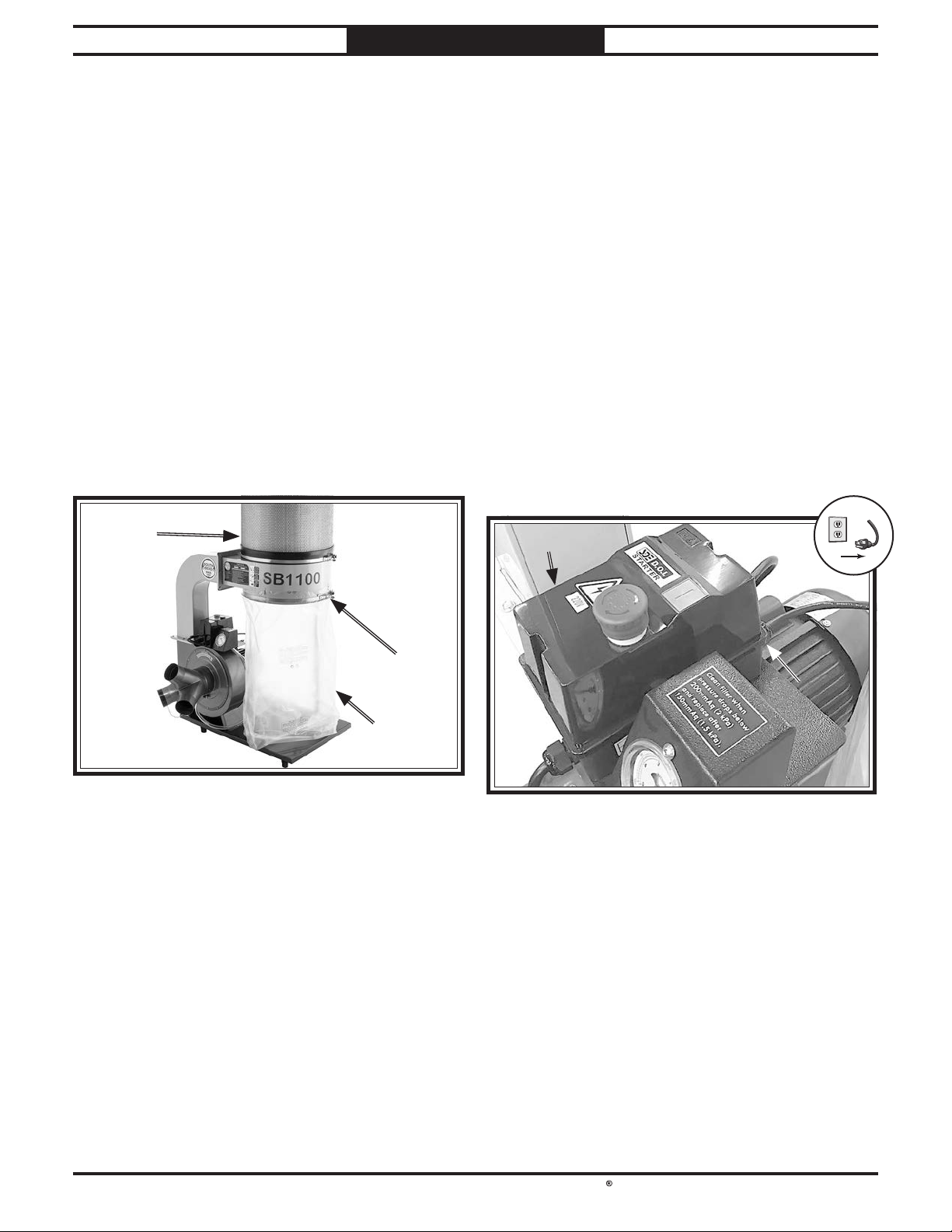
South Bend Tools
For Machines Mfd. Since 05/21 Model SB1100 & SB1101
!
MAINTENANCE
Removing/Replacing Collection Bag
Remove and replace the collection bag when it is
about
Items Needed Qty
T20543 Filter Bag ................................................. 1
To remove & replace filter bag or bags:
1. DISCONNECT MACHINE FROM POWER!
2.
IMPORTANT: To contain wood dust and
1
⁄2 full.
Release bag clamp around bottom of canister
filter, then remove filter bag (see Figure 66).
minimize risk of exposure, tie bag closed
before disposal.
CanisterCanister
FilterFilter
Removing/Replacing Canister Filter
If the canister filter is clogged or dirty and
cleaning does not improve dust-collection
performance, the canister filter must be replaced.
Items Needed Qty
An Assistant .......................................................... 1
Safety Glasses (Per Person)
Phillips Screwdriver #2
Wrench or Socket, 10mm
SB1487 Replacement Canister Filter
To remove & replace canister filter:
1. DISCONNECT MACHINE FROM POWER!
Remove front cover from switch box and
2.
loosen strain relief (see Figure 67).
Front CoverFront Cover
..................................1
........................................1
...................................... 1
.. As Needed
Bag ClampBag Clamp
CollectionCollection
Figure 66. Filter bag components. Filter bag components.
Attach new filter bag around bottom of
3.
canister filter and secure with clamp.
StrainStrain
ReliefRelief
BagBag
Figure Figure 67. Switch box front cover.. Switch box front cover.
-37-
Page 41
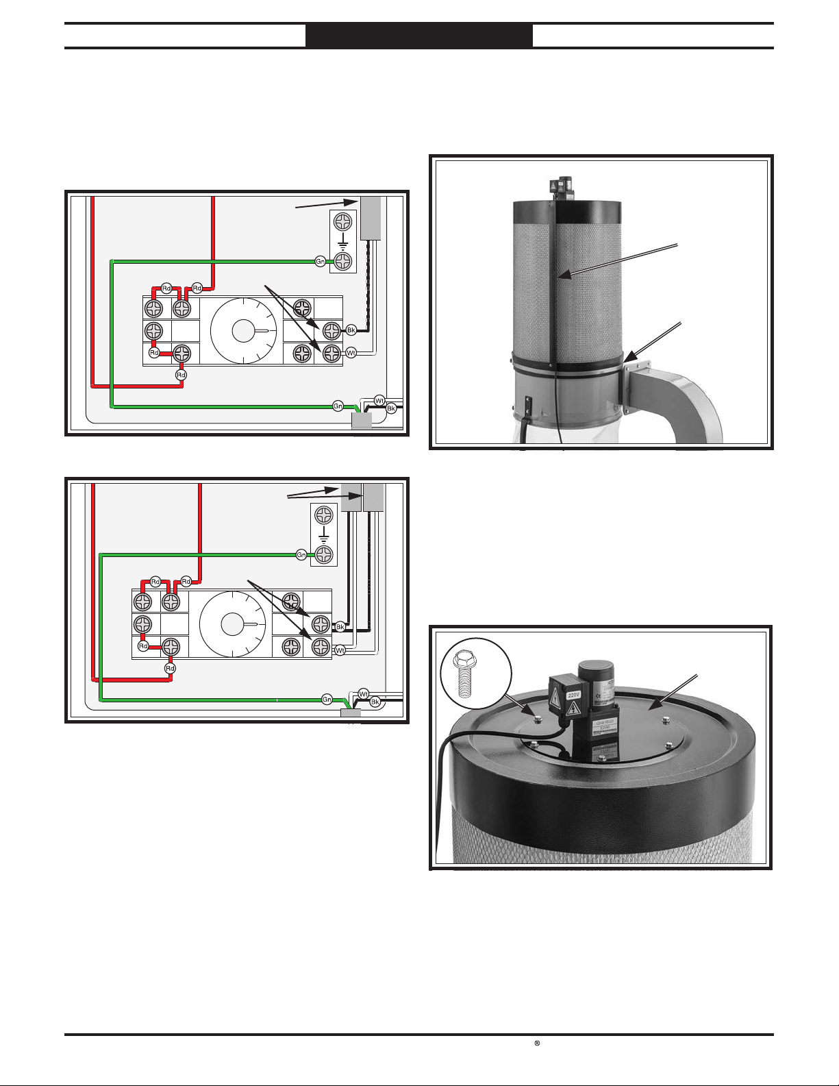
South Bend Tools
Model SB1100 & SB1101
MAINTENANCE
For Machines Mfd. Since 05/21
3. Disconnect motor cord(s) from right
terminals of timer inside switch box (see
Figures 68–69).
Note: Timer module may be pulled off
terminal block if it is in the way.
Motor Cord
Ground
Disconnect
14
12
13
9 5 1
0
3
Timer
Figure Figure 68. SB1100 filter brush motor connection.. SB1100 filter brush motor connection.
8
1
2
H3Y 5A 250VAC
4
4. Pull end of motor cord out of cord routing
cover (see Figure 70).
5. Release canister clamp (see Figure 70).
Cord RoutingCord Routing
CoverCover
Canister Canister
ClampClamp
Figure 70. Canister filter components. Canister filter components.
Motor Cords
Ground
Disconnect
14
12
13
9 5 1
0
3
Timer
8
1
2
H3Y 5A 250VAC
4
Figure Figure 69. SB1101 filter brush motor connection.. SB1101 filter brush motor connection.
Note: For full wiring diagrams, refer to SB1100
Wiring Diagram on Page 45 and SB1101 Wiring
Diagram on Page 48.
6. While assistant holds collector in place,
remove canister filter from collector.
Vacuum loose dust from collector.
7.
8. Remove (6) flange bolts and filter cover
assembly (see Figure 71).
Filter Filter
x6x6
Figure 71. Filter cover. Filter cover.
CoverCover
-38-
Page 42
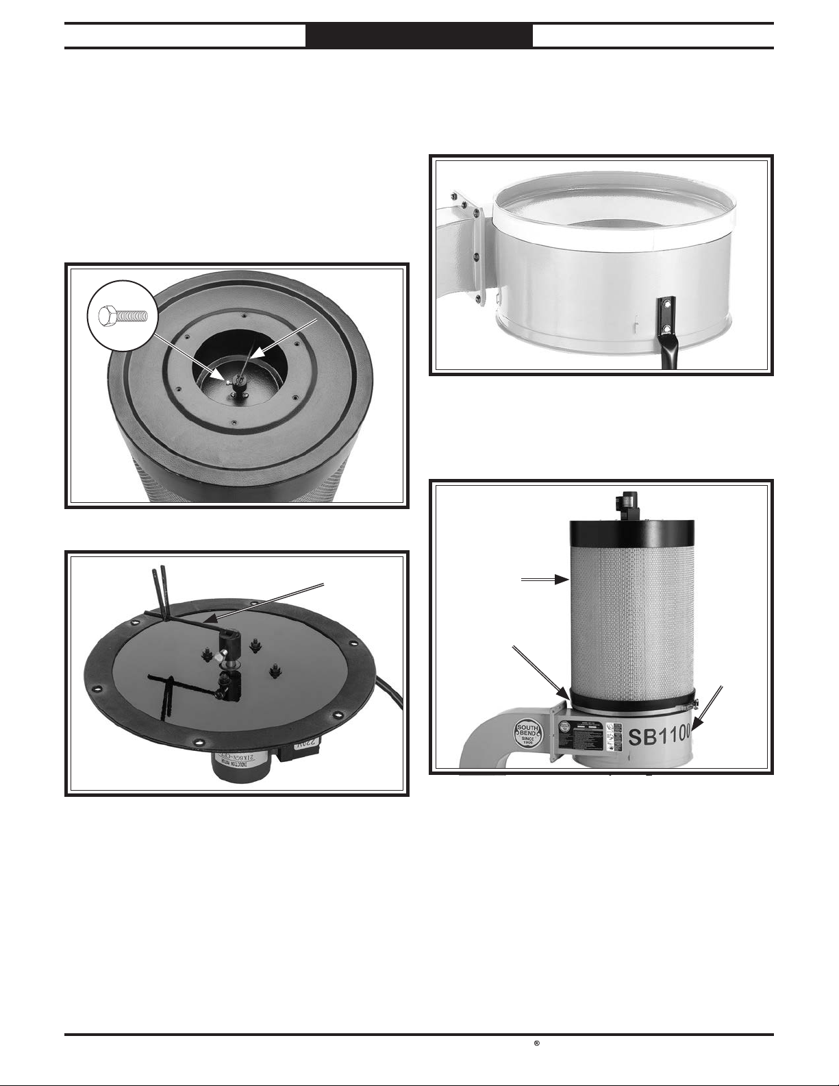
South Bend Tools
For Machines Mfd. Since 05/21 Model SB1100 & SB1101
MAINTENANCE
9. Loosen hex bolt and remove lower alignment
arm from filter brush spindle (see Figure
72), then attach lower alignment arm to new
canister filter.
10. Position filter cover assembly over new
canister filter. Rotate lower alignment arm
so "V" on upper alignment arm captures
lower arm when mounting holes align (see
Figures 72–73).
Lower Lower
Alignment ArmAlignment Arm
Mounting Mounting
HolesHoles
Inspect foam tape on upper rim of collector
12.
and replace if worn or dirty. Trim excess
tape so ends meet evenly without overhang
or gap (see Figure 74).
Figure Figure 74. Tape applied to top rim of collector.. Tape applied to top rim of collector.
13. Position canister clamp around base of
canister filter, then place canister filter over
collector (see Figure 75). Tighten clamp.
Figure 72. Top of canister and lower alignment arm. Top of canister and lower alignment arm.
Upper Upper
Alignment Alignment
ArmArm
Figure 73. Underneath filter cover assembly. Underneath filter cover assembly.
11. Attach filter cover assembly to canister filter
with flange bolts removed in Step 8.
Canister Canister
FilterFilter
CanisterCanister
ClampClamp
CollectorCollector
Figure Figure 75. Canister filter secured to collector with Canister filter secured to collector with
canister clamp.canister clamp.
-39-
Page 43
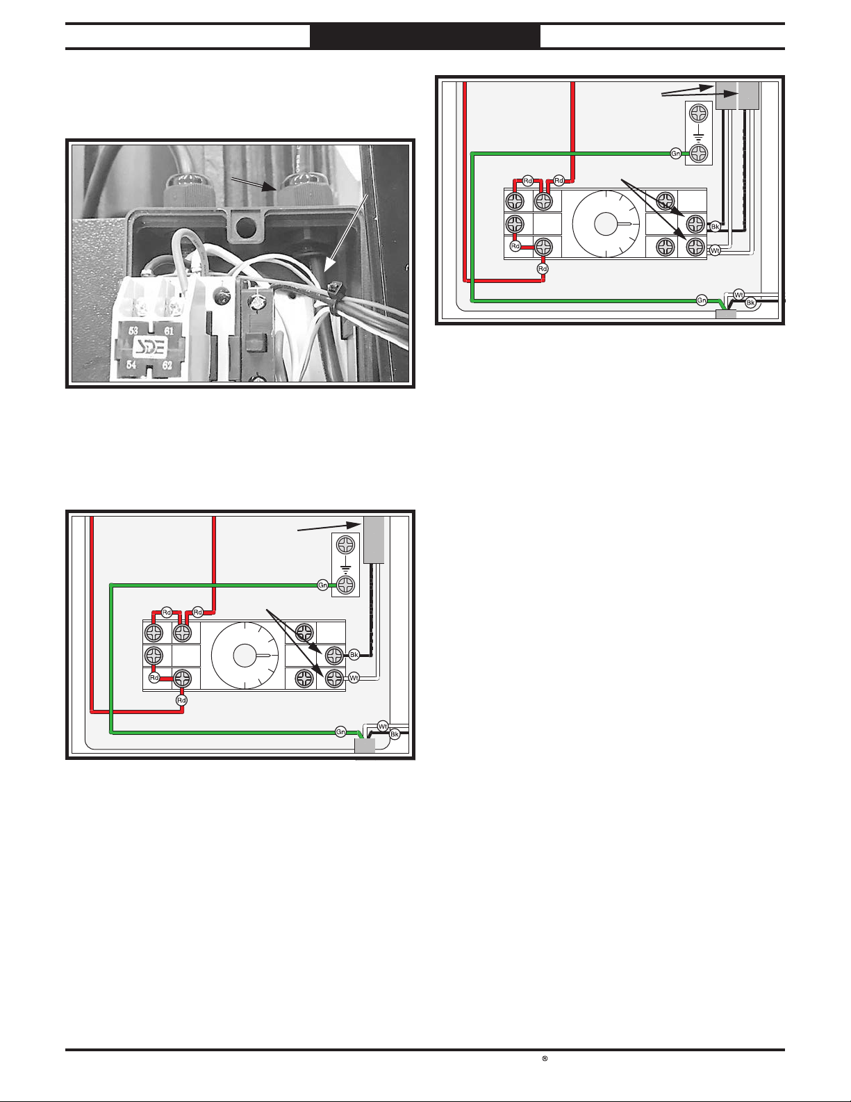
South Bend Tools
Model SB1100 & SB1101
MAINTENANCE
For Machines Mfd. Since 05/21
14. Push filter brush motor power cord through
cord routing cover and through strain relief
at top of switch box (see Figure 76).
StrainStrain
ReliefRelief
Figure Figure 76. Filter brush motor cord routed into switch . Filter brush motor cord routed into switch
box.box.
MotorMotor
CordCord
15. Connect motor terminal ends disconnected
in Step 3 to timer terminals (see Figures
77–78).
Motor Cords
Ground
Connect
14
12
13
9 5 1
0
3
Timer
8
1
2
H3Y 5A 250VAC
4
Figure Figure 78. SB1101 filter brush motor connection.. SB1101 filter brush motor connection.
Note: For full wiring diagrams, refer to SB1100
Wiring Diagram on Page 45 and SB1101 Wiring
Diagram on Page 48.
16. Tighten strain relief to secure motor cord(s)
and attach switch box cover to switch box.
Motor Cord
Ground
Connect
14
12
13
9 5 1
0
3
Timer
8
1
2
H3Y 5A 250VAC
4
Figure Figure 77. SB1100 filter brush motor connection.. SB1100 filter brush motor connection.
-40-
Page 44
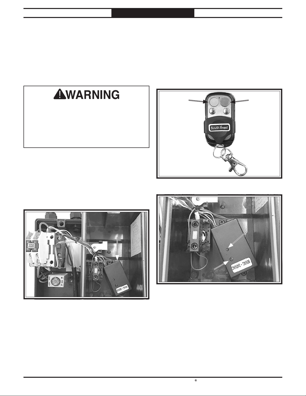
South Bend Tools
For Machines Mfd. Since 05/21 Model SB1100 & SB1101
SERVICE
SERVICE
Pairing Remote Control & Receiver
The Model SB1100 & SB1101 are equipped
with a remote control receiver that can be
programmed to operate up to 16 separate
controllers.
Avoid touching electrified parts inside receiver
while performing procedure below! Touching
electrified parts will result in personal injury
including but not limited to severe burns,
electrocution, or death. Use a wood dowel or
other non-conducting item to push button on
receiver.
Items Needed Qty
Phillips Head Screwdriver #2 ...............................1
Wood Dowel
........................................................... 1
2.
Press and hold green ON button on remote
control (see Figure 80) until LED indicator
illuminates on remote receiver (see Figure
81).
Press pairing button on receiver with a
3.
non-conducting tool, then release when LED
indicator turns off (see Figure 81). Pairing
is complete.
ON ButtonON Button OFF ButtonOFF Button
Pairing Remote
1. Remove switch cover to get a clear view of
remote receiver (see Figure 79).
ReceiverReceiver
Figure Figure 79. Location of receiver in switch box.. Location of receiver in switch box.
Figure Figure 80. Remote control.
LED LED
IndicatorIndicator
Pairing ButtonPairing Button
Figure Figure 81. Remote receiver.. Remote receiver.
Unpairing Remote
1. Remove switch cover to get a clear view of
remote receiver (see Figure 79).
Press and hold green ON button on remote
2.
control for eight seconds, then wait for LED
indicator to flash three times.
-41-
Page 45

South Bend Tools
Model SB1100 & SB1101
TROUBLESHOOTING
TROUBLESHOOTING
For Machines Mfd. Since 05/21
If you need replacement parts, or if you are unsure how to do any of the solutions given here, feel free
to call us at (360) 734-1540.
Symptom Possible Cause Possible Solution
Machine does not
start or a breaker
trips immediately
after startup.
Machine stalls or is
underpowered.
1.
Dust collector not connected to
ducting.
2.
E-Stop button depressed/at fault.
3.
Machine circuit breaker tripped.
4.
Incorrect power supply voltage or
circuit size.
5.
Remote control not working.
6.
Remote receiver at fault.
7.
Power supply circuit breaker
tripped or fuse blown.
8.
Motor wires connected incorrectly.
9.
Start capacitor at fault.
10.
Contactor not energized/at fault.
11.
Wiring broken, disconnected, or
corroded.
12.
Power switch/circuit breaker at fault.
13.
Centrifugal switch adjustment/
contact points at fault.
14.
Motor or motor bearings at fault.
1.
Dust collection ducting problem.
2.
Collection bags full.
3.
Canister filter clogged/at fault.
4.
Dust collector too far from machine
or undersized for dust-collection
system.
5.
Motor overheated, tripping machine
circuit breaker.
6.
Run capacitor at fault.
7.
Extension cord too long.
8.
Contactor not energized/at fault.
9.
Centrifugal switch adjustment/
contact points at fault.
10.
Motor or motor bearings at fault.
1.
Connect dust collector to ducting (Page 23).
2.
Rotate E-Stop button to reset. Replace if at fault.
3.
Reset circuit breaker on switch.
4.
Ensure correct power supply voltage and circuit
size.
5.
Replace battery; stay in signal range.
6.
Inspect/replace if at fault.
7.
Ensure circuit is free of shorts. Reset circuit
breaker or replace fuse.
8.
Correct motor wiring connections.
9.
Test/replace if at fault.
10.
Test all legs for power; replace if necessary.
11.
Fix broken wires or disconnected/corroded
connections.
12.
Replace switch/circuit breaker.
13.
Adjust centrifugal switch/clean contact points.
Replace either if at fault.
14.
Replace motor.
1.
Clear blockages, seal leaks, use smooth wall duct,
eliminate bends, close other branches.
2.
Replace collection bags.
3.
Clean canister filter (Page 36); replace canister
filter after 1 year of regular use (Page 37).
4.
Move closer to machine/redesign ducting layout
(Page 23)/upgrade dust collector.
5.
Clean motor/let cool, and reduce workload. Reset
breaker.
6.
Test/repair/replace.
7.
Move machine closer to power supply; use shorter
extension cord.
8.
Test all legs for power; repair/replace if at fault.
9.
Adjust centrifugal switch/clean contact points.
Replace either if at fault.
10.
Replace motor.
1.
Machine has
excessive vibration
or noise.
Motor or component loose.
2.
Motor mount loose/broken.
3.
Motor fan rubbing on fan cover.
4.
Centrifugal switch is at fault.
5.
Impeller damaged, unbalanced, or loose.
6.
Motor bearings at fault.
-42-
1.
Inspect/replace damaged or missing bolts/nuts, and
retighten with thread-locking fluid.
2.
Tighten/replace.
3.
Fix/replace fan cover; replace loose/damaged fan.
4.
Adjust/replace centrifugal switch if available.
5.
Inspect/tighten/replace.
6.
Test by rotating shaft; rotational grinding/loose
shaft requires bearing replacement.
Page 46

South Bend Tools
For Machines Mfd. Since 05/21 Model SB1100 & SB1101
TROUBLESHOOTING
Symptom Possible Cause Possible Solution
Filter brush motor
does not start after
machine is powered
OFF.
Loud, repetitious
noise, or excessive
vibration coming
from dust collector
(non-motor
related).
Dust collector does
not adequately
collect dust
or chips; poor
performance.
1.
Motor connected incorrectly at
switch box.
2.
Timer at fault.
3.
Filter brush motor at fault.
1.
Dust collector not on a flat surface
and wobbles/casters not locked.
2.
Impeller damaged and unbalanced.
3.
Impeller loose on the motor shaft.
1.
Collection bag(s) full.
2.
Canister filter clogged/at fault.
3.
Ducting blocked/restricted.
4.
Dust collector too far away from
point of suction; duct clamps not
properly secured; too many sharp
bends in ducting.
5.
Lumber is wet and dust is not
flowing smoothly through ducting.
6.
Ducting has one or more leaks, or
too many open ports.
7.
Not enough open branch lines at
one time, causing velocity drop in
main line.
8.
Ducting and ports are incorrectly
sized.
9.
Machine dust-collection design
inadequate.
10.
Dust collector undersized.
11.
Unused inlet adapter port(s)
uncovered.
1.
Correct motor wiring connections (Page 37).
2.
Inspect/replace if at fault.
3.
Replace motor.
1.
Stabilize dust collector; lock casters.
2.
Disconnect dust collector from power; inspect
impeller for dents, bends, or loose fins; replace
impeller if damaged.
3.
Secure impeller; replace motor and impeller as a set
if motor shaft and impeller hub are damaged.
1.
Empty collection bag(s) (Page 37).
2.
Clean canister filter (Page 36); replace canister
filter (Page 37).
3.
Remove ducting from dust collector inlet and
unblock restriction. A plumbing snake may be
necessary.
4.
Relocate dust collector closer to point of suction; resecure ducts; remove sharp bends (Page 23).
5.
Only process lumber with less than 20% moisture
content.
6.
Seal/eliminate all ducting leaks; close dust ports for
lines not being used (Page 23).
7.
Open 1 or 2 more blast gates to different branch
lines to increase main line velocity.
8.
Install correctly sized ducts and fittings (Page 23).
9.
Use dust-collection hood on stand.
10.
Install larger dust collector.
11.
Cover unused inlet adapter port(s).
1.
Dust collector
blows sawdust into
the air.
Remote control
does not operate
dust collector.
Duct clamps or filter collection bag
not properly clamped and secured;
ducting loose/damaged.
2.
Cylinder or funnel seals are loose or
damaged.
1.
Emergency Stop button is pressed in.
2.
Machine is disconnected from
power.
3.
Remote control battery is weak or
dead.
4.
Wall or barrier disrupts radio
frequency, or controller is too far
away.
5.
Remote control not paired with
receiver.
1.
Secure ducts and filter collection bag, making
sure duct and bag clamp are tight; tighten/replace
ducting.
2.
Tighten all mounting and sealing points; replace
damaged seals/gaskets.
1.
Rotate Emergency Stop button to reset.
2.
Verify machine is connected to power source.
3.
Replace battery.
4.
Move machine away from barrier; use remote
within 50' of machine.
5.
Program receiver to accept remote control (Page 41).
-43-
Page 47

South Bend Tools
Model SB1100 & SB1101
Shock Hazard: It is extremely dangerous to
Wire Connections:
Modifications:
Motor Wiring:
junction box.
Circuit Requirements: Connecting the machine
power inverters store an electrical charge for
our Technical Support at (360) 734-1540.
ELECTRICAL
ELECTRICAL
For Machines Mfd. Since 05/21
Electrical Safety Instructions
These pages are accurate at the time of printing. In the constant effort to improve, however, we may
make changes to the electrical systems of future machines. Study this section carefully. If you see
differences between your machine and what is shown in this section, call Technical Support at (360)
734-1540 for assistance BEFORE making any changes to the wiring on your machine.
perform electrical or wiring tasks while the
machine is connected to the power source.
Touching electrified parts will result in
personal injury including but not limited to
severe burns, electrocution, or death. For
your own safety, disconnect machine from
the power source before servicing electrical
components or performing any wiring tasks!
All connections must be
tight to prevent wires from loosening during
machine operation. Double-check all wires
disconnected or connected during any wiring
task to ensure tight connections.
Using aftermarket parts or
modifying the wiring beyond what is shown
in the diagram may lead to unpredictable
results, including serious injury or fire.
The motor wiring shown in these
diagrams is current at the time of printing,
but it may not match your machine. Always
use the wiring diagram inside the motor
to an improperly sized circuit will greatly
increase the risk of fire. To minimize
this risk, only connect the machine to a
power circuit that meets the minimum
requirements given in this manual.
Capacitors/Inverters: Some capacitors and
up to 10 minutes after being disconnected
from the power source. To reduce the risk of
being shocked, wait at least this long before
working on capacitors.
Wire/Component Damage: Damaged wires
or components increase the risk of serious
personal injury, fire, or machine damage. If
you notice that any wires or components are
damaged while performing a wiring task,
replace those wires or components before
completing the task.
Experiencing Difficulties: If you are
experiencing difficulties understanding the
information included in this section, contact
BLACK
BLUE
BROWN
NOTICE:
-44-
WIRING DIAGRAM COLOR KEY
BLUE
WHITE
GREEN
G R AY
The photos and diagrams included in this section are best viewed in color. You can
see them in color at www.southbendtools.com.
RED
LIGHT
BLUE
ORANGE
PINK
PURPLE
TURQUIOSE
WHITE
YEL LOW
GREEN
YEL LOW
Page 48
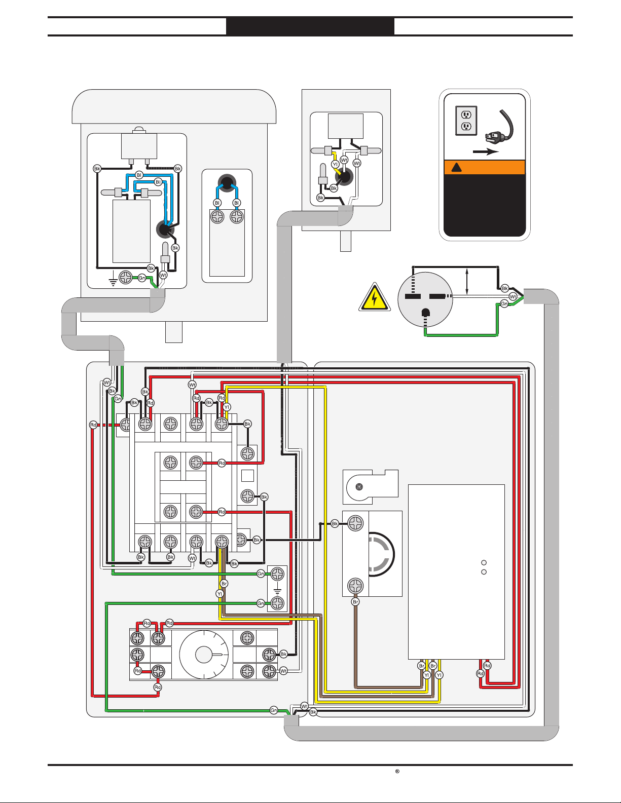
South Bend Tools
For Machines Mfd. Since 05/21 Model SB1100 & SB1101
ELECTRICAL
SB1100 Wiring Diagram
Filter Brush
Main Motor 220V
Circuit
Breaker
KUOYUH 88 Series
15A 250 VAC
Load Line
Run
Capacitor
30 µF
250 VAC
Start
Capacitor
300 MFD
125 VAC
Motor 220V
Run
Capacitor
FJ 1.0 µF
450 VAC
6-15 Plug
G
!
!
WARNING!
SHOCK HAZARD!
Disconnect power
before working
on wiring.
Hot
220
VAC
Hot
Ground
1
L1/1 L3/5
L2/3
Contactor
SDE
MA-09
220V
T1/2 T3/6
T2/4
14
12
13
Switch Box Switch Box Cover
7
53 61
Aux Contactor
AP2-11
54 62
8
Ground
0
9 5 1
3
8
1
2
4
Start
Button
HY57B
E-Stop
Button
Switch
Remote Receiver
Reset
Timer
H3Y 5A 250VAC
-45-
Page 49
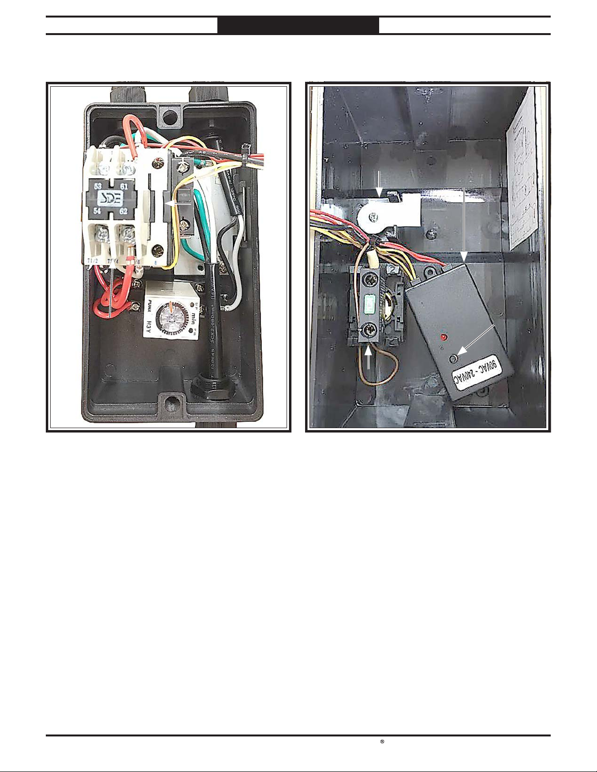
South Bend Tools
Model SB1100 & SB1101
ELECTRICAL
For Machines Mfd. Since 05/21
SB1100 Electrical Component Pictures
To Main To Main
MotorMotor
AuxiliaryAuxiliary
ContactorContactor
To Filter Brush To Filter Brush
MotorMotor
ContactorContactor
TimerTimer
Start ButtonStart Button
Remote ReceiverRemote Receiver
Remote ResetRemote Reset
ButtonButton
EmergencyEmergency
Stop ButtonStop Button
Power Power
CordCord
Figure Figure 82. SB1100 switch box interior. Figure Figure 83. SB1100 switch box cover.
-46-
Page 50
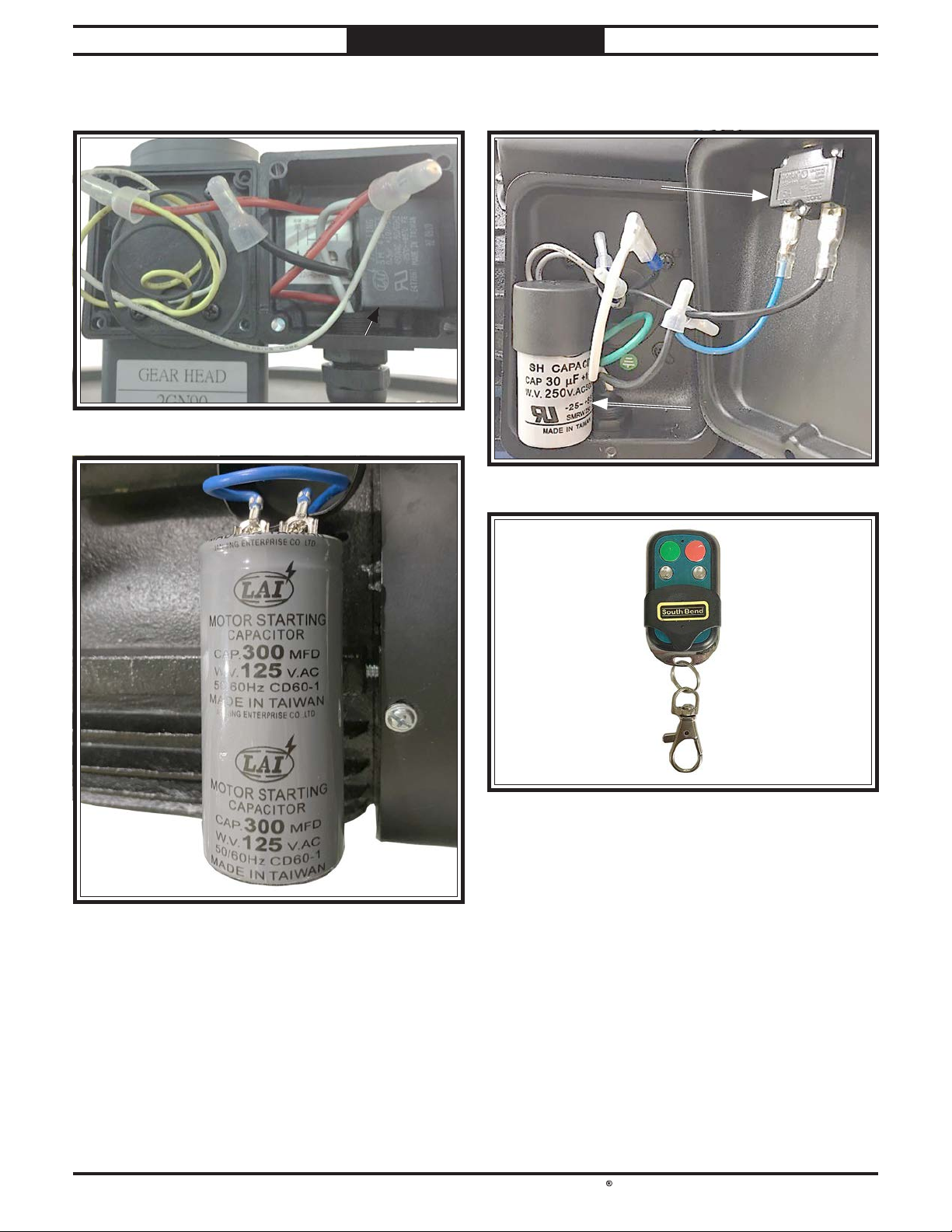
South Bend Tools
For Machines Mfd. Since 05/21 Model SB1100 & SB1101
ELECTRICAL
SB1100 Electrical Component Pictures (Cont.)
CircuitCircuit
BreakerBreaker
Run CapacitorRun Capacitor
Figure Figure 84. SB1100 filter brush motor junction box.
Run CapacitorRun Capacitor
Figure Figure 86. SB1100 main motor junction box.
Figure Figure 87. SB1100 remote.
Figure Figure 85. SB1100 start capacitor.
-47-
Page 51
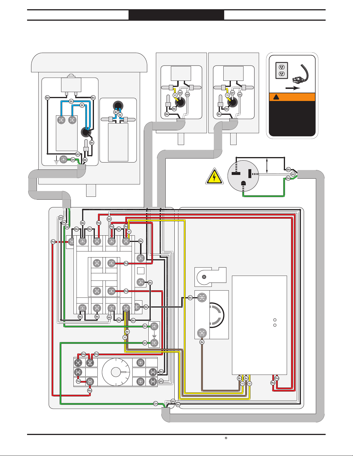
South Bend Tools
Model SB1100 & SB1101
ELECTRICAL
SB1101 Wiring Diagram
For Machines Mfd. Since 05/21
Main Motor 240V
Circuit
Breaker
KUOYUH 88 Series
18A 250 VAC
Load Line
Start
Capacitor
500 MFD
125 VAC
Switch Box Switch Box Cover
Run
Capacitor
40 µF
300 VAC
Filter Brush
Motor 240V
Run
Capacitor
FJ 1.0 µF
450 VAC
Filter Brush
Motor 240V
Run
Capacitor
FJ 1.0 µF
450 VAC
G
6-20 Plug
240
VAC
Hot
Ground
!
!
WARNING!
SHOCK HAZARD!
Disconnect power
before working
on wiring.
Hot
1
L1/1 L3/5
L2/3
Contactor
SDE
MA-09
53 61
Aux Contactor
220V
54 62
T1/2 T3/6
T2/4
14
12
13
9 5 1
AP2-11
0
3
Timer
7
8
Ground
8
1
2
H3Y 5A 250VAC
Start
Button
Remote Receiver
HY57B
Reset
E-Stop
Button
Switch
4
-48-
Page 52
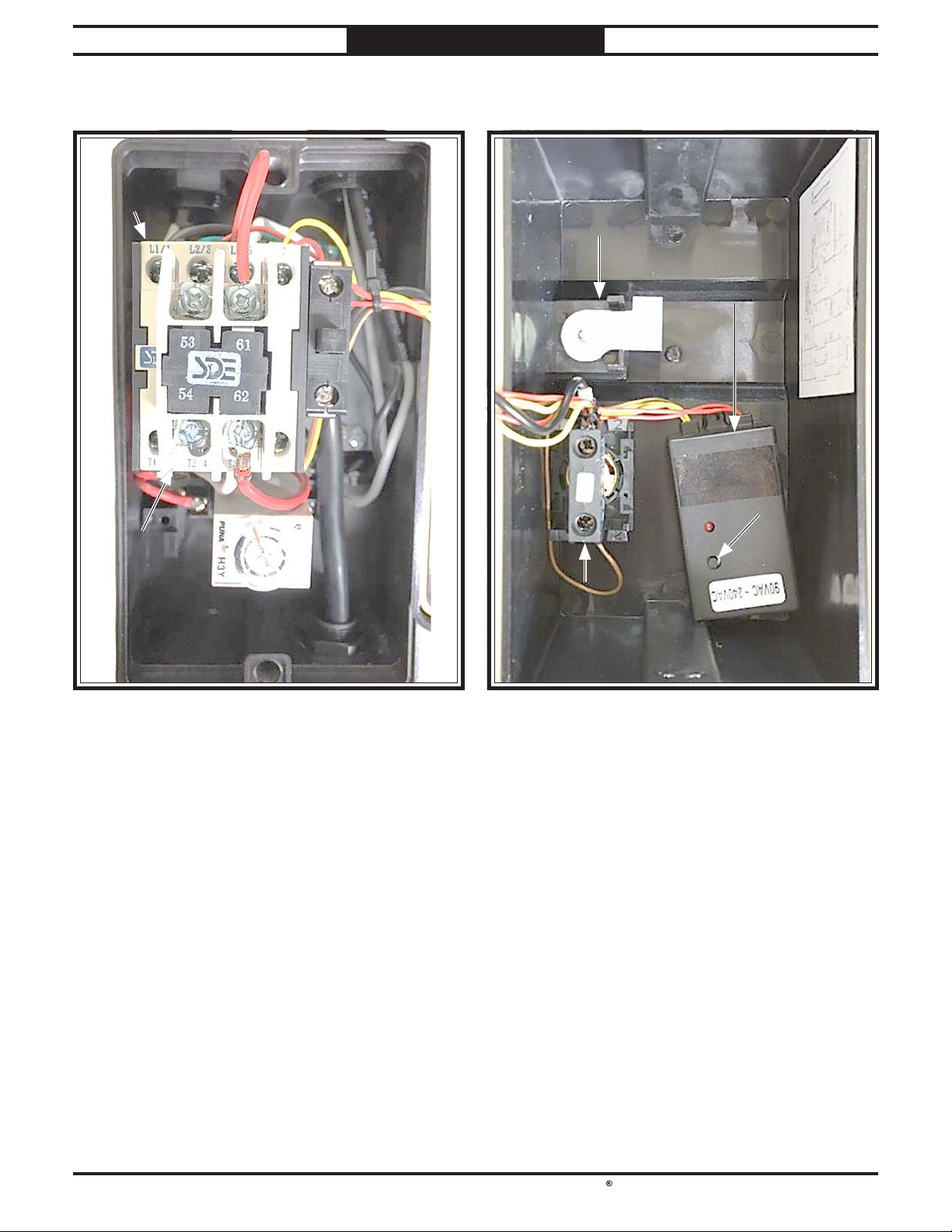
South Bend Tools
For Machines Mfd. Since 05/21 Model SB1100 & SB1101
ELECTRICAL
SB1101 Electrical Component Pictures
ContactorContactor
AuxiliaryAuxiliary
ContactorContactor
To Main To Main
MotorMotor
To Filter Brush To Filter Brush
MotorMotor
Start ButtonStart Button
Remote ReceiverRemote Receiver
Remote ResetRemote Reset
ButtonButton
TimerTimer
EmergencyEmergency
Stop ButtonStop Button
Power Power
CordCord
Figure Figure 88. SB1101 switch box interior. Figure Figure 89. SB1101 switch box cover.
-49-
Page 53
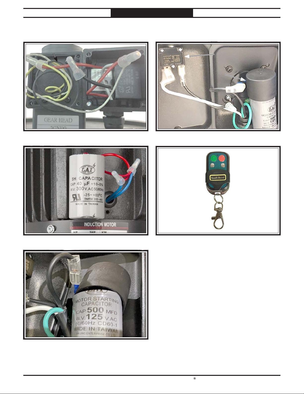
South Bend Tools
Model SB1100 & SB1101
ELECTRICAL
For Machines Mfd. Since 05/21
SB1101 Electrical Component Pictures (Cont.)
Run CapacitorRun Capacitor
Figure Figure 90. SB1101 filter brush motor junction box.
CircuitCircuit
BreakerBreaker
Start Start
CapacitorCapacitor
Figure Figure 93. SB1101 main motor junction box.
-50-
Figure Figure 91. SB1101 run capacitor.
Figure Figure 92. SB1101 start capacitor.
Figure Figure 94. SB1101 remote.
Page 54
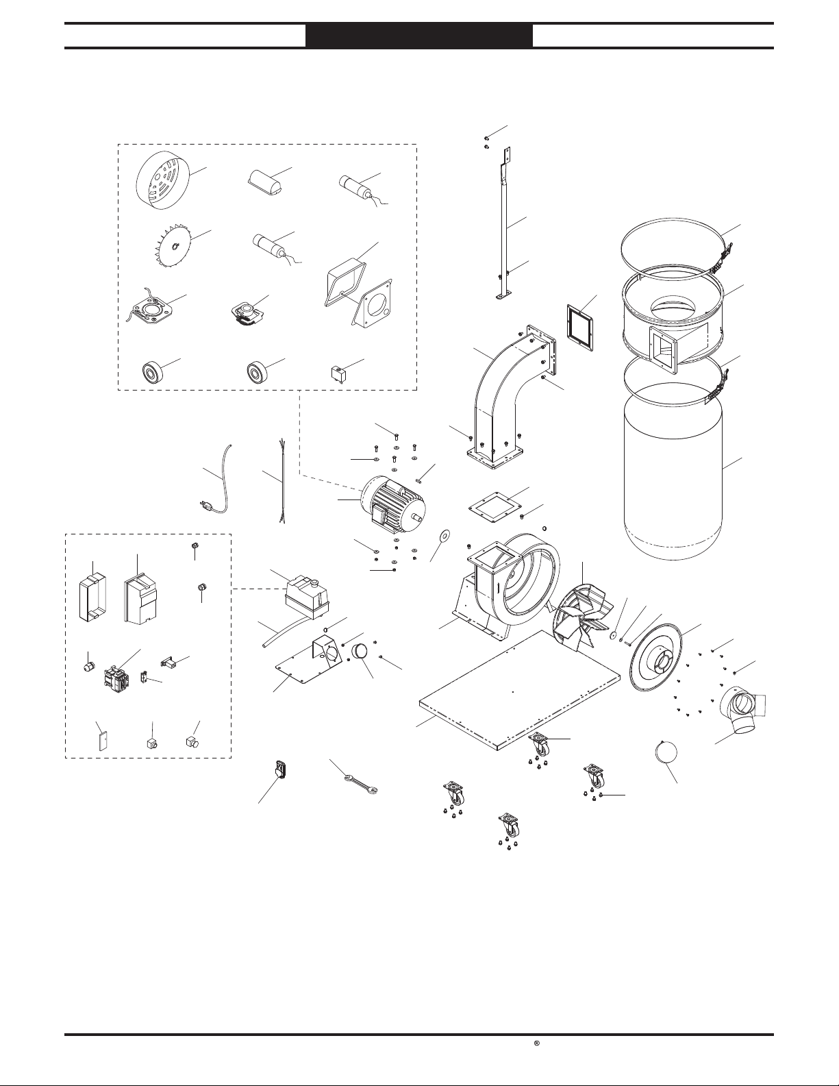
South Bend Tools
For Machines Mfd. Since 05/21 Model SB1100 & SB1101
PARTS
PARTS
SB1100 Main
7
27V2-1
27V2-5
27V2-9
27V2-2
27V2-6
27V2-10
37-6
35
27V2-3
27V2-4
27V2-8
27V2-7
27V2-11
37-1
37-4
34
27V2
33
28
37-7
37-10
37-2
37-5
37
25
20
20
22
32
21
37-1137-9
31
37-3
37-8
29
30
1
16
12
24
17
7
15
11
7
7
15
7
13
9
26
10
18
4
36
3
2
8
5
14
19
38V2
7
6
-51-
Page 55

South Bend Tools
Model SB1100 & SB1101
PARTS
For Machines Mfd. Since 05/21
SB1100 Parts List
REF PART # DES CRIPT IO N REF PART # DESCRIPTIO N
1 PSB1100001 BASE 27V2-5 PSB1100027V2-5 STRAIN RELIEF TYPE-3 M30
2 PSB1100002 BAG CLAMP 500MM 27V2-6 PSB1100027V2-6 CONTACTOR SDE MA-09 220V
3 PSB1100003 COLLECTOR 27V2-7 PSB1100027V2-7 AUX CONTACTOR SDE AP2-11
4 PSB1100004 IN LET ADAPTER 6 " X 4" X 3 27V2-8 PSB1100027V2-8 TIMER PUN A H3Y-2 240 V
5 PSB1100005 HOUSIN G COVER 27V2-9 PSB1100027V2-9 REMOTE CON TROL RECEIVER
6 PSB1100006 INLET CA P 4" 27V2-10 PSB1100027V2-10 BUTTON SDE CP GRN
7 PSB1100007 FLANGE BOLT 5/16-18 X 1/2 27V2-11 PSB1100027V2-11 E-STOP BUTTON SDE HY57B 22MM
8 PSB1100008 FILTER BAG 28 PSB1100028 GAUGE BRACKET
9 PSB1100009 IMPELLER WASHER 29 PSB1100029 P RESSURE GA UGE
10 PSB1100010 CAP SCREW M6-1 X 30 LH 30 PSB1100030 B UTTON H D CAP SCR 1/4-20 X 1/2
11 PSB1100011 L-SH APE OUTLET TUB E 31 PSB1100031 HEX N UT 1/4-20
12 PSB1100012 IMPELLER HOUSIN G 32 PSB1100032 HOSE CLAMP 3/4"
13 PSB1100013 IMPELLER 12-3/4" 33 PSB1100033 HOSE 1/2"
14 PSB1100014 PHLP HD SCR 10-24 X 3/8 34 PSB1100034 MOTOR CORD 1 4G 3W 2 6"
15 PSB1100015 SQUARE GASKET 35 PSB1100035 POWER CORD 14G 3W 65" 6 -1 5P
16 PSB1100016 MOTOR GAS KET 36 PSB1100036 CANISTER CLAMP 520MM
17 PSB1100017 CA NISTER SUPPORT 37 PSB1100037 MOTOR 2HP 220V 1-PH
18 PSB1100018 CASTER 2-1/2", SWIVEL 37-1 PSB1100037-1 MOTOR FAN COVER
19 PSB1100019 PHLP HD SCR 10-24 X 3/8 37-2 PSB1100037-2 CAPACITOR COVER
20 PSB1100020 FEN DER WASHER 5/16 37-3 PSB1100037-3 S CAPAC ITOR 30 0M 1 25V 1-3/4 X 3-1 /2
21 PSB1100021 HEX BOLT 5/16-18 X 1 37-4 PSB1100037-4 MOTOR F AN
22 PSB1100022 HEX NUT 5/16-18 37-5 PSB1100037-5 R CAPACITOR 30M 250V 1-3/8 X 2-3/8
24 PSB1100024 KEY 7 X 7 X 25 37-6 PSB1100037-6 CONTA CT PLATE
25 PSB1100025 WRENCH 10 X 12MM OPEN-ENDS 37-7 PSB1100037-7 CEN TRIFUGAL SWITCH
26 PSB1100026 LOCK WASHER 1/4 37-8 PSB1100037-8 J UNCTION BOX
27V2 PSB1100027V2 MAGNETIC SWITCH SDE MP-30 220V V2.05.21 37-9 PSB1100037-9 FRONT MOTOR BEARING 6205ZZ
27V2-1 PSB1100027V2-1 MA G SWITCH REAR COVER 37-10 PSB1100037-10 REAR M OTOR BEA RIN G 620 3ZZ
27V2-2 PSB1100027V2-2 MA G SWITCH F RONT C OVER 37-11 PSB1100037-11 CIRCUIT BREAKER 15A KUOYUH 88 SERIES
27V2-3 PSB1100027V2-3 STRAIN RELIEF TYPE-3 M16 38 V2 PSB1100038V2 REMOTE V2.05.21
27V2-4 PSB1100027V2-4 STRAIN RELIEF TYPE-3 M20
-52-
Page 56
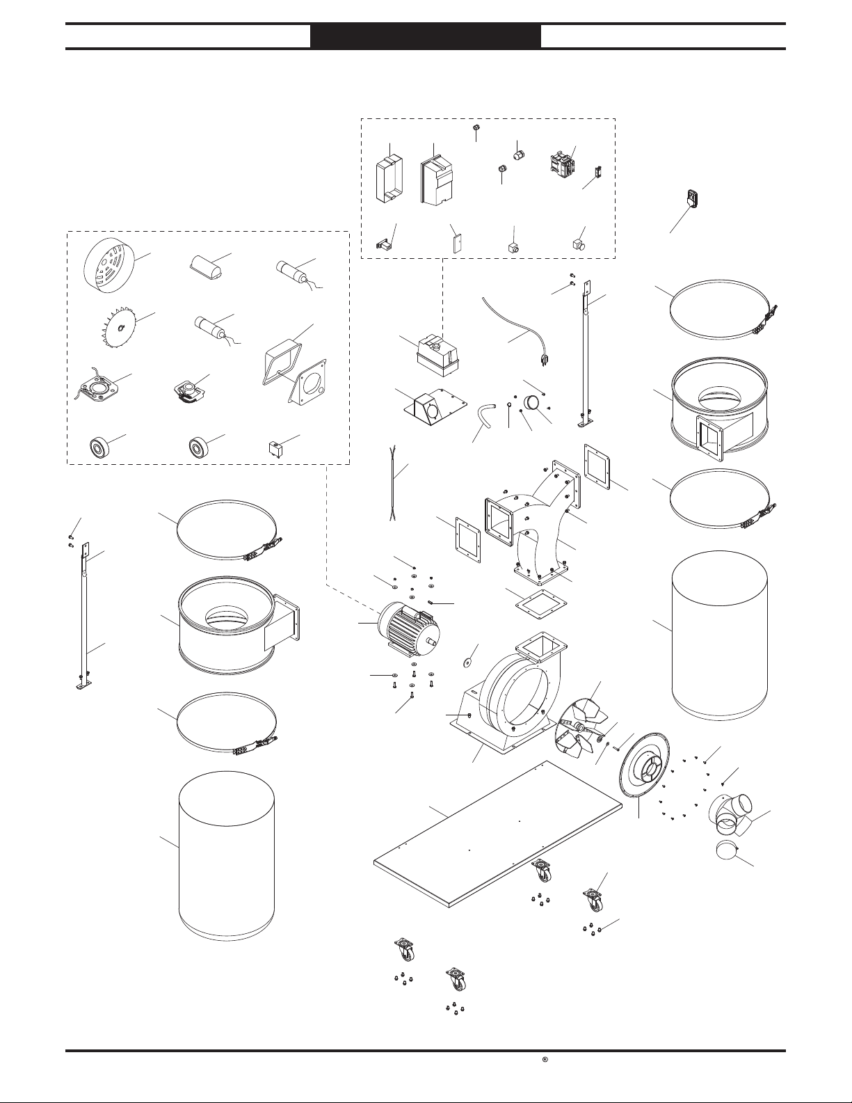
South Bend Tools
For Machines Mfd. Since 05/21 Model SB1100 & SB1101
PARTS
SB1101 Main
22
21
3
30-6
30-1
30-4
36
17
30-7
30-10
30-2
30-5
30-3
30-1130-9
30-8
30
27V2-1
6
27V2-8
27V2
28
7
27V2-2
37
15
27V2-3
27V2-9
34
24
27V2-4
27V2-10
38
15
8
27V2-5
31
33
22
32
27V2-6
27V2-7
27V2-11
29
3
20
39V2
36
21
16
18
15
3
19
18
19
6
5
3
4
1
26
9
10
11
12
2
3
13
35
14
23
-53-
Page 57
South Bend Tools
Model SB1100 & SB1101
PARTS
For Machines Mfd. Since 05/21
SB1101 Parts List
REF PART # DESCRIPTION REF PART # DES CRIPTIO N
1 PSB1101001 BASE 27V2-5 PSB1101027V2-5 STRAIN RELIEF TYPE-3 M30
2 PSB1101002 CASTER 2-1/2", SWIVEL 27V2-6 PSB1101027V2-6 CONTACTOR SDE MA-09 220V
3 PSB1101003 FLANGE BOLT 5/16-18 X 1/2 27V2-7 PSB1101027V2-7 AUX CON TACTOR SDE AP2-1 1
4 PSB1101004 IMPELLER H OUSIN G 27V2-8 PSB1101027V2-8 TIMER PUNA H3Y-2 240V
5 PSB1101005 HEX BOLT 5/16-18 X 1 27V2-9 PSB1101027V2-9 REMOTE CONTROL RECEIVER
6 PSB1101006 FEN DER WASHER 5/16 27V2-10 PSB1101027V2-10 BUTTON SDE CP GRN
7 PSB1101007 HEX NUT 5/16-18 27V2-11 PSB1101027V2-11 E-STOP B UTTON SDE HY57B 22MM
8 PSB1101008 MOTOR GASKET 28 PSB1101028 GAUGE BRACKET
9 PSB1101009 IMPELLER 12-3/4" 29 PSB1101029 P RESSURE GA UGE
10 PSB1101010 IMPELLER WASH ER 30 PSB1101030 M OTOR 3H P 220V 1-P H
11 PSB1101011 CAP SCREW M6-1 X 30 LH 30-1 PSB1101030-1 MOTOR F AN COVER
12 PSB1101012 H OUSIN G COVER 30-2 PSB1101030-2 CAPACITOR COVER
13 PSB1101013 PHLP HD SCR 10-24 X 3/8 30-3 PSB1101030-3 R CAPACITOR 40M 300V 1-1/2 X 2-3/4
14 PSB1101014 IN LET ADAPTER 7" X 4" X 3 30-4 PSB1101030-4 M OTOR F AN
15 PSB1101015 SQUARE GASKET 30-5 PSB1101030-5 S CAPACITOR 500M 125V 1-3/8 X 2-5/8
16 PSB1101016 RIGHT COLLECTOR 30-6 PSB1101030-6 CONTACT PLA TE
17 PSB1101017 LEFT COLLECTOR 30-7 PSB1101030-7 CENTRIFUGAL SWITCH
18 PSB1101018 BAG CLAMP 500MM 30 -8 PSB1101030-8 J UN CTION B OX
19 PSB1101019 FILTER B AG 30-9 PSB1101030-9 FRONT MOTOR BEARING 620 5ZZ
20 PSB1101020 Y-S HAPE OUTLET TUBE 30-10 PSB1101030-10 REAR MOTOR BEARIN G 6203ZZ
21 PSB1101021 CA NISTER SUPPORT 30 -11 PSB1101030-11 CIRCUIT BREAKER 18A KUOYUH 88 SERIES
22 PSB1101022 FLA NGE BOLT 5/1 6-1 8 X 3/4 31 PSB1101031 BUTTON HD CAP S CR 1 /4-20 X 1/2
23 PSB1101023 IN LET CA P 4" 32 PSB1101032 H EX N UT 1/4-20
24 PSB1101024 KEY 7 X 7 X 25 33 PSB1101033 HOSE CLAMP 3/4"
26 PSB1101026 LOCK WASHER 1/4 34 PSB1101034 HOSE 1/2"
27V2 PSB1101027V2 MAGNETIC SWITCH SDE MP-30 220V V2.05.21 35 PSB1101035 PHLP HD SCR 10-24 X 3/8
27V2-1 PSB1101027V2-1 MA G SWITCH REAR COVER 36 PSB1101036 CANISTER CLAMP 520MM
27V2-2 PSB1101027V2-2 M AG SWITCH FRON T COVER 37 PSB1101037 M OTOR C ORD 14G 3W 26"
27V2-3 PSB1101027V2-3 STRAIN RELIEF TYPE-3 M1 6 38 PSB1101038 POWER C ORD 14G 3W 64" 6-2 0P
27V2-4 PSB1101027V2-4 S TRAIN RELIEF TYPE-3 M20 39V2 PSB1101039V2 REMOTE V2.05.21
-54-
Page 58
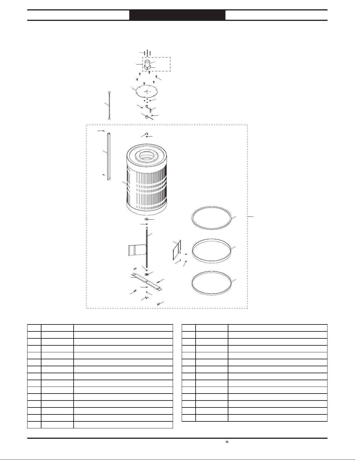
South Bend Tools
For Machines Mfd. Since 05/21 Model SB1100 & SB1101
124
PARTS
Canister Filter
123
126
104
105
103
121
125
102
115
120
120
108
106
121-1
121-2
122
111
101
125
110
119
118
105A
120
107
113
114
115
REF PART # DES CRIPT IO N REF PART # DES CRIPT IO N
101 PSB1100101 UPPER SPINDLE LEVER 115 PSB1100115 PHLP HD SCR M5-.8 X 8
102 PSB1100102 LOWER SPINDLE LEVER 116 PSB1100116 PHLP HD SCR M6-1 X 10
103 PSB1100103 FILTER COVER 117 PSB1100117 FOAM GASKET 20 X 1560MM
104 PSB1100104 CORD ROUTI NG COVER 118 PSB1100118 FOAM GASKET 42 X 1560MM
105A PSB1100105A CANISTER F ILTER A SSEMBLY 119 PSB1100119 FOAM GASKET 10 X 1560MM
105 PSB1100105 CAN ISTER FILTER 120 PSB1100120 THRUST B EARING 12 X 14 X 6 MM
106 PSB1100106 FILTER BRUS H SPINDLE 121 PSB1100121 F ILTER B RUSH MOTOR ASS EMBLY
107 PSB1100107 LOWER BRACKET 121-1 PSB1100121-1 MOTOR 6W 220V 1 -PH
108 PSB1100108 BEARING FIXING PLATE 121-2 PSB1100121-2 GEAR REDUCER 2GN 90
109 PSB1100109 SUPPORT TAB 122 PSB1100122 FLA NGE BOLT 1/4-20 X 3/4
110 PSB1100110 PADDLE B RUSH 123 PSB1100123 PHLP HD SCR M5-.8 X 10
111 PSB1100111 HEX N UT M5-.8 124 PSB1100124 CA P SCREW M5-.8 X 50
112 PSB1100112 PHLP HD SCR M6-1 X 12 125 PSB1100125 HEX BOLT M6-1 X 16
113 PSB1100113 FLAT WASHER 1/4 126 PSB1100126 MOTOR CORD 1 8G 2W 6 6"
114 PSB1100114 PHLP HD SCR M5-.8 X 15
108
116
113
109
114
112
117
-55-
Page 59
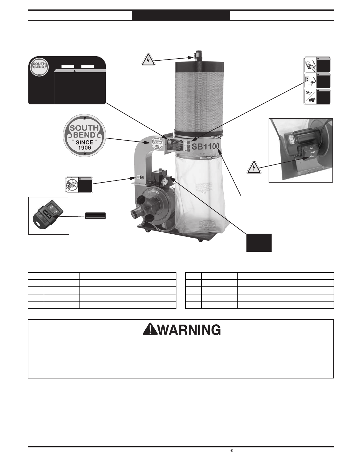
South Bend Tools
Model SB1100 & SB1101
201 202
203
Machine Labels
MODEL SB1100
SINCE
1906
Main Motor: 2 HP, 220V, 1-Ph, 60 Hz
Full-Load Current Rating: 9.15A
Airflow Performance: 1103 CFM @ 3.5" SP
Max. Static Pressure: 11.95"
Main Inlet Size: 6"
Adapter Inlet Size: 4"
Max. Collection Capacity: 33-1/2 Gallons
Cartridge Filter: 19-5/8" x 29"
Filter Rating: 1 Micron
Replacement Filter: SB1487
Replacement Bag: T20543
Weight: 157 lbs.
Made in Taiwan to South Bend Specifications
2 HP SINGLE-STAGE DUST COLLECTOR
WARNING!
To reduce the risk of serious injury when using this machine:
1. Read and understand owner’s manual before operating.
2. Always wear approved eye protection and respirator while operating machine.
3. Only plug power cord into a grounded outlet.
4. Only use this machine to collect wood dust/chips—never use to collect glass, metal,
5. Always disconnect power before servicing or cleaning.
6. Do not expose to rain or use in wet areas.
7. Keep hands, long hair, and loose clothing away from inlet.
8. Never leave machine unattended during operation.
9. Do not use if cord, plug, or any other electrical equipment becomes
10. Do not use without dust bag, canister, or filters in place.
11. Do not connect cord to power supply with wet hands.
12. Grasp and pull the plug, not the cord, when unplugging.
13. Always wear a respirator when emptying bags or canisters.
14. Do not modify machine in any way.
15. Prevent unauthorized use by children or untrained users; restrict access or disable
!
liquids, asbestos, silica, animal parts, biohazards, burning material/ashes, etc.
damaged—promptly repair!
machine when unattended.
208
MFG DateSerial No
PARTS
For Machines Mfd. Since 05/21
!
WARNING!
INJURY HAZARD
Do not use machine
if you have not read
the manual. Visit
southbendlathe.com
or call 360-734-1540
to get a manual.
!
WARNING!
INJURY/SHOCK
HAZARD
!
To avoid shock or
accidental starting,
disconnect power
before adjusting or
servicing machine.
!
WARNING!
EYE/LUNG INJURY
HAZARD
Always wear ANSIapproved safety
glasses and
respirator when
using this
equipment.
207
!
WARNING!
AMPUTATION
HAZARD
DO NOT place
hands near inlet
during operation!
206
South Bend
REF PART # DESCRIPTION REF PART # DES CRIPT IO N
®
201 PSB1100201 M ACHINE ID LABEL (SB1 10 0) 204 PSB1101204 M ODEL NUMBER LABEL (SB1 10 1)
201 PSB1101201 MACHINE ID LABEL (SB1101) 205 PSB1100205 VACUUM PRESSURE GAUGE LABEL
202 PSB1100202 ELECTRICITY LABEL 206 PSB1100206 REMOTE LABEL
203 PSB1100203 DUST COLLECTOR COM B O LABEL 207 PSB1100207 AMPUTATION HAZARD LABEL
204 PSB1100204 MODEL NUMB ER LABEL (SB 1100) 208 PSB1100208 SOUTH BEN D NAMEPLATE 125MM
The safety labels provided with your machine are used to make the operator aware of the
machine hazards and ways to prevent injury. The owner of this machine MUST maintain the
original location and readability of these safety labels. If any label is removed or becomes
unreadable, REPLACE that label before using the machine again. Contact South Bend Tools at
(360) 734-1540 or www.southbendtools.com to order new labels.
202
204
SB1100
205
Clean filter when
pressure drops below
200mmAq (2 kPa)
and replace after
150mmAq (1.5 kPa).
-56-
Page 60

WARRANTY
This quality product is warranted by South Bend Tools to the original buyer for 2 years from the
date of purchase. This warranty does not apply to consumable parts, or defects due to any kind of
misuse, abuse, negligence, accidents, repairs, alterations or lack of maintenance. We do not reimburse
for third party repairs. In no event shall we be liable for death, injuries to persons or property, or for
incidental, contingent, special or consequential damages arising from the use of our products.
We do not warrant or represent that this machine complies with the provisions of any law, act,
code, regulation, or standard of any domestic or foreign government, industry, or authority. In no
event shall South Bend’s liability under this warranty exceed the original purchase price paid for
this machine. Any legal actions brought against South Bend Tools shall be tried in the State of
Washington, County of Whatcom.
This is the sole written warranty for this machine. Any and all warranties that may be implied by
law, including any merchantability or fitness, for any purpose, are hereby limited to the duration of
this warranty.
Thank you for your business and continued support.
To take advantage of this warranty, register at
can scan the QR code below to be automatically directed to our warranty registration page. Enter all
applicable information for the product.
Warranty
https://www.grizzly.com/forms/warranty, or you
WARRANT Y
southbendtools.com
Page 61

southbendtools.com
Printed In U.S.A. #AI21261
 Loading...