

Page 1
IMPORTANT FOR FUTURE REFERENCE
Please complete this information and retain this
manual for the life of the equi pment:
Model #: __________________________
Serial #: __________________________
Date Purchased: ___________________
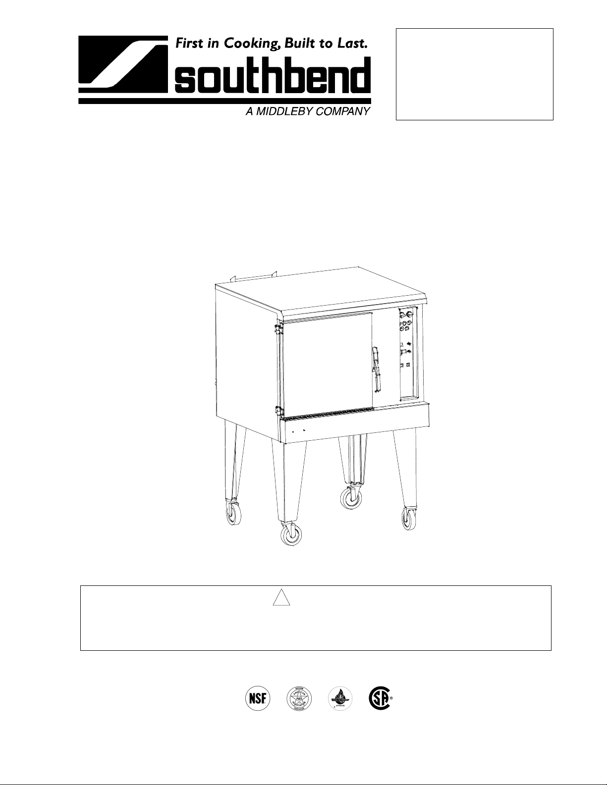
OPERATOR'S MANUAL
Combination (Combi) Oven
Model CG90-1
! WARNING
Improper installation, adjustment, alteration, service or maintenance can cause property damage,
injury or death. Read the installation, operating and maintenance instructions thoroughly before
installing or servicing this equipment.
1100 Old Honeycutt Road, Fuquay-Varina, NC 27526
(800) 348-2558 or (919) 552-9161 • FAX (800) 348-2558 or (919) 552-9798
MANUAL 1180963 COMBINATION OVEN
$18.00 MANUAL SECTION CB
Page 2
SAFETY PRECAUTIONS
Before installing a nd opera ting this equipm ent, be sure e ver yone invol ved in its operat ion is f ully tr ained and
aware of precautions. Accidents and problems can be caused by failure to follow fundamental rules and
precautions.
The following s ymbols, found throughout this manual, alert you to potentially dangerous conditions to the
operator, service personnel, or to the equipment.
! DANGER
! WARNING
! CAUTION
NOTICE
This symbol warns of immediate hazards that will result in severe injury or
death.
This symbol refers to a potential hazard or unsafe practice that could result in
injury or death.
This symbol refers to a potential hazard or unsafe practice that could result in
injury, product damage, or property damage.
This symbol refers to information that needs special attention or must be fully
understood, even though not dangerous.
! WARNING
FIRE HAZARD
FOR YOUR SAFETY do not store or use gas oline or other flamm able vapors and liqu ids in the
vicinity of this or any other appliance.
Keep area around appliances free and clear of combustibles.
Purchaser of equipment m ust post in a prom inent location, d etailed instruc tions to be f ollowed in the
event the operator smells gas. Obtain the instructions from the local gas supplier.
! WARNING
SHOCK HAZARD
Do not open panels that require use of tools.
Unit must be cleaned daily and properly maintained to reduce chances of unsafe operating
conditions.
! WARNING
BURN HAZARD
Watch for clogged drain - can crate burn hazard when door is opened.
Stand back when opening doors - hot steam, hot air, and/or hot water may escape from oven.
NOTICE
Be sure this Operator's Manual and important papers are given to the proper author ity to retain for
future reference.
PAGE 2OPERATOR’S MANUAL 1180963
Page 3

COMBINATION OVEN TABLE OF CONTENTS
Congratulations! You have purchased on e of the finest p ieces of heav y-duty comm ercial cook ing equipm ent
on the market.
You will find that your new equipm ent, like all Southbend equipment, has been desig ned and m anufactured
to meet the toughest standards in the indus try. Each piece of Southbend equipm ent is carefully eng ineered
and designs are verified through laboratory tests and field installations. With proper care and field
maintenance, you will experience years of reliable, trouble-free operation. For best results, read this
manual carefully.
RETAIN THIS MANUAL FOR FUTURE REFERENCE.
Model Numbers
This manual is f or the Southbend C ombination Oven model CG 90-1 . The seria l plate is located behind the
lower front panel on the left side.
Table of Contents
Specifications..........................................................................................................................4
Installation...............................................................................................................................6
Operation ..............................................................................................................................14
Cooking Hints........................................................................................................................17
Cleaning................................................................................................................................22
Troubleshooting ....................................................................................................................24
Parts......................................................................................................................................32
Read these instructions carefully before attempting installation. Installation and initial startup should be
performed by a qualified installer. Unless the installation instructions for this product are followed by a
qualified service tech nician (a person experienced in and knowledge able with the insta llation of comm ercial
gas an/or electric cooking equipm ent) then the terms and conditi ons on the Ma nufactur er's Lim ited W arranty
will be rendered void and no warranty of any kind shall apply.
In the event you have questions concerning the installation, use, care, or service of the product, write to:
Technical Service Department
Southbend
1100 Old Honeycutt Road
Fuquay-Varina, North Carolina 27526 USA
OPERATOR’S MANUAL 1180963 PAGE 3
Page 4
SPECIFICATIONS COMBINATION OVEN
SPECIFICATIONS
SPECIFICATIONS
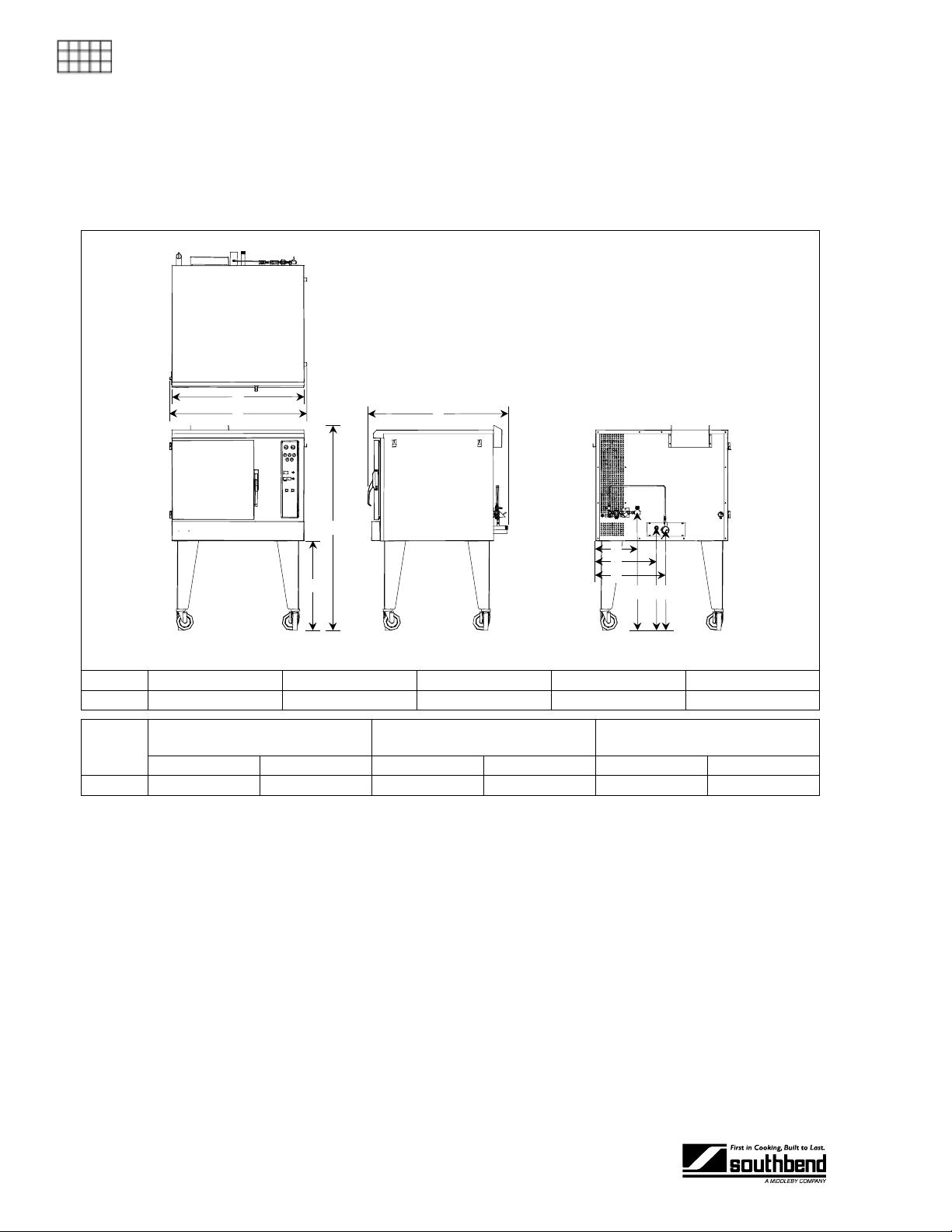
DIMENSIONS
A
B
E
D
F
G
C
Internal Dimensions: 20.75" Wide, 31.75" Deep, 22" High
Model Cabinet Width (A) Overall Width (B) Leg Height (C) Overall Hei ght (D) Overall Depth (E)
CG90-1 38" 39.6" 25.9" 59.1" 40.3"
Water Connection
Model
CG90-1 12.6" 33.9" 17.5" 29.5" 20.2" 28.9"
3/8" NPT (Female)
From Right (F) Above Floor (I) From Right (G) Above Floor (J) From Right (H) Above Floor (K)
Gas Supply Connection
3/4" NPT (Male)
H
JKI
Drain Tube
2" OD
GAS
Burners total 90,000 BTU. Supply pressure s hould be > 7 " W.C. for natural gas or > 11" W .C. for propane.
One 3/4" NPT male connector located on back, 17.5" from right side, 29.5" above floor (see above figure).
WATER
Cold water consumption is regu lated to approximately 0.5 gallons per minute. Water pressur e 30 psi (205
kPa) minimum, 60 psi. (410 kPa) maximum. To minimize service problems and to meet warranty
requirements, a water treatment system (softener) is recommended if water quality does not meet the
following specif ications: total dissolv ed solids (TDS) 60 ppm , hardness 2 grains or 3 5 ppm, pH f actor7.0 to
7.5. Install a water treatment system ( softener) if necess ary. Connector is a 3/8 " female NPT "tee" loc ated
on the back of the oven, 12.6" from right side, 33.9" above floor (see above figure).
DRAIN
Drain line is a 2" OD t ube extendi ng from the back of the ove n, 20.2" f rom right side, 28.9" abo ve floor (see
above figure). Drain outlet must be unobstructed and free-venting to atmospheric pressure! See page 11.
PAGE 4OPERATOR’S MANUAL 1180963
Page 5

COMBINATION OVEN SPECIFICATIONS
ELECTRIC
Maximum 8.0 amps (use 15 amp circuit breaker). Three voltage options:
120 VAC, 60 Hz, 1 phase: Six-foot cord with three-prong plug (standard option).
208 VAC, 60 Hz, 1 or 3 phase: Wire junction box to terminal block located near rear of motor compartment.
240 VAC, 60 Hz, 1 or 3 phase: Wire junction box to terminal block located near rear of motor compartment.
All units are shipped single-phase. Single-phase units can be easily operated on three-phase systems.
CLEARANCES
See page 8.
CONSTRUCTION (BIDDING) SPECIFICATIONS
Commercial Gas Combination Steamer/Convection Oven, Single Deck:
39.6" Wide, 59.1" High (including 25.9" legs), 40.3" Deep.
Exterior Finish: Oven front, sides, and top #3 finish stainless steel. Back aluminized steel.
Door: Single door, insulated #304 stainless steel construction (interior and exterior), positive door catch,
single action release.
Oven Interior: #304 stainless steel, including heat exchangers and baffle.
Rack & Rack Guides : Stainless s teel heav y-duty removabl e wire rack guides spaced on 1-5/8" c enters of fer
11 rack positions. Stainless steel heavy-duty removable safety-stop racks are provided with each cavity.
SPECIFICATIONS
Blower Fan & Motor : 1/2 horsepo wer, 2-spee d motor, 1725/11 40 rpm. Motor mounte d in na turally v entilated
compartment, away from heat zone. Motor serviceable from right side.
Control Panel: Located on front, at right side of oven, away from heat zone. Panel slides out for easy
servicing.
Solid State Controls allow oper ator to selec t Convection O ven, Convect ion Steam er or Com bination modes,
in addition to controlling fan speed, steam injection, and cool-down modes. Time/temperature dial
controls with digital disp lays.
DESIGN FEATURE SPECIFICATIONS
• Condensate spray with free venting exhaust
• Automatic cool down mode
• Interior washdown hose
• Rear condensate drain
NOTICE
INTENDED FOR COMMERCIAL USE ONLY. NOT FOR HOUSEHOLD USE.
OPERATOR’S MANUAL 1180963 PAGE 5
Page 6

INSTALLATION COMBINATION OVEN
INSTALLATION
Do not locate unit adjacent t o any high heat or greas e pr od uc in g p iece of eq ui pment, such as a range
top, griddle, fryer, etc., that could allow radiant heat to raise the exterior temperature of the
INSTALLATION
combination oven above 130°F (54°C). DO NOT MOUNT ABOVE OTHER COOKING EQUIPMENT.
These installation procedures must be followed by qualified personnel or warranty will be void.
Local codes regarding install ation var y greatly from one area to an other. T he National F ire Protec tion
Association, Inc. states in its NFPA 96 latest edition that local codes are the “authority having
jurisdiction” when it com es to installation r equirements for equipment. Theref ore, installations shou ld
comply with all local codes.
! CAUTION
NOTICE
The unit, when installed, must be electrically grounded and comply with local codes, or in the
absence of local codes with the Nation al Electrical Code, ANSI/NFPA 70, or the Canadian Electr ic
Code, CSA C22.2, as applicable.
Installation must comply with National Fuel Gas Code, ANSI Z223.1, Natura l Gas Installation Code,
CAN/CGA-B149.1, or the Propane Installation Code, CAN/CGA-B149.2, as applicable.
Step 1: Unpack
IMMEDIATELY INSPECT FOR SHIPPING DAMAGE
All containers shou ld be examined for dam age before and during unlo ading. The freight car rier has
assumed responsibility for its safe transit and delivery. If damaged equipment is received, either
apparent or concealed, a claim must be made with the delivering carrier.
Apparent damage or l oss m u st be noted on the freight b ill at the t im e of deliver y. T he f reight bi ll m ust
then be signed by the c arrier representative (Dr iver). If the bill is not sign ed, the carrier may ref use
the claim. The carrier can supply the necessary forms.
A request for insp ection must be m ade to the carrier within 15 da ys if there is concea led damage or
loss that is not apparent until after the equipment is uncrated. The carrier should arrange an
inspection. Be certain to hold all contents plus all packing material.
1. Uncrate carefully. Report any hidden damage to the freight carrier IMMEDIATELY.
2. Do not remove any tags or labels until unit is installed and working properly.
PAGE 6OPERATOR’S MANUAL 1180963
Page 7

COMBINATION OVEN INSTALLATION
Step 2: Install the Legs
A set of legs is pac k ed in the unit. The le gs c an be a dj us ted t o o ver come a slightly une ve n f loor. When legs
with casters have been ordered, the casters are provided with a Zerk fitting for proper lubrication when
required.
1. Raise oven sufficiently to allow legs to be bolted to the bottom corners. For safety, “shore up” and
INSTALLATION
OPERATOR’S ANUAL 1180963 PAGE 7
Page 8
INSTALLATION COMBINATION OVEN
Step 3: Check Clearances and Ventilation
There must be adequate clearance between oven(s) and construction. Clearance must also be
provided for servicing and for operation.
Minimum Clearances:
From Combustible Construction From Non-Combustible Construction
Back 7" 0”
INSTALLATION
Adequate clearance must be prov ided in the ais le and at the side and rear to allo w the do or to open
sufficiently to permit the removal of the racks and for serviceability.
No additional clearance is required for service as the ovens are servicable from the front.
Right Side 0" 0"
Left Side 0" 0"
Floor 0" 0"
! WARNING
! WARNING
Improper ventilation can result in personal injury or deat h. Ventilation which f ails to properly rem ove
flue products can cause headaches, drowsiness, nausea, or could result in death.
All units must be installed in s uch a manner that the flow of com bustion and ventilation air are not
obstructed. Provisions f or adequate air sup ply must be provided. Do not obstruct the f ront or rear of
the unit, as combustion air enters through this area. Be sure to inspect and clean the ventilation
system according to the ventilation equipment manufacturer’s instructions.
NOTICE
Proper ventilatio n is the owner's responsibilit y. Any problem due t o improper ventilation will not be
covered by the warranty.
Canopies are set over ranges, ovens, etc., for ventilation purpos es. It is r ecomm ended that a ca nopy extend
6” past the applianc e and the bottom edge be locat ed 6’6” from the f loor. Filters should be installed at an
angle of 45° or m ore from the horizontal . This positio n prevents drippi ng gr ease and faci litates collect ing the
run-off grease in a drip pan, unusually installed with a filt er . A st rong ex haus t f an ten ds to c reat e a vac u um in
the room and may interfere with burner performance or may extinguish pilot flames. Fresh air openings
approximately equal to the fan area will relieve such a vacuum.
The exhaust fan should be installed at least 2” above the vent opening at the top of the unit.
In case of unsatisfactory performance on any appliance, check the appliance with the exhaust fan in the
“OFF” position. Do th is on l y lo ng eno ugh to c heck equipment perf ormance. Then turn hoo d b ac k on and let it
run to remove any exhaust that may have accumulated during the test.
PAGE 8OPERATOR’S MANUAL 1180963
Page 9

COMBINATION OVEN INSTALLATION
Utility Connections
INSTALLATION
OPERATOR’S ANUAL 1180963 PAGE 9
Page 10
INSTALLATION COMBINATION OVEN
Step 4: Electrical Connections
A wiring diagram is located inside the control compartment on the right side of the pull-out control-panel
assembly. To access the control-pan el compartment, rem ove the screw at the top of the control pa nel and
pull the control panel out.
Units ordered with a 115VAC, 60Hz, sin gle-phase elec trical ratin g are fac tory-supplie d with t hree-wire cord
and three-prong plug, which fits any standard three-prong grounded receptacle.
Units ordered with a 208/240VAC, 60Hz, singl e- o r three-phase electric al r a ting are factory-equip pe d with a
2-pole terminal block located behind a cover plate located at the rear of the unit. To connect the supply
wires, remove the a ppropriate cover pl ate. Route t he suppl y wires a nd t he groun ding wire thro ugh th e str ain
relief fitting to the ter minal block . Insert the supply wires , one each, into the t wo poles of the terminal block
INSTALLATION
and tighten the screws. Insert the ground wire into the grounding lug and tighten the screw. Re-attach t he
cover plate.
Three phase units are wired as above, using on ly two supply wires. T he third wire is not used and must be
properly terminated.
All units are shipped wired as sp ecified b y factory order. Conversion between single- phase and three-phase
can be accomplis hed by referring to phase lo ading and line amperes chart on wiring diagram for wire size
and ampere requirements.
! WARNING
A POSITIVE GROUND CONNECTION IS ESSENTIAL. DO NOT ALLOW ANY TAMPERING OR
ADJUSTMENT OF ANY CONTROL OR WIRING. T HE UNIT IS FACTORY SET. ADJUSTING ANY
INTERNAL COMPONENT OTHER THAN THE MAIN FUSE BLOCK CAN VOID THE WARRANTY.
! WARNING
ELECTRICAL GROUNDING INSTRUCTIONS
This appliance is equipped with a three-prong (grounding) plus for your protection against shock
hazard and should b e plugg ed dir ectl y into a pr operl y ground ed thr ee-pro ng rece ptacl e. Do n ot cut or
remove the grounding prong from the plug.
Step 5: Connect Water Supply
Connect a cold water line to the 3/8" fem ale NPT "tee" connector located on the back of the oven (at the
lower left-hand side when facing the back of the oven, see figure on page 9).
To facilitate cleaning, plus allow access to the rear of the unit, flexible connections are recommended.
NOTICE: WATER SPECIFICATION
To meet warranty requirements, supply water must meet the following specification:
Pressure ...........................................30 to 60 psi (205 to 410 kPa)
Total Dissolved Solids (TDS) ...........60 PPM
Hardness ..........................................2 Grains or 35 PPM
pH Factor..........................................7.0 to 7.5
PAGE 10 OPERATOR’S MANUAL 1180963
Page 11
COMBINATION OVEN INSTALLATION
Step 6: Water Drain
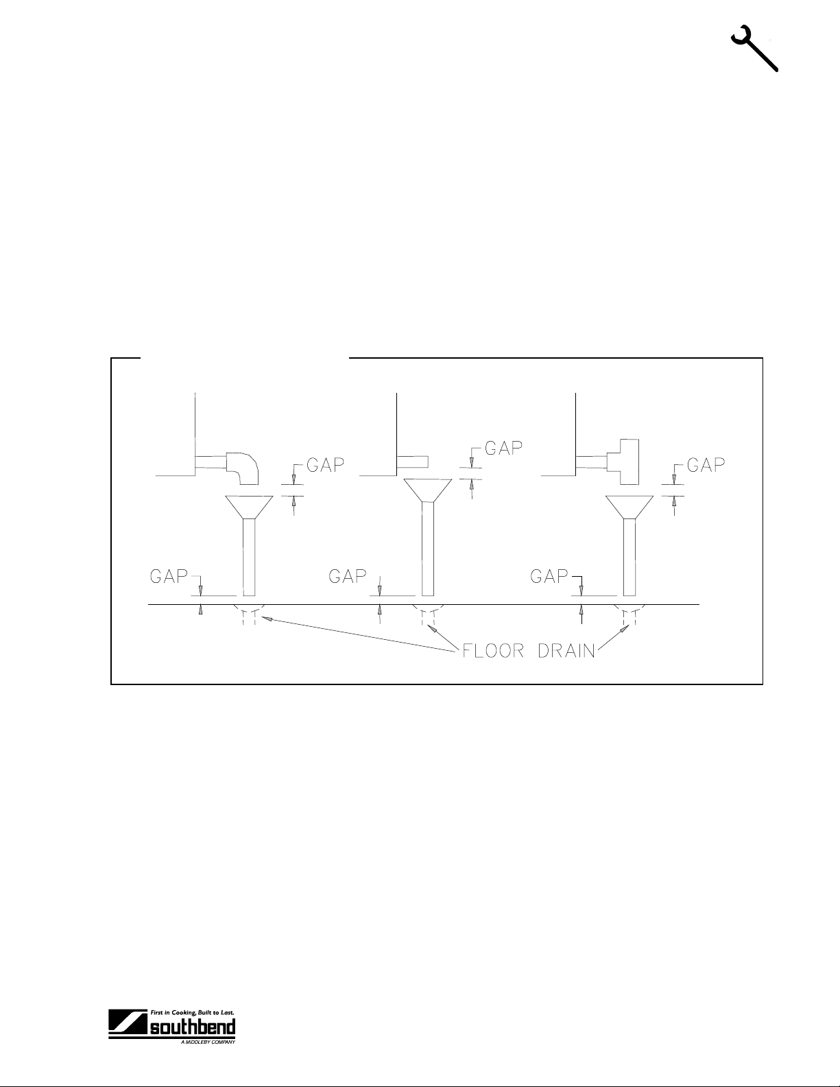
The drain line from the oven is a 2" O.D. tube (see figure on page 9) . Positi on the ove n near, but n ot on top
of, an open floor drain. DO NOT directly plumb to the oven unless you also install an “open funnel”
downstream of this connectio n in the drain s ystem. Make the drain li ne f rom the unit to the air g ap a bo ve t he
"open funnel" as shor t as possible. T here should be no h orizontal piping bet ween the oven and the air gap
over the "open funnel." T he "o pen funnel" is in ten ded to el iminate any water from entering the oven bec aus e
of a blocked drain, and it also prevents an y back pressure within the oven cavity. The o ven must be f reeventing to the atmosphere. A ny connection th at allows the b uild-up of back pressure in the o ven (such as a
reduction in pipe s i ze t o a lin e s maller than 2" or a 9 0 de gree angle in the line pr ior to t he "open funn el " dr ain
discharge point) may cause personal or property damage and therefore will void the warranty. This is a
pressureless, free- venting ove n and will not o perate proper ly unless the drain line is short, at a steep angle ,
and open!
Water Drain Open Funnel
INSTALLATION
OPERATOR’S ANUAL 1180963 PAGE 11
Page 12
INSTALLATION COMBINATION OVEN
Step 7: Gas Connection
If this equipment is being installed at over 2, 000 feet altitude an d that information was not specified when
ordered, contact the appropriate authorized Southbend Service Representative or the Southbend Service
Department. Failure to install with proper orifice sizing will result in poor performance and may void the
warranty.
The serial plate is located behind the lo wer f ront pane l on th e lef t side. It ind icates th e t ype of gas the u nit is
equipped to burn. All Southbend equipment is adjusted at the factory. Check type of gas on serial plate.
This appliance should be connected ONLY to the type of gas for which it is equipped.
A 3/4" male NPT line is provided at the rear for the connection. Each oven is equipped with an internal
pressure regulator whic h is s et f o r 4 " W.C. manifold pres s ure f or natur a l g as or 1 0.0 " W.C. manifold pres s ure
INSTALLATION
for propane gas. Use the 1/8" tap on the top of the gas valve for checking pressure.
If applicable, the ven t line from the gas appliance pressure regulator shall be installed to the outdoors in
accordance with local codes or, in the absence of local codes, with the National Fuel Gas Code, ANSI
Z223.1, Natural Gas Installation Code, CAN/CGA-B149.1, or the Propane Installation Code, CAN/CGAB149.2, as applicable.
An adequate gas supply is imperative. Undersized or low pressure lines will restrict the volume of gas
required for satisf actor y perf ormanc e. Fluctua tions of m ore than 25% on nat ural gas or 10% on pro pane gas
will create problem s and affect burner operating char acteristics. A 1/8” pressure tap is located on the gas
valve to measure the manifold pressure.
An adequate gas s upp ly li ne t o th e u nit s hou ld be n o s maller than the I.D. of the pipe from the unit to which it
is connected.
Purge the supply line to clean out dust, dirt, or other foreign matter bef ore connecting the line to the unit.
Each oven has a manual shut off valve located behind the lower front panel.
Use pipe joint compound which is suitable for use with LP gas on all threaded connections.
! CAUTION
ALL PIPE JOINTS AND CONNECTIONS MUST BE TESTED THOROUGHLY FOR GAS LEAKS.
USE ONLY SOAPY W ATER FOR TESTING O N ALL GASES. NEVER USE AN O PEN FLAME T O
CHECK FOR GAS LEAK S. ALL CONNECTIONS MUST BE CHEC KED FOR LEAKS AFTER T HE
UNIT HAS BEEN PUT INTO OPERATION. TEST PRESSURE SHOULD NOT EXCEED 14” W.C.
PAGE 12 OPERATOR’S MANUAL 1180963
Page 13

COMBINATION OVEN INSTALLATION
Step 8: Installation and Performa nce C heck
The following items should be checked by a qualified service technician:
1. Verify that oven is level.
2. Verify proper electrical characteristics (voltage, cycle, phase).
3. Check ventilation.
4. Check electrical connections (external and internal).
5. Check door(s) for proper alignment, tension, seal, and adjustment.
6. Check timers, switches and motor for proper installation and operation.
7. Check for any damage to unit from shipping or installation.
8. Check for proper clearance from combustible materials.
9. Verify proper type of gas.
10. Verify gas supply pressure (pressure regulator is already installed at factory).
11. Check gas connection and check for gas leaks.
12. Check water connection and check for water leaks.
It is common for new products to require a burn-off time to dry out insulation and metal cooking surfaces.
INSTALLATION
OPERATOR’S ANUAL 1180963 PAGE 13
Page 14

OPERATION COMBINATION OVEN
OPERATION
NOTICE
No attempt should be made to operate oven during a power failure.
A manual gas shutoff valve is located behind front lower panel for turning gas on and off.
OPERATION (FOR STANDARD CONTROL OPTION)
Lighting the Combi – The Combi has an inter m ittent st anding pilot . When the un it is turn ed o n, the light ing
sequence is control led by an ignition module. A hot surface ignitor ignites th e pilot, which stays lit for the
entire time the Combi is turned on and the flame is proven by the flame sensor.
Re-Lighting the Combi – If the Combi does not light on the first attempt, do the following:
1. Shut off all gas.
OPERATION
2. Wait five minutes.
3. Repeat lighting instructions above.
Turning the Combi On and Off – The power switch at t he top left c orner of th e control pane l turns the unit
on and off. When the power switch is tur ned on, the Com bi begins a diagnostic check and in itiates the pilot
lighting sequence. If the diag nostic c heck or the lighti ng se quence fails, a cod e wor d will appear in the t ime
display and operation wi ll be sus pend ed. Ot herwis e the un it wil l beg in opera tio n in th e startu p def ault m ode,
which is oven mode at 350ºF.
Choosing Fan Speed – The Combi has a two speed fan whic h c an b e controlled with the f an speed selector
switch at the upper right hand corner of the control panel.
Choosing the Cooking Mode
Oven Mode is selected by pressing the OVEN button, which causes t he light above the OVEN button to
illuminate. In oven mode, the Combi acts exactly like a convection oven. If when the OVEN mode
button was pressed the unit is not at the setpoint tem perature, the tem perature dis pla y will flash unt il the
setpoint temperature is reached.
Steam Mode is selected by pressing th e STEAM b utton, which ca uses the light above the ST EAM button to
illuminate. In steam mode, the Com bi ac ts ex ac tl y lik e a pr es sur eles s c ou nter to p c on vect ion s t eamer. If
when the STEAM mode button was pressed the uni t is not at the setp oint temperatur e, the temperatur e
display will flash until the s etpoint temperature is reached. In steam m ode, the setpoint temperatur e is
preset to 215ºF, to allow pure, slightly superheated steam to circulate within the cavity.
Combi Mode is selected by pressing th e COMBI button, which c auses the light abov e the COMBI button to
illuminate. In com bi mode, a high m oisture cooking envir onment is create d through caref ully controlled
humidification. If when th e COMBI m ode butto n was press ed the un it is not at t he setpo int temper ature,
the temperature display will flash until the setpoint temperature is reached.
Steam Inject Mode is the only mode that c an used in conjunc tion with another c ooking mode, nam ely oven
mode. Pressing the STEAM INJECT button ca uses s team to be delivered to t he c avi t y for as l ong as th e
button is held. The intent is to provide the des ired surface c haracteristics (crispy, shiny crus t) on bread
products, and for any other products that would benefit from timely steam injections.
Vent/Cool Mode is designed to quickly cool t he cavi ty from a high setpo int tem perature to a low tem perature
using a combination of high fan speed and a cooling spray of water
PAGE 14 OPERATOR’S MANUAL 1180963
Page 15

COMBINATION OVEN OPERATION
Setting Cooking Temperature – The cooking temperature can be s et in oven mode and Com bi mode but
not in steam mode. In steam mode, the setpoint temperature is preset to 215ºF, to allow pure, slightly
superheated steam to circulate within the cavity. The t emperature range in oven mode and Com bi ode is
145ºF to 500ºF.
Setting Cooking Time – The cooking tim e can be set by turning the tim e knob to the d esired setting and
pressing the START/INT ERRUPT button. W hen the tim er tim es out, the alarm sounds. Ho wever, the oven
continues to run in the mo de and at t he temper ature th at w ere in effect when the time expired. If the
cooking mode is changed while the tim er is counting down, the tim er simply continues to count do wn. If the
timer is timed out (00:00) when the cook ing mode is changed, then the unit runs continuously in the new
mode. To disable the beeper after the timer has expired, press the START/INTERRUPT button ag ain. The
CANCEL button will reset the time to zero.
OPERATION
OPERATOR’S ANUAL 1180963 PAGE 15
Page 16

OPERATION COMBINATION OVEN
Operation of Combination Oven with Standard Controls
OPERATION
PAGE 16 OPERATOR’S MANUAL 1180963
Page 17

COMBINATION OVEN COOKING HINTS
COOKING HINTS
All times and tem peratures are estimates and s hould be verified in actua l practice. Starting tem perature of
food, pan size/fullness, and opening oven during cooking will affect cooking times.
Baked Goods
Menu Item Mode Temperature Cooking Time Proper Pan Tips
Apple pie, mile-high Oven 350°F/175°C 50 min. Pie tins on
wire racks
Biscuits Oven 325°F/165°C 15 min. Sheet pan Can also use Combi mode at
350°F/175°C
Biscuits, cinnamon raisin Oven 325°F/165°C 15 min. Sheet pan Also try in Combi mode
Bread sticks (soft style, raw
dough)
Cake layers Oven 300°F/150°C 25 min. Sheet pans
Carrot cake layers Oven 325°F/165°C 25 min. Sheet pans
Cheesecake Combi 325°F/165°C 1 hour
Cherry crisp Combi 325°F/165°C 30 min. 2 ½” pan,
Chocolate brownies Oven 325°F/165°C 25 min. Sheet pans
Coffee cake, apple Oven 300°F/150°C 25 min.
Coffee cake, sour cream Oven 300°F/150°C 25 min. Also try in Combi mode
Cookies, butter sugar Combi 300°F/150°C 10 min. Sheet pan Also try in oven mode
Cookies, oatmeal raisin Oven 325°F/165°C 15 min. Sheet pan
Cookies, peanut butter
chocolate chunk
French bread Combi 375°F/190°C 20 min. Sheet pan See hard roll procedure
Hot seasoned apples Combi 250°F/120°C 15 min. 2 ½” pan,
Combi 325°F/165°C 10 min. Sheet pan 375°F/190°C for crispier sticks
uncovered
Oven 300°F/150°C 12 min. Sheet pan Higher temperature for crispier
cookies
uncovered
COOKING HINTS
Muffins (blueberry, banana nut) Oven 350°F/175°C 20 min. Muffin pans Preheat to 400°F/205°C, load
oven,, turn off for 6-8 min., then
bake at indicated temperature
Rolls, dinner Combi 325°F/165°C 20 min.
Rolls, hard Combi 375°F/190°C
250°F/120°C
350°F/175°C
Rolls, sweet Combi 325°F/165°C 20 min. Sheet pan Also try in oven mode
Rolls, whole wheat Combi 325°F/165°C 25 min. Sheet pan
OPERATOR’S MANUAL 1180963 PAGE 17
Preheat
5 min.
15 min.
Sheet pan Low temp stage produces better
crust – can be eliminated – keep
total time
Page 18

COOKING HINTS COMBINATION OVEN
Beef and Veal
Menu Item Mode Temperature Cooking Time Proper Pan Tips
BBQ beef (raw brisket) Combi 250°F/120°C
375°F/190°C
Beef Sausage links Steam 350°F/175°C 10 min. May also be steamed
Braised beef w/mushrooms Combi 250°F/120°C 1 hour 2 ½” pan,
Corned beef hash Combi 250°F/120°C 25 min. 2 ½” solid pan
Fillet steak Combi 500°F/260°C 10 min. Oiled sheet
Grilled flank steak Combi 500°F/260°C 10 min. Wire rack Oil steak
Hamburger pie Combi 325°F/165°C 30 min. 2 ½” pan,
Hamburgers (Frozen patties) Combi 400°F/205°C 10 min. Perforated
Herbed pot roast Combi 250°F/120°C 3 hours 2 ½” solid pan
Hot dogs Steam N/A 7 min. 2 ½”
London broil Combi 500°F/260°C 15 min. Preheated
COOKING HINTS
90 min. + 10
min at higher
temp.
Cook with sauce at low heat,
raise temp. to set glaze
uncovered
pan
uncovered
sheet pan
perforated
Oil steaks
racks
Marinated sirloin steak Combi 500°F/260°C 10 min. Oiled sheet
pan
Meatloaf Combi 300°F/150°C 40 min. 2 ½” pan,
uncovered
New York strip Combi 500°F/260°C 8 min. Wire racks Oil steaks
Prime Rib Combi 275°F/135°C 2 ½ hours Wire rack Bone in - Export 10-12lbs
Ribeye sandwich steak Combi 500°F/260°C 5 min. Wire rack and
catch pan on
bottom
Roast beef Combi 275°F/135°C 2 ½ hours Sheet pan or
wire rack
Roast beef hash (re-therm) Combi 250°F/120°C 25 min. 2 ½” solid pan
Rump steak Combi
Salisbury steak w/gravy
(re-therm)
Teriyaki steak Combi 400°F/205°C 10 min. Sheet pan
Combi 250°F/120°C 20 min. 2 ½” solid pan
Brush w/melted butter, preheat
oven well
PAGE 18 OPERATOR’S MANUAL 1180963
Page 19

COMBINATION OVEN COOKING HINTS
Fish and Shellfish
Menu Item Mode Temperature Cooking Time Proper Pan Tips
Crab Steam N/A 8-10 min. 2 ½”
perforated pan
Halibut Combi 325°F/165°C 6 -7 min. ½ size sheet
pan
Perch Oven 400°F/205°C 5 min. Sheet pan Brush pan w/oil and season fish
Salmon (fresh) Combi 325°F/165°C 8-10 min. 2 ½”
perforated
Shrimps – frozen Steam N/A 3-5 min. 2 ½”
perforated pan
Trout Oven 400°F/205°C 5 min. Sheet pan Brush pan w/oil and season fish
20-25 ct.
Pork and Lamb
Menu Item Mode Temperature Cooking Time Proper Pan Tips
Bacon slices Combi 325°F/165°C 15 min. Sheet pan Single layer
Baked ham Combi 300°F/150°C 1 hour Sheet pan
Baked pork chops Combi 325°F/165°C 20 min. Sheet pan Single layer
BBQ boneless rib for sandwich
(retherm)
BBQ pork for sandwich (Boston
butts, raw)
Bratwurst Steam N/A 10 min. 2 ½”,
Canadian bacon Combi 400°F/205°C 5 min. Sheet pan Single layer
Grilled butterflied pork chops Combi 400°F/205°C 10 min Sheet pan Oil chops
Grilled ham slice Combi 400°F/205°C 10 min. Wire rack Preheat to 450F
Combi 250°F/120°C 15 min. Sheet pan
Combi 250°F/120°C 2 hours Sheet pan,
with sauce
uncovered
COOKING HINTS
Grilled pork cutlet Combi 400°F/205°C 15 min. Sheet pan Single layer
Grilled pork tenderloin Combi 400°F/205°C 15 min. Oiled, wire
rack
Italian sausage Combi 375°F/190°C 15 min. Sheet pan
Kielbasa Combi 375°F/190°C 15 min. Sheet pan Single layer
Knockwurst Steam N/A 15 min. 2 ½”
perforated pan
Pork sausage link Combi 350°F/175°C 15 min. Sheet pan Single layer
Roast pork Combi 300°F/150°C 50 min. Sheet pan or
wire rack
Sausage patties Combi 300°F/150°C 15 min. Sheet pan Steam for better yield
OPERATOR’S MANUAL 1180963 PAGE 19
150F internal, rest 20 minutes
Page 20

COOKING HINTS COMBINATION OVEN
Potatoes, Pasta, and Grains
Menu Item Mode Temperature Cooking Time Proper Pan Tips
Baked potatoes Oven 375°F/190°C 40 min. Sheet pan
Poultry
Vegetables
COOKING HINTS
New, red potatoes Steam N/A 17 min. 2 ½”
perforated
Rice (short grain) Steam N/A 20 min. 2 ½” pan,
covered
Menu Item Mode Temperature Cooking Time Proper Pan Tips
Chicken wings Combi 375°F/190°C 15 min. Sheet pan
Chicken, half Combi 325°F/165°C 25 min. Sheet pan
Chicken, whole Combi 325°F/165°C 35 min. Sheet pan
Turkey Combi 375°F/190°C 2 hrs, 15 min. Sheet pan
Turkey breast Combi 325°F/165°C 1 hour Sheet pan
Menu Item Mode Temperature Cooking Time Proper Pan Tips
Asparagus Steam N/A 8 min. 2 ½”
perforated
Asparagus & egg au gratin Steam N/A 14 min. 2 ½” solid
Cut in quarters
2 parts rice, 1 part stock
Beans (frozen, whole or cut) Steam N/A 12 min. 2 ½”
perforated
Broccoli (fresh spears) Steam N/A 8 min. perforated
Broccoli cheese casserole Combi 300°F/150°C 30 min. 2 ½” solid
Cabbage Steam N/A 15 min. 2 ½”
perforated
Cabbage, red (frozen) Steam N/A 18 min. 2 ½”
perforated
Carrots, fingerling Steam N/A 10 min. 2 ½”
perforated
Carrots, glazed (frozen
w/ sauce)
Carrots, sliced (raw) Steam N/A 12min. 2 ½”
Cauliflower (fresh florets) Steam N/A 8 min. 2 ½”
Corn (frozen niblets) Steam N/A 8 min. 2 ½”
Corn on the cob Steam N/A 12 min. 2 ½”
Steam N/A 10 min. 2 ½” pan,
uncovered
perforated
perforated
perforated
perforated
Blanch fresh, cold water
Remove stalk
PAGE 20 OPERATOR’S MANUAL 1180963
Page 21

COMBINATION OVEN COOKING HINTS
Vegetables, continued
Menu Item Mode Temperature Cooking Time Proper Pan Tips
Green beans w/water chestnuts Steam N/A 10 min. 2 ½”
perforated
Green beans, French cut
(frozen)
Green beans, whole Steam N/A 10 min. 2 ½”
Italian vegetables (frozen) Steam N/A 13 min. 2 ½”
Mixed vegetables (frozen) Steam N/A 10 min. 2 ½”
Mushrooms Steam N/A 8 min. 2 ½” solid pan Sprinkle w/lemon, white wine
Peas and mushroom (frozen) Steam N/A 14 min. 2 ½”
Peas, garden (frozen) Steam N/A 7 min. 2 ½”
Ratatouille Combi 300°F/150°C 20 min. 2 ½” solid pan Toss with oil before cooking
Snap peas, sugar (frozen,
seasoned)
Spinach (fresh) Steam N/A 7 min. 2 ½”
Spinach (frozen) Steam N/A 14 min. 2 ½”
Steam N/A 10 min. 2 ½”
perforated
perforated
perforated
perforated pan
perforated
perforated
Steam N/A 10 min. 2 ½” pan,
uncovered
perforated pan
perforated
Separate ice-encased
vegetables
Separate ice-encased
vegetables
COOKING HINTS
Squash (fresh) Steam N/A 7 min. 2 ½”
perforated
Vegetable primavera casserole Combi 275°F/135°C 30 min. 2 ½” solid pan
Vegetarian stir-fry Combi 375°F/190°C 10 min. 2 ½”
perforated
Zucchini (fresh) Steam N/A 7 min. 2 ½”
perforated
Zucchini w/ basil Steam N/A 7 min. 2 ½”
perforated
Toss w/oil, add sauce after
cooking
OPERATOR’S MANUAL 1180963 PAGE 21
Page 22

CLEANING COMBINATION OVEN
CLEANING
Southbend equipment is constructed with the best quality materials and is designed to provide durable
service when properl y maintained. To expect the b est performance, your equipment must be m aintained in
good condition and cleaned dail y. Naturally, the frequenc y and extent of cleaning depends on the amount
and degree of usage.
Following daily and more extensi ve peri odic maintenance proced ur es will increase the l if e of your equipment.
Climatic conditions (i.e., salt air, seasonings, and water quality) may result in the need for more thorough and
more frequent cleaning in order to keep equipment performing at optimal levels.
! WARNING: BURN HAZARD
For proper and safe operation, this oven must be cleaned daily as described in this manual. Failure
to do so could result in serious injury or damage.
Drains must be kept clean and clear of debris.
! WARNING: SHOCK HAZARD
DO NOT GET WATER IN THE CONTROLS.
This could result in expensive repairs and/or electrical shock.
CLEANING
VENT SYSTEM: At least twice a year, the unit's venting system should be examined and cleaned.
MOTOR: Lubrication information can be found on the permanent label located on motor.
DAILY CLEANING
• Use pump-up spr ayer (So uthbend P art# 1180973) supp lied with the unit to spra y RCS Specia l Clea ning
Agent (Southbend Par t# 1180974) ins ide the oven cav ity, behind the air baffle, and on t he inner side of
the door. (CAUTION : Do not spray RCS Special Cleaning A gent into a hot oven! Discolorat ion of the
interior surfaces wil l result. The oven tem perature must be be low 130ºF (55ºC) bef ore spraying cleaner
into the cabinet.)
• Turn the oven on and place the oven in STEAM mode for 15 minutes.
• If the unit is heavily soiled, repeat the above steps.
• Thoroughly rinse th e inside of the oven ca vity with the spra y nozzle and spra y hose assembly sup plied
with the unit.
De-energize all power to equipment before cleaning the equipment.
NOTICE
• Make sure drain opening is clear.
• Leave the door open at night after clean in g.
• Do not clean the door gasket with a high-chlorine solution or bleach.
• Do not use steel wool or other metallic pads in the oven.
PAGE 22 OPERATOR’S MANUAL 1180963
Page 23

COMBINATION OVEN CLEANING
PERIODIC CLEANING
• If lime or mineral deposit star ts to build up in the i nterior , clean t he u nit b y using Southb end “ descal er” or
other non-caustic de liming solution. Fol low manufacturer’s r ecommended procedures. T horoughly rinse
out unit with clean water.
• To remove normal dirt, grease, or product residue from stainless steel, use ordinary soap and water
applied with a sponge or cloth. Dr y thoroughly with a clean cloth. Nev er use vinegar o r any corrosiv e
cleaner.
• To remove grease and food splatter or condensed vapors that have baked on the equipment, apply
cleanser to a dam p cloth or sponge and r ub cleanser on the metal in th e direction of the po lishing lines
on the metal. Rubbing cleanser as gent l y as possi ble in the direction of the polished lin es will not mar the
finish of the stainles s steel. NEVER RUB WITH A CIRCU LAR MOTION. So il and burnt dep osits which
do not respond to the above procedure c an usually be remove d by rubbing the surf ace with SCOTCHBRITE scouring pads . DO NOT USE ORDINAR Y ST EEL WOOL, as any par tic les lef t on t he s urf ace will
rust and further spoi l the appearance of the finish. NEVE R USE A WIRE RUSH, STE EL SCOURING
PAD, SCRAPER, FILE OR OTHER ST EEL TOOLS. Surf aces which are marr ed collect dirt m ore rapidl y
and become more difficult to clean. Marring also increases the pos sibilit y of corros ive attack . Refinish ing
may then be required.
SEMIANNUAL CLEANING
At least twice a year, have your Southbend Authorized Service Agency or another qualified service
technician clean and adjust the unit for maximum performance.
Consult the Southbend Authorized P arts/Servic e Distributor list for th e Authorized Service Representat ive in
your area or contact Southbend at 1-800-348-2558 for this information.
CLEANING
OPERATOR’S MANUAL 1180963 PAGE 23
Page 24

TROUBLESHOOTING COMBINATION OVEN
TROUBLESHOOTING
NOTICE
Service work should be performed only by a qualified technician who is experienced in, and
knowledgeable of, the operation of commercial gas cooking equipment. Contact the authorized
Southbend Service Agency for reliable service, dependable advice or other assistance, and for
genuine factory parts.
Warranty will be void and the manufacturer is relieved of all liability if:
(A) Service work is performed by other than a qualified technician,
OR
(B) Other than genuine Southbend replacement parts are installed.
! CAUTION
Whenever servicing or cleaning the oven, the main power supplies to the oven must be disconnected.
This section cont ains a tr oubl eshootin g k ey and r eferenc ed f lowchar ts to as sist a qua lifie d serv ice tech nic ian
in the servicing of a Southbe nd Com bi oven. T he South bend Com bi is e quipped with a print ed circ uit b oard
controller that undergoes a diagnostic check every time the Combi is turned on. This diagnostic check
requires between 35 and 105 seconds. During this time, every segment in the display LEDs will be
illuminated. In the event of a diagnostic error, “Err” will appear in the TEMPERATURE display and a
descriptive error code will app ear in the TIME display. To recover from error mode, the problem must be
fixed and the unit turned off and back on again. A table of error codes and their causes is listed below:
Error Code Cause
CP:U The controller has failed a check of its on-board RAM (controller will need replaced)
bu:tn A button on the control panel is sticking in the down position or a button was held by the operator during startup
FA:n The cavity temperature limit switch or the centrifugal switch incorporated into the motor has tripped, indicating a
possible failure of the blower motor
GA:S A gas error can be caused by a variety of problems and is listed separately as a symptom in the following
troubleshooting guide (see page 28)
Pr:0b At least one of the RTD probes has failed in either an open or shorted condition.
TROUBLESHOOTING
PAGE 24 OPERATOR’S MANUAL 1180963
Page 25

COMBINATION OVEN TROUBLESHOOTING
TROUBLESHOOTING KEY
Find the symptom below that corresponds to th e malfunction, then tur n to t he c or res p ond ing f igure and page.
Follow the flowchart on that page until the problem is solved.
Symptom Page
Unit Not Working, No Lights 26
Unit Not Heating Properly (No Gas Error) 27
Gas Error 28
Unit Not Steaming Properly in Steam Mode or Combi Mode 29
Blower Not Running Properly 30
TROUBLESHOOTING FIGURES AND PROCEDURES
Figure and/or Procedure Page
Electric Schematic for 120 Volt 60 Hz Models 31
OPERATOR’S MANUAL 1180963 PAGE 25
TROUBLESHOOTING
Page 26

TROUBLESHOOTING COMBINATION OVEN
Unit Not Working, No Lights
Unit Not Working, No Lights.
Check circuit breaker
Ensure 120V between terminals TBA1
and TBA2 of terminal block A.
Check voltage between where Wire 57
attaches to fuseblock and TB-B2.
Is voltage
No Yes
approximately
120 volts?
Test and
replace fuse,
as necessary.
between TB-B1 and TB-B2.
No Yes
Test and
replace power
switch, as
necessary.
With switch in "ON"
position, check voltage
Is voltage
approximately
120 volts?
Check voltage between
terminals TB-B3 and TB-B6.
No Yes
Test and replace
transformer, as
necessary.
Is voltage
approximately 24
volts?
Check wiring.
Replace
control board.
TROUBLESHOOTING
PAGE 26 OPERATOR’S MANUAL 1180963
Page 27

COMBINATION OVEN TROUBLESHOOTING
Unit Not Heating Properly (No Gas Error)
Unit Not Heating Properly (No Gas Error)
Disconnect power. Remove control panel thumbscrew and
slide control panel out, Reconnect power.
Start unit. Check gas supply pressure. (There is an inlet
pressure tap on the gas combination valve that can be used
for this purpose.) Supply pressure should be > 7" W.C. for
natural gas and > 11" W.C. for propane.
Remove front lower panel and burner box cover.
With door
No
Place unit in oven
mode at 500
°F.
Close door.
closed, do main
burners come
on?
Yes
Place unit in oven
mode at 200°F.
Open door.
Depress door switch.
Check voltage between
HI terminal and C
terminal of gas valve.
No Yes
approximately 24
Replace control board.
Is voltage
volts?
Replace gas valve.
No
Go to page 29,
Blower Not
Running Properly.
No Yes
Replace gas
combination valve.
Does
blower come
on?
Check gas manifold pressure.
(There is a tap on the gas
combination valve for this
purpose.) Pressure should be
approximately 4.0" W.C. for
natural gas or approximately
10.0" W.C. for propane.
Does gas
pressure meet
specifications?
Yes
TROUBLESHOOTING
Check gas
valve wiring.
OPERATOR’S MANUAL 1180963 PAGE 27
Page 28

TROUBLESHOOTING COMBINATION OVEN
Gas Error
Gas Error
Ensure that gas shut-off valve is open.
Check gas supply pressure. (There is an inlet pressure tap on the gas combination valve that can be
used for this purpose.) Supply pressure should be > 7" W.C. for natural gas or > 11" W.C. for propane.
Remove front lower panel and burner box cover. Turn unit on. Observe ignitors for first 101 seconds after
turning unit on. Ignitors should begin glowing and continue to glow for approximately 37 seconds.
(If the flame does not light on first attempt, this process will be repeated two additional times.)
Do
Does
one ignitor
glow?
No
YesNo
both ignitors
glow?
Yes
No
Do both pilot
flames light (at least
temporarily)?
Yes
Place test leads
between terminal
TB-C2 and TB-C1.
Turn unit on. Check
voltage during first
30 seconds of
operation.
Is voltage
No Yes
Replace RAM
module.
Check manifold pressure during first 30
seconds of operation. (There is a tap on
gas combination valve for this purpose.)
approximately 24
volts?
Test and replace
bad ignitor, as
required.
Replace both
ignitors.
Check voltage
between P and C
terminals on gas
valve during first 30
seconds of operation.
Is voltage
Yes
approximately 24
volts?
Check and replace
RAM module, as
necessary.
Make sure that flame
sensors are
positioned at tip of
inner core of pilot
flame and are not
touching any metal
surface. Retry.
No
Does main
burner come
on (with door
closed)?
Check and replace RAM
module and flame sensor,
as necessary.
YesNo
Done
No
TROUBLESHOOTING
Replace gas valve.
PAGE 28 OPERATOR’S MANUAL 1180963
Is manifold pressure approximately
4" W.C. for natural gas or approximately
10" W.C. for propane?
Remove burner box. Remove pilot supply tube from pilot(s) not lighting.
Examine and replace pilot orifice if necessary. Replace pilot if damaged.
Ensure that ignitor is positioned properly relative to pilot. Adjust as necessary.
Yes
Page 29

COMBINATION OVEN TROUBLESHOOTING
Unit Not Steaming Properly in Steam Mode or Combi Mode
Unit Not Steaming Properly in Steam Mode or Combi Mode.
Check water pressure at unit with unit running.
Disconnect plug PL3 and place test leads in harness side of
plug. Operate unit in steam mode. Wait until steam mode
LED stops flashing. Check voltage.
Does voltage
No Yes
rise and fall from 0 to
approximately
24 volts?
Check wiring.
Replace board.
No Yes
Replace
solenoid valve.
Remove screen from
strainer on back of unit.
Clean or replace screen.
Turn unit on in steam
mode.
Turn unit off. Remove
right side exterior cover
from unit, if desired.
Check solenoid valve
coil resistance.
Is resistance
between 1 and 10
megaohms?
Turn-off water supply to unit. Remove
water-supply copper tube from
compression fitting at inlet to solenoid
valve inside unit. Attach one end of 1/4"
ID hose to tube and place other end in
drain or bucket. Turn water supply on.
No Yes
Significant
water flow
(>1/2 gpm)?
TROUBLESHOOTING
Remove solenoid valve and
flow regulator. Examine for
deposits or debris that would
impede water flow. Clean and
replace as necessary.
No Yes
Replace pressure
regulator on back of unit.
Unit steaming
properly?
Finished
OPERATOR’S MANUAL 1180963 PAGE 29
Page 30

TROUBLESHOOTING COMBINATION OVEN
Blower Not Running Properly
Blower Not Running Properly (with Door Closed)
No
Does
blower run when unit is
cold (door closed)?
Yes
Disconnect 4-pin connector. Place fan switch in
"HIGH FAN" position. Locate the terminals
where Wires 21 and 55 are attached and check
for continuity between these terminals. Place
the fan switch in "LOW FAN" position. Locate
the terminals where Wires 22 and 56 are
attached. Check for continuity.
Is there
No Yes
Replace
fan switch.
continuity in both
cases?
No Yes
Reconnect 4-pin connector.
Slide control panel out. Disconnect plug PL2.
Place test leads in terminals on switch side of plug.
Close door. Check for continuity.
Open door. Check for continuity.
Is there continuity with door closed
and no continuity with door open?
Blower motor is overheating. Check operation
of cooling fan in control compartment and
replace as necessary.
Check door switch actuator mechanism by
closing door and observing movement of door
switch lever. Adjust or repair as necessary.
Replace door switch as necessary.
Put fan switch in "LOW FAN" position.
TURN OFF GAS SHUT OFF VALVE.
Close door.
motor. Turn unit on. Check voltage between
Wires 25 and 8 by inserting test leads into the
harness side of plug PL8.
No Yes
TROUBLESHOOTING
Replace control
board.
PAGE 30 OPERATOR’S MANUAL 1180963
Disconnect 3-pin connector at
Is voltage
approximately
120 VAC?
Replace motor.
Page 31

COMBINATION OVEN TROUBLESHOOTING
Figure 4
Electric Schematic for 120 Volt 60 Hz Models
OPERATOR’S MANUAL 1180963 PAGE 31
TROUBLESHOOTING
Page 32

PARTS COMBINATION OVEN
PARTS
NOTICE
INSTALLATION OF OTHER THAN GENUINE SOUTHBEND PARTS WILL VOID T HE WARRANTY
ON THIS EQUIPMENT.
The serial plate with voltage, m odel, and seria l inform ation is l ocated b ehind the lower f ront panel on the lef t
side.
Replacement parts may be ordered either thr ough a Southbend Auth orized Parts Dis tributor or a S outhbend
Authorized Service Agency.
When ordering parts, please suppl y the Model Number, Serial Number, Part Num ber, Description, Finish,
and Electrical Character istic s as appl icab le.
For parts not listed, consult a Southbend Authorized Parts Distributor or Southbend Authorized Service
Agency. Consult the Southbend Authori zed Parts/Servic e Distributor list f or the Authorized P arts supplier in
your area. If this list is not available, call Southbend at 1-800-348-2558 to obtain this list.
Index of Combination Oven Parts Diagrams
Page Number Description Module or S/A #
33 Blower and Motor Parts 0-11-0045
34 Control Panel Subassembly Parts 0-11-0046
36 Frame and Exterior Parts 0-11-0047
38 Cavity Parts 0-11-0048
40 Door Subassembly Parts 0-11-0049
41 Sprayer and Water Train Parts 0-11-0050
42 Burner and Gas Train Parts 0-11-0051
44 Water Inlet Subassembly Parts 1180668 (S/A)
45 Black Legs with Casters Parts 0-40-0498
PARTS
PAGE 32 OPERATOR’S MANUAL 1180963
Page 33

COMBINATION OVEN PARTS
Blower and Motor Parts 0-11-0045
Key Part Number Qty Description
1 1180934 1 Blower Wheel Weld Assembly
2 1180932 1 Packing Material, FDA Approved
3 1180910 1 Washer, Flat
4 1180909 1 Washer, Wave Spring, SS
5 1180903 1 Fitting, Motor Shaft Seal
6 1180686 1 Motor Pocket S/W/A
7 1180633 1 Fan, Water Dispersing
8 1180621 1 Motor, 115V 60CC 2 Speed
9 1179710 4 Spacer, Blower, Motor
PARTS
OPERATOR’S MANUAL 1180963 PAGE 33
Page 34

PARTS COMBINATION OVEN
Control Panel Subassembly Parts 0-11-0046
See drawing on following page.
Key Part Number Qty Description
1 1172275 2 Plastic Knob
2 1177515 1 Bracket, Ignition Module
3 1178391 1 Fuseblock, Controls
4 1178534 1 Bracket, On/Off Switch
5 1180617 1 Control Panel, Subassembly (assembled)
6 1180635 1 Ignition Module
7 1180636 1 Control Board
8 1180906 1 Fuse, Time-Delay, 20 A
9 1180931 1 Panel Weld Assembly, Control
10 1180971 1 Transformer 115V, 24V, 75VA
11 1180987 2 Switch, Rotary, Actuator
12 1180988 1 Switch, Rotary, NO/NC
13 1180989 1 Switch, Rotary, NO
14 1180990 2 Bezel, Rotary Switch, Black
* 1170336 1 Marker Strip
* 1180610 1 Polypanel
* 1180637 1 Wiring Harness
* 1180638 1 Electrical Schematic
* 1180970 1 Sticker, Fuse Replacement
* 1180972 8 Spacer, Control Panel (Combi)
* not shown on drawing.
PARTS
PAGE 34 OPERATOR’S MANUAL 1180963
Page 35

COMBINATION OVEN PARTS
Control Panel Subassembly Parts
See parts list on previous page.
6 POSITION TERMINAL STRIP
(PART OF WIRING HARNESS, 1880637)
2 POSITION TERMINAL STRIP
(PART OF WIRING HA RNE S S, 1880637)
OPERATOR’S MANUAL 1180963 PAGE 35
PARTS
Page 36

PARTS COMBINATION OVEN
Frame and Exterior Parts 0-11-0047
See drawing on following page.
Key Part Number Qty Description
1 1180641A 1 Trough, Drain
2 1180974 1 Switch, CO High Limit
3 1180953 2 Hanger, Hose
4 1180936 1 Frame, Vertical, Weld Assembly
5 1180935 2 Frame, Horizontal, Cavity, Weld Assembly
6 1180660 2 Bracket, Front and Rear Pipe Support
7 1180655 1 Base Weld Assembly
8 1180649 1 Retainer, Insulation
9 1180642 1 Cover, Drain Trough
10 1180631 2 Rail, Slide
11 1180625 2 Frame, Horizontal, Left/Right
12 1180624 2 Frame, Horizontal, Front/Back
13 1180623 3 Frame, Vertical
14 1180615 1 Flue Riser
15 1180613 1 Cover, Gas and Drain
16 1180612 1 Front Lower Panel
17 1180609 1 Body Back
18 1180607 1 Body Top
19 1180606 1 Body Front
20 1180605 1 Body Side, Left
21 1180604 1 Body Side, Right
22 1179709 1 Plug, Fan Power Cord
23 1179704 1 Fan, Cooling, 120V
24 1177523 1 Bracket, Rear Gas Pipe
25 1172769 1 CO Power Cord
26 1172285 1 Bushing, Strain Relief
27 1160031 1 Lug, Grounding
PARTS
PAGE 36 OPERATOR’S MANUAL 1180963
Page 37

COMBINATION OVEN PARTS
OPERATOR’S MANUAL 1180963 PAGE 37
PARTS
Page 38

PARTS COMBINATION OVEN
Cavity Parts 0-11-0048
See drawing on following page.
Key Part Number Qty Description
1 P6016 1 Fitting, Brass, STRT, 68C-6-4
2 1180998 2 Baffle, Weld Assembly
3 1180997 1 Disk, Pressure Relief
4 1180996 1 Spring, Relief Valve
5 1180992 1 Insul. Cover for Flue
6 1180983 1 Probe Bracket
7 1180982 1 Probe Bracket Clamp
8 1180962 1 Door Switch Assembly
9 1180961 1 Cover, Probe
10 1180921 8 Bolt, Shoulder 1/4-20
11 1180911 2 Rack Guide, 11 Position
12 1180682 2 Fitting, 1/4 inch MPT x 3/16 inch Tube
13 1180671 1 Flue Duct Weld Assembly
14 1180670 1 Tube, Water Supply
15 1180656 1 Baffle, Air
16 1180639 5 Racks
17 1180616 1 Cavity Weld Assembly
18 1172753 2 Thermostat Probe
PARTS
PAGE 38 OPERATOR’S MANUAL 1180963
Page 39

COMBINATION OVEN PARTS
Cavity Parts
See parts list on previous page.
OPERATOR’S MANUAL 1180963 PAGE 39
PARTS
Page 40

PARTS COMBINATION OVEN
Door Subassembly Parts 0-11-0049
Key Part Number Qty Description
1 1180977 2 Hinge, Door
2 1180940 1 Panel, Door, Weld Assembly
3 1180938 1 Door Latch & Striker
4 1180691 1 Insulation, Door
5 1180685 1 Panel Assembly, Inner Door
6 1180627 1 Gasket, Door
7 1180618 1 Door Subassembly (assembled)
8 1180614 1 Door Gasket Retainer
9 1146363 3 Screw, 1/4 -20x2, SS, Slotted Flat Head
10 1146303 8 Screw, #8 x 1/2
PARTS
PAGE 40 OPERATOR’S MANUAL 1180963
Page 41

COMBINATION OVEN PARTS
Sprayer and Water Train Parts 0-11-0050
OPERATOR’S MANUAL 1180963 PAGE 41
PARTS
Page 42

PARTS COMBINATION OVEN
Burner and Gas Train Parts 0-11-0051
See drawing on following page.
Key Part Number Qty Description
1 1036600 4 Orifice Fitting
2 1036603 8 Screw, Brass, 5/16-18x3/4 Hexhead
3 1036604 4 Nut Air Collar
4 1036605 4 Air Collar PLTD
5 1036607 4 Burner, Fry Pot, 4 inch
6 1036611 4 Burner Orifice - Nat #44 Drill
1036610 1 Orifice Spud Propane #54 Drill (option)
7 1054118 2 Pilot Orifice - Nat
1054111 1 Orifice, R-011, Propane (option)
8 1061298 1 Union, Brass
9 1099114 1 Nut, Male
10 1146304 6 Screw, #10 x 1/2 Phil Truss Head
11 1146398 4 Screw, 6-32x3/8, SS, Phil Pan Head
12 1146405 4 Nut, 6-32, Hex
13 1146501 4 Lockwasher, 3/16
14 1146526 2 Washer, #10, Flat
15 1146529 8 Washer, 5/16, Lock, SS
16 1146806 1 Nipple, Pipe, Close, Blk, 1/2"
17 1146913 1 Elbow, Red., Blk, 3/4 x 3/8, 90 Deg
18 1147007 1 Plug, Pipe Blk. 1/8
19 1160008 3 Elbow, Brass
20 1173524 1 Tee, 1/4 Tube Compr All Direct
21 1173595 2 Insert, Knurled, Threaded
22 1175283 2 Flame Sensor
23 1177545 2 Ignitor, Hot Surface
24 1180634 1 Gas Valve, Nat
1180955 1 Gas Valve, Propane (option)
25 1180659 1 Tube, Gas Supply
26 1180667 1 Cover, Burner Box
27 1180675 1 Burner Box
28 1180676 1 Manifold
29 1180678 2 Tube, Pilot Supply
30 1180679 1 Tube, Main Pilot, Up
31 1180681 1 Tube, Burner Supply
32 1180692 1 Tube, CV Outlet
33 1180693 1 Tube, Main Pilot, Down
34 1180694 2 Bracket, Pilot Mounting
35 1180945 1 Tail Pipe
36 1180960 2 Pilot
37 1180964 1 Union, Brass, 5/8 CC
38 1-5771 1 Valve, Shut Off, 1/2"
39 P9158 1 Connector, Brass, 68C-10-8
PARTS
PAGE 42 OPERATOR’S MANUAL 1180963
Page 43

COMBINATION OVEN PARTS
OPERATOR’S MANUAL 1180963 PAGE 43
PARTS
Page 44

PARTS COMBINATION OVEN
PARTS
PAGE 44 OPERATOR’S MANUAL 1180963
Page 45

COMBINATION OVEN PARTS
Black Legs with Casters Parts 0-40-0498
Key Part Number Qty Description
1 1174265 1 Caster Package, 4 Bolt
2 1177850 1 Leg Assembly, Caster
* 1146213 20 Bolt, 3/8-16x1 Hex Head
* 1146505 20 Washer 5/16, Flat
* 1146513 20 Washer 3/8, Lock
* 1176351 1 Sticker. Legs
* not shown on drawing.
OPERATOR’S MANUAL 1180963 PAGE 45
PARTS
Page 46

COMBINATION OVEN
COMBINATION OVEN
A product with the So uthbend name incor porates the best in dur ability and low m aintenance. We
all recognize, however, that replacement parts and occasional professional service may be
necessary to extend the useful life of this unit. When service is needed, contact a Southbend
Authorized Service Agenc y, or your dea ler. T o a void conf usion, alwa ys refer to the m odel num ber ,
serial number, and type of your unit.
Southbend
1100 Old Honeycutt Road, Fuquay-Varina, NC 27526
(800) 348-2558 or (919) 552-9161 • FAX (800) 348-2558 or (919) 552-9798
PAGE 46 OPERATOR’S MANUAL 1180963
 Loading...