

Page 1

IMPORTANT
FOR FUTURE REFERENCE
Please complete this information
II m
A MIDDLEBY COMPANY
m
and retain this manual for the life
of the equipment.
MODEL #
SERIAL #
DATEPURCHASED
OPERATOR’S MANUAL
INSTALLATION
OPERATION AND MAINTENANCE INSTRUCTIONS
WENDY’S RANGE
MODEL: C0300HT AND CO301 HT
$18.00
A WARNING
Improper installation, service, or maintenance can cause
injury or death. Read the installation, operation and maintenance instructions
thoroughly before installing and operating this equipment.
property damage,
1
1100 Old Honeycutt Road . Fuquay-Varina, NC 27526 (919) 552-9161 . FAX (919) 552-9798 . (800) 348-2558
Middleby Corp. Service Hot Line (800) 238-8444 (after hours)
WENDY’S RANGE
(MANUAL SECTION RR)
Page 2

Congratulations! You have purchased one of the finest pieces of heavy-duty commercial cooking equipment on the market.
You will find that your new equipment, like all Southbend equipment, has been designed and manufactured to meet the tough-
est standards in the industry. Each piece of Southbend equipment is carefully engineered and designs are verified through
laboratory tests and field installations. With proper care and field maintenance, you will experience years of reliable, troublefree operation. For best results, read this manual carefully.
RETAIN
THIS MANUAL FOR FUTURE REFERENCE.
TABLE OF CONTENTS:
Safety Precautions . . . . . . . . . . . . . . . . . . . . . . . . . . . . . . . . . . . . . . . . . . . . . . . . . . . . . . . . . . . . . . . . . . . . . . . . . . . . . . . . . . . . . . . . . . . . . . . . . . . . . . . . . . . . . . . . . . . . . . . . .................. 2
Specifications . . . . . . . . . . . . . . . . . . . . . . . . . . . . . . . . . . . . . . . . . . . . . . . . . . . . . . . . . . . . . . . . . . . . . . . . . . . . . . . . . . . . . . . . . . . . . . . . . . . . . . . . . . . . . . . . . . . . . . . . ...................... 3 - 4
Installation . . . . . . . . . . . . . . . . . . . . . . . . . . . . . . . . . . . . . . . . . . . . . . . . . . . . . . . . . . . . . . . . . . . . . . . . . . . . . . . . . . . . . . . . . . . . . . . . . . . . .
Operation ..,............................................................................................................................................. 13 - 14
Cooking Tips . . . . . . . . . . . . . . . . . . . . . . . . . . . . . . . . . . . . . . . . . . . . . . . . . . . . . . . . . . . . . . . . . . . . . . . . . . . . . . . . . . . . . . . . . . . . . . . . . . . . . . . . . . . . . . . . . . . . . . . . .......................... 15
Adjustments/Troubleshooting . . . 16 - 18
Maintenance . . . . . . . . . . . . . . . . . . . . . . . . . . . . . . . . . . . . . . . . . . . . . . . . . . . . . . . . . . . . . . . . . . . . . . . . . . . . . . . . . . . . . . . . . . . . . . . . . . . . . . . . . . . . . . . . . . . . . . . .................... 19 - 21
Parts/Accessories . . . . . . . . . . . . . . . . . . . . . . . . . . . . . . . . . . . . . . . . . . . . . . . . . . . . . . . . . . . . . . . . . . . . . . . . . . . . . . . . . . . . . . . . . . . . . . . . . . . . . . . . . . . . . . . . . . . . . . ........... 22 - 24
Warranty . . . . . . . . . . . . . . . . . . . . . . . . . . . . . . . . . . . . . . . . . . . . . . . . . . . . . . . . . . . . . . . . . . . . . . . . . . . . . . . . . . . . . . . . . . . . . . . . . . . . . . . . . . . . . . . . . . . . . . . ................................. 25
. . . . . . . . . . . . . . . . . . . . . . . . . . . . . . . . . . . . . . . . . . . . 5 - 12
Location of Serial and Identification Plates: The serial plate with all specifications is located below the oven door, behind
the kick panel, attached to the frame base of the oven. Reference figure 1 item “B”. There is also a product identification
plate that has only the model and serial number attached to the front left corner of the valve panel.
Read these instructions carefully before attempting installation. “Installation” and “ Start Up” should be performed by a qualified installer. Unless the installation instructions for the above-described Southbend product are followed and performed by a
qualified service technician (a person experienced in and knowledgeable with the installation of commercial gas and/or electric cooking equipment) then the terms and conditions of the Manufacturer’s Limited Warranty will be rendered void and no
warranty of any kind shall apply.
In the event you have questions concerning the installation, use, care, or service of the product, write to the Technical Service
Department, Southbend, 1100 Old Honeycutt Road, Fuquay-Varina, North Carolina 27526.
NOTICE
This product is intended for commercial use only; not for household use.
IMMEDIATELY INSPECT FOR SHIPPING DAMAGE
All containers should be examined for damage before and during unloading. The freight carrier has assumed
responsibility for its safe transit and delivery. If damaged equipment is received, either apparent or concealed, a claim must be made with the delivering carrier.
A) Apparent damage or loss must be noted on the freight bill at the time of delivery. The freight bill must then
be signed by the carrier representative (Driver). If the bill is not signed, the carrier may refuse the claim.
The carrier can supply the necessary forms.
B) A request for inspection must be made to the carrier within 15 days if there is concealed damage or loss
that is not apparent until after the equipment is uncrated. The carrier should arrange an inspection. Be
certain to hold all contents plus all packing material.
m southbend
A MIDDLEBY COMPANY
1100 Old Honeycutt Road
Fuauav-Varina. NC 27526
(916) 65,9161
FAX (919) 552-9798
(800) 348-2558
PAGE 1
Page 3

SAFETY PRECAUTIONS
Before installing and operating this equipment, be sure everyone involved in its operation is fully trained and aware of precau-
tions. Accidents and problems can be caused by failure to follow fundamental rules and precautions.
The following symbols, found throughout this manual, alert you to potentially dangerous conditions to the operator, service
personnel, or to the equipment.
pi-iiiq
This symbol warns of immediate hazards which will result in severe injury or death This symbol
Page 4

NOTE: Not for Scale. For Dimensional Purposes Only
WENDY’S GAS RANGE WITH CONVECTION OVEN MODEL CO-301 HT-94A
B-
4y
FrE
r
P
FQ--
fS
TOP VIEW
Dimensions:
MODEL A
WENDY’S 36.5” 41.00” 8” 30” 29.375” 4.250”
GAS
,RANGE , , , . , . . . , . . , n n . n n
MODEL
Width Depth ’ D
(927) (1042) (203) (762) (746) (108) (127) (1156) (302) (730) (152) (241) (914) (315) (115) (914)
B
OVEN INTERIOR
Width
Depth Height
FRONT VIEW
EXTERIOR
E
F
BURNERS (BTU each) CRATE SIZE
Hot Top Oven
SIDE VIEW
3/Y GAS CONN. ELECTRIC
G H I J K L
5”
45.5” 1.875” 28.750” 6” 9.500” 36” 12.5” 4.5”
Griddle Width Depth 1 Height ~-~ckl
-cI-
-7
M N 0
M-
( ) = Millimeters
36”
B
Opening Bottom
15.5”
13.5”
(394) (345)
WENDY’S
GAS RANGE
UTILITY INFORMATION:
GAS-
Total 105,000 BTU. One 3/4” flex hose male connection.
(For location, see drawing above items “L” and I‘M”).
Required operating pressure: Natural Gas 4” W.C.
Propane Gas 10” W.C.
Incoming gas line and connections must not be smaller
than 314” I.D.
26.125”
(664)
Natural Propane
21.75”
(552)
14.25” 1
(362)
(20,000)
1 2
(25,000) (30,000) (1397)
ELECTRIC STANDARD: 115/60/1 - furnished with 5 ft. cord with 3-prong
OPTIONAL: 208/60/l or for use on 3 (190 to 219 volts) - supply
OPTIONAL: 340/60/l or for use on 3 (220 to240 volts) - supply
PAGE 3
55”
must be wired to junction box with terminal block
located at rear. Total maximum amps 4.0.
must be wired to junction box with terminal block
located at rear. Total maximum amps 4.0.
45.5” 45”
(1156)
(1143) 3.33 cu. m.
118cu.ft.
705 Ibs.
317 kg.
- plug. Total maximum amps 6.2.
Page 5

Not for Scale. For Dimensional Purposes Only
NOTE:
WENDY’S CHILI RANGE WITH CONVECTION OVEN MODEL CO-300HT-94A
TOP VIEW
FRONT VIEW
SIDE VIEW
Dimensions:
MODEL
WENDY’S 36.5” 41.00” 8” 30”
GAS RANGE (927) (1042) (203) (762) (746) (108) (127) (1156) (302) (730) (152) (241) (914) (315) (115) (914)
GAS RANGE
A
Width Depth ’
MODEL
WENDY’S
tj
D E
OVEN INTERIOR
Width
26.125”
(664)
EXTERIOR
F
G H I
(362)
5”
45.5” 11.875” 28.750” 6” 9.500” 36” 12.5”
BURNERS (BTU each) CRATE SIZE
Hot Top Oven Width Depth Height
(20,0300) (25,000)
29.375” 4.250”
Depth
21.75” 14.25” 1
Height
ww
J K L
(1397)
W GAS CONN. ELECTRIC Cook Door
M
N 0
4.5”
Cubic Crated
Volume
55”
45.5”
(1156)
45” 118cu.ft.
(1143)
3.33 cu. m.
Top
P
36” 15.5”
( ) = Millimeters
Q
Werght
705 Ibs.
317 kg.
Oven
R
13.5”
(345)
Opening Bottom
(394)
UTILITY INFORMATION:
GAS -
Total 85,000 BTU. One 3/4” flex hose male connection.
(for location, see drawing above items ‘I” and “M”).
NATURAL PROPANE
Required operating pressure: Natural Gas 4” W.C.
Propane Gas IO” W.C.
Incoming gas line and connections must not be smaller
than 314” I.D.
ELECTRIC STANDARD: 115/60/l - furnished with 5 ft. cord w/ 3-prong
plug. Total maximum amps 6.2.
OPTIONAL: 208/60/l or for use on 3 (190 to 219 volts) - supply
must be wired to junction box with terminal block
located at rear. Total maximum amps 4.0.
OPTIONAL: 240/60/l or for use on 3 (220 to 240 volts) - supply
must be wired to junction box with terminal block
located at rear. Total maximum amps 4.0.
PAGE 4
Page 6

LOCATION OF WIRING DIAGRAMS ON UNIT:
Electrical diagrams (1165911 and 1165912) are located on the reverse side of range kick panel (item “A”) in figure 1
(below).
Be sure that the input voltage and phase match the requirements shown on the serial plate (item “B”) in figure 1 below.
A positive ground connection is essential.
FIGURE 1
NOTICE
Southbend reserves the right to change specifications and product design without notice. Such revisions do
not entitle the buyer to corresponding changes, improvements, additions, or replacements for previously purchased equipment.
NOTICE
These procedures must be followed by qualified personnel or warranty will be void.
PAGE 5
Page 7

GENERAL:
NOTICE
The unit, when installed, must conform with local codes, or in the absence of local codes, with the
National Fuel Gas Code, ANSI Z223.1-latest edition, Natural Gas Installation Code, CAN/CGA-B149.1
or the Propane Installation Code, CAN/CGA-B149.2, as applicable.
The unit, when installed, must be electrically grounded and comply with local codes, or in the
absence of local codes, with the National Electrical Code ANSVNFPA 70-latest edition, or the
Canadian Electrical Code, CSA C22.2, as applicable.
Canadian installation must comply with CAN/CGA-B149.1 natural gas installation code, code
CAN/CGA-B149.2 propane installation code, and CSA C22.1 Canadian electrical code, parts I
or local codes.
GAS CONNECTION:
The Serial Plate is located inside unit behind kick panel item “B” on figure 1. It indicates the type of gas the unit is
equipped to burn. All Southbend equipment is adjusted at the factory. Check type of gas on serial plate.
These models are design-certified for operation on natural or propane gases. For natural gas, the regulator is set to
deliver a 4” W.C. pressure to the manifold. For propane gas, it is set to deliver IO” W.C.
This appliance should be connected ONLY to the type of gas for which it is equipped.
An adequate gas supply is imperative. Undersized or low pressure lines will restrict the volume of gas required for satis-
factory performance. Fluctuations of more than 25% on natural gas or 10% on propane gas will create problems and
affect burner operating characteristics. A l/8” pressure tap is located on the manifold to measure the manifold pressure.
An adequate gas supply line to the unit should be no smaller than the I.D. of the pipe from the unit to which it is connected.
Purge the supply line to clean out dust, dirt, or other foreign matter before connecting the line to the unit.
All pipe joints and connections must be tested thoroughly for gas leaks. Use only soapy water for testing on all gases.
NEVER use an open flame to check for gas leaks. All connections must be checked for leaks after the unit has been
put into operation. Test pressure should not exceed i/4” W.C.
Unit equipped with factory installed certified gas quick-disconnect device. Reference additional installation required for
restraining device, see figure 5 of this document.
A WARNING
This appliance and its individual shut-off valve must be disconnected from the gas supply piping
system during any pressure testing of the system at test pressures in excess of l/2 PSIG (3.45 KPa).
This appliance must be isolated from the gas supply piping system by closing its individual manual
shutoff valve during any pressure testing of the gas supply piping system at test pressure equal to or
less
than l/2 PSIG 93.45 KPa.
If this equipment is being installed at over 2,000 feet altitude and was not specified on order, contact the appropriate
authorized Southbend Service Representative or the Southbend Service Department. Failure to install with proper
orifice sizing will result in improper performance and may void the warranty.
PAGE 6
Page 8

NOTICE
If applicable, the vent line from the gas appliance pressure regulator shall be installed to the outdoors in
accordance with local codes, or in the absence of local codes, with the National Fuel Gas Code, ANSI
2223.1, Natural Gas Installation Code, CAN/CGA-B149.1, or the Propane Installation Code, CANKGAB149,2, as applicable.
ELECTRICAL CONNECTIONS: (Convection-Type Ovens)
A. 115V - 60 HZ - SINGLE PHASE
Ovens with this electrical rating are factory supplied with three-wire cord and three-prong plug which fits any
standard three-prong grounded receptacle.
Single oven base units require one 15 amp supply.
B. 208/236V - 60 HZ - SINGLE OR THREE PHASE
Ovens with this electrical rating are factory equipped with a 2-pole terminal block located behind a cover plate
(single oven range units) and the blower box side cover (double oven base range units) located at the rear of
the unit. To connect the supply wires, remove the appropriate cover plate. Route the supply wires and the
grounding wire through the strain relief fitting to the terminal block. Insert the supply wires, one each, into the two
poles of the terminal block and tighten the screws. Insert the ground wire into the grounding lug and tighten the
screw. Re-attach the cover plate.
Three phase units are wired as above, using only two supply wires. The third wire is not used and must be
properly terminated.
h!!, WARNING
IMPROPER GROUNDING COULD RESULT IN ELECTRICAL SHOCK
This appliance is equipped with a three-prong (grounded) plug for your protection against shock hazard
and should be plugged directly into a properly grounded three-prong receptacle. Do not cut or remove
the grounding prong from this plug.
THREE PHASE TO SINGLE PHASE CONVERSION:
All units are shipped wired as specified by factory order. Conversion between single/three phase can be accomplished
by referring to phase loading and line amperes chart on wiring diagram for wire size and amp requirements.
CLEARANCES:
Minimum Clearances -- Inches (mm)
From Combustible
Construction Construction
Back
Right Side
Left Side
All units must be installed in such a manner that the flow of combustion and ventilation air are not obstructed.
Provisions for an adequate air supply must be provided. Do not obstruct the front or rear of the unit, as combustion
air enters through this area.
manufacturer’s instructions.
No additional clearance from the sides and back is required for service as the units are serviceable from the front.
Suitable for installation on combustible floors.
Be sure to inspect and clean the ventilation system according to the ventilation equipment
0 inches
8 inches
8 inches
From Non-Combustible
0 inches
0 inches
0 inches
Adequate clearance must be provided in the aisle and at the side and rear to allow the door to open sufficiently to
permit the removal of the racks and for serviceability.
Clearance for proper air circulation for motor should be 2” minimum from wall.
PAGE 7
Page 9

FIGURE 2
Flue riser top
ITEM
A
B
PART NUMBER
1176423
114-6303
DESCRIPTION
Pan Deflector Bracket
#8
x l/2” Screw
NOTICE
Local codes regarding installation vary greatly from one area to another. The National Fire Protection
Association, Inc. states in its NFPA 96 latest edition that local codes are the “authority having jurisdiction” when it comes to installation requirements for equipment. Therefore, installations should comply
with all local codes.
EXHAUST FANS AND CANOPIES: c
is recommended
should be installed at an angle of 45 degrees or more from horizontal. This position prevents dripping grease and facilitates collecting the run-off grease in a drip pan, usually installed with a filter. A strong exhaust fan tends to create a
vacuum in the room and may interfere with burner performance or may extinguish pilot flames. Fresh air openings
approximately equal to the fan area will relieve such a vacuum.
WALL EXHAUST FAN:
unit.
DIRECT CONNECTION:
draft diverter must be installed at the flue outlet of the oven and connected to the flue.
In case of unsatisfactory performance on any appliance, check the appliance with the exhaust fan in the “OFF” position.
Do this only long enough to check equipment performance. Then turn hood back on and let it run to remove any
exhaust that may have accumulated during the test.
that a canopy extend 6” past the appliance and the bottom edge be located 6’6” from the floor. Filters
The exhaust fan should be installed at least 2” above the vent opening at the top of the
If the unit is connected directly to an outside flue, an AGA/CGA design certified down
anopies are set over ranges, ovens, etc.,
for
ventilation purposes. It
NOTICE
Proper ventilation is the owner’s responsibility. Any problem due to improper ventilation will not be
covered by warranty.
A WARNING
Improper ventilation can result in personal injury or death. Ventilation which fails to properly remove flue
products can cause headaches, drowsiness, nausea, or could result in death.
PAGE 8
Page 10
LEVELING:
Unit must be level to assure maximum performance. Improper leveling may void warranty.
TO INSTALL RANGE:
1. Inspect for shipping damage as outlined in front of manual (page 1).
2. Cut banding straps and remove corrugated box from range.
3. Cut banding strap, holding range to wooden skid.
4. Locate box marked “legs” or “casters.”
A gas pressure regulator is supplied and already installed on the incoming gas line.
If legs or casters are not received, contact your Southbend Sales Representative.
Please have your model and serial number ready when you call.
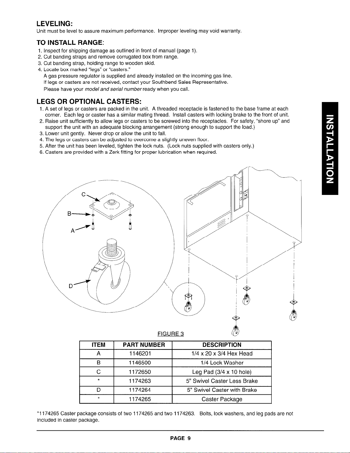
LEGS OR OPTIONAL CASTERS:
1. A set of legs or casters are packed in the unit. A threaded receptacle is fastened to the base frame at each
corner. Each leg or caster has a similar mating thread. Install casters with locking brake to the front of unit.
2. Raise unit sufficiently to allow legs or casters to be screwed into the receptacles. For safety, “shore up” and
support the unit with an adequate blocking arrangement (strong enough to support the load.)
3. Lower unit gently. Never drop or allow the unit to fall.
4. The legs or casters can be adjusted to overcome a slightly uneven floor.
5. After the unit has been leveled, tighten the lock nuts. (Lock nuts supplied with casters only.)
6. Casters are provided with a Zerk fitting for proper lubrication when required.
3
l/4 x 20
ITEM
A
FIGURE
PART NUMBER
1146201
B 1146500
C
*
D
*
*1174265 Caster package consists of two 1174265 and two 1174263.
included in caster package.
1172650
1174263 5” Swivel Caster Less Brake
1174264
5” Swivel Caster with Brake
1174265 Caster Package
PAGE 9
DESCRIPTION
x 3/4 Hex Head
l/4 Lock Washer
Leg Pad (3/4 x 10 hole)
Bolts, lock washers, and leg pads are not
Page 11

w
FIGURE 4
ITEM 1 PARTNUMBER 1 DESCRIPTION
A 1146201
B 1146500
C 1172650
D 1174259
*
*
* 1174260 Leg package consists of four legs. Screws, leg pad, and lock washers are not included in leg package.
* Not shown - these are optional. The leg pad hardware will stay the same.
1174260 Leg Package (set of 4)
1174262
A WARNING
To avoid accidental aas disconnection and potential explosion:
l
For an appliance equipped with casters, the installation should be made with a connector that
complies with the standard for connectors for movable gas appliances, ANSI 221.69 or connectors for movable gas appliances, CAN/CGA-6.1 6, and a quick-disconnect device that complies
with the standard for quick-disconnect devices for use with gas fuel, ANSI 221.41, or quickdisconnect devices for use with gas fuel, CAN1 -6.9.
l
Adequate means must be provided to limit the movement of the appliance without depending on
the connector and the quick-disconnect device or its associated piping to limit the appliance
movement where the restraining means may be attached to the appliance.
114 x 20 x 3/4 Hex Head
II4 Lock Washer
Leg Pad (3/4 x 10 hole)
S.S. Leg (3/4 stud)
Earth Quake Legs SS (set of 4)
A WARNING
To avoid accidental aas disconnection and potential explosion:
If disconnection of this restraint is necessary to move the appliance for cleaning, etc., reconnect
it when the appliance is moved to its originally installed position.
PAGE 10
Page 12

Adequate restraining means “must be attached to rear of appliance when installed.” Installation must conform to local
codes as applicable.
For units not equipped with flame safety devices, be sure all valves are turned off I)TioT to disconnecting. When recon-
necting, be sure all valves are turned off and all pilots are lit.
INSTALLATION INSTRUCTIONS FOR RESTRAINING DEVICE:
1. Restraining device bracket (item ‘IS”) and eye-bolt (item ‘7) should be positioned as closely as possible to the
appliance connector inlet and outlet connections.
2. Secure bracket (item “B”) to a wall stud. Use four each #I2 screws (item “Cl’) and plastic anchors (item “A’) if necessary.
3. Install eye-bolt (item “F”) to a frame member on the rear of the equipment. After checking carefully behind the frame
member for adequate clearance, drill a i/4” hole through the frame member.
NOTICE
l
Extreme caution
the drilling.
l
The location of the drilled hole and the eye-bolt installation should be per the appliance manufac-
turer’s recommendations.
4. Thread hex nut (item “G”) and slide the washer (item “H”) onto the eye-bolt. Insert the eye-bolt through the l/4” drilled
hole and secure with a washer (item “H”) and nylon lock nut (item “I”).
5. Using the spring-loaded snap hooks, attach the restraining device to the bracket and the eye-bolt.
6. Using the cable clamp (item ‘ID”), adjust the restraining device extended length to prevent over-bending or kinking of
the appliance connector.
SEE ADDITIONAL INSTRUCTIONS FURNISHED WITH APPLIANCE CONNECTOR
should be exercised to ensure that no appliance internal parts are damaged by
PAGE 11
Page 13

GRIDDLES:
New griddles should be carefully tempered and maintained to avoid possible cracking and/or warping. To break in a
new griddle, first wipe it clean. Next, light all griddle burners and set thermostats at 200°F for one hour. Then, gradually bring griddle to frying temperature. Next, spread three or four ounces of beef suet or, as a substitute baking soda,
to season it. Never allow water on a hot griddle and never wash it with soap and water.
Use a Norton Alundum (or equivalent) Griddle Brick to clean griddle. Always remember to heat griddle slowly because
quick heat may cause costly damage. Griddle plates cannot be guaranteed against damage due to carelessness.
Never place utensils on griddle. Do not heat griddle above 55O”F, as this will cause warpage or breakage.
Do not use anv tvpe of steel wool, since small particles may be left on the surface and get into food products.
PERFORMANCE CHECK:
The following items should be checked within the first 30 days of operation by a qualified service technician.
1. Verify equipment is level.
2. Verify proper electrical characteristics -- voltage, cycle, phase.
3. Check thermostat operation; calibrate if required.
4. Check ventilation.
5. Check electrical connections -- external and internal.
6. Check door for proper alignment, tension, seal, and adjustment.
7. Check timers, switches and motor for proper installation and operation.
8. Check for any damage to unit from shipping or installation.
9. Check for proper clearance from combustible materials.
10. Verify proper type of gas.
11. Verify gas supply and pressure. (Pressure regulator is already installed at factory.)
12. Check gas connection and check for leaks.
It is common for new products to require a burn-off time to dry out insulation and metal cooking surfaces.
PAGE 12
Page 14

THEORY OF OPERATION
F
D
FIGURE 6
LIGHTING, RE-LIGHTING AND SHUTDOWN INSTRUCTIONS
NOTE: When this range has been disconnected and re-connected to its gas source, light oven first and then
wait six minutes before lighting top section. This allows all air to be purged from the range.
Refer to figure 6 above when following these instructions.
LIGHTING: RANGE CONVECTION OVEN
1. Turn “cook” thermostat to “off.” (item “A”)
2. Turn oven service valve on front of range “on.” (item “B
3. Place power switch in “on” position. (item “C”)
Auto ignition will light pilot.
4. After pilot is lit, turn thermostat to desired setting. (item
“A”)
STANDBY (OVEN NOT IN USE):
1. Place power switch in “off” position. (item “C)
2. Turn thermostat to “off” (item “A”)
RELIGHTING:
Wait 5 minutes and repeat lighting instructions.
FOR COMPLETE SHUTDOWN
1. Place oven power switch in “off” position. (item “C”)
2. Turn oven thermostat to “off.” (item “A”)
3. Turn oven service valve to “off.” (item “B”)
4. Turn all top burner control valves to “off.” (items “D”
and “El’)
LIGHTING: RANGE TOP SECTION
1. Turn all burner control valves to “off.” (items “D” and “E”;
there are 6 knobs on model 300, 4 knobs on model 301)
2. Turn safety valve handle to “pilot,” depress button (item
“G”), light pilot using spark igniter (item “I”) or lighted taper,
and hold for 45 seconds or until pilot remains lit.
3. Turn safety valve handle to “on” (item “HI’). Turn burner
control valves to desired settings (items “D” and “El’).
RELIGHTING:
Raise pull button on safety valve handle and turn to “off.”
(item ‘7) Wait 5 minutes
5. Raise pull button on top section safety valve handle and
turn to “off.” (item “F”)
6. Turn main gas supply valve to “off” (external to range supplied by customer).
and repeat lighting instructions.
PAGE 13
Page 15

A CAUTION
To eliminate aas buildup which could result in exolosion:
In the event of main burner ignition failure, a five minute purge period must be observed prior to
restablishing ignition source.
A DANGER
EXPLOSION HAZARD
In the event a gas odor is detected, shut down equipment at the main shut off valve. Immediately
call the emergency phone number of your gas supplier.
GRIDDLE COOL DOWN:
coat griddle surface with a light film of cooking oil to protect surface from moisture.
At the end of each use, allow griddle
to COOI normally.
After griddle has cooled,
NOTICE
Use of stock pots on griddle can cause surface damage.
NOTICE
Do not clean spatula by hitting the edge on the griddle plate. Such action may cut and pit the griddle
surface, leaving it rough and hard to clean.
A WARNING
BURN OR EXPLOSION HAZARD
Open burners must be installed a minimum of 16” from a deep fat fryer. Splatter of grease into an
open flame can result in fire. Splatter of water into grease can cause explosions and severe burns.
A WARNING
The use of aluminum foil can cause heat distribution problems in ovens. Extreme care must be used
when placing aluminum foil in the oven to ensure that it does not block or change the air flow. The
use of aluminum foil may void the product warranty if its use is ascertained to be a problem.
A WARNING
For an appliance equipped with a convection type oven, no attempt should be made to operate oven
during a power failure.
PAGE 14
Page 16

COOKING TIPS
(CONVECTION-TYPE OVEN ONLY):
A. FROZEN ENTREE PRODUCTS: Punch holes in lid before heating. Tent lid if product has a tendency to stick, i.e.,
lasagna or macaroni and cheese. Use manufacturer’s convection oven directions for time and temperatures or
reduce conventional oven temperature 50” for six half-size pan load. Some products may cook in 10 to 15 minutes
less time than recommended for convection ovens if prepared from frozen in a six pan load.
B. FRUIT PIES: Use temperature and time from manufacturer’s directions for convection ovens for a 12 pie load placed
on three bun pans.
C. ROLLS - YEAST: Use temperature and time recommended by manufacturer for convection ovens for a three pan
load.
D. POTATOES - PRE-BLANCHED, FROZEN: Spread on ungreased bun pans, three pans per load. Bake at 400” F,
stirring once, for 15 to 18 minutes.
E. FISH PORTIONS - BREADED, PRE-COOKED: Use manufacturer’s recommended temperature and time for
convection oven for a three pan load.
F. POTATOES - BAKING, 8 OZ. SIZE: Wash and wrap in potato foil. Place 30 potatoes on 18 by 24 bun pan - three
pans per load. Bake in 400°F oven for 1 hour.
G. TOP ROUND OF BEEF, NO. 168: Set oven at 250” F. Place trimmed roast on pan. For 14-16 pounds:
140°F rare - 14 minutes/pound: 150°F medium - 16 minutes/pound; 160°F well done - 17% minutes/pound.
SUGGESTIONS (CONVECTION-TYPE OVEN ONLY):
If cakes are dark on the sides and not done in the center . . . . . . . . . . . . . . . . . . . . . . . . . . . . . . . . . . . . . . . . . . . . . . . . . . . . . . lower oven temperature.
If cake edges are too
If cakes have light outer color . . . . . . . . . . . . . . . . . . . . . . . . . . . . . . . . . . . . . . . . . . . . . . . . . . . . . . . . . . . . . . . . . . . . . . . . . . . . . . . . . . . . . . . . . . . . . . . .
If cake settles slightly in the center . . . . . . . . . . . . . . . . . . . . . . . . . . . . . . . . . . . . . . . . . . . . . . . . . . . . . . . . . . . . . . . . . . . . . . . . . . . . . . . . . . . . . . . .
If pies have uneven
If meats are browned and
If meats are well done and
If cake ripples . . . . . . . . . . . . . . . . . . . . . . . . . . . . . . . . . . . . . . . . . . . . . . . . . . . . . . . . . . . . . . . . . . . . . . . . . . . . . . . . . . . . . . . . . . . . . . . . . . . . . . . . . . . . . . . . . . . . . . . . .
If there is excessive meat shrinkage . . . . . . . . . . . . . . . . . . . . . . . . . . . . . . . . . . . . . . . . . . . . . . . . . . . . . . . . . . . . . . . . . . . . . . . . . . . . . . . . . . . . .
brown . . . . . . . . . . . . . . . . . . . . . . . . . . . . . . . . . . . . . . . . . . . . . . . . . . . . . . . . . . . . . . . . . . . . . . . . . . . . . . . . . . . . . . . . . . . . . . . . . . . reduce
color . . . . . . . . . . . . . . . . . . . . . . . . . . . . . . . . . . . . . . . . . . . . . . . . . . . . . . . . . . . . . . . . . . . . . . . . . . . . . . . . . . . . . . . . . . . . . . . . . . . . . . .
not done in center . . . . . . . . . . . . . . . . . . . . . . . . . . . . . . . . . . . . . . . . . . . . . . . . . . . . . . . . . . . . . . . . . . . . . . . .
not browned . . . . . . . . . . . . . . . . . . . . . . . . . . . . . . . . . . . . . . . . . . . . . . . . . . . . . . . . . . . . . . . . . . . . . . . . . . . . . . . .
too thin.
lower oven temperature.
number of pans or
lower oven temperature.
raise temperature.
bake longer or raise oven
temperature slightly. Do not
open doors too often for long
periods.
number of pies per
reduce
rack.
lower oven temperature and
roast longer.
raise temperature.
amount of moisture.
overloading
Limit
pans or batter
is
If cakes are too coarse . . . . . . . . . . . . . . . . . . . . . . . . . . . . . . . . . . . . . . . . . . . . . . . . . . . . . . . . . . . . . . . . . . . . . . . . . . . . . . . . . . . . . . . . . . . . . . . . . . . . . . . . . lower oven temperature.
PAGE 15
Page 17

ADJUSTMENTS
NOTICE
Service work should be performed only by a qualified technician who is experienced in, and
knowledgeable of, the operation of commercial gas, electric, and steam cooking equipment.
Contact the Authorized Southbend Service Agency for reliable service, dependable advice
or other assistance, and for genuine factory parts.
Warranty will be void and the manufacturer is relieved of all liability if:
(A) Service work is performed by other than a qualified technician.
(B) Other than genuine Southbeniyeplacement parts are installed.
i
Refer to figure 7 (above).
/
FIGURE 7
PILOT ADJUSTMENTS:
A. Remove the pilot adjust cover screw located at the pilot gas outlet on safety valve.
B. Using a screwdriver, turn pilot adjusting screw to the right to decrease or left to increase the size of the pilot
flame. (Flame should cover thermocouple tip, approximately i/2.“)
C. Replace pilot adjustment cover screw.
PAGE 16
Page 18

ADJUSTMENTS
FIGURE 8
Refer to figure 8 (above).
OVEN PILOT:
A. Remove the kick panel below the oven door (item “A”).
B. Adjust oven pilot flame by turning the adjusting screw on the pilot line valve (item “B”).
C. The pilot flame is properly adjusted when it is just large enough to maintain a glowing red color of the flame
switch capillary bulb.
PAGE 17
Page 19

GENERAL:
TROUBLE SHOOTING
OVEN:
PROBLEM -
All burners and pilots in unit
will not turn on
All burners produce excessive
carbon deposits
Only some burners in a unit
produce excessive carbon
deposits
Only some pilots produce
excessive carbon deposits
Top burner (not oven) will
not come on
Top section pilot will not
stay ignited
PROBLEM - CHECK OR REPLACE -
LOOK FOR Main gas supply to unit is “OFF”
Incorrect gas type supplied to unit
Incorrect supply pressure
Incorrect orifices
Primary air not adjusted properly
Pilot gas not adjusted properly
Incorrect pilot orifice
Manual valve for top burner in “OFF” position
Pilot out
Pilot gas not adjusted properly
Clogged orifice
Draft condition
Improper ventilation system
Air in gas line
Unit does not come on when
“Power Switch” is in the
“On” position
Motor will not run with
fan switch in any position
Motor will not run in “Bake”
position but runs in ‘Cool”
position
No spark at pilot Spark igniter
Spark present but standing;
pilot will not light
Pilot ignites but burners will
not light when thermostat
calls for heat;
cook light on
Unit will function properly for
a period of time and then shut
down (oven circulating blower
and oven burners). Oven will
begin to function properly again
after it has cooled down.
Power cord is plugged in
Main supply fuses
Unit power switch
Fan switch
Motor
Door switch actuator
Door switch
Wire to spark electrode broken or
disconnected
Gas supply to unit shut off
Unit gas line shutoff in closed position
Pilot line valve in closed position
Pilot line solenoid
Main gas solenoid
Flame switch bulb in correct position
Flame switch
Motor overheating
Pilot ignites but burners and
cook light will not come on
when thermostat calls for heat
Thermostat
PAGE 18
Page 20

MAINTENANCE
A WARNING
SHOCK HAZARD
De-energize all power to equipment before cleaning the equipment.
At least twice a year, have your Southbend Authorized Service Agency or another qualified service technician clean
and adjust the unit for maximum performance.
Consult the Southbend Authorized Parts/Service Distributor list for the Authorized Service Representative in your
area. If this is not available, call the Service Department at Southbend, i-800-348-2558 for their name and number.
A WARNING
Adjustments and service work may be performed only by a qualified technician who is experienced in,
and knowledgeable with, the operation of commercial gas cooking equipment. However to assure
your confidence, contact your authorized Southbend service agency for reliable service, dependable
advice or other assistance, and for genuine factory parts.
Southbend equipment is sturdily constructed of the best quality materials and is designed to provide durable service
when treated with ordinary care. To expect the best performance, your equipment must be kept in good condition and
cleaned daily. Naturally, the periods for this care and cleaning depend on the amount and degree of usage.
MAINTENANCE - ALL UNITS - EXTERIOR AND TOP SECTIONS:
Keep exposed, cleanable areas of unit clean at all times.
DAILY:
A. Remove, empty, and clean grease drawers and dirt trays.
B. Clean griddle drain chutes.
MONTHLY:
A. Clean around burner air mixers and orifices if lint has accumulated.
B. Visually assure proper pilot operation.
Vent System: At least twice a year, the unit venting system should be examined and cleaned.
Following daily and periodic maintenance procedures will enhance long life for your equipment.
salt air - may require more thorough and frequent cleaning or the life of the equipment could be adversely affected.
STAINLESS STEEL:
1. To remove normal dirt, grease, and product residue from stainless steel that operates at LOW temperature, use
ordinary soap and water with or without detergent, applied with a sponge or cloth. Dry thoroughly with a clean
cloth.
2. To remove grease and food splatter or condensed vapors that have baked on to the aphly clestter
Climatic conditions -
Page 21
Little attention is needed, but if spillage should occur, it may be necessary to clean around pilot areas, air mixer and
under burners. Use a wire brush if necessary.
Periodically, burners (particularly open top type) should be removed and cleaned. Allow interior to completely drain.
Dry thoroughly before replacing.
HOT TOPS:
Allow range to cool. If water is used on tops while still hot, they may crack. Avoid this practice. Remove tops from
range and clean surfaces with hot water and detergent. A wire brush may be used on the underside of the Hot Top
plate. It is recommended not to clean tops while still on range, even if cooled, as excessive water will drip into the burner box and deteriorate the metal.
Do not waste gas and abuse equipment by leaving all burners “Full On” if not required. During idling periods, adjust
burner valves to keep top warm.
CARE OF GRIDDLES:
New griddles should be carefully tempered and cared for in order to avoid possible damage. To break in a new griddle,
first wipe it clean. Next, light all the griddle burners and turn them low for one hour. Then, gradually bring griddle to fry-
ing temperature. Next, spread three or four ounces of beef suet, or as a substitute, baking soda, to season it. Never
allow water on a hot griddle and never wash it with soap and water.
Use a Norton Alundum Griddle Brick to clean griddle. Always remember to heat griddle slowly because quick heat may
cause costly damage. Griddle plates cannot be guaranteed against damage due to carelessness. Never place utensils
on griddle. Do not heat griddle above 55O”F, as this can cause warpage or breakage.
Re-adjust burner valves as required for periods of heavy loads.
Do not use any type of steel wool. Small particles may be left on the surface and get into food products. Do not clean
spatula by hitting the edge on the griddle plate. Such action will only cut and pit the griddle plate, leaving it rough and
hard to clean.
Do not waste gas or abuse equipment by leaving valves at “Full On” position or thermostat at a high temperature if not
required. During idle periods, set valves at “Low” position or thermostat to low temperature settings to keep griddle
warm. Reset valves or thermostats, as required, for periods of heavy load. Turn valves or thermostats to “off” at end of
daily operation.
OVEN INTERIOR:
A WARNING
For your safety, disconnect the power supply to the appliance before cleaning.
Oven bottom and oven door lining are finished with a porcelain enamel coating which encourages frequent cleaning.
“Spill-avers” should be cleaned from the oven bottom and the door lining a soon as possible to prevent carbonizing and
“burnt-on” condition. Usually, a soap or detergent solution is strong enough. For stubborn accumulations, commercial
oven cleaners are recommended.
The side, rear and top linings have an aluminized coating and should be cleaned with a sponge or cloth and a mild
detergent. Do not use a strong commercial cleaner or abrasive pad, as they may damage the finish.
The rack slides are readily removable for ease in cleaning. To remove, raise them and they will become disengaged
from their hanger studs. After cleaning, reverse procedure to reinstalE5 0 TD 3 Tr279.7704Tr21.840 TD 3 Tr -0.0086 Tc 007840 Tw Fo(regne ) Tj0 Tr 375774 0 TD 3 Tr -0.06 Tc 00.910 Tw matfter
Page 22

CONTROL PANEL:
The textured control panel should be cleaned with warm water and mild soap. Never use cleaning solvents with a hydro-
carbon base.
MOTOR:
Lubrication information can be found on a permanent label located on motor.
A CAUTION
DO NOT USE ordinary steel wool as any particles left on the surface will rust.
NEVER USE a wire brush, steel or abrasive scouring pad (except stainless), scraper, file or other steel
tools. Surfaces which are marred collect dirt more rapidly and become more difficult to clean. Marring
also increases the possibility of corrosive attack.
DO NOT clean door gasket with a high chlorine solution or bleach.
NEVER use any corrosive cleaner. Use only cleaners approved for stainless steel.
A WARNING
Improper cleaning can result in expensive repairs or electrical shock. Do not get water on electrical
controls or motors.
PAGE 21
Page 23

PARTS -- ACCESSORIES
NOTICE
INSTALLATION OF OTHER THAN GENUINE SOUTHBEND PARTS WILL VOID THE
WARRANTY ON THIS EQUIPMENT.
I
The serial plate with voltage, model, and serial information is located below oven door, behind the kick panel attached to frame
base of oven. There is also an Identification Plate mounted to the front left corner of the valve panel that will supply model and
serial number.
Replacement parts may be ordered either through a Southbend Authorized Parts Distributor or a Southbend Authorized Service
Agency.
When ordering parts, please supply the Model Number, Serial Number, Part Number, Description, Finish, and Electrical
Characteristics as applicable.
I
Consult the Southbend Authorized Parts/Service Distributor list for the Authorized Parts supplier in your area.
available, call the Service Department at Southbend, l-800-348-2558 for same.
If this list is not
PAGE 22
Page 24

Refer to figure 9 above.
iJRE 9
* Item not shown on drawing.
PART NUMBER
PAGE 23
I
DESCRIPTION
Page 25

Refer to figure IO above.
* Item not shown on drawing.
FIGURE
PART NUMBER DESCRIPTION
PAGE 24
10
Page 26

LIMITED WARRANTY
Southbend warrants that the equipment, as supplied by the factory to the original purchaser, is free from defects in materials
and workmanship. Should any part thereof become defective as a result of normal use within the period and limits defined
below, then at the option of Southbend, such parts will be repaired or replaced by Southbend or its Authorized Service
Agency. This warranty is subject to the following conditions.
Repairs under this warranty are to be performed only by a Southbend Authorized Service Agency. Southbend cannot be
responsible for charges incurred or service performed by non-Southbend Authorized Service Agencies. In all cases the closest Southbend Authorized Service Agency must be used.
TIME PERIOD:
One year labor, one year parts effective from the date of original purchase. The authorized service agency may at his option
require proof of purchase.
Exceptions to standard warranty, effective within above limitations:
l
Glass Windows, Door Seals, Rubber Seals, Light Bulbs, Ceramic Bricks
l
Sight Glasses, Cathodic Descalers or Anodes, Broiler Briquettes and Drip Shields. 90 days material and labor
l
Stainless Steel Fry Pot. . . . . . . .4 years extended material warranty on fry pot only -- no labor
l
Stainless Steel Open Top Burners. . . 4 years extended material warranty on burners only -- no labor
l
Pressure Steam Boiler Shell . . Prorated 4 years extended warranty on boiler shell only -- no labor
Boiler she//s which have not been properly maintained will not be covered by warranty.
In all cases, parts covered by a five-year warranty will be shipped FOB Factory after the first year.
EXCLUSIONS:
The following conditions are not covered by warranty:
l
Equipment failure relating to improper installation. Examples are: improper utility connection, improper utilities supply and
problems due to ventilation.
l
Equipment that has not been properly maintained. Examples are: calibration of controls, adjustments to pilots and burn-
ers, damage from improper cleaning, and water damage to controls.
l
Equipment that has not been used in an appropriate manner, or has been subject to misuse or misapplication, neglect,
abuse, accident, damage during transit or delivery, fire flood, riot or act of God.
If the equipment has been changed, altered, modified or repaired by other than a qualified service technician during or after
the one-year limited warranty period, then the manufacturer shall not be liable for any damages to any person or to any property which may result from the use of the equipment thereafter.
Equipment failure caused by inadequate water quality is not covered under warranty. WATER QUALITY must not exceed the
following limits: Total Dissolved Solids (TDS) - 60 PPM (Parts Per Million). Hardness - 2 Grains or 35 PPM, pH Factor - 7.0 to
7.5. Water pressure 30 PSI minimum, 60 PSI maximum. Boiler maintenance is the responsibility of the owner and is not covered by warranty.
This warranty does not cover services performed at overtime or premium labor rates nor does Southbend assume any liability
for extended delays in replacing or repairing any items in the equipment beyond the control of Southbend, “Southbend shall
not be liable for consequential or special damages of any nature that may arise in connection with such product or part.”
Should service be required at times which normally involve overtime or premium labor rates, the owner shall be charged for
the difference between normal service rates and such premium rates.
This warranty only covers product shipped into the 48 contiguous United States and Hawaii. There will be no labor coverage
for equipment located on any island not connected by roadway to the mainland.
This equipment is intended for commercial use only. Warranty is void if equipment is installed in other than commercial application.
Warranty on all replacement parts which are replaced in the field by Southbend Authorized Service Agencies will be limited to
three months on labor, six months on materials (parts) effective from the date of installation. See LIMITED WARRANTY REPLACEMENT PARTS for conditions and limitations.
“THE FOREGOING WARRANTY IS IN LIEU OF ANY AND ALL OTHER WARRANTIES EXPRESSED OR IMPLIED INCLUD-
ING ANY IMPLIED WARRANTY OF MERCHANTABILITY OR FITNESS, AND CONSTITUTES THE ENTIRE LIABILITY OF
SOUTHBEND. IN NO EVENT DOES THE LIMITED WARRANTY EXTEND BEYOND THE DURATION OF ONE YEAR
FROM THE EFFECTIVE DATE OF SAID WARRANTY.”
Consult the Southbend Authorized Parts/Service Distributor list for the Authorized Service Representative in your area.
If this list is not available, call the Service Department at Southbend, I-800-348-2558.
PAGE 25
Page 27

A product with the Southbend name incorporates the best in durability
and low maintenance. We all recognize however, that replacement parts
and occasional professional service may be necessary to extend the
useful life of this unit. When service is needed, contact a Southbend
Authorized Service Agency, or your dealer. To avoid confusion, always
refer to the model number, serial number, and type of your unit.
m southbend
A MIDDLEBY COMPANY
PART NUMBER 1177047
0 1995 SOUTHBEND PRINTED USA 05/95
SOUTHBEND
REGISTERED TO IS0 9001
CERTIFICATE NO. A2062
Certification No. FM25780
Southbend Registered to IS0 9001
1100 Old Honeycutt Road
Fuquay-Varina, NC 27526
(919) 552-9161
FAX (919) 552-9798
(800) 348-2558
 Loading...