

Page 1

OPERATOR’S MANUAL
Free-Standing, Floor Model
4FR-45 Restaurant Range Fryer
MANUAL 1182128
$10.00
4FR-45 RESTAURANT RANGE FRYER
MANUAL SECTION SR
Page 2
4FR-45 RESTAURANT RANGE FRYER
Safety Precautions
Before installing a nd opera ting this equipm ent, be sure e ver yone invol ved in its operat ion is f ully tr ained and
aware of precautions. Accidents and problems can be caused by failure to follow fundamental rules and
precautions.
The following s ymbols, found throughout this manual, alert you to potentia lly dangerous conditions to the
operator, service personnel, or to the equipment.
! DANGER
! WARNING
! CAUTION
NOTICE
This symbol warns of immediate hazards that will result in severe injury or
death.
This symbol refers to a potential hazard or unsafe practic e that could result in
injury or death.
This symbol refers to a potential hazard or unsafe practice that could result in
injury, product damage, or property damage.
This symbol refers to information that needs special attention or must be fully
understood, even though not dangerous.
! WARNING
FIRE HAZARD
FOR YOUR SAFETY
Do not store or use ga soline or other flamm able vapors and l iquids in the vicinit y of this or an y other
appliance.
Keep area around appliances free and clear of combustibles.
Purchaser of equipment m ust post in a prom inent location, d etailed instruc tions to be f ollowed in the
event the operator smells gas. Obtain the instructions from the local gas supplier.
! WARNING
BURN HAZARD
Contact with hot oil will cause sever e b urns . A l wa ys use c a uti on. O il at 2 0 0°F is more dangerous than
boiling water.
! WARNING
In the event a gas odor is de tected, shut down equ ipment at the com bination gas valv e and contact
the local gas company or gas supplier for service.
NOTICE
The Southbend 4FR-45 Restaurant Range Fryer is intended for commercial use only. Not for
household use.
Warranty will be void if servic e work is perfor med b y other than a qualif ied techn ician, or if other th an
genuine Southbend replacement parts are installed
Be sure this Operator’s Man ual and important papers ar e given to the proper authorit y to retain for
future reference.
PAGE 2OPERATOR’S MANUAL 1182128
Page 3

4FR-45 RESTAURANT RANGE FRYER TABLE OF CONTENTS
Congratulations! You have purchased on e of the finest p ieces of heav y-duty comm ercial cook ing equipm ent
on the market.
You will find that your new equipm ent, like all Southbend equipment, has been desig ned and m anufactured
to meet the toughest standards in the indus try. Each piece of Southbend equipm ent is carefully eng ineered
and designs are verified through laboratory tests and field installations. With proper care and field
maintenance, you will experience years of reliable, trouble-free operation. For best results, read this
manual carefully.
RETAIN THIS MANUAL FOR FUTURE REFERENCE.
Model Number
This manual is for the Southbend Free- Standing, Floor Model, 4F R-45 Restaurant Ra nge Fryer. The seri al
plate is located inside the front door on the left side.
Table of Contents
Specifications..........................................................................................................................4
Installation...............................................................................................................................6
Operation ..............................................................................................................................12
Cooking Hints........................................................................................................................15
Cleaning................................................................................................................................17
Service..................................................................................................................................20
Parts......................................................................................................................................25
Read these instructions carefully before attempting installation. Installation and initial startup should be
performed by a qualified installer. Unless the installation instructions for this product are followed by a
qualified service tech nician (a person experienced in and knowledge able with the insta llation of comm ercial
gas an/or electric cooking equipm ent) then the terms and conditi ons on the Ma nufactur er’s Lim ited W arranty
will be rendered void and no warranty of any kind shall apply.
In the event you have questions concerning the installation, use, care, or service of the product, write to:
Technical Service Department
Southbend
1100 Old Honeycutt Road
Fuquay-Varina, North Carolina 27526 USA
OPERATOR’S MANUAL 1182128 PAGE 3
Page 4
SPECIFICATIONS 4FR-45 RESTAURANT RANGE FRYER
A
p
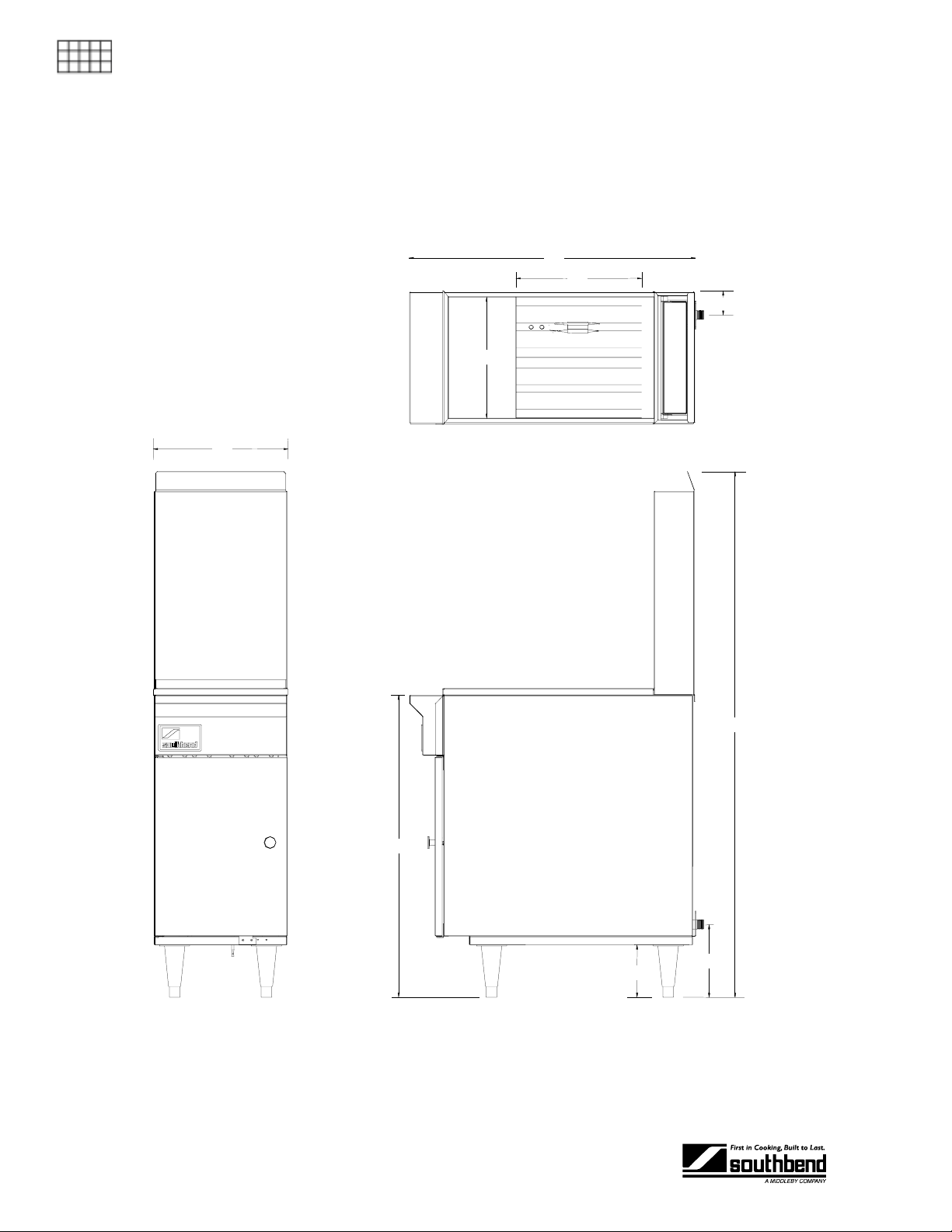
SPECIFICATIONS
SPECIFICATIONS
Dimensions
C
D
H
B
To
View
F
G
Front View Side View
PAGE 4OPERATOR’S MANUAL 1182128
E
I
Page 5
4FR-45 RESTAURANT RANGE FRYER SPECIFICATIONS
Gas Supply Requirements and Burner Information
Supply pressure should be greater t han 7" W.C. for natural gas or greater than 11" W .C. for propane. One
3/4" NPT male connector is located on the back of the fryer (see illustrations on pages 4 and 7).
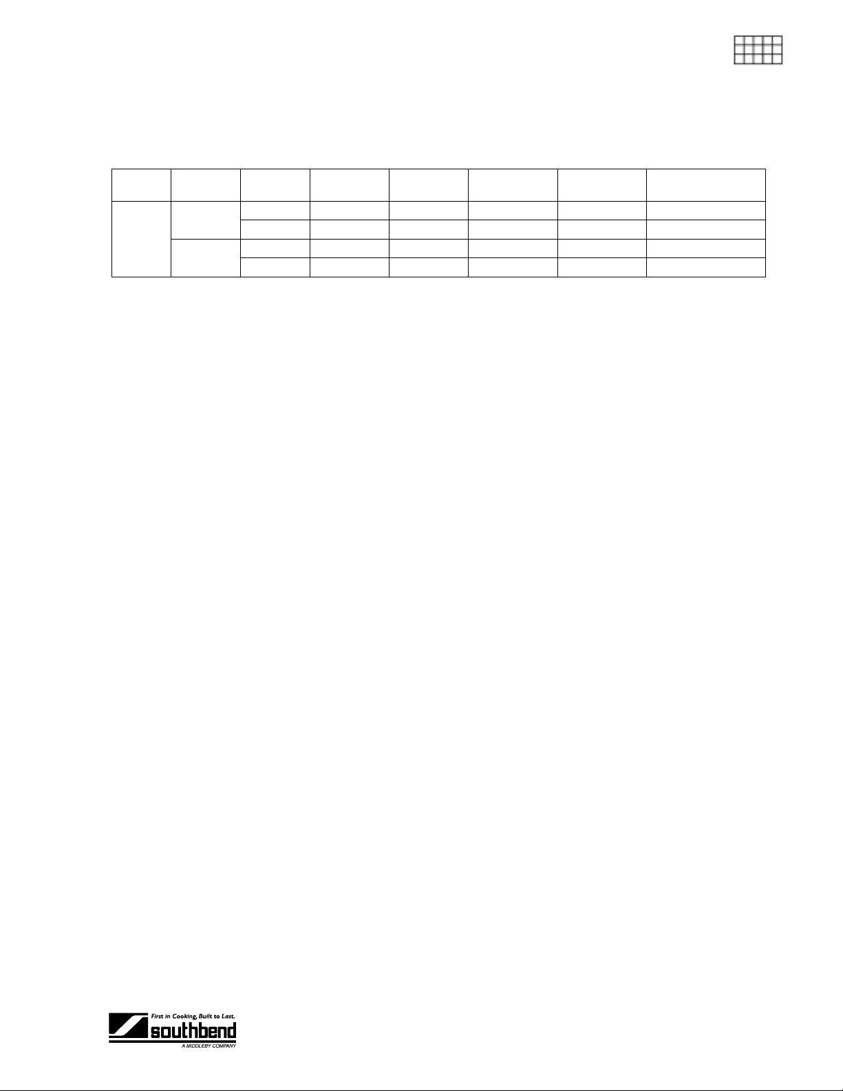
SPECIFICATIONS
Model Burners Gas Type
Main
4FR-45
Pilot
Natural 4" W.C. 4 35,000 140,000 #36 - 0.1065" dia.
Propane 10" W.C. 4 30,000 120,000 #52 - 0.0635" dia.
Natural 4" W.C. 1 900 900 #77 - 0.0180" dia.
Propane 10" W.C. 1 900 900 0.0110" dia.
Manifold
Pressure
Electrical Requirement
No external electric power is required.
Clearances
See page 9.
Number
per Unit
Rate Each
BTUs/Hour
Total Rate
BTUs/Hour
Orifice Size
OPERATOR’S MANUAL 1182128 PAGE 5
Page 6
INSTALLATION 4FR-45 RESTAURANT RANGE FRYER
INSTALLATION
Installation mu st conform with local codes, or in the absence of local codes , with the National Fue l
Gas Code, ANSI Z223.1, Natural Gas Installation Code, CAN/CGA-B149.1, or the Propane
Installation Code, CAN/CGA-B149.2, as applicable.
INSTALLATION
These installation procedures must be followed by qualified personnel or warranty will be void.
Local codes regarding install ation var y greatly from one area to an other. T he National F ire Protec tion
Association, Inc. states in its NFPA 96 latest edition that local codes are the “authority having
jurisdiction” when it comes to installation requirements for equipment.
NOTICE
NOTICE
Step 1: Unpack
IMMEDIATELY INSPECT FOR SHIPPING DAMAGE
All containers shou ld be examined for dam age before and during unlo ading. The freight car rier has
assumed responsibility for safe transit and delivery. If damaged equipment is received, either
apparent or concealed, a claim must be made with the delivering carrier.
Apparent damage or l oss m u st be noted on the freight b ill at the t im e of deliver y. T he f reight bi ll m ust
then be signed by the c arrier representative (Dr iver). If the bill is not signed, the carrier ma y refuse
the claim. The carrier can supply the necessary forms.
A request for insp ection must be m ade to the carrier within 15 da ys if there is concea led damage or
loss that is not apparent until after the equipment is uncrated. The carrier should arrange an
inspection. Be certain to hold all contents plus all packing material.
1. Uncrate carefully. Report any hidden damage to the freight carrier IMMEDIATELY.
2. Do not remove any tags or labels until unit is installed and working properly.
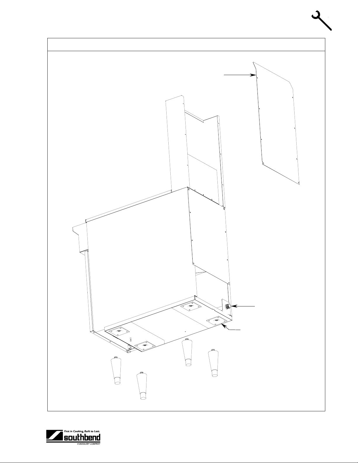
Step 2: Install Flue Riser
The flue riser assembl y is packed separately in the f ryer shipping crate. Att ac h t he flue riser to the top rear of
the fryer (see illustration on page 7).
PAGE 6OPERATOR’S MANUAL 1182128
Page 7
4FR-45 RESTAURANT RANGE FRYER INSTALLATION
r
Installation
Flue Rise
INSTALLATION
Gas Connection
Leg Attachment Pad
OPERATOR’S MANUAL 1182128 PAGE 7
Page 8
INSTALLATION 4FR-45 RESTAURANT RANGE FRYER
Step 3: Install the Legs (or Casters) and Restraints
A set of legs or casters is packed with the fryer. A threaded pad is fastened to the base frame at each corner
(see illustration on page 7). Each leg or caster has a similar mating thread. When casters have been
ordered, the casters are provided with a Zerk fitting for proper lubrication when required.
1. Raise fryer suffic iently to allow legs or c asters to be scr ewed into the pads. For s afety, “shore up” an d
support the fryer with an adequate blocking arrangement strong enough to support the load.
2. Screw the four legs or casters to the pads on the b ottom of the fr yer. When c asters have been order ed,
the casters having a locking-brake should be attached under the front of the fryer.
3. Lower the fryer gently. Never drop or allow the fryer to fall.
4. Use a level to make sure that the fryer is level. Each caster, or the tubular-end of each leg, can be
INSTALLATION
screwed in or out to lower or raise each c orner of the fryer. For f ryers having casters, t ighten the lock
nuts after the unit has been leveled.
5. Attac h res tr aints as requ ir ed b y local cod es .
NOTICE
Unit must be level to assure maximum performance. Improper leveling may void warranty.
NOTICE
Adequate restraining means must be attached to rear of appliance when installed. Installation must
conform to local codes as applicable.
! WARNING
If disconnection of the restraint is necessar y to move the appliance for cleaning, etc., reconnect it
when the appliance is moved to its original installed position.
! WARNING
For an appliance e quipp ed with cas ter s, the ins tall ation sh all b e m ade with a co nnector that com plies
with the Standard for Connectors for Movable Gas Appliances, ANSI Z21.69 or Connectors for
Moveable Gas Appliances, CAN/CGA-6.16, and a quick-disconnect device that complies with the
Standard for Quick-Disconnect Devices for Use With Gas Fuel, ANSI Z21.41, or Quick Disconnect
Devices for Use with Gas Fuel, CAN1-6.9. Adequate means must be provided t o lim it the m ovement
of the appliance without depending on the connector and the quick-disconnect device or its
associated piping to limit the appliance movement.
! WARNING
The 4FR-45 Restaurant Range Fryer must be restrained to prevent tipping in order to avoid the
splashing of hot liquid. The means of restraint m ay be the manner of installat ion, such as c onnection
to a battery of applia nc es or i ns talli ng t he fryer in an alcove, or by se par at e means, such as ad equ ate
ties.
PAGE 8OPERATOR’S MANUAL 1182128
Page 9
4FR-45 RESTAURANT RANGE FRYER INSTALLATION
Step 4: Check Clearances and Ventilation
Select a firm, level loc ation for your Southb end fryer. Leave clear ance, whenever possible, s o that access
from the rear is possible to permit clean ing. If the unit is to be s et on non-combustible flo oring, such as a
concrete slab, 3 inches minim um toe room must be provided t o prevent restriction of t he air opening in the
bottom of the unit.
! WARNING
There must be adequate clearance between fryer(s) and construction. Clearance must also be
provided in front for servicing and for operation.
Minimum Clearances:
From Combustible Construction From Non-Combustible Construction
Sides 7" 0"
Rear 7" 0"
THE 4FR-45 RESTAURANT RANGE F RYER SHALL BE INSTALLED W ITH AT LEAST A 16 INCH
SPACE BETWEEN THE FRYER AND SURFACE FLAMES FROM ADJACENT EQUIPMENT.
No additional side and rear clearance is required for service as the fryer is serviceable from the front.
INSTALLATION
! WARNING
Improper ventilation can result in personal injury or death. Ventilation that fails to properly remove f lue
products can cause headaches, drowsiness, nausea, or could result in death.
All units must be installed in such a manner that the flow of combustion and ventilation air is not
obstructed. Provisions for adequate air supply must also be provided. Do NOT obstruct the bottom
front of the unit, as combustion air enters through this area. Be sure to inspect and clean the
ventilation system according to the ventilation equipment manufacturer’s instructions.
NOTICE
Proper ventilation is t he owner’s responsibility. An y problem due to improper venti lation will not be
covered by the warranty.
Due to the variety of problems that c an be ca us ed b y outside weather condit io ns , ve nt ing by canopies or wall
fans is preferred over any type of direct venting. It is recommended that a canopy extend 6" past the
appliance and the bottom edge be located 6'6" from the floor. Filters should be installed at an angle of 45° or
more from the horizontal. This position prevents dripping of grease and facilitates collecting the run-off
grease in a drip pan, usual ly installed with a filter. A s trong exhaust fan tends to create a vacuum in the
room and may interfere with burner performance or may extinguish pilot flames. Fresh air openings
approximately equal to the fan area will relieve such a vacuum . In case of unsatisfactor y performance on
any appliance, chec k the appliance with the exhaust f an in the “OFF” position. Do th is only long enough to
check equipment perform ance, then turn hood bac k on and let it run to remove any exhaus t that may have
accumulated during the test.
The exhaust fan should be installed at least 2 feet above the vent opening at the top of the fryer.
This unit is not intended to be connected directly to an outside flue.
OPERATOR’S MANUAL 1182128 PAGE 9
Page 10
INSTALLATION 4FR-45 RESTAURANT RANGE FRYER
Step 5: Gas Connection
A 3/4" male NPT line for the gas connection is located near the lower left rear corner of the fryer (see
illustration on page 7). T he ser i al pla te ( loc ate d i ns ide th e front door of the fryer) indicates the type of gas the
unit is equipped to burn (natural gas or propa ne). The f ryer shou ld be c onnec ted O NLY t o the t ype of gas f or
which it is equipped.
A millivoltage circuit diagram is located inside the front door of the fryer, and on page 24 of this manual.
All Southbend equ ipment is adjusted at the f actory; however, pilot he ight should be c hecked at instal lation
and adjusted, if necessary (see page 22).
For orifice sizes and pressure regulator settings, see the chart on page 5. If the fryer is being installed at over
2,000 feet altitude and that inform ation was not specified when order ed, contact the appropr iate authorized
Southbend Service Representative or the Southbend Service Department. Failure to install with proper
orifice sizing will result in poor performance and may void the warranty.
INSTALLATION
If applicable, the ven t line from the gas appliance pressure regulator shall be installed to the outdoors in
accordance with local codes or, in the absence of local codes, with the National Fuel Gas Code, ANSI
Z223.1, Natural Gas Installation Code, CAN/CGA-B149.1, or the Propane Installation Code, CAN/CGAB149.2, as applicable.
An adequate gas supply is imperative. Undersized or low pressure lines will restrict the volume of gas
necessary for satisfac tory performance. A com bination gas valve an d pressure regulator, which is provide d
with each unit, is set to maintain a 4 " W.C. manifold press ur e f or natural gas or 10.0" W.C. manifold pres s ure
for propane gas. However, to mainta in these conditions the press ure on the supply line, wh en all units are
operating simultaneously, should not drop below 7" W.C. for natural gas or 11" W.C. for propane gas.
Fluctuations of m ore than 25% on nat ural gas or 1 0% on pr opan e gas will cr eate pro blem s and aff ect bur ner
operating characteristics. A 1/8" tap to measure the manifold pressure is located on the combination gas
valve, which is on the burner manif old loca ted dir ectly below the burners inside the cab in et.
Purge the supply line to clean out dust, dirt, or other foreign matter before connecting the line to the unit.
It is recommended that an individual manual shutoff valve be installed in the gas supply line to the unit.
Use pipe joint compound that is suitable for use with both natural and LP gas on all threaded connections.
! CAUTION
ALL PIPE JOINTS AND CONNECTIONS MUST BE TESTED THOROUGHLY FOR GAS LEAKS.
USE ONLY SOAPY W ATER FOR TESTING O N ALL GASES. NEVER USE AN O PEN FLAME T O
CHECK FOR GAS LEAK S. ALL CONNECTIONS MUST BE CHEC KED FOR LEAKS AFTER T HE
UNIT HAS BEEN PUT INTO OPERATION. TEST PRESSURE SHOULD NOT EXCEED 14" W.C.
! CAUTION
THIS APPLIANCE AND ITS INDIVIDU AL COMBINATION GAS VALV E MUST BE DISCONNE CTED
FROM THE GAS SUPPLY PIPING SYSTEM DURING ANY PRESSURE TESTING OF THAT
SYSTEM AT TEST PRESSURES IN EXCESS OF 1/2 PSIG (3.45 kPa).
The appliance must be isolated from the gas supply piping system by turning the combination valve to
the OFF position during any pressure test ing of the gas supply pip ing system at test pressures eq ual
to or less than 1/2 psi (3.45 kPa).
Connect the gas suppl y direc tly to th e 3/4" m ale NPT connector locat ed near the lower left r ear corn er of the
fryer. When tighten ing the s u pp l y pipe, be s ure to hol d th e mating connector ex ten din g f r om the unit securely
with a wrench. This will prevent any damage or distortion to the internal piping and controls of the unit.
After connecting the gas suppl y, check again that the fryer is level. Use a long spirit lev el four ways; ac ross
the front and rear of the frypot, and along each edge.
PAGE 10 OPERATOR’S MANUAL 1182128
Page 11

4FR-45 RESTAURANT RANGE FRYER INSTALLATION
! CAUTION
IF YOU SMELL GAS DURING THE LIGHTING PROCE DURE, I MMEDIAT ELY SHUT OFF THE GAS
SUPPLY UNTIL THE LEAK HAS BEEN CORRECTED.
INSTALLATION
OPERATOR’S MANUAL 1182128 PAGE 11
Page 12

OPERATION 4FR-45 RESTAURANT RANGE FRYER
OPERATION
NOTICE
These procedures mus t be followed b y qual if ied pers onn el or warranty will be voided.
The Southbend 4FR-45 Restaura nt R ang e Fr yer is an im mersion tube fryer. T his is the most eff icient method
of transmitting heat into the oil. The tubes are actually large heat exchangers. Each tube is heated by a
burner at its front that propels its f lame and heat i nto the tube, to ward the re ar, where it is vented int o a flue
box. The combined heat transfer area of the tubes is muc h greater than the oth er types using element coils
or under-fired pots. C onse quentl y, heat transf er per s quare i nch is lo wer, as is the tem peratur e, b ut b ecaus e
of the increased surface area, immersion tube fryers transfer more heat into the oil. The lower temperature of
the heating surfac e prevents scorching and carbonizatio n of the oil. Higher heat trans fer rate gives faster
recovery between loads.
Another advantage of immersion tube fryers is the cold zone. As oil is heated it passes between and over the
tubes and rises into th e frying zone, where it imparts heat into the pr oduct. After gi ving up heat , it des cends
to the cooler zone be low the tub es. Foo d particl es and cr umbs are dropped and trap ped in the cold zone as
the oil awaits to be recirculated. The cold zone concept helps keep the oil circulating and clean of debris.
OPERATION
! WARNING
BURN HAZARD
Contact with hot oil will cause sever e b urns . A l wa ys use c a uti on. O il at 2 0 0°F is more dangerous than
boiling water.
! CAUTION
NEVER OPERATE THE FRYER WITHOUT SUFFICIENT OIL TO COVER THE TUBES.
Lighting
! CAUTION
IF YOU SMELL GAS DURING THE LIGHTING PROCE DURE, I MMEDIAT ELY SHUT OFF THE GAS
SUPPLY UNTIL THE LEAK HAS BEEN CORRECTED.
Open the burner compartment door and do the following:
1. Turn thermostat to “OFF” (lowest position).
2. Press down the knob of the combination gas
valve, turn it counterclockwise to the “PILOT”
position, and continue to press the knob down.
PAGE 12 OPERATOR’S MANUAL 1182128
Page 13

4FR-45 RESTAURANT RANGE FRYER OPERATION
3. W hile pressing the knob down, us e a lit match to ignite the pilot. Continue to press the knob d own for
about 30 seconds. If the pilot does not stay ignited when the knob is released, repeat the lighting
procedure and keep the knob down longer. Adjustment of pilot flame may be necessary.
4. W hen the pilot sta ys ignit ed, tur n the k nob cou nterc lock wise to the “ON” posit ion. Do not pres s do wn on
the knob in this step.
5. Do NOT turn the thermostat “ON” until the frypot is filled with oil or solid shortening.
Shutdown Procedure
Standby: Turn knob on the combination gas valve to the “PILOT” position. At this setting, only the pilot
burner will remain ignited.
Complete Shutdown: Turn knob on the com bination gas val ve, then press d own on the knob and co ntinue
to turn to the “OFF” position.
Relighting
! WARNING
In the event of a m ain burner ignitio n f ailure, a five m inute purge peri od m us t be obser ved prior to reestablishing the ignition source.
OPERATION
1. Shut off all gas.
2. Wait five minutes.
3. Follow the “Lighting” procedure described on page 12.
Filling the Frypot
1. Close drain valve completely before filling the frypot.
2. When the fryer is new, fill t he f rypot with water and cl ean thor oug hly (see “W eekly Clean ing” on p age 18)
in order to remove protective coatings and any foreign matter.
3. The recommended solid shortening capacity for the frypot is 45 pounds.
4. Remove the basket support frame when filling the frypot with solid shortening.
5. When solid shortening is used, be careful not to bend, break, or twist the thin capillary wires of the
sensing elements located in the right-hand front corner of the frypot.
6. Pack solid shortening int o the zone below the tubes, all sp aces between the tu bes, and at least a n inch
above the top of the tubes before lighting the fryer. If any air spaces are left around the heat tube
surfaces when the he at is turned on, the tube surf aces will become red hot, burn the soli d shortening,
weaken the frypot, and could result in a fire.
! CAUTION
NEVER ATTEMPT TO MELT A SOLID BLOCK OF SHORTENING ON TOP OF THE HEAT TUBES.
NEVER START THE BURNERS WHEN THE FRYPOT IS EMPTY.
7. To prevent burn ing or scor ching the sol id shortening, keep th e therm ostat set at the lo west tem perature
until all the solid shor tening between and a bove the tubes has be en melted. Additiona l solid shortening
can then be added until the desired frying depth has been reached.
8. Replace the basket support frame over the frypot heat tubes.
OPERATOR’S MANUAL 1182128 PAGE 13
Page 14

OPERATION 4FR-45 RESTAURANT RANGE FRYER
Automatic Pilot Valve
The Automatic Pilot Valve provides an automatic safety shutoff for the fryer when the pilot flame is
extinguished. When the pilot flam e is burning, the valve is held open e lectromagnetically by the electrical
current from a thermopile in the pilot flam e. When the pi lot flam e goes out, generation of cur rent ceases an d
the valve closes automatically.
High Limit Control
The 4FR-45 Restaurant Range Fryer is equipped with a secondary heat control that prevents the oil
temperature from rising abov e 450°F. (Beca use of the ac curac y tolerance of the sensor, t he oil tem perature
may reach as high as 475°F.)
In the event the fryer shuts down due to th is con ditio n, the o il m ust be c oole d to be low 400 °F bef ore t he pi lot
burner can be re-ignited. When the oil has coo le d, us e the “Li ght ing” procedure on p ag e 12 to place the f ryer
back in operation. If the prob lem pers ists, contact your Southb end Ser vice Re presentati ve or the S outhbend
Service Department.
! WARNING
In the event a gas odor is de tected, shut down equ ipment at the com bination gas valv e and contact
the local gas company or gas supplier for service.
OPERATION
PAGE 14 OPERATOR’S MANUAL 1182128
Page 15

4FR-45 RESTAURANT RANGE FRYER COOKING HINTS
COOKING HINTS
User Tips
• Smoking oil means that the temperature is too high, or that the oil has broken down.
• Gum in frypot denotes a need for thorough cleaning (see “Weekly Cleaning” on page 18)
• Use different oil for oily foods (mackerel, nutmeg, etc.) than for foods with water-soluble flavors
(potatoes, onions, etc.).
• Taste oil for quality. Replace it regularly.
• Poor oil cannot produce good food.
Gas Saving Tips
Use the following tips to help develop e nergy-saving procedures and habits. Using less nat ural or propane
gas saves energy, and money, too.
• Limit preheat time to 5 to 10 minutes.
• Set thermostat to desired temperature.
• Do not overheat. Never use temperatures higher than 375°F.
• Turn fryers off during slack periods.
• Filter oil daily. Clean frypot thoroughly at least once a week (see page 18).
COOKING HINTS
Frying Do’s
• Make sure frypot is clean.
• Make sure thermostats are registering and functioning properly.
• Fill frypot only to proper frying level. An oil-level line is stamped on the frypot.
• Maintain proper level of oil in the fr ypot by occasionall y adding fresh solid sh ortening as the fr ypot fries
down.
• Keep heating tubes covered at all times when heat is on.
• Fry at temperature in the range 325°F to 375°F.
• Turn heat in the fr ypots to 200°F, or preferably off, between fry periods, or during any periods of time
when this is practical.
• Fry foods in amounts onl y up to a f ull loa d; a f ull loa ding b eing t he point where t he tem peratur e r ecover s
to the dial setting and the thermostat turns off the burners before the food is completely fried or done.
• Remove food bask ets from frypot as soo n as food is done, allowing f ood to dra in over f rypot a m inimum
of 30 seconds.
• Keep oil as clean as possible at all times, removing immediately any floating burned particles.
• Make sure baskets are sound and don’t leak food into the frypot.
• Drain frypot, filter oil, and remove all residue from cold zone at least once daily. Boil out frypot and
baskets with detergent at least once a week, scraping off any foreign materials not yielding to the
treatment. Rinse fr ypot several tim es by filling with fr esh water and bringing t o boil. Perform the weekly
cleaning procedure (see page 18).
• Keep frypots covered when not in use.
OPERATOR’S MANUAL 1182128 PAGE 15
Page 16

COOKING HINTS 4FR-45 RESTAURANT RANGE FRYER
Frying Don’ts
• Don’t turn on the fryer with no shortening in the frypot.
• Don’t fill the frypot above the line on rear of frypot.
• Don’t allow oil in frypot to fry down to the point where there is insufficient oil in which to fry a full load.
• Don’t have heat on tubes when they are not entirely covered with frying oil.
• Don’t allow oil in f rypot to be heated above 375°F and never tur n thermostats to 400°F or over, even
when bringing up the temperature.
• Don’t allow unnecessary moisture or breading materials to get into frypot.
• Don’t allow oil in frypot to remain at frying temperature for long periods of time without frying taking
place.
• Don’t overload frypot with food to be fried.
• Don’t pack the food too tightly in the baskets.
• Don’t add foreign oils to frypot such as bacon, beef drippings, or waste oil.
• Don’t fry bacon in frypot.
• Don’t salt food over or near the frypot.
• Don’t allow visible burned particles to remain floating in frypot.
• Don’t allow exhaust stack accumulations to drip back into the frypot.
Performance
Potatoes — Raw to Finished 100-105 lbs. per hour
COOKING HINTS
Chicken — Raw to Finished 50-55 lbs. per hour
Food Product Typical Production
— Blanched to Finished 320-325 lbs. per hour
— Blanched to Finished 95-100 lbs. per hour
PAGE 16 OPERATOR’S MANUAL 1182128
Page 17

4FR-45 RESTAURANT RANGE FRYER CLEANING
CLEANING
Southbend equipment is constructed with the best quality materials and is designed to provide durable
service when properl y maintained. To expect the b est performance, your equipment must be m aintained in
good condition and cleaned dail y. Naturally, the frequenc y and extent of cleaning depends on the amount
and degree of usage.
Following daily and more extensi ve peri odic maintenance proced ur es will inc r e as e th e lif e of your equipment.
Climatic conditions (e.g., sal t air) may result in the need for more thorough and m ore frequent cleaning in
order to keep equipment performing at optimal levels.
! WARNING: BURN HAZARD
If necessary to move the fryer for cleaning, etc., drain oil first to avoid death or serious injury.
NOTICE
Adequate restraining means must be attached to rear of appliance when installed. Installation must
conform to local codes as applicable.
! WARNING
If disconnection of the restraint is necessar y to move the appliance for cleaning, etc., reconnect it
when the appliance is moved to it origin al l y inst alled pos it io n.
! WARNING
For an appliance e quipp ed with cas ter s, the ins tall ation sh all b e m ade with a co nnector that com plies
with the Standard for Connectors for Movable Gas Appliances, ANSI Z21.69 or Connectors for
Moveable Gas Appliances, CAN/CGA-6.16, and a quick-disconnect device that complies with the
Standard for Quick-Disconnect Devices for Use With Gas Fuel, ANSI Z21.41, or Quick Disconnect
Devices for Use with Gas Fuel, CAN1-6.9. Adequate means must be provided t o lim it the m ovement
of the appliance without depending on the connector and the quick-disconnect device or its
associated piping to limit the appliance movement.
Daily Cleaning
1. Turn combination gas valve knob to “PILOT” position.
2. Place suitable container under the drain and drain the frypot completely.
3. Remove the basket support frame and flush out any sediment remaining in the frypot with a little hot oil.
4. Wipe off the basket support frame and the inside of the frypot with a clean cloth.
CLEANING
! CAUTION
SOME AREAS OF THE FRYPOT MAY BE HOT!
OPERATOR’S MANUAL 1182128 PAGE 17
Page 18

CLEANING 4FR-45 RESTAURANT RANGE FRYER
5. Close drain valve and strain the oil back into the fr ypot through several thick nesses of cheesec loth, or
filter it back using a filter machine.
6. Replace the basket support frame.
7. Add oil or solid shortening to raise oil level to mark on rear of frypot.
8. To resume cooking, turn the combination gas valve knob to “ON” position.
Weekly Cleaning
1. Follow steps 1 through 4 of the Daily Cleaning procedure (see previous section).
2. Close drain valve and fill frypot with a solution of warm water and a strong detergent or other stron g
cleanser.
3. Relight the fryer and bring the solution to a gentle boil for at least five minutes.
4. Turn off main burners and let the solution stand until the gum deposits are softened and the carbon spots
and burned grease spots can be rubbed off.
5. Scrub the frypot walls and heat tubes, then drain out frypot and rinse it with clean water.
6. Refill the frypot with clean water and boil again.
7. Turn off gas and drain and rinse well until clean.
8. Wipe dry with a clean cloth.
9. Refill as specified in the “Filling the Frypot” section (see page 13).
Monthly Cleaning
1. Perform the Weekly Cleaning procedure (see previous section).
2. Clean around burner and orifices if lint has accumulated.
3. Visually check that burner carry-over ports are unobstructed.
Semiannual Cleaning
1. Examine and clean the venting system.
2. Have your Southbend Authorized Service Agency or another qualified service technician clean and
adjust the unit for max imum performance. Consul t the Southbend Authorized Parts/Ser vice Distributor
CLEANING
list for the Authorized Service Representative in your area or contact Southbend at 1-800-348-2558.
Cleaning Stainless Steel Surfaces
To remove norm al dirt, gr ease and prod uct r esidue f rom s tainless s teel us e ordi nary so ap and water (with or
without detergent) app lied with a sponge or cloth. Dr y thoroughly with a clean cloth. Never use vinegar or
any corrosive cleaner.
To remove grease and food splatter, or condensed vapors, that have baked on the equipment, apply
cleanser to a damp cloth or sponge and ru b cleanser on the m etal in the direction of the polishing lines on
the metal. Rubbing cleanser, as gent ly as possible, in the d irec ti on of the p ol ished lines will not m ar the f inish
of the stainless steel. NEVER RUB WITH A CIRCULAR MOTION. Soil and burnt deposits that do not
respond to the above procedure can usually be removed by rubbing the surface with SCOTCH-BRITE
scouring pads or STAINL ESS sc ouring p ads. DO NOT USE ORDIN AR Y ST EEL W OOL, as an y particles lef t
on the surface will rust and further spoil t he appear ance of the f inish. N EVER US E A WIRE BRU SH, ST EEL
SCOURING PADS (EXCEPT STAIN LESS) , SCRAP ER, FIL E OR O THER ST EE L TO OLS. Sur fac es that are
marred collect dirt m ore rapidl y and become mor e difficult to clean . Marring also increases the possibilit y of
corrosive attack. Refinishing may then be required.
PAGE 18 OPERATOR’S MANUAL 1182128
Page 19

4FR-45 RESTAURANT RANGE FRYER CLEANING
Darkened areas, call ed “heat tint,” sometim es appear on stainless st eel surfaces wher e the area has been
subjected to excessive heat. Thes e dark ened areas are caus ed b y thick ening of the pr otec tive sur face of the
stainless steel and are not harmful. Heat tint can nor mally be removed by the above clea nin g t ec hniques , but
tint which does not r espon d to that proced ure ca lls f or a v igorous scour ing in t he directi on of the pol ish l ines ,
using SCOTCH-BRITE scouring pads or a STAINLESS scouring pad in combination with a powered
cleanser. Heat tint action may be lessened b y not applying, or by reducing, heat t o equipment during slack
periods.
OPERATOR’S MANUAL 1182128 PAGE 19
CLEANING
Page 20

SERVICE 4FR-45 RESTAURANT RANGE FRYER
f
SERVI CE
NOTICE
Warranty will be void and the manufacturer is relieved of all liability if:
(A) Service work is performed by other than a qualified technician,
OR
(B) Other than genuine Southbend replacement parts are installed.
! WARNING
Adjustments and service work may be performed only by a qualified technician who is experienced in,
and knowledgeable with, the operation of com mercial gas cooking equipment. However, to assure
your confidence, contact your Southbend Service Representative (or the Southbend Service
Department) for reliable service, dependable advice or other assistance, and for genuine factory
parts.
! WARNING
Appliances equipped with casters have been installed with a restraint to limit their movement to
prevent damage to the gas supply connecting system. If disconnection of this restraint is necessary to
move the appliance for cleaning, etc., reconnect it when the appliance is moved to its original
installed position.
Adjustments
All units are adjusted at the f actory. In case of problems in operation at i nitial installat ion, check t ype of gas
and manifold pressure and compare with information listed on the serial plate.
Checking and Adjusting Main Burners
The main burners should burn with a steady blue
flame, and the inner cone of the flam e fr om eac h port
should be about 3/4" long . The f lam e from each m ain
burner should enter e ach heat tube wit hout touching
the front of the frypot or the s ides, top, or bottom o
each tube.
SERVICE
3/4"
Normal Flame
Blowing or Lifting Flames
(too much air)
PAGE 20 OPERATOR’S MANUAL 1182128
Yellow Tips
(too little air or too much gas)
Page 21

4FR-45 RESTAURANT RANGE FRYER SERVICE
r
Checking and Adjusting Pressure Regulator
The combination gas v alve and pres sure regulator is factor y set at 4" W .C. for natural gas and 10 " W .C. for
propane gas. To check the manifold pressure, do the following:
1. Turn thermostat “OFF” (lowest position) and combination gas valve knob to the “PILOT” setting.
2. Remove pressure tap plug from burner manifold located directly below the burners in the cabinet.
3. Install a fitting appropriate to connect a manometer.
4. Turn combination gas valve to “ON” posi tion and thermos tat to “ON.” The burners wil l ignite. Be certain
that sufficient oil is covering the tubes.
5. With burners on, read manometer.
6. If the manometer does not read 4" W.C. for natural gas, or 10" W.C. for propane gas, adjust regulator.
7. Remove regulator adjustment cap screw (see diagram on page 22).
8. With sm all screwdriver r otate adjus tment scr ew CLOCKWISE to incr ease or COUNTERCLOC KWISE to
decrease pressure. Be sure to adjust with burners ON.
9. Turn thermostat “OFF” and set combination gas valve knob to “PILOT” position.
10. Remove manometer and replace pressure tap plug.
11. Replace pressure adjustment cap screw.
Checking and Adjusting Calibration of Thermostat
All thermostat controls are car efull y calibrated at the f actory (i.e., the dial is pr operly set t o control a ppliance
temperatures accurately). Only a qualified appliance service technician should perform this adjustment.
1. To check appliance temperatures, use a thermocouple-type temperature test instrument or reliable
thermometer. Place the thermocouple of test instrument or thermometer in the center of the frypot.
2. Turn the control dial to the tem perature setting requiring the gre atest accuracy. Allow enough tim e for
temperature to stabilize, or until several temperature readings are identical.
3. Recalibrate if setting and actual temperatures differ by more than 10°F.
4. Remove dial from dial shaft “B.” Be careful that
dial shaft does not rotate in either direction
(which would change the dial setting).
5. Hold dial shaft “ B” steady and wit h a screwdriv e
turn calibration screw “ A” clockwise to decrease
the temperature, or counterclock wise to incr ease
the temperature.
6. Replace dia l. Let the appliance operate un til the
temperature has stabi lized bef ore a f inal check is
made to determine whether or not the calibration
has been corrected.
7. Once correct, seal the calibration screw with
glyptol.
SERVICE
OPERATOR’S MANUAL 1182128 PAGE 21
Page 22

SERVICE 4FR-45 RESTAURANT RANGE FRYER
w
r
Checking and Adjusting Auto Safety Pilot
The pilot flame should surround the therm opile for 1/2". It must be large and sharp enough to cause the
thermopile to glow a dull red, or sufficient to hold the safety valve open.
1. Remove pilot flow adjustment cap screw (see diagram below).
2. Adjust pilot key to provide properly sized flame.
3. Replace pilot adjustment cap screw.
Converting from Natural Gas to LP Gas
Obtain a natural-to-LP gas conversion kit (part number 4440499) from your authorized Southbend parts
distributor. The kit comes with five LP gas orifice spuds, of which four are used. In the following procedure,
refer to the parts diagram on page 28 and the figures below on the right.
1. Turn off gas supply to the fryer.
2. Remove the existing natural gas spud from each
burner and replace it with an LP g as spud from
the conversion kit.
3. Loosen the compression fitting at the pilot and
remove the pilot tubing from the pilot.
4. Remove the two pilot mounting screws.
5. Rem ove the natural gas p ilot or if ice fr om the pi lot
and replace it with the LP gas pilot orifice from
the conversion kit.
6. Remount the pilot assembly, reposition the pilot
tubing, and tighten the compression fitting.
7. Partial ly depr ess and turn th e m anual gas co ntrol
knob on the combinati on gas valve to “O FF” (see
diagram at right).
8. Remove pressure regulator adjustment cap
screw and pressure regulating adjustment screw.
9. Remove the existing spring.
10. Insert the replacement spring with the tapered
end down.
11. Install new plastic pressure regulating adjustment
screw. Ensure that the screw top is flush with the
regulator top.
12. Turn the pressure regulator adjustment scre
clockwise six complete turns. The preliminary
pressure setting will then be approximately 10"
W.C. for the LP gas.
SERVICE
13. Turn on the gas supply to the fryer. With the
main burners on, test for leaks using a soap
solution.
14. Check and adjust the pressure regulator (see
procedure on page 21). The pres sure should be
10" W.C. for LP gas.
15. Install the new cap screw.
Manual Gas
Control Knob
Gas
Inlet
Cap Screw (black for LP
gas, silver for natural gas)
Pressure Regulating
Adjustment Screw (white)
Spring (tapered end down,
red for LP gas, stainless
steel for natural gas)
Pressure Regulato
Adjustment
(below cap screw)
Pilot
Gas
Outlet
Pilot Flow Adjustment
Screw (below cap screw)
PAGE 22 OPERATOR’S MANUAL 1182128
Page 23

4FR-45 RESTAURANT RANGE FRYER SERVICE
Troubleshooting
Problem Likely Cause
Burners do not come on Gas supply to unit off.
Combination gas valve is in “OFF” or “PILOT” position.
Pilot not ignited.
Thermostat not “ON.”
Pilot will not stay ignited Combination gas valve is in “OFF” position.
Pilot gas not adjusted properly.
Gas supply to unit off.
Bad thermopile.
Dirty thermopile connections at combination gas valve or high limit.
Bad magnet assembly in combination gas valve.
Clogged orifice.
Draft condition.
Air in gas line.
Improper ventilation system.
Oil excessively hot.
Pilot produces carbon deposits Unit connected to wrong gas supply.
Pressure not adjusted correctly.
Pilot gas not adjusted correctly.
Burners produce carbon deposits Wrong size orifices.
Connected to wrong gas supply.
Pressure not adjusted correctly.
Flue obstructed.
NOTE: Vibrations or shock caus ed b y shaking or pou nding bask ets on to p surf ace or by s lamm ing door m a y
cause Hi-Limit Contro l Switch to open. If this condition persists , additional cushio ning may be added to t he
rubber grommets supporting this control to absorb these shocks.
SERVICE
OPERATOR’S MANUAL 1182128 PAGE 23
Page 24

SERVICE 4FR-45 RESTAURANT RANGE FRYER
Wiring Diagram
GAS INLET
REGULATOR
COMBINATION
GAS VALVE
ADJUSTMENT
MAIN GAS
PILOT GAS
PILOT
ADJUSTMENT
PILOT
REGULATING
THERMOSTAT
THERMOPILE
COMPONENT
LEADS
LIMITING
THERMOSTAT
Notes:
1. High limit switch is set to 450°F.
2. Voltage measured across TH/PP and TP with main burner on should be greater than 100 mV.
SERVICE
PAGE 24 OPERATOR’S MANUAL 1182128
Page 25

4FR-45 RESTAURANT RANGE FRYER PARTS
PARTS
NOTICE
INSTALLATION OF OTHER THAN GENUINE SOUTHBEND PARTS WILL VOID T HE WARRANTY
ON THIS EQUIPMENT.
The serial plate is located inside the front door on the left side.
Replacement parts may be ordered either thr ough a Southbend Auth orized Parts Dis tributor or a S outhbend
Authorized Service Agency.
When ordering parts, please supply the Model Number, Serial Number, Part Number, and Description.
For parts not listed, consult a Southbend Authorized Parts Distributor or Southbend Authorized Service
Agency. Consult the Southbend Authori zed Parts/Servic e Distributor list f or the Authorized P arts supplier in
your area. If this list is not available, call Southbend at 1-800-348-2558 to obtain this list.
Index of Parts Diagrams
Page Number Description
26 Cabinet Parts
27 Frypot Parts
28 Gas Train Parts
OPERATOR’S MANUAL 1182128 PAGE 25
PARTS
Page 26

PARTS 4FR-45 RESTAURANT RANGE FRYER
Cabinet Parts
6
7
5
4
3
2
1
9
10
12
Key Part Number Qty Description
1 1182205 1 Door
2 1182016 1 Panel, Inner Door
3 1172716 1 Nameplat e, large
4 1182122 1 Front Rail, 4FR-45
5 1182024 1 Bracket, Top D oor Weld Assembly
6 1182125 1 Splasher Spot Weld
7 1182124 1 Cover Rear Splasher
8 1178205 1 Leg, Black (set of four)
* 1172650 4 Leg Pad
* 1174265 1 Casters (optional, set of four)
* 1174262 1 Earthquake Legs (optional, set of four)
9 1182025 1 Bracket, Bottom Door
10 1164133 1 Catch, Door
11 1164132 1 Door Striker
12 1-2849 1 Knob, Door
PARTS
* not shown on drawing.
11
8
PAGE 26 OPERATOR’S MANUAL 1182128
Page 27

4FR-45 RESTAURANT RANGE FRYER PARTS
Frypot Parts
1
2
Key Part Number Qty Description
1 1182262 4 Baffle Weld Assembly
2 1182238 1 Valve, Ball, 1-1/4 in
3 1182221 1 Frypot Weld Assembl y
* 1036618 1 Thermostat Bu lb Clam p
* 1140700 1 Screen, Tube Covering
* P9181 2 Basket, Single
* 1176845 1 Drain Pipe Extension
* 1176846 1 Clean Out Rod (optional)
* not shown on drawing.
3
OPERATOR’S MANUAL 1182128 PAGE 27
PARTS
Page 28

PARTS 4FR-45 RESTAURANT RANGE FRYER
Gas Train Parts
See drawing on following page.
Key Part Number Qty Description
1 1147007 1 Plug, Pipe Black, 1/8
2 1182237 1 Manifold, 4 Burner
3 1175216 1 Nipple, 1/2 x 4-1/2, B lack
4 1182034 4 Fitting, Gas Orifice
5 1036604 4 Nut Air Collar
6 1182040 4 Orifice, Main, Natural Ga s (#36)
1182043 4 Orifice, Main, Propane (#52)
7 1182155 4 Burner, Fryer, 6 Inch
8 1146909 1 Elbow, St. Black., 1/2" 90 Deg
9 1054197 1 Pilot Assembly, 0.018, Natural Gas
* 1054111 1 Pilot Orifice, Propane (0.011", orifice only)
10 1182154 1 Thermopile
11 P5239-4 1 Union, Black, 1/2"
12 1182077 1 Tube, Pilot
13 1182076 1 Support W/A, Supply
14 1146806 2 Nipple, Pipe , Close, Black, 1/2 Inch
15 1146913 1 Elbow, Reducing, Black, 3/4 x 1/2, 90 Deg
16 1182069 1 Valve, Combination, Natural Gas
1182103 1 Valve, Comb inat ion, LP Gas
17 1182056 1 Bracket, Manifold Support
18 1182151 1 Thermostat, Regulating
19 1182058 1 Bracket, S upport
20 1182150 1 Therm os ta t, Limiting
* 4440499 1 Natural-to-LP Gas Conversi on Kit
* not shown on drawing.
PARTS
PAGE 28 OPERATOR’S MANUAL 1182128
Page 29

4FR-45 RESTAURANT RANGE FRYER PARTS
Gas Train Parts
See parts list on previous page.
7
6
5
4
8
3
2
1
14
9
10
11
12
13
1617
18
1920
OPERATOR’S MANUAL 1182128 PAGE 29
15
14
PARTS
Page 30

4FR-45 RESTAURANT RANGE FRYER
PAGE 30 OPERATOR’S MANUAL 1182128
Page 31

4FR-45 RESTAURANT RANGE FRYER
OPERATOR’S MANUAL 1182128 PAGE 31
Page 32

4FR-45 RESTAURANT RANGE FRYER
FREE-STANDING, FLOOR MODEL
4FR-45 RESTAURANT RANGE FRYER
A product with the So uthbend name incor porates the best in dur ability and low m aintenance. We
all recognize, however, that replacement parts and occasional professional service may be
necessary to extend the useful life of this unit. When service is needed, contact a Southbend
Authorized Service Agenc y, or your dea ler. T o a void conf usion, alwa ys refer to the m odel num ber ,
serial number, and type of your unit.
Southbend
1100 Old Honeycutt Road, Fuquay-Varina, NC 27526
(800) 348-2558 or (919) 552-9161 • FAX (800) 348-2558 or (919) 552-9798
PAGE 32 OPERATOR’S MANUAL 1182128
 Loading...