

Page 1

STp.1120n
User’s Guide
Page 2

Page 3

STp.1120n
User’s Guide
Source Technologies, LLC
2910 Whitehall Park Drive
Charlotte, NC 28273
Phone: 1.800.922.8501
Fax: 704.969.7595
www.sourcetech.com
Page 4

Page 5

Copyright
Copyright ©2012 by Source Technologies, LLC. All rights reserved.
No part of this document may be reproduced or utilized in any form or by any means
electronic or mechanical, including photocopying, recording or by any information
storage and retrieval system, without permission in writing from Source Technologies.
Published in the United States of America by:
Source Technologies, LLC
2910 Whitehall Park Drive
Charlotte, NC 28273
Author: Source Technologies, LLC
Notice
To the best of our knowledge, the information in this publication is accurate: however,
Source Technologies, LLC does not assume any responsibility or liability for the accuracy
or completeness of, or consequences arising from, such information. This document is
intended for informational purposes only. Mention of trade names or commercial
products does not constitute endorsement or recommendation for use by Source
Technologies, LLC. Final determination of the suitability of any information or product for
use contemplated by any user, and the manner of that use is the sole responsibility of the
user. We recommend that anyone intending to rely on any recommendation of materials
or procedures mentioned in this publication should satisfy himself as to such suitability,
and that he can meet all applicable safety and health standards.
All trademarks and registered trademarks appearing in this document are the property of
their respective owners.
Document Number: TP1000UG
Revision: B
STp.1120n User’s Guide
Page 6

Page 7

Agency Compliance
This product complies to the following:
CFR 47 Part 15, Class A Digital Device
This device complies with Part 15 of the FCC Rules. Operation is
subject to the following two conditions: 1) This device may not
cause harmful interference, and 2) this device must accept any
interference received, including interference that may cause
undesired operation.
This Class A digital apparatus complies with Industry Canada ICS003 class A requirements.
UL 60950-1 Safety of Information Technology Equipment Including
Electrical Business Equipment
CAN/CSA-C22.2 No.60950-1 Safety of Information Technology
Equipment Including Electrical Business Equipment
European Council Directive 2004/108/EC “EMC Directive”
EN55022, Emissions, Class A
EN55024, Immunity
EN61000-3-2, Harmonics
EN61000-3-3, Voltage Fluctuations and Flicker
European Council Directive 206/95/EC “Low Voltage Directive”
EN60950-1
IEC 60950-1 (CB Scheme)
IEC 60825-1 Safety of Laser Products (applies to barcode reader
option)
EN 300 328 V1.7.1 (2006-10) - Electromagnetic Compatibility and
Radio Spectrum Matters (applies to 802.11b/g wireless module
option)
EN45014 General Criteria for Suppliers Declaration of Conformity
Directive 93/68/EEC CE Marking
Page 8

GOST-R (Russia)
A
R
12
WEEE Information for Source Technologies Customers and
Recyclers (Europe)
Under the European Union’s Waste Electrical and Electronic
Equipment (WEEE) Directive and implimenting regulations, when
customers buy new thermal printer equipment from Source
Technologies they are entitled to send the new equipment back for
recycling when this ultimately becomes waste.
Instructions to both EU customers and recyclers/treatment
facilities wishing to obtain disassembly information are provided by
following the link below:
http://www.sourcetech.com/support/recycling-disposal/weee
Directive 2002/95/EC Restrictions on the Use of Certain
Hazardous Substances in Electronics and Electric Equipment
(RoHS)
Directive 2002/96/EC Waste Electrical and Electronics Equipment
(WEEE)
Directive 94/62/EC Packaging and Packaging Waste
RoHS Compliant
Page 9

Table of Contents
Table of Contents
1. Safety
Warnings and Cautions ........................................................................................1
General Safety Information ...................................................................................1
2. Overview
About the Printer ...................................................................................................3
Standard Features ................................................................................................6
Options .................................................................................................................7
Unpacking the Printer ...........................................................................................8
Checking the Contents .........................................................................................8
Specifications .......................................................................................................8
3. Connections and Setup
Connections ........................................................................................................11
Media Loading ....................................................................................................11
Media Hanger - Self-Centering ...........................................................................12
Media Hanger - Cantilever ..................................................................................19
Media Hub ..........................................................................................................27
Installing Ribbon .................................................................................................34
Configuring Media and Ribbon Settings ........................ .....................................39
Optional Rewinder ..............................................................................................42
Top-of-Form Sensor ...........................................................................................43
Removing Ribbon Wrinkle ..................................................................................48
Installing Cutter and Tray ...................................................................................51
Print Driver Installation .......................................................................................54
Printer Properties ................................................................................................80
Printing Preferences ...........................................................................................82
4. Menu System
Menu Overview ...................................................................................................87
Layout of the Display ..........................................................................................87
Home Screen ......................................................................................................88
Information Button .............................................................................................89
Feed Button ........................................................................................................93
STp.1120n User’s Guide
Page 10

Menu ..................................................................................................................93
5. Cleaning and Maintenance
Overview ...........................................................................................................123
Intervals ............................................................................................................ 123
Supplies ............................................................................................................ 123
Cleaning the Automatic Loading Sensor ..........................................................124
Cleaning the Top-of-Form Sensor ....................................................................124
Cleaning the Label Low Sensor ........................................................................124
Cleaning the Printhead .....................................................................................124
Cleaning the Cutter ...........................................................................................125
6. Troubleshooting
Errors ................................................................................................................ 127
Warnings ..........................................................................................................128
Troubleshooting ................................................................................................ 128
Troubleshooting Print Quality ...........................................................................131
7. Terms and Definitions
Processing State ..............................................................................................133
Printer State ......................................................................................................133
Media Setup .....................................................................................................133
Basic ................................................................................................................. 133
Advanced ..........................................................................................................134
Tools ................................................................................................................. 138
Test ...................................................................................................................139
8. Appendix A
Symbol Sets .....................................................................................................141
Fonts .................................................................................................................142
Barcodes ..........................................................................................................144
STp.1120n User’s Guide
Page 11

1 Safety
Warnings and Cautions
The following Warnings and Cautions are used throughout this manual:
Warning: Warnings alert you to possible safety risks.
Caution: Cautions alert you to the potential for equipment damage.
General Safety Information
Caution: This product is intended for indoor use only.
All service procedures should be done by properly trained and qualified service personnel.
Any on-site assembly required during the installation process must be performed by properly trained and
qualified service personnel.
The product must be connected to a properly grounded and appropriately rated AC receptacle using the
supplied cord set.
Caution: This product contains sensitive electronic components that could be damaged
if exposed to excessive force.
Caution: Use only factory-approved consumables and cleaning kits. Use of any non-
approved supplies could damage the product and void the warranty.
Caution: Do not connect the wireless antenna connection to any outside plant
connection.
1 STp.1120n User’s Guide
Page 12

1 | Safety
This product must be connected to a properly grounded and appropriately rated AC
receptical.
Figure: 1 - 1 Caution - Hot
The printhead heats during printing. Do not touch.
STp.1120n User’s Guide 2
Page 13

2Overview
About the Printer
Product Tour
The following illustrations show some of the features and available options for the
STp.1120n near edge printer.
Figure: 2 - 1 Front View
1
2
3
4
5
6
1. Touchscreen Control Panel
2. Power LED
3. Error LED
4. Cutter (Optional)
5. Cutter Tray (Optional)
6. USB Host Interface (Optional)
3 STp.1120n User’s Guide
Page 14
2 | Overview
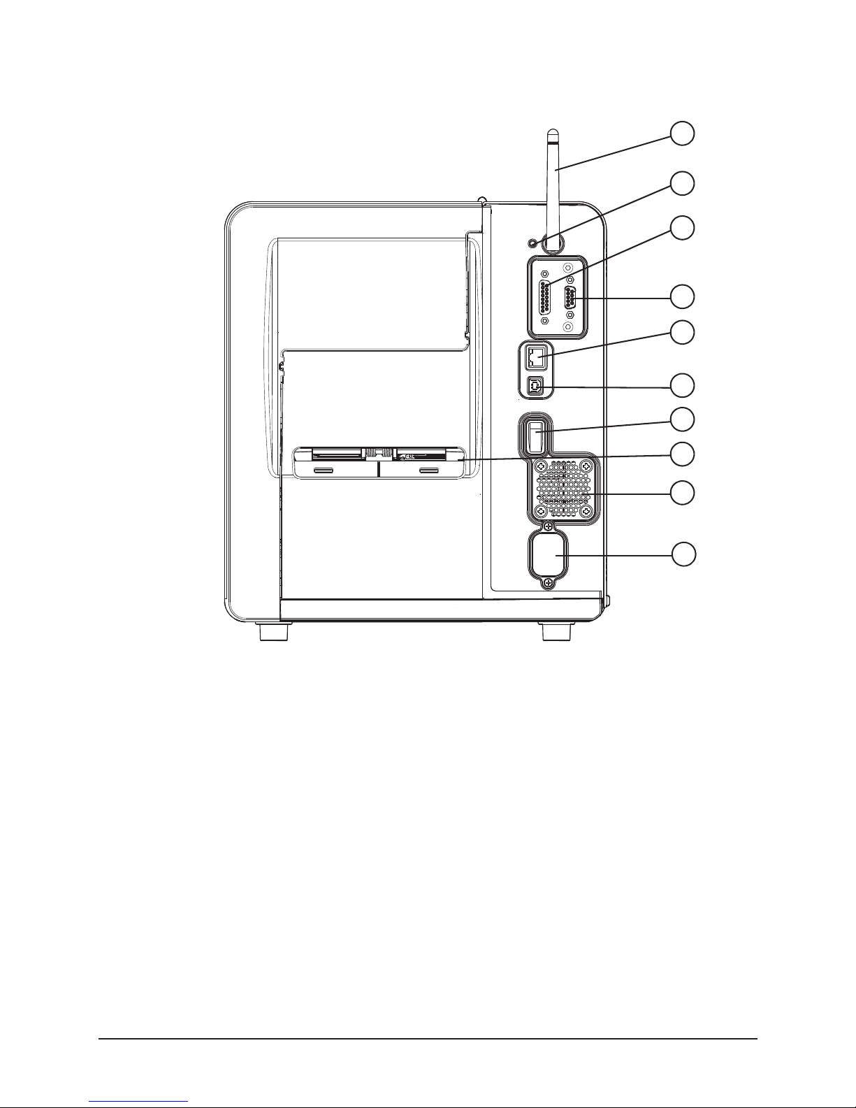
Figure: 2 - 2 Rear View
1
2
3
4
5
6
7
8
1. Wireless Antenna (Optional)
2. Reset Switch
3. GPIO Port (Optional)
4. Serial Port (Optional)
5. Ethernet/Network Port
9
10
6. USB Port
7. Power Switch
8. Fanfold Media Slot
9. Rear Compartment Vent
10.AC Power Inlet
STp.1120n User’s Guide 4
Page 15

Figure: 2 - 3 Media Area
.
1. Power Ribbon Transport Assembly (Optional)
2. Ribbon
3. Media
4. Media Hanger
5. Printhead Carriage Assembly
6. Printhead Latch
7. Printhead Latch Lever
8. Rear Fanfold Media Access Slot
9. Platen Carriage Assembly
10.Media Width Guide Adjustment
Knob
11.Bouncer
12.Lower Fanfold Media Access
Slot
13.Power Media Rewinder
Assembly (Optional)
1
2
3
4
5
6
7
8
9
10
11
12
13
Overview | 2
5 STp.1120n User’s Guide
Page 16

2 | Overview
Standard Features
The thermal printer has the following standard features:
Table 1: Standard Features
Features Descriptions
Max Print Speed 8 IPS / 203 mmps
Resolution 300 dpi / 11.8 dpmm
Memory 32MB Flash (8MB User Space) / 64MB DDR2 SDRAM
Printer Type • Direct Thermal
• Thermal Transfer (Optional)
Media Supply • Fan fold
• Roll-fed
• Die-cut
• Continuous Labels: perforated or continuous tag/ticket stock (8”
[203mm] roll max diameter on 1.0”, 1.5” or 3” [25mm, 38mm or
76mm] core).
Double-sided Top-of-Form
Sensor
Tear Bar Removable bar for tearing off gapped or continuous media.
Media Back Feed Capable of backing up at least 1.0” (for near edge printhead).
Control panel LED backlit color QVGA LCD with touchscreen.
Reset Button Inset on the rear of the unit for recovery or the resetting of the screen
LEDs Two LEDs on the front panel for Power and Error.
Power Switch Positioned on the rear of the unit.
Chassis / Media Cover Diecast construction with a clear side window.
Bar Codes See Appendix A
Fonts See Appendix A
Downloadable Font Types • True-Type Scalable
Adjustable position for center-biased stock:
• Label Gap
•Notch
• Reflective black mark on the bottom or the top of the form
calibration.
• Intellifont Scalable
• PCL Bitmap
Graphics Full support of PCL5e and GL/2 graphics capability.
STp.1120n User’s Guide 6
(Support for various host-based file fomats [PCX, BMP] are not part of
the PCL5e standard but are supported and converted by standard
applications)
Page 17

Features Descriptions
Overview | 2
Industry Standard Printer
Language
Interfaces • USB 2.0 Device
Real Time Clock User replaceable battery
Printer Driver Supported
Operating Systems
Operating Temperature 32°F (0°C) to 104°F (40°C)
Supported Languages in the
Display
HP PJL, HP PCL5e, HP GL/2 and HP XL, printer languages with autolanguage select and extensions for barcode capabilities. Bi-directional
communications capability is also supported.
• LAN 10/100
• Windows XP
• Windows Vista
• Windows 7
Front panel languages are configurable via translation files which may
be loaded on the printer. Check with your distributor for the most recent
list of available translations.
Options
The following options are available:
• Thermal Transfer (Ribbon)
• Internal Power Rewind with Batch Rewind
• Media Present Sensor
• Peel and Present
• Media Cutter
• Media Cutter Tray
• Applicator Port (General Purpose I/O) and Serial Port (RS-232C)
• Wireless Module
•USB Host Port
• Audio Indicator
• Synchronized Media Hanger
• Media Hub with 1.0”,1.5” or 3” Media Hub Adaptors
• Non-US Power Cords
7 STp.1120n User’s Guide
Page 18

2 | Overview
Unpacking the Printer
Upon receiving the printer, verify the box is undamaged. Carefully unpack the printer
from its packaging and visually check for any physical damage that may have occured
during shipment.
Checking the Contents
The contents may vary depending on your configuration. It is recommended that all
packaging materials be saved if the printer is to be shipped again. If the packaging
material is discarded, new packaging material may be available from your reseller.
• Printer
• Power Cord
• Driver CD
• Product documentation not included on the CD
• Accessories/Options
Additional items that may be required include the following:
• All Applicable Communication Cables
•Media
• Ribbon
Specifications
Print Characteristics
Table 2: Print Characteristics
4” Near Edge
Print Resolution 300 dpi (11.8 dpmm)
Max Print Width 4.27” (108.5 mm)
Max Print Speed 8 IPS (203 mmps)
Max Feed Speed 10 IPS (254 mmps)
Max Back-up Speed 5 IPS (127 mmps)
Media Width Range* 1” - 4.65” (25.44 mm - 118.1
mm)
Media Thickness Range* .003” - .010” (.076 mm - .254
Ribbon Width Range** 1” - 4.65” (25.44 mm - 118.1
Print Length .2” - 99” (5.08 mm - 2475.6
STp.1120n User’s Guide 8
mm)
mm)
mm)
Page 19

*Media wound out.
**Coated side in or out.
Dimensions and Weight
Table 3: Dimensions and Specifications
Height Width Depth Weight
11.9 in (30.3 cm) 10.8 in (27.4 cm) 18.7 in (47.5 cm) 41 lbs. (19 kg)
Environmental
Table 4: Temperatures
Temperature Humidity
Operating 5°C to 40°C <=20% to 80%
Storage -20°C to 60°C <=35%
Thermal Shock 0°C to 60°C Ambient
Overview | 2
Print Driver Requirements
Table 5: Print Driver Minimum System Requirements
Minimum System Requirements
Processor / Speed 500 MHz processor
RAM 512MB
Hard Drive Space 6MB
Supported Operating Systems Windows XP - x86 & x64
Windows Vista - x86 & x64
Windows 7 - x86 & x64
Configuration Utility
Table 6: Configuration Utility Minimum System Requirements
Minimum System Requirements
Processor / Speed 500 MHz processor
9 STp.1120n User’s Guide
Page 20

2 | Overview
Minimum System Requirements
Supported Operating Systems Windows XP - x86 & x64
Windows Vista - x86 & x64
Windows 7 - x86 & x64
Windows 2003 Server - x86 & x64
Windows 2008 Server - x86 & x64
Windows 2003 Server R2 - x86 & x64
RAM 256MB
Hard Drive Space 5MB
Minimum Screen Resolution 800 x 600
.NET Framework 2.0
STp.1120n User’s Guide 10
Page 21

3 Connections and Setup
Connections
Power
To connect the printer to a viable power source, please follow the steps below.
Caution: Ensure the printer power switch is off before connecting the AC power and
data/network connectivity cables to the printer.
Caution: Adhere to all environmental requirements when installing and using the printer.
Use of the product in an unsuitable environment may affect print quality and the
durability of the printer and may void the manufacturer’s warranty.
1. Place the printer on a suitable level surface capable of securely supporting 50lbs.
2. Connect the AC power cord to the AC power inlet on the back of the printer.
3. Connect the AC power cord to AC utility power.
Data
Printer data connectivity can be accomplished by the following standard or optional
interfaces:
•USB
• Ethernet/Network
• Serial (Optional)
• GPIO (Optional)
Connect the appropriate interface cables for your network configuration.
Media Loading
The printer is designed to print with the media being center-biased. There are three
different media mounts available including two media hangers and one media hub.
The standard cantilever mount requires the manual center-alignment of the media.The
optional media hanger synchronizes the adjustment to facilitate the centering of the
media. The optional media hub is designed to center-bias the media as well.
Please consult your reseller to obtain the appropriate media.
Note: The printer should be connected to AC power and running during media loading.
11 STp.1120n User’s Guide
Page 22

3 | Connections and Setup
1. Inside media adjustment lever
2. Paper Low Sensor (Optional)
3. Self-centering media hanger
4. Outside media adjustment lever
5. Media adjuster knob
1
2
3
4
5
Media Hanger - Self-Centering
Figure: 3 - 1 Self-Centering Media Hanger
Media core size:
• 3” (76.199mm)
Media roll diameter:
• Maximum -- 8”
Media Roll Width:
STp.1120n User’s Guide 12
Page 23

Connections and Setup | 3
• Maximum -- 4.65”
Media thickness:
• .003” to .01”
Media dimensions:
• Minimum specifications - .5” H x 1” W
Note: Ensure there is no tape or adhesive residue on the media roll.
Installing Media for the First Time
1. Open the media cover.
2. Unlock the printhead mechanism by turning the printhead latch lever clockwise
about 190
Note: Do not unlatch the printhead mechanism.
Figure: 3 - 2 Unlock the Printhead Mechanism
°.
13 STp.1120n User’s Guide
Page 24

3 | Connections and Setup
3. Center the media adjuster knob and pull it to widen the gap between the two media
adjustment levers.
Figure: 3 - 3 Self-Centering Media Hanger from Top
4. Rotate the outside media adjustment lever downward.
Figure: 3 - 4 Outside Media Adjustment Lever
STp.1120n User’s Guide 14
Page 25

Connections and Setup | 3
5. Gently route the media core over the outside media adjustment lever onto the
media hanger.
Caution: Be careful not to damage the outside media adjustment lever.
Figure: 3 - 5 Media Installation
6. Rotate the outside media adjustment lever upward.
Figure: 3 - 6 Outside Media Adjustment Lever
7. Slide the media adjuster knob inward to center the media roll on the media hanger.
15 STp.1120n User’s Guide
Page 26

3 | Connections and Setup
Note: Ensure the media roll turns freely. There should be .8mm to 1.5mm clearance
between the media adjustment levers and the media roll.
8. Rotate the media guide adjustment knob counter clockwise to widen the guides
until they are set slightly wider than the width of the media.
Figure: 3 - 7 Media Guide Adjustment Knob
9. Route the media under the bouncer and into the media guides.
Figure: 3 - 8 Media Guides
Media Guides
STp.1120n User’s Guide 16
Page 27

Connections and Setup | 3
10.Press the pinch roller knob and slide the media .25 inches beyond the pinch roller.
Figure: 3 - 9 Pinch Roller
Pinch Roller Knob
Pinch Roller
11.Rotate the media guide adjustment knob clockwise to tighten the guides.
Note: Ensure the guides are neither too tight nor too loose on the media or print quality
will be affected.
Figure: 3 - 10 Tighten Media Guide Adjustment Knob
17 STp.1120n User’s Guide
Page 28

3 | Connections and Setup
12.Rotate the latch lever counter-clockwise until the printhead mechanism is locked.
Figure: 3 - 11 Lock the Printhead Mechanism
Note: If the media has been installed properly and read by the autoloading sensor, it
should automatically feed under the printhead once the printhead carriage assembly has
been latched and locked. If the media does not automatically load, unlatch the printhead
assembly and manually feed the media under the printhead. Upon locking the printhead,
it would be beneficial to both feed the media by selecting the Feed button on the main
menu to properly set the next label and perform a Paper Calibration.
13.Set the Top-of-Form sensor
Note: Refer to the section called “Setting the Top-of-Form Sensor”.
STp.1120n User’s Guide 18
Page 29

Media Hanger - Cantilever
Figure: 3 - 12 Cantilever Media Hanger
Connections and Setup | 3
1
2
3
1. Inside media adjustment lever
2. Cantilever media hanger
3. Outside media adjustment lever
Media Specifications
Media core size:
• 3” (76.199mm)
Media roll diameter:
• Maximum -- 8”
Media Roll Width:
• Maximum -- 4.65”
Media thickness:
• .003” to .01”
Media dimensions:
19 STp.1120n User’s Guide
Page 30

3 | Connections and Setup
• Minimum specifications - .5” H x 1” W
Note: Ensure there is no tape or adhesive residue on the media roll.
Installing Media for the First Time
1. Open the media cover.
2. Unlock the printhead mechanism by turning the printhead latch lever clockwise
about 190°.
Note: Do not unlatch the printhead mechanism.
Figure: 3 - 13 Unlock the Printhead Mechanism
STp.1120n User’s Guide 20
Page 31

Connections and Setup | 3
3. Rotate the inside media adjustment lever and position the bottom of the lever to the
appropriate width so the media is centered with the printer carriage assembly.
Figure: 3 - 14 Cantilever Media Adjustment
4. Rotate the inside media adjustment lever upward to lock its position.
21 STp.1120n User’s Guide
Page 32

3 | Connections and Setup
5. Rotate the outside media adjustment lever outward.
Figure: 3 - 15 Cantilever Media Adjustment
6. Gently route the media core over the outside media adjustment lever onto the
media hanger.
Caution: Be careful not to damage the outside media adjustment lever.
STp.1120n User’s Guide 22
Page 33

Connections and Setup | 3
7. Slide the outside media adjustment lever inward towards the media core and rotate
the lever upwards to lock in place.
Figure: 3 - 16 Cantilever Media Adjustment
Note: Ensure the media roll turns freely. There should be .8mm to 1.5mm clearance
between the media adjustment levers and the media roll.
23 STp.1120n User’s Guide
Page 34

3 | Connections and Setup
8. Rotate the media guide adjustment knob counter-clockwise to widen the guides
until they are set slightly wider than the width of the media.
Figure: 3 - 17 Media Guide Adjustment Knob
9. Route the media under the bouncer and into the media guides.
Figure: 3 - 18 Cantilever Media Adjustment
Media Guides
STp.1120n User’s Guide 24
Page 35

Connections and Setup | 3
10.Press the pinch roller knob and slide the media .25 inches beyond the pinch roller.
Figure: 3 - 19 Pinch Roller
Pinch Roller Knob
Pinch Roller
11.Rotate the media guide adjustment knob clockwise to tighten the guides.
Note: Ensure the guides are neither too tight nor too loose on the media or print quality
will be affected.
Figure: 3 - 20 Tighten Media Guide Adjustment Knob
25 STp.1120n User’s Guide
Page 36

3 | Connections and Setup
12.Rotate the latch lever counter-clockwise until the printhead mechanism is locked.
Figure: 3 - 21 Lock the Printhead Mechanism
Note: If the media has been installed properly and read by the autoloading sensor, it
should automatically feed under the printhead once the printhead carriage assembly has
been latched and locked. If the media does not automatically load, unlatch the printhead
carriage and manually feed the media under the printhead. Upon locking the printhead, it
would be beneficial to feed the media by selecting the Feed button on the main menu to
properly set the next label.
13.Set the Top-of-Form sensor.
Note: Refer to the section called “Setting the Top-of-Form Sensor”.
STp.1120n User’s Guide 26
Page 37

Media Hub
1
2
3
4
Figure: 3 - 22 Media Hub Layout from Top
5
Connections and Setup | 3
1. Media hub adjustment channels
2. Media hub adjustment lever
3. Hub adjustment slots
4. Media hub
5. Core holders
Media Specifications
Media core size:
• 3” (76.199 mm) standard
• 1” (25.4 mm) optional
• 1.5” (38.099 mm) optional
Media roll diameter:
• Maximum - 8”
Media roll width:
• Maximum - 4.65”
Media thickness:
• .003” to .01”
27 STp.1120n User’s Guide
Page 38

3 | Connections and Setup
Media dimensions:
• Minimum specifications - .5” H x 1” W
Note: Ensure there is no tape or adhesive residue on the media roll.
Installing Media for First Time
1. Open the media cover.
2. Unlock the printhead mechanism by turning the printhead latch lever clockwise
about 190°.
Note: Do not unlatch the printhead mechanism.
Figure: 3 - 23 Unlock the Printhead Mechanism
STp.1120n User’s Guide 28
Page 39

Connections and Setup | 3
3. Press the media hub adjustment lever and pull the media hanger outward using the
handle.
Figure: 3 - 24 Media installation
Media Hub
Adjustment
Lever
Hub
Handle
4. Hold the media hub adjustment lever and place the media core on the core holders.
5. Slide the media hub inward using the handle and release the hub adjustment lever
once the media is supported.
Figure: 3 - 25 Media Installation
29 STp.1120n User’s Guide
Page 40

3 | Connections and Setup
6. Rotate the media guide adjustment knob counter-clockwise to widen the guides
until they are set slightly wider than the width of the media.
Figure: 3 - 26 Media Guide Adjustment Knob
7. Route the media under the bouncer and into the media guides.
Figure: 3 - 27 Media Guide
Bouncer
Media
Media Guide
Guide
STp.1120n User’s Guide 30
Page 41

Connections and Setup | 3
8. Press the pinch roller knob and slide the media .25 inches beyond the pinch roller.
Figure: 3 - 28 Pinch Roller View from Top
Pinch Roller Knob
Pinch Roller
9. While pressing the pinch roller knob, rotate the media guide adjustment wheel until
the media guide touches the media on both sides.
Caution: Ensure the media guides are neither too tight nor too loose or print quality will
be affected and feed issues may develop.
10.Rotate the media guide adjustment knob clockwise to tighten the guides.
31 STp.1120n User’s Guide
Page 42

3 | Connections and Setup
Note: Ensure the guides are neither too tight nor too loose on the media or print quality
will be affected.
Figure: 3 - 29 Tighten Media Guide Adjustment Knob
11.Rotate the latch lever counter-clockwise until the printhead mechanism is locked.
Figure: 3 - 30 Lock the Printhead Mechanism
Note: If the media has been installed properly and read by the autoloading sensor, it
should automatically feed under the printhead once the printhead carriage assembly has
been latched and locked. If the media does not automatically load, unlatch the printhead
carriage and manually feed the media under the printhead. Upon locking the printhead, it
STp.1120n User’s Guide 32
Page 43

Connections and Setup | 3
would be beneficial to feed the media by selecting the Feed button on the main menu to
properly set the next label.
12.Set the Top-of-Form sensor.
Note: Refer to the section called “Setting the Top-of-Form Sensor”.
33 STp.1120n User’s Guide
Page 44

3 | Connections and Setup
Installing Ribbon
For thermal transfer printing, ribbon must be installed. The ribbon should be slightly
wider than the print media being used to ensure proper coverage.
1. Open the media cover.
2. Rotate the printhead latch lever clockwise to unlock and raise the printhead
carriage assembly .
Figure: 3 - 31 Printhead Latch Lever
3. Slide the ribbon core over the ribbon supply hub until the core is centered on the
hub.
STp.1120n User’s Guide 34
Page 45

Note: Only use ribbon with a 1” diameter core.
Figure: 3 - 32 Install Ribbon
Ribbon Supply Hub
Connections and Setup | 3
4. Route the ribbon between the ribbon cam roller and the green top-of-form
adjustment lever .
Note: The printer supports both inside ink and outside ink. Ensure the ink side faces the
media.
Note: See the Menu section for information on setting the printer to run inside or outside
ink.
35 STp.1120n User’s Guide
Page 46

3 | Connections and Setup
Caution: Do not route the ribbon under the green top-of-form sensor.
Figure: 3 - 33 Route Ribbon (Inside ink ribbon is shown)
Cam Roller
Inside Ink Shown
Top-of-Form
Sensor Adjustment
Lever
STp.1120n User’s Guide 36
Page 47

Connections and Setup | 3
5. Route the ribbon under the printhead, over the ribbon shield and clockwise around
the ribbon rewinder hub.
Figure: 3 - 34 Route to Ribbon Rewinder Hub
Note: Roll the ribbon around the ribbon rewinder hub at least five (5) times to ensure it
will stay in position.
6. Ensure the thermal transfer option is selected through the control panel.
7. Set the thermal transfer option to coated in (inside ink) or coated out (outside ink)
depending on the ribbon type.
Note: See the menu section for more information about the printer settings.
37 STp.1120n User’s Guide
Page 48

3 | Connections and Setup
8. Rotate the printhead carriage assembly counter-clockwise until it latches.
Figure: 3 - 35 Latch the Printhead Carriage Assembly
9. Rotate the printhead latch lever counter-clockwise to lock the printhead carriage.
Note: Ensure the printhead latch lever has locked the printhead mechanism before
printing or the printer will enter a no-print condition.
Note: When removing the ribbon from the ribbon rewinder hub, grasp the center of the
ribbon, squeeze to compress it and pull outward away from the rewinder hub.
STp.1120n User’s Guide 38
Page 49

Connections and Setup | 3
Configuring Media and Ribbon Settings
Once the media and ribbon have been loaded, the print parameters should be set to
match the type of media and ribbon being used. This will ensure optimal print quality.
Once set, the parameters will not need to be set again unless the media or ribbon types
are changed.
Using Media and Ribbon IDs
Media and ribbons supplied by Source Technologies and other vendors may have a 4digit media ID and ribbon ID assigned. These codes may be entered from the printer
front panel. All relevant print parameters will be automatically configured.
1. Select Menu > Basic > Media > Enter ID.
2. Select the Enter Paper ID field and enter the appropriate 4-digit code.
3. Select the green Accept button to confirm your selection.
4. Select the Enter Ribbon ID field and enter the appropriate 4-digit code.
5. Select the green Accept button to confirm your selection.
6. After selecting the Home button, select the green Accept button to again confirm
your selection or the red Reject button to cancel the changes.
Note: Although using media and ribbon IDs usually produce very good results, minor
adjustments may be required. Refer to the section titled Adjusting Media and Ribbon
Settings.
Selecting Media and Ribbon Types Manually
If media and ribbon IDs are not known, the media and ribbon types may be selected
manually.
1. Select Menu > Basic > Media > Select Type.
2. Using the up and down arrows, select your paper type.
Note: If the paper type is not known, either select Coated Direct Thermal for direct
thermal printing or select Coated Thermal Transfer for printing with a ribbon.
3. Tab to the Ribbon screen.
4. Using the up and down arrow, select your ribbon type.
Note: If the ribbon type is not known, select Wax to start. This selection can always be
changed if required.
5. Tab to the Settings screen.
39 STp.1120n User’s Guide
Page 50

3 | Connections and Setup
6. Select the Paper Sensor Type button until your paper type appears. The options
are as follows:
•Gap
• Mark on Top
• Mark on Bottom
•Notch
• Continuous
Note: For more information, refer to the section Setting the Top-of-Form Sensor.
7. Select the Paper Sensor Side button until the correct option appears. The options
are as follows:
•Outside
• Inside
Note: For more information, refer to the section Setting the Top-of-Form Sensor.
8. Select the Ribbon Mode button until the correct option appears. The options are as
follows:
•None
• Coated In
• Coated Out
Note: For more information, refer to the section Setting the Top-of-Form Sensor.
Note: CSI ribbon (shiny side facing outward) should be installed where the ribbon
unwinds in a counter-clockwise direction. CSO ribbon (dull side facing outward) should
be installed where the ribbon unwinds in a clockwise direction. If these settings do not
match the ribbon type being used, the ribbon supply hub will turn in the wrong direction.
Setting the Media and Ribbon Parameters Manually (Advanced)
There are times when all print parameters must be set manually. This can happen when
a new or specialized media or ribbon are being used. This advanced procedure will use
the Custom Manual utility.
Note: Some values may be grayed-out, meaning they are automatically set by default.
To change these values, select the Auto button next to the value field and then select the
green Accept button to confirm your choice to change to manual mode.
Note: Please see the Menu section for more information.
1. Select Menu > Advanced > Media.
2. Select the Paper Sensor Type field until the correct paper type appears. The
options are as follows:
STp.1120n User’s Guide 40
Page 51

Connections and Setup | 3
•Gap
• Mark on Top
• Mark on Bottom
•Notch
• Continuous
3. Select the Paper Sensor Side field until the correct option appears. The options
are as follows:
•Outside
• Inside
4. Select the Ribbon Mode field until the correct option appears. The options are as
follows:
•None
• Coated In
• Coated Out
5. Tab to the next screen and enter values for Heat and Heat Balance.
6. Tab to the next screen and enter values for Head Pressure and Rewinder
Tension.
7. Tab to the next screen and enter values for Ribbon Tension Front and Ribbon
Tension Rear.
8. Tab to the next screen and enter a value for Ribbon Low Diameter.
9. Select the Home button and select the green Accept button to confirm the settings.
41 STp.1120n User’s Guide
Page 52

3 | Connections and Setup
Optional Rewinder
The rewinder is designed to rewind in either direction but the direction must be set
through the menu.
Note: Either the peel plate or the rewinder plate must be installed.
Installation of Media
1. Route the media through the platen carriage assembly.
Note: Follow the instructions for the installed media hanger.
2. Route the media under the platen carriage and around the rewinder shaft.
3. Remove the metal clasp and wind the media around the rewinder shaft in the
desired direction.
Figure: 3 - 36 Rewinder
Clockwise
Metal Clasp
Counter Clockwise
4. Insert the edge of the media into one of the two grooves on the rewinder shaft.
STp.1120n User’s Guide 42
Page 53

Connections and Setup | 3
Note: For thicker labels, remove the label from the backing and insert the backing into
the groove.
Figure: 3 - 37 Media Rewinder
5. Reinstall the metal clasp into the grooves.
Perform the following steps to set the rewinder direction:
1. Select Menu > Basic > Printer Mode.
2. Select one of the three options.
Note: Upon exiting the utility, a prompt will ask the user to accept the changes or reject
them.
Top-of-Form Sensor
This printer is designed to use several types of media. The top-of-form sensor can read
media characteristics from the center to the left inside edge (viewing from the front of the
printer). Setting the top-of-form sensor to read specific media characteristics is done in
the control panel.
43 STp.1120n User’s Guide
Page 54

3 | Connections and Setup
Media Types Supported
There are five paper types that are supported. These include gap, mark on top, mark on
bottom, notch and continuous.
The following are illustrations of the types of supported media but not every supported
media is illustrated. Please contact your reseller for assistance in selecting the
appropriate media for the printer.
Figure: 3 - 38 Gap Example
Figure: 3 - 39 Notch Example
STp.1120n User’s Guide 44
Page 55

Figure: 3 - 40 Mark on Top Example
Figure: 3 - 41 Mark on Bottom Example
Connections and Setup | 3
Figure: 3 - 42 None
45 STp.1120n User’s Guide
Page 56

3 | Connections and Setup
Mark
Inside Sensor Pod
Outside Sensor Pod
Lever
Top-of-Form
Adjustment
Setting the Top of Form Sensor
The top of form sensor enables the printer to determine where the print should begin and
end. Once the appropriate media has been loaded, the media type can be entered
manually into the control panel.
1. Select Menu > Basic > Media from the control panel.
2. Select Select Type.
3. Select the paper and ribbon type.
4. Select Paper Sensor Type.
5. Select the paper sensor side, either inside or outside, that correlates with the type of
media being used.
Note: For example, media types with marks in the middle of the media, select Outside.
Note: The LED of the selected sensor will illuminate.
6. Unlock and release the printhead carriage assembly allowing it to open.
7. Using the adjustment lever, slide the top-of-form sensor so the appropriate LED-lit
sensor pod is centered over the mark, notch or gap that was selected.
Figure: 3 - 43 Example of Top-of-Form Sensor Adjustment on “Mark on Top” media
STp.1120n User’s Guide 46
Page 57

Connections and Setup | 3
Note: For illustration purposes, the image of the printhead carriage assembly was
removed in the image above. The LED sensor pods can be viewed from the front of the
printer, under the printhead carriage assembly. The active sensor pod is lit by an LED.
Note: If the wrong pod is active for your media type, check your settings.
8. Close and lock the printhead carriage assembly.
47 STp.1120n User’s Guide
Page 58

3 | Connections and Setup
Removing Ribbon Wrinkle
1. Center the supply ribbon core so the ribbon overlaps the media equally on both
sides.
2. Verify there are no folds or creases in the ribbon.
3. Adjust the front ribbon shield to the middle position of the mounting slot.
Figure: 3 - 44 Ribbon Shield
Front Ribbon Shield
4. Set the printer to print ten (10) consecutive Quality Labels from the Test menu.
5. Print the labels.
6. Check for ripples drifting left or right in the ribbon between the ribbon supply and the
cam roller.
STp.1120n User’s Guide 48
Page 59

Connections and Setup | 3
Note: If the ripples are vertically straight, advance to step 12 to adjust the ribbon plate.
Figure: 3 - 45 Supply Side Inspection
7. If excessive ripples exist, loosen the 3mm cam roller hex head screw enough to
allow the cam roller to spin.
Figure: 3 - 46 Cam Roller
Cam Roller
Screw
Cam Roller
Adjuster
8. Turn the cam roller adjuster until the ripples are either gone or are vertical.
49 STp.1120n User’s Guide
Page 60

3 | Connections and Setup
Note: The ripples must never drift left or right.
9. Tighten the cam roller screw.
10.Print ten (10) Quality Labels from the test menu.
Note: If wrinkles still appear continue with the adjustment procedure.
11.Loosen the ribbon shield adjustment screws.
12.While printing test labels, slowly adjust the lower shield until the ribbon tension is
constant from left to right and the wrinkles disappear.
Note: Adjust the ribbon shield by adding tension to the side with wrinkling or light print.
Note: Adjustment should eliminate side-to-side wrinkles.
STp.1120n User’s Guide 50
Page 61

Connections and Setup | 3
Installing Cutter and Tray
Warning: To prevent serious injury, never place a finger or object other than media near
the cutter mechanism.
Caution: Never cut paper or media in an area where adhesives exist. Doing so will
damage the cutter and void the manufacturer’s warranty.
Caution: The media cover will not close with both the cutter and present sensor installed
at the same time.
Caution: The printer must be powered off and disconnected from AC utility power prior
to the cutter installation.
The cutter and cutting tray are available options that must be installed after receiving the
printer.
Cutter
Perform the following procedure to install the cutter.
Note: The printer and the cutter tray must be on the same level surface.
1. Remove the lower cover from the printer.
Figure: 3 - 47 Lower Cover
51 STp.1120n User’s Guide
Page 62

3 | Connections and Setup
2. Loosen and remove the media plate thumbscrew and the media plate.
Figure: 3 - 48 Remove Media Plate
Note: Retain the thumbscrew for cutter installation.
3. Align the cutter with the power/data connector and install the thumbscrew to secure
it to the platen carriage assembly.
Figure: 3 - 49 Cutter Installation
STp.1120n User’s Guide 52
Page 63

Connections and Setup | 3
4. Rotate the cutter until it magnetically locks into place.
5. Activate the cutter option in the Options menu by selecting Menu > Advanced >
Printer > Options > Cutter.
Note: Feed a label through the printer and observe the cut distance to ensure it cuts on
the gap. If it cuts on the label, adjust your Cut Distance Adjust settings in the
Adjustments menu.
Note: A negative value moves the cut line toward the current label being printed. A
positive value moves the cut line toward the next label to be printed.
Cutter Tray
The cutter tray collects labels and media after they have been cut. The tray may be
installed before or after the installation of the cutter.
1. Place the tray mounting hooks into the baseplate slots.
Note: For a clearer illustration, the cutter has been removed from the illustration below.
Figure: 3 - 50 Cutter Tray Installation
Mounting Hooks
Baseplate
Slots
53 STp.1120n User’s Guide
Page 64

3 | Connections and Setup
Print Driver Installation
Overview
This section is intended to instruct the user about the installation of the Performance
Series Print Driver Setup Utility on a Windows® -based computer. The Setup Utility is
installed and used to successfully install the print driver for USB or network-connected
printers.
This installation should be executed only on a computer where no printer driver or print
driver utility has been installed unless otherwise noted.
The installer should note the following:
• The printer driver files are inst alled into the Windows print system so when a USB
printer is connected or a network printer is added, the system will automatically
recognize the printer and install the driver for it.
• The print driver utility is inst alled as a Windows program on the computer. The utility is a Windows program that can be accessed at any time to add additional Performance Series printers.
Requirements
The Performance Series print driver setup is supported on the following 32-bit or 64-bit
operating systems:
• Windows XP
• Windows V i sta
• Windows 7
• Windows Server 2003
• Windows Server 2008
• Windows Server 2008 R2
STp.1120n User’s Guide 54
Page 65

Connections and Setup | 3
Installation Instructions
Downloading the Performance Series Print Driver From the Website
Note: The installation file is also accessible from the product CD that shipped with the
printer.
1. Enter the following URL into the Web browser:
http://www.sourcetech.com/support/drivers-downloads/drivers
2. Select Midrange Thermal Printers.
3. Select STpSeriesPrintDrive Setup (x86 & x64).
Note: The File Download window is displayed.
Figure: 3 - 51 File Download Window
4. Select Save and browse to the appropriate location where the file can be saved.
Note: For future reference, be sure to note the directory where the file has been saved.
5. Select Save from the Save As window.
6. Select Close from the Download Complete window.
Accessing the Performance Series Print Driver from the Product CD
1. Load the product CD in the computer CD/DVD drive.
Note: The main installation screen should be displayed. If not, select Start > My
Computer > Device w/Removable Storage. Then select the drive letter that
corresponds with your CD/DVD drive.
55 STp.1120n User’s Guide
Page 66

3 | Connections and Setup
2. Select Software.
Figure: 3 - 52 Installation Utility - Software
3. Select Windows Print Driver and proceed with the installation instructions.
Figure: 3 - 53 Installation Utility - Windows Print Driver
STp.1120n User’s Guide 56
Page 67

Connections and Setup | 3
Installing the Print Driver for a USB Connected Printer
Caution: If your printer is not connected via USB, do not execute this step. Instead, refer
to the installation instructions for connecting locally or to a network.
Caution: Do not connect a USB cable to the printer at this point.
1. Locate the Performance Series Print Driver setup file from the saved location or
from the product CD launch.
2. Double-click STpSeriesPrintDriverSetup.msi.
Note: This step is not required if continuing from the product CD launch.
3. Select Next from the “Performance Series Print Driver Setup Wizard” window.
Figure: 3 - 54 Performance Series Print Driver Setup Wizard
57 STp.1120n User’s Guide
Page 68

3 | Connections and Setup
4. Select Install Driver Files Only and then select Next.
Figure: 3 - 55 Performance Series Install Files/Add Printer Selection
5. Browse to the appropriate folder location, select the user option and then select
Next.
Figure: 3 - 56 Installation Folder
STp.1120n User’s Guide 58
Page 69

6. Select Next.
Figure: 3 - 57 Confirm Installation
Connections and Setup | 3
Note: The “Installing Source Technologies Performance Series Print Driver” progress
window will display.
Figure: 3 - 58 Print Driver Installation Progress Window
59 STp.1120n User’s Guide
Page 70

3 | Connections and Setup
7. Select Close.
Figure: 3 - 59 Installation Complete
Note: The following window may appear after selecting close. Select Continue
Anyway.
Figure: 3 - 60 Hardware Installation Warning Window
Note: The appearance of this window may be different from the illustration depending on
your operating system.
STp.1120n User’s Guide 60
Page 71

Connections and Setup | 3
Note: The “Copying Files” dialog box will display while the driver files are copied to the
system. When the dialog box closes, the installation is complete.
Figure: 3 - 61 Copying Files Dialog Box
8. Confirm the Performance Series printer is powered on.
9. Connect a USB cable from the computer to the USB port on the Performance
Series printer.
Note: If using Windows XP, continue the installation using the Found New Hardware
Wizard. If using another operating system, your installation is complete.
10.Select No, not this time and then select Next.
Figure: 3 - 62 Found New Hardware Wizard Welcome Window
61 STp.1120n User’s Guide
Page 72

3 | Connections and Setup
11. Select Install the software automatically (Recommended) and then select Next.
Figure: 3 - 63 Found New Hardware - Install the Software
Note: The wizard progress window will display while the printer driver files are located.
Figure: 3 - 64 Found New Hardware Wizard Progress Window
STp.1120n User’s Guide 62
Page 73

Connections and Setup | 3
Note: The following window may appear. Select Continue Anyway.
Figure: 3 - 65 Hardware Installation Window
The following steps are not always seen on all Windows® XP systems.
12.Select OK.
Figure: 3 - 66 Insert Disk Window
13.Browse to C:\Source Technologies LLC\STpSeriesDriver.
Figure: 3 - 67 Files Needed Window
14.Select the appropriate file with one of the following extensions and then select
Open:
•.ini
•.dll
63 STp.1120n User’s Guide
Page 74

3 | Connections and Setup
•.gpd
Figure: 3 - 68 Locate File Window
15.Select OK.
Figure: 3 - 69 Files Needed Window
STp.1120n User’s Guide 64
Page 75

16.Select Finish.
Figure: 3 - 70 Completing the Found New Hardware WIzard Window
Connections and Setup | 3
The printer has been installed and is available to Windows applications.
65 STp.1120n User’s Guide
Page 76

3 | Connections and Setup
Installing the Print Driver for a Network-Connected Printer
Caution: If your printer in not a network-connected printer, do not execute this step.
Instead, refer to the installation instructions for installing the print driver for a
USB connected printer.”
1. Locate the Performance Series Print Driver Setup file from the saved location or the
product CD launch.
2. Double-click STpSeriesDriverSetup.msi.
Note: This step is not required if continuing from the product CD launch.
3. Select Next from the “Performance Series Print Driver Setup Wizard” window.
Figure: 3 - 71 Performance Series Print Driver Setup Wizard
STp.1120n User’s Guide 66
Page 77

4. Select Install Driver Files and Add Printer.
Figure: 3 - 72 Install Files/Add Printer WIndow
Connections and Setup | 3
5. Select Next.
Figure: 3 - 73 Confirm Installation
67 STp.1120n User’s Guide
Page 78

3 | Connections and Setup
Note: The wizard progress window will display while the printer driver files are located.
Figure: 3 - 74 Print Driver Installation Progress Window
6. Select Close.
Figure: 3 - 75 Installation Complete
Note: The “Welcome to the Add Printer Wizard” will display.
STp.1120n User’s Guide 68
Page 79

Connections and Setup | 3
7. Select Next.
Figure: 3 - 76 Add Printer Wizard Welcome Window
Note: The “Install Printer Software” screen will display with a list of supported
Performance Series printers.
8. Select the Performance Series printer model of the printer being installed and then
select Next.
Figure: 3 - 77 Install Printer Software
69 STp.1120n User’s Guide
Page 80

3 | Connections and Setup
9. Select Finish to complete the installation.
Figure: 3 - 78 Completing the Add Printer WIzard
Note: The “Hardware Installation” window will display although the screen may appear
differently depending on the operating system.
10.Select Continue Anyway.
Figure: 3 - 79 Hardware Installation
Note: The “Copying Files” dialog box will display while the driver files are being copied to
the system. The dialog box will close once the installation is complete.
Figure: 3 - 80 Copying Files
STp.1120n User’s Guide 70
Page 81

Connections and Setup | 3
Note: The screenshot may appear different from the illustration depending on the
operating system being used.
Once the installation is complete, the printer is available to Windows applications.
71 STp.1120n User’s Guide
Page 82

3 | Connections and Setup
Add Printer - USB Connected Printer
Caution: This procedure should only be followed if the Performance Series Print Driver
Utility has already been installed.
1. Confirm that the Performance Series printer is powered on.
2. Connect the USB cable from the computer to the USB port on the Performance
Series printer.
Note: For operating systems other than Windows XP, the print driver installation and the
printer installation are complete.
Perform the following steps only if using the Windows XP operating system.
3. Select No, not this time and then select Next.
Figure: 3 - 81 Found New Hardware Wizard
STp.1120n User’s Guide 72
Page 83

Connections and Setup | 3
4. Select Install the software automatically (Recommended), then select Next.
Figure: 3 - 82 Found New Hardware - Install the Software
Note: The wizard progress window will display while the printer driver files are located.
Figure: 3 - 83 Wizard Progress Window
73 STp.1120n User’s Guide
Page 84

3 | Connections and Setup
Note: The following window may appear. Select Continue Anyway.
Figure: 3 - 84 Hardware Installation Window
The following steps are not always seen on all WIndows XP systems.
5. Select OK.
Figure: 3 - 85 Insert Disk Window
6. Browse to C:\Source Technologies LLC\STpSeriesDriver.
Figure: 3 - 86 Files Needed Window
STp.1120n User’s Guide 74
Page 85

Connections and Setup | 3
7. Select the appropriate file with one of the following extensions and then select
Open:
•.ini
•.dll
•.gpd
Figure: 3 - 87 Locate File Window
8. Select OK.
Figure: 3 - 88 Files Needed Window
75 STp.1120n User’s Guide
Page 86

3 | Connections and Setup
9. Select Finish.
Figure: 3 - 89 Completing the Found New Hardware Wizard Window
The printer has been installed and is available to WIndows applications.
STp.1120n User’s Guide 76
Page 87

Connections and Setup | 3
Add Printer - Network-Connected Printer
Caution: This procedure should only be followed if the Performance Series Print Driver
Utility has already been installed.
1. Select Start > All Programs > Source Technologies LLC > STp Series Printer
Driver > Add Printer.
Note: The “Add Printer Wizard” will display.
Figure: 3 - 90 Add Printer Wizard
2. Select Next.
Note: The “Install Printer Software” screen will display with a list of supported
Performance Series printers.
77 STp.1120n User’s Guide
Page 88

3 | Connections and Setup
3. Select the Performance Series printer model for the printer being installed and then
select Next.
Figure: 3 - 91 Install Printer Software
Note: If at any time this screen does not display a pre-populated list of supported
Performance Series printers, select Have Disk or browse to the print driver software.
The default location is C:\Source Technologies LLC\STpSeriesDriver.
4. Select Finish to complete the installation.
Figure: 3 - 92 Completing the Add Printer WIzard
Note: The “Hardware Installation” window will display although the screen may appear
differently depending on the operating system.
STp.1120n User’s Guide 78
Page 89

Connections and Setup | 3
5. Select Continue Anyway.
Figure: 3 - 93 Hardware Installation
Note: The “Copying Files” dialog box will display while the driver files are being copied to
the system. The dialog box will close once the installation is complete.
Figure: 3 - 94 Copying Files
Note: The screenshot may appear different from the illustration depending on the
operating system being used.
Once the installation is complete, the printer is available to Windows applications.
79 STp.1120n User’s Guide
Page 90

3 | Connections and Setup
Printer Properties
The properties panel allows the user to set the printer properties via a tabbed interface.
Select the appropriate tab to change settings.
Properties - Print File
The Print File tab allows users to print files with the following extensions:
•.txt
•.pcl
•.pjl
Figure: 3 - 95 Print File Tab
Two actions can be selected:
Table 1: Firmware Update Actions
Name Description
Select File Allows the user to browse and select the appropriate file to be
Send File to Printer Once a file has been selected, the button is enabled and used
STp.1120n User’s Guide 80
sent to the printer.
to send the selected file to the printer.
Page 91

Connections and Setup | 3
Properties - About
The about tab in the properties panel displays driver information for the users to
reference when needed. This information contains the file names and their versions.
Figure: 3 - 96 Properties - About
Your version number may vary from this example.
81 STp.1120n User’s Guide
Page 92

3 | Connections and Setup
Printing Preferences
Printing Preferences - Media Settings
The Media Settings tab allows the user to manage the printer’s media settings. These
include the following:
Table 2: Properties - Media Settings
Name Description
Units of Measure Allows the user to set the units of measure to Imperial or Metric.
Orientation Allows the user to set the orientation of the print job.
Number of Copies Allows the user to set the number of copies for the specified
print job.
Media Size The user may select a predefined media size or click on the
Custom button and create a custom media size.
Settings Allows the user to save the configuration of the print driver
settings.
Figure: 3 - 97 Media Settings
STp.1120n User’s Guide 82
Page 93

Figure: 3 - 98 Media Size
Connections and Setup | 3
Printing Preferences - Print Settings
The following print settings may be adjusted:
Table 3: Print Settings
Name Description
Print Speed The speed at which the printer will print the labels.
Slew Speed* The rate of paper movement between printing areas when
using the GPIO applicator.
Feed Speed The rate of label movement during feed.
Reverse Speed The rate of the label movement during backup positioning.
Print Darkness Allows for the adjustment of the darkness of the printed image
due to printhead thermal variations.
Horizontal Offset Shifts the horizontal start of the print position on the labels.
Vertical Offset Shifts the vertical start of the print position on the labels.
Settings Allows the configuration settings to be saved.
* Future
83 STp.1120n User’s Guide
Page 94

3 | Connections and Setup
Figure: 3 - 99 Print Settings
Whenever a speed setting has been changed, the following warning may appear:
Figure: 3 - 100Speed Warning
STp.1120n User’s Guide 84
Page 95

Connections and Setup | 3
Printer Preferences > Custom Commands
Job commands may be set.
Table 4: Custom Commands
Name Description
Start of Job w/FF Sends the FF command at the beginning of the job.
End of Job w/FF Sends the FF command at the end of the job.
Figure: 3 - 101Custom Commands
85 STp.1120n User’s Guide
Page 96

3 | Connections and Setup
STp.1120n User’s Guide 86
Page 97

4 Menu System
Menu Overview
The printer is designed with a touchscreen display. Functions can be enabled and
disabled and settings can be changed through the on-screen menu. Press the buttons on
the screen with the light touch of a finger.
Caution: Do not touch the screen with excessive force or by using sharp objects. Doing
so will damage the touchscreen and may void the manufacturer’s warranty.
Layout of the Display
Navigation
The menu screens have buttons for advancing or returning to screens.
Back Button
The Back button provides the user with the option to return to a previous menu
screen.
Home Button
Selecting the Home button sends the user to the main screen.
Tabbed Browsing
Blue left and right arrow buttons are provided at the bottom right of the screen to
navigate tabbed menus. Select the right arrow to advance to the next tab or the left
arrow to return to the previous tab.
Scrolling
Some menu screens allow for scrolling. Select the appropriate up or down arrow.
Changing V alues
Numeric values can be entered or changed by selecting the field and entering the
values using the numeric keypad. They can also be increased or decreased using
the subsequent plus or minus buttons.
Other menu options are changed by pressing the button until the appropriate
selection appears.
87 STp.1120n User’s Guide
Page 98

4 | Menu System
Ready
Printer
Status
Buttons
Date / Time
Operator Action
Fault Information
Area
Area
Model ID
Connected Devices
and
Mode Indicators
Home Screen
The home screen presents several options to the user.
Thu July 21 11:58:33 2012
Menu Feed Info
Printer Status
The printer status area displays the state of the printer. These states include the
following:
Operator Action Area
Information about the current printer action will be displayed in this area. For example,
“Printing 1 of 3” might be displayed when printing the first of three labels for a print job.
Date / Time
The time and date may be toggled on by pressing the upper right corner of the display.
After pressing the blank area, the current date and time will be displayed on the screen.
Once the home button is pressed, a screen will appear asking the user if the date and
time will be displayed. Select the green Accept button to display the time or the red
Reject button to cancel.
• Ready - The printer is idle and ready to accept internal or external commands.
• Busy - Appears when printing or feeding paper.
• Fault - The printer is busy processing or executing a command. The screen will
become yellow for a warning condition and red for a fault condition.
• Cooling Down - The printer has paused while it is cooling down.
• Waiting - The printer is blocked by the optional Applicator or Present Sensor.
STp.1120n User’s Guide 88
Page 99

Menu System | 4
Fault Information Area
Warnings and faults will be displayed in this area. Once the fault has been corrected, the
message will disappear .
Connected Devices
The symbol for devices connected to the USB host will be presented in this area.
Mode Indicators
The printer will display modes that have been activated. If options have been installed
but not enabled, they will not appear in this area of the display.
Information Button
By selecting the information button from the task bar, the following information can be
accessed.
• System Info
• Settings Report
• Network Report
• Extended Status
• Serial Report
• Applicator Report
• Fonts Report
System Information
The following will be displayed upon selection of the System Info button:
• Printer Model
• Printhead Model
• Sof tware Version
• Firmware Version
• Ribbon Version
•Boot Version
•Board ID
•RAM Size
• Flash Size
• Security Key
• Printer Odometer
89 STp.1120n User’s Guide
Page 100

4 | Menu System
• Printhead Odometer
• Paper Type
• Ribbon Type
• Detected Options
Note: Selecting the down or up arrow will display additional information.
Settings Report
The settings report provides information on the printer settings.
Media Settings
• Paper Sensor Type
• Paper Sensor Side
• Ribbon Mode
•Heat
• Heat Balance
• Head Pressure
• Rewinder Tension
• Ribbon Tension Front
• Ribbon Tension Rear
• Ribbon Low Diameter
Printer Settings
• Cutter Mode
• Rewinder Mode
• Present Sensor Enable
• Print Speed
• Feed Speed
• Reverse Speed
• Present Dist ance
• Error Sound
• Warning Sound
• Disable Paper Low Warning
• Disable Paper Out Warning
• Disable Cover Open Warning
STp.1120n User’s Guide 90
 Loading...