

Page 1

ST9335
Secure MICR Printer
User ’s Guide
2910 Whitehall Park Drive
techsupport@sourcetech.com
Source T echnologies
Charlotte, NC 28273
www.sourcetech.com
800-922-8501
Page 2

This manual serves as a reference for Source T echnologies Secure MICR Printers. The user
manual that ships with your printer contains details on printer setup and operations and should
be read first. This manual should be used as a reference for learning more about MICR
technology , and developing MICR printing applications. This guide was produced to assist IS
T echnicians and Engineers in the use Source T echnologies’ programmed printers with their
custom MICR applications. The guide also contains information on MICR related error
messages that post to the operator panel.
Every effort has been made to ensure that all the information contained in this booklet is
complete and accurate. Changes, typos, and technical inaccuracies will be corrected in
subsequent publications. This publication is subject to change without notice. The
information and descriptions contained in this manual cannot be copied, disseminated, or
distributed without the express written consent of Source Technologies, Inc. No liability,
expressed or implied, will be assumed by Source Technologies, Inc. or its dealers or
affiliates for any damage resulting from use of this information. Additional copies of this
publication can be received through the Marketing Department of Source Technologies.
All other trade names or products used in this manual are for identification purposes only and
may be trademarks or registered trademarks of their respective companies.
Source T echnologies
©
All rights reserved.
Written and produced by Source T echnologies
July 2000 (Updated July 2003)
Page 3

Table of Contents
1 Printer Installation .......................................................... 1
2 MICR Overview................................................................ 2
The Check Processing System .................................... 2
MICR Printing Today.................................................... 2
3 MICR Check Design........................................................ 4
General Features of Check Design ...............................4
Position and Dimension Gauge.....................................4
Design Elements in Detail ............................................ 4
Figure 3.1 Sample Check .............................................9
4 Quality Issues.................................................................. 10
Printer Features ............................................................ 10
MICR T oner ................................................................... 10
MICR Check Stock........................................................ 11
5 Security Issues................................................................13
Check Stock Security Features ..................................... 13
Security Note ................................................................14
6 MICR Features................................................................. 16
MICR Mode................................................................... 16
MICR Fonts................................................................... 16
Secure Fonts ................................................................16
MicroPrint .....................................................................16
Bi-Directional Feedback ............................................... 17
Resource Storage.........................................................17
MICR Menu ...................................................................18
Entering MICR Mode....................................................18
MICR Mode Commands................................................ 20
DES and AES Decryption............................................. 24
MFP Copy Defeat Commands...................................... 25
Custom Character Conversion Commands ...................26
Special Alert and Custom Beep Command ................... 27
7 IBM Host Programming Features and Examples ......... 28
Hex Transfer..................................................................28
Figure 7.1: MICR Mode Command Example ................. 30
Figure 7.2: Sample Check ............................................31
Escape Character Translation....................................... 33
Secure MICR Printer User’s Guide © Source Technologies
July 2003 All rights reserved
Page 4

8 Audit Trail Report ............................................................ 34
Report Details............................................................... 34
Audit Trail Menu ............................................................ 34
Audit Trail Command Set .............................................. 36
Figure 8.1: Audit Trail Command Example ....................40
Figure 8.2: Audit Trail Check Sample ............................41
Figure 8.3 Audit Trail Report..........................................44
9 Error Messages ............................................................... 45
MICR Error Messages .................................................. 46
Appendix A: E-13B MICR Font Mapping ................................. A1
Appendix B: CMC7 MICR Font Mapping................................A2
Appendix C: Secure Numeric Font Mapping .......................... A3
Appendix D: ICR Secure Numeric Font Mapping................... A5
Appendix E: MICR Mode Command Summary...................... A 6
Appendix F: Audit Report Command Summary .......................A7
Appendix G: PJL Based MICR Commands .............................A8
Secure MICR Printer User’s Guide © Source Technologies
July 2003 All rights reserved
Page 5

Section 1: Printer Installation
1 Printer Installation
For complete information on how to unpack and setup your printer, see your printer’s user’s
guide. Please read the following if you are going to install the printer driver shipped with your
printer.
1. Locate the CD that was shipped with your printer.
Note: If you do not have a CD-ROM drive on the host PC, locate another computer with
a CD-ROM drive, start the CD-ROM utility , and then follow the instructions on the screen
to create printer driver diskettes.
2. Follow the instructions in the CD booklet to start the printer setup utility appropriate
for your operating system, i.e. Windows 95, NT , etc. The setup utility will install
printer driver and utilities to manage Source Technologies printer(s) attached to your
PC or Network.
3. The Source Technologies, in most cases, assumes the printer driver
is set to the internal DEFAUL T values. The following Default values should not be
changed for best overall printer performance and data stream requirements of the
ST Secure MICR printer .
- Print Resolution under the Graphic T ab should be set to the Default value of 600
DPI.
- Form Source under the Paper T ab should be set to Default value of By Source.
- Print Quality and PictureGrade under the Graphic T ab should be set to the
Default values of Use Printer Default.
The ST Secure MICR Printer requires a PCL5 or PCL5e data stream. Current level
printer drivers require Graphic Mode under the Graphic Tab be set to either Raster
or GL/2. We recommend Raster . This is the only required non-Default value that
needs to be set in the printer driver.
A majority of other driver options can be set for your particular requirements. The most
obvious of these would be a Paper Tray selection if your application uses the Print Driver
Setting.
Secure MICR Printer User’s Guide © Source Technologies
July 2003 Page 1 All rights reserved
Page 6

Section 2: MICR Overview
2 MICR Overview
MICR stands for Magnetic Ink Character Recognition. All MICR documents have a MICR
line with numbers and symbols printed in a MICR font with magnetically chargeable toner.
Each character of the MICR font has a unique waveform when sensed magnetically.
Financial institutions and the Federal Reserve use the MICR line to identify and sort
checks. The high-speed automated processing of checks and other financial documents
depends on the accuracy and the integrity of the data printed in the MICR line. Your new
Source Technologies’ Secure MICR Printer is specifically designed to produce high quality
MICR documents.
The Check Processing System
As a MICR document travels through the check clearing system it is processed an average
of about seven times by high speed reader/sorter machines. Some checks are read up to 30
times or more by these machines. Reader/sorter machines charge the toner in the MICR
line and then read the line with a magnetically sensitive reader.
The MICR line contains numbers and symbols to indicate the check serial number, the
routing number of the drawee institution and the makers’ account number. The institution
of first deposit encodes the check amount in the MICR line to be read by the reader/sorter
equipment. Checks travel through reader/sorters at up to 20 miles-per-hour (2,400
documents per minute) with each MICR line read in three hundredths of a second.
MICR Printing Today
Congress established the Federal Reserve System (FRS) in 1913. Today most commercial
banks in the United States belong to the FRS. Many other depository institutions provide
banking and checking account services to the public. These other institutions, such as
some credit unions, savings and loan associations and nonmember banks, are not formally
part of the FRS. However, they have access to the payment services it provides and are
subject to many of the FRS regulations.
In 1958, because of the explosive growth of check usage, the American Bankers
Association selected the E-13B MICR font and the MICR system as the technology for
high-speed check processing. Today, check standards are determined by the American
National Standards Institute (ANSI) Accredited Standards Committee (ASC) X9B of which
Source Technologies is a voting member. The latest versions of the standards and
technical guidelines are available from Global Engineering Documents.
Hardcopy Standards Softcopy Standards
Global Engineering Documents X9 Electronic Bookstore
Phone 800-854-7179 or 303-397-7956 www .x9.org - click ESS
Fax 303-397-2740 www .ansi.org - click ESS
global@ihs.com or
http://global.ihs.com http://webstore.ansi.org
Secure MICR Printer User’s Guide © Source Technologies
July 2003 Page 2 All rights reserved
Page 7

Section 2: MICR Overview
The key standards that address check documents are as follows:
ANSI X9.7 Specifications for Bank Check Background and Convenience Amount Field
ANSI X9.13 Specifications for Placement and Location of MICR Printing
ANSI X9.18 Paper Specifications for Checks
ANSI X9.27 Print and Test Specifications for Magnetic Ink Character Recognition (MICR)
Secure MICR Printer User’s Guide © Source Technologies
July 2003 Page 3 All rights reserved
Page 8

Section 3: MICR Check Design
3 MICR Check Design
General Features of Check Design
To be a legal and negotiable document, the necessary elements required on a check are
the date, amount, payee, drawee institution, and payer’s signature.
Other elements included in a good check design are: the amount in words, account title,
check serial number, fractional routing number and MICR line.
A good check design contains security features and is formatted to be easily read by both
machines and the human eye. If the format is complicated, the depositor, bank employee
or reader/sorter machine may make an error in reading the data.
Position and Dimension Gauge
A MICR position and dimension gauge (Source T echnologies’ part number 205-1000MGE or
220-M1027-34) is an important tool for use in designing checks. During check design, check
your output against this gauge to determine if the data elements are correctly positioned on
your document.
Design Elements in Detail
Paper
The ideal paper for check production is 24 lb. laser bond. Our MICR lab has tested
paper stock from most major manufacturers and has compiled a list of products that
produce superior results. Contact your sales representative for this information. For a
fee, Source Technologies will test your paper for proper MICR adherence and check
reader/sorter performance. There are also many security features available to aid in
the overall security of your MICR documents. See Chapter 3 for more information on
check stock specifications and security features.
Size
The size of check documents must be:
Between 6.00 inches and 8.75 inches in length
Between 2.75 inches and 3.66 inches in height
We recommend standard 8.5" X 11" letter size stock or 8.5" X 14" legal size stock for
proper feeding through your ST Secure MICR Printer . The number of checks per page
is determined by your application. Custom size stock other than letter or legal can be
done with proper planning and application programming within the paper size
specifications for the base printer .
Secure MICR Printer User’s Guide © Source Technologies
July 2003 Page 4 All rights reserved
Page 9

Duplexing
We do not recommend printing on both sides of the paper (duplexing) when printing
checks. MICR toner on the back of a check can cause read failures in the MICR Line.
Order your check stock with any necessary information preprinted on the back. If
duplex is necessary , we suggest a more aggressive test plan be developed to ensure
print quality consistently conforms to the ANSI/ABA specifications.
MICR Clear Band
The MICR clear band is an area at the bottom of the check where the MICR line prints.
No other magnetic printing should appear in this area on both the font and back of
document. The clear band is an area 0.625 (5/8) inches high from the bottom of the
check running the entire length of the check. Exact MICR line placement in this area is
very important. See Figure 3.1 for more information on MICR line placement.
Data Elements
Date
The date is a required data element for a check. It represents the day on or after the
transfer of the check amount may take place. It is usually placed in the upper right
portion of the check so it does not interfere with the convenience amount field. The
common format is Month, Day and Y ear , however , the military format of Day , Month and
Y ear is also acceptable.
Section 3: MICR Check Design
Amount
The amount of the check is a required element. The amount usually appears at least
twice on the check. The amount printed in numbers is called the convenience amount.
The amount printed in words is sometimes referred to as the legal amount, since this is
the amount that applies if there is a difference between the two amount fields. The
amount may also be printed a third time on the check in a secure font, intended to make
alteration of the amount field difficult. See Chapter 5 and Appendix C for information on
Source T echnologies’ Secure Numeric Font.
Convenience Amount
The convenience amount location is specified in ANSI X9.7. The basic location is
illustrated in Figure 3.1. Since this amount can be machine scanned, its location and
design should be kept within the specifications. The amount beginning with the
dollar sign should be left justified within the scan area with numbers spaced normally
to the right. The dollars and cents should be separated by a decimal point with the
cents printed in the same size font as the rest of the field. Embedded commas
should not be used. The convenience amount background should have good
reflectance so it does not interfere with optical scanning (see ANSI X9.7).
The convenience amount should be printed in a simple, fixed pitch font. We recommend
our ICR Secure Numeric Font (see Appendix D). It was designed to be easily read by
Secure MICR Printer User’s Guide © Source Technologies
July 2003 Page 5 All rights reserved
Page 10

Section 3: MICR Check Design
image capture equipment and is also a fraud deterrent. A fixed pitch courier font, or if
available OCR-B, are also acceptable fonts to print the convenience amount.
Note: The Source Technologies’ Secure Numeric Font (see Appendix C) should not be
used in the convenience amount since it is not a machine readable font.
Amount In Words
The amount in words (sometimes called the legal amount) is normally located either
above or below and to the left of the convenience amount. The area for the amount
in words should be entirely filled to make alteration difficult. The amount should start
at the far left of the line with the words placed immediately adjacent to each other.
The cents need not be written out. They may be expressed as a fraction (60/100),
and should be placed immediately to the right of the dollar amount and followed by a
line or other space filler to inhibit alteration.
Example: One hundred forty-four and 62/100---------------DOLLARS
Given the available area on the document, you may need to use a smaller font when
printing larger value amounts.
Payee Area
The payee is a necessary element for a negotiable document. The payee area is
generally to the left side of the document either above or below the amount in words.
It is often preceded by the words “Pay to the Order Of.” The payee data should not
enter the MICR clear band which extends 5/8 of an inch above the bottom of the
check.
Signature Area
A signature is a required element for a negotiable document. The signature or
signatures authorize the bank to honor the check; therefore, it must match the
bank’s records. The signature area should be beneath the convenience amount area
but the signatures should not enter the convenience amount area nor the MICR
clear band. This is especially true if you print the signature with MICR toner.
We recommend using our MicroPrint font for the signature line as a fraud deterrent.
Information on how to utilize this font is in section 5: MICR Features.
Drawee Institution Name
The name of the institution where the maker’s account is located is referred to as the
drawee institution. The bank’s name, city , and st ate are required.
Secure MICR Printer User’s Guide © Source Technologies
July 2003 Page 6 All rights reserved
Page 11

Section 3: MICR Check Design
Account Title
The account title is normally printed in the upper left corner of the check. It includes the
name of the account holder and other information such as addresses, telephone
numbers, and logos. The data in the title should be legible and sufficiently complete so
that if the MICR data account number is destroyed, the drawee institution can refer to
the account title in order to trace the account number.
Memo Line
This line is located in the lower left quadrant of the check, and is not required. Data
printed here does not contain any legal significance. Printing in this area with magnetic
toner should not extend downward into the MICR clear band which is 5/8
ths
of an inch
above the bottom of the check.
Check Serial Number
The check serial number is generally printed in the upper right quadrant of the check.
Although the check number is not required for the check to be negotiable, the account
holder and financial institution use these numbers to reconcile statements and stop
payments. The check serial number should also appear a second time in the MICR
line, and these numbers should match. The number of digits in the check serial number
is controlled by the financial institution and the MICR line format. Consult your banking
institution for their requirements.
Fractional Routing Number
The fractional routing number should be printed in a fractional format in the upper right
quadrant of the check. This number is assigned to identify the Federal Reserve District
and drawee institution. Consult with your bank for the proper routing number and format
for each of your accounts.
MICR Line
Accurate high-speed processing of your checks by financial institutions is enabled by
the accuracy and integrity of the data in the MICR line. Refer to figure 3.1 for the
location of the following MICR line fields. The MICR line is read from right to left with
position one being the right most position proceeding to position sixty-five on the left.
The MICR line must be printed at exactly eight characters per inch.
Auxiliary On-Us Field Positions 65 to 45
This field usually contains the check serial number for commercial size checks and
possibly account control information. It is bounded by On-Us symbols. (;). It is not
included on personal, small size checks.
External Processing Code (EPC) Field Position 44
This one digit field is position 44 of the MICR line. This field is usually left blank. The
use of this field is controlled by the ASC X9B S tandards Committee.
Secure MICR Printer User’s Guide © Source Technologies
July 2003 Page 7 All rights reserved
Page 12

Section 3: MICR Check Design
Routing Field Positions 43 to 33
The routing field is bounded by Transit Symbols (:) in positions 43 and 33. It
contains fixed format information about the drawee institution. Consult with your
bank for the specific data field to be placed here for each of your accounts.
On-Us Field Positions 32 to 14
The On-us field contains the makers’ account number . The structure and content of
this field is left to the drawee bank. On personal checks this field also contains the
check serial numbers. The On-Us field may not consist of more than 19 characters.
An On-Us (;) symbol must appear immediately to the right of the account number .
Blank Field Position 13
Position 13 is always left blank.
Amount Field Positions 1 to 12
The amount field is the right most field in the MICR line. It remains blank until it is
printed by the bank of first deposit. When the check enters the banking system, the
bank of first deposit encodes this field from data in the convenience amount field. It
will be bounded by Amount Symbols (/).
Secure MICR Printer User’s Guide © Source Technologies
July 2003 Page 8 All rights reserved
Page 13
Section 3: MICR Check Design
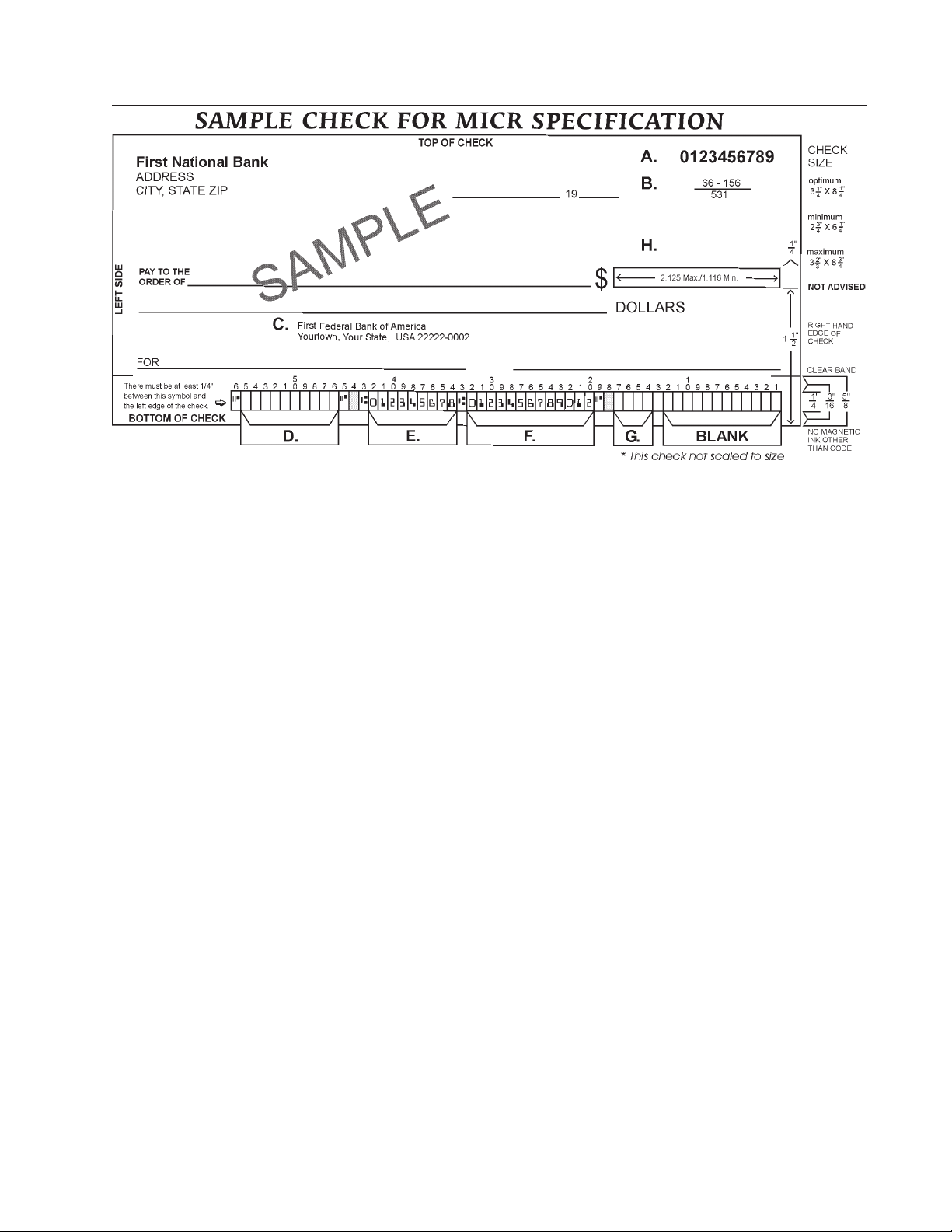
Figure 3.1: Sample Check
A . Serial Number: Must be in the upper right corner and match the serial number in the MICR
line (see D for further explanation).
B. Fractional Routing Transit Number: Should be in the upper right corner and must match
the routing transit number in the MICR line with the exception of the state prefix number
(ex. 66 = NC, 67 = SC, 64 = GA, etc.) and the preceding zeros.
C. Bank Name, State, City: The bank logo is optional. Name of bank, city and state
where the account will be assigned/opened is a required field.
D. Aux On Us (46-55): This is a required field if the customer desires services offered by
the bank which require a serial number. The serial number format is controlled by the
payor’s bank. A & D should match.
E. Routing Number (34-42): Designates the Federal Reserve district and financial
institution. Each city, state or region that the bank serves has a unique institution
identifier. IMPORTANT: positions 35-42 is the Routing Number, position 34 is the
check digit.
F. Account Number: This is a unique number assigned to the customer’s account.
G. Optional Serial Number: Used for personal accounts (checks only). A 4 digit zero
filled field that should match the serial number in the upper right corner.
H. Convenience Amount Area should be in the general location shown above in the
diagram. The illustrated box in the diagram is optional and if used, should conform to ANS
X9.7. A single stroke dollar sign is required.
Secure MICR Printer User’s Guide © Source Technologies
July 2003 Page 9 All rights reserved
Page 14

Section 4: Quality Issues
4 Quality Issues
A high quality MICR document can be read by bank reader/sorter equipment many times
with no readability issues and does not result in damage to bank equipment. This quality is
the result of a well designed printer, an originally manufactured MICR toner cartridge and
high quality check stock.
Printer Features
Y our Secure MICR Printer is equipped with some features to ensure high quality MICR
documents.
Paper Type
We recommend paper trays with check stock be set to “bond” paper type. The
associated “weight” and “texture” settings should be set to “heavy” and “rough.” See the
base printers User’s Guide. If more than one input tray has check stock and they are
the same stock, set all to “bond” and they will be linked. If different stock is used in
more than one input tray , use “custom” type, “rough” and “heavy” to block Linking.
MICR Toner Low Alarm
When MICR toner is low, the printer stops and the user is prompted to load a new
MICR toner cartridge. We do not recommend shaking the cartridge to prolong its
life. Once low toner is sensed, there may not be enough MICR toner left to produce
quality MICR documents.
MICR Toner Sensing
When the printer enters MICR mode and attempts to print a MICR font, it checks to
ensure a MICR toner cartridge is loaded in the printer . If a regular cartridge is present,
an alarm will sound and the user must load a MICR cartridge before their print job will
resume. A message “load MICR Toner” will appear on the Operator’s Panel.
MICR Toner
Use only Source T echnologies MICR toner when printing MICR document s. It is specifically
engineered to print quality MICR documents with your printer . The printers’ MICR toner sensor
is designed to work with the Source T echnologies MICR toner cartridge to prevent printing
checks with regular toner present. Y ou may choose to use this printer for general of fice
printing, which is acceptable. If a MICR print job begins and the printer has a regular toner
cartridge present, the printer will stop and prompt the operator to install a MICR toner
cartridge.
Source Technologies does not recommend the use of refilled MICR toner cartridges.
Although refilled cartridges are generally less expensive, they may result in expensive
printer repairs and bank check reject fees due to inferior MICR toner formulation.
Secure MICR Printer User’s Guide © Source Technologies
July 2003 Page 10 All rights reserved
Page 15

Section 4: Quality Issues
MICR Check Stock
Check stock has a large impact on the resulting quality and security of your MICR document.
Here are a few features that should be considered when selecting a check stock. Please see
Chapter 4 for more information on check stock security features.
Quality
Quality MICR check printing with your ST Secure MICR Printer requires check stock
that matches the printer’s requirements. Source Technologies can supply paper
specifically made for our printers. If you wish to order check stock from other
suppliers, please show the following requirements to your sales representative. We
will test other suppliers’ paper for a nominal fee.
Layout
Layout your check design before any paper is purchased or layout your design to
existing check stock. Keep in mind, perforations, orientation, special logos and any
color elements. The printer can print just about anything as long as it is black.
Weight
We recommend 24 lb. - 29 lb. paper .
Stiffness
We recommend taber M.D. 2.5 and C.D. 1.1 minimum.
Smoothness
For best toner fusing, we recommend rougher surfaces within the base printers’
specifications and the Paper Specifications for Checks X9.18. W e recommend a
smoothness range of 150 to 200 - Sheffield.
Paper Grain Direction
When using 24 lb. - 29 lb. bond paper we generally support either long or short paper
grain. Overall performance in the banks reader/sorters is best when the resultant grain
direction is left to right when viewing the check.
Perforations
All perforations in the stock should be Micro-Perfs (20 or more cuts per inch). Larger
perforations can produce excessive paper chaff and result in damage to the toner
cartridge. Perforations should be ironed by the paper supplier to reduce nesting and
potential double feeding.
Secure MICR Printer User’s Guide © Source Technologies
July 2003 Page 11 All rights reserved
Page 16

Section 4: Quality Issues
Moisture
The paper moisture content should be between 4.7 and 5.5%. Storage conditions have
much to do with the final moisture content of most papers. S tore your check stock in a
cool, dry , environmentally stable and secure area. Protective wrappings should be
removed just prior to use.
Secure MICR Printer User’s Guide © Source Technologies
July 2003 Page 12 All rights reserved
Page 17

Section 5: Security Issues
5 Security Issues
Printing negotiable documents from blank paper on desktop MICR laser printers makes
security a top priority for any company embarking on a desktop check printing project.
Good security programs integrate hardware, software, your employees and your financial
institution into a secure check production system. Recent changes relative to the
responsibilities of banks and their customers have a bearing on the ultimate liability for
fraudulent documents. Customers must have systems designed and documented to show
“Ordinary Care and Good Faith Effort” is in place to avoid liability. In the past, financial
institutions generally credited corporations when fraud was discovered. New regulations
attempt to define who may have been negligent in the transaction and put the liability on
that party or parties. Clearly, if a fraudulent occurrence can be traced to a corporation’s
lack of security procedures, or the design of their negotiable documents, the regulations will
protect the banks, or at best case the loss will be shared.
Check Stock Security Features
We have found the following check stock security features to be of merit:
Artificial Watermarks - White on white printing generally on the back reveals words
or patterns when held at an angle. You should state on the front of the check that
this feature is present. It cannot be copied.
Laid Lines - Evenly spaced background lines that make cut and paste alteration
difficult.
Void Pantograph - Background printing of the word VOID or COPY which appears
on photocopies. Some paper suppliers offer enhanced versions of pantographs
which provide more protection from the latest in color copier technology .
Chemical Additives - If an ink eradicator (bleach, acetone, etc.) is applied to the
document, the eradicator creates a permanent stain.
Numbered Check Stock - Sequential numbering printed in dye that penetrates to
the reverse side of the check can be used to verify authenticity . This number may not
relate to the check serial number. This also provides for inventory control of blank
check stock.
NOTE: These quality issues serve as a general guide for check production. You should not
consider these features as an all inclusive list. We recommend consulting with your local
paper supplier for any additional comments or suggestions.
Secure MICR Printer User’s Guide © Source Technologies
July 2003 Page 13 All rights reserved
Page 18

Section 5: Security Issues
Security Note
Check fraud in the United States is a continuing problem. We have attempted to identify
security features that can be incorporated into the base check stock. However, these may
not prove 100% fraud preventative. Over time, technology will continue to develop new and
improved measures to address check fraud.
The following internal and external security measures will help minimize your risk of check
fraud.
1. Financial institutions should train tellers to look at the check, not the person
presenting the check. The check, not the person, is the item that must be verified.
2. Firms accepting checks should be aware of damaged MICR lines. Intentionally
damaging the MICR line can increase the time necessary to process an item, giving
the forger enough time to leave town. Also be sensitive to discoloration, this could
be an indication of alteration.
3. Incorporate security features into your base check stock and utilize printed
security features that address both alteration and counterfeiting of original items. A
short list of these features would be:
• Warning Bands, or other methods that alert recipients to visual security
features;
• Artificial or genuine watermarks in the base paper;
• Chemical additives in the base paper that react to chemical alteration
attempts;
• Void Pantographs that address attempts to copy original items;
• Unique security fonts that deter attempts to alter payee or amount
information.
4. When generating final negotiable items,
• The document always includes the amount value in words;
• The document should not include information that limits the value range, i.e.
“Not valid over $500.” This only guides the fraudulent attempt. Use your
application software to detect out of range items;
• All levels of hardware and software password protection should be utilized.
5. Safeguard check stock paper, and limit access only to necessary employees.
6. Understand and approve the security procedures of your check stock suppliers to
safeguard stock in their custody.
7. Use “Positive Pay” check services from your financial institution that match check
number and dollar amounts to known information. Financial institutions should
encourage full participation of corporate clients.
Secure MICR Printer User’s Guide © Source Technologies
July 2003 Page 14 All rights reserved
Page 19

Section 5: Security Issues
8. Move methods of fraud detection to the item’s point of entry into the clearing system.
For example, low cost readers can detect low magnetic strength in the MICR line which
is a good indication of attempts to copy an original.
9. Always verify the home address and place of employment of new account
applicants. Use public sources such as phone books to verify phone numbers. Ask
new account applicants why they are opening an account with your institution. Be
suspect of unusual answers or delays in responding.
10. Stay abreast of current check fraud methods and the latest in fraud detection.
Offer seminars to educate corporate clients.
11. Review and document your internal negotiable document printing procedures.
Investigate employee backgrounds before assigning security authority. Split
responsibilities, for example, an accounts payable production/security officer should
not also balance the account.
Secure MICR Printer User’s Guide © Source Technologies
July 2003 Page 15 All rights reserved
Page 20

Section 6: MICR Features
6 MICR Features
Source Technologies’ Secure MICR Printers are designed to allow both general office
document printing and secure MICR document printing. You may print a variety of
conventional jobs with regular Lexmark toner using all of the printer features available such
as MarkNet and MarkVision network attachment interfaces and network printer utilities.
These printers come standard with HP PCL5, PCL6 and PostScript Level 2 emulations and
others. Source T echnologies has designed features to enhance these printers with MICR
mode specific operation that allows you to securely print high quality negotiable documents.
MICR Mode
Your Secure MICR Printer has two operational states: normal and MICR mode. When the
printer is in normal printing mode your MICR resources cannot be accessed. Once the
printer enters into MICR mode your secure resources are available and the printer starts the
process of confirming readiness to print a negotiable document. There are two conditions
which must be met before MICR mode is activated:
If the front panel combination lock feature is activated, the correct eight digit
combination must be entered from the front panel.
The correct password command must be received by the printer from the software
application prior to printing any MICR documents.
MICR Fonts
The E-13B and CMC7 MICR fonts are resident in your printer. Examples of these fonts are
in the Appendix of this manual. They can only be accessed after MICR mode is activated
by your software. A MICR toner cartridge must be present to print the MICR fonts.
Secure Fonts
Two Source Technologies designed secure fonts: Secure Numeric Font and ICR Secure
Numeric Font are resident in your printer. Examples of these fonts are in the Appendix of
this manual. Like the MICR fonts, these secure fonts can only be accessed after MICR
mode is activated by your software.
The ICR Secure Numeric Font is designed for the convenience area of your check. It can
be read by the imaging equipment used by many financial institutions. The Secure
Numeric Font should not be used in this area since the reverse image aspect of this font
prevents it from being read by this equipment. We recommend using both of these fonts
on your checks as they are designed to deter check fraud.
MicroPrint
Y our Secure MICR Printer also contains the MicroPrint font. MicroPrint is text less than .010”
tall. It can easily be read with a magnifying glass but appears to be a solid line to an unaided
Secure MICR Printer User’s Guide © Source Technologies
July 2003 Page 16 All rights reserved
Page 21

Section 6: MICR Features
eye. This font provides protection against reproduction by most scanners and copiers
because they cannot successfully print the tiny letters.
Most check printers use this font in the signature area of their preprinted checks. We
recommend using this font to help deter check fraud. The text in this font can either be
fixed, such as the name of your organization, or it can be variable, such as the check
amount and payee name. The use of variable text provides an additional method of
protection against check counterfeiters.
Use of the “MP” designate symbol to identify the line as MicroPrint is optional. The MicroPrint
font only contains alphanumeric characters. Punctuation marks and spaces are ignored by
this font and do not print.
Bi-Directional Feedback
Your Secure MICR Printer can provide MICR status messages to the check printing
application. This feature is valuable in a networked environment with multiple printers or
with users utilizing a printer located in another area. The application can get information on
MICR settings such as toner cartridge type (MICR or regular), locked trays (which trays are
locked to non-MICR applications), resident fonts/macros and audit trail settings. The printer
can send the application MICR error messages such as “load MICR toner .”
When the printer receives the “@PJL INFO STV ARIABLES” command it will report all MICR
variables to the host. The MICR variables can also be seen by accessing the printer’s front
panel menu. Select Utilities>Print Menus. The second page of this menu shows the current
MICR variable configuration.
If USTATUS DEVICE=On, the printer will report PJL error 40020 for any MICR error which
causes the printer to go off-line. It will appear in this format:
@PJL USTATUS DEVICE
CODE=40020
DISPLAY=”MICR Password Error Press Go”
ONLINE=FALSE (formfeed----HEX 0C)
The code will always be 40020, only the display line will change to indicate the specific
error.
Resource Storage
Check-related resources, such as form overlays and signatures, are stored in your printer with
unique identification numbers. ID numbers must be less than 32767. Number 5001 is
reserved for the Audit Trail overlay . Your Secure MICR Printer has two areas where you may
store these resources: FLASH and RAM Memory .
Secure MICR Printer User’s Guide © Source Technologies
July 2003 Page 17 All rights reserved
Page 22

Section 6: MICR Features
Flash Memory is an optional feature. It is user managed and resources can be designated as
“secure” or “unsecure.” Secure resources are loaded to flash with the STL command and have
ID numbers greater than or equal to 10000. They can only be accessed by using the STP
command when the printer is in MICR mode. Unsecure resources do not require a password
and should be assigned an ID number less than 10000. Resources stored in flash memory
are not deleted when the printer is powered off. Flash memory is required for all Audit Trail
features.
Storing resources in RAM is also an option. Resources in RAM are deleted when the
printer is powered off or reset. For this reason check-related resources may need to be
loaded frequently. Resources stored in RAM cannot be password protected.
We recommend storing all check-related resources in secured flash memory.
MICR Menu
Your Secure MICR Printer contains a front panel menu specific to MICR applications. The
complete menu is as follows:
Security Lock
Audit Menu
Audit Location - Flash/Disk
Record Sorting
Overlay
Sum Field 4
Print Report
Setup Menu
MICR T ype - Normal/Optraforms
Hex Transfer
Density Control
Use the menu button on the front of your printer to toggle through the menu options. T o select
an option press the select (*) button. An item is selected when it has an asterisk (*) after it.
The Security Lock option allows the user to activate and set a front panel combination for
additional security . This feature prevents anyone from printing checks without the proper 8digit combination. See the MICR Mode Commands section of this chapter for more
information.
MICR Type designates the printer as a “normal” Source Technologies Secure MICR Printer
or as a Secure MICR OptraForms Printer . The default is “normal.” Hex Transfer and Density
Control are normally reserved for ST Technocal Support.
Secure MICR Printer User’s Guide © Source Technologies
July 2003 Page 18 All rights reserved
Page 23

Section 6: MICR Features
The Audit Menu deals with the optional Audit T rail Report settings. See chapter 7 for more
information.
Entering MICR Mode
T o print MICR documents, your Secure MICR Printer uses special alphanumeric text
commands called MICR Mode commands.
There are two different commands which activate MICR mode printing:
&%STFPASSWORD$ and &%STHPASSWORD$. The &%STF is the default command
and is recommended for most applications.
T o use the &%STF command, it must be entered at the beginning of the job datastream. The
&%STH command can be entered anywhere prior to accessing secured resources.
The &%STH command is not as powerful as the &%STF command because it does not set
as many parameters for MICR printing. Both commands and descriptions are as follows:
&%STF Command
When entering MICR mode with the &%STF mode, the printer will:
• Check to see if the proper Front Panel Combination has been entered (when
enabled).
• Allow access to secure check printing resources such as MICR fonts and secure
fonts stored in printer ROM.
• Allow access to protected signatures, overlays, logos and other important
resources stored in password protected nonvolatile flash memory.
• Display “MICR Mode Active” on the printer’s front panel.
• Disable the printer’s front panel menu system.
• Set printer resolution to 600 dpi for printing MICR fonts.
• Disable Jam Recovery.
• Set the copies parameter to 1.
• Sets T oner Low Alarm.
• Turn Hex Transfer ON.
NOTE: The &%STF command must be entered at the beginning of the print job
before any other print data is received.
&%STH Command
The &%STH command does not set-up the printer for check printing activity as
completely as the &%STF command mode. This alternate MICR mode command
forces the user to manually program some commands through their host application. It
is used when programmers cannot place &%STFP ASSWORD$ at the beginning of
their job. Use the &%STH command if you experience page ejects while in &%STF
mode.
Secure MICR Printer User’s Guide © Source Technologies
July 2003 Page 19 All rights reserved
Page 24

Section 6: MICR Features
When entering MICR mode with the &%STH command, the printer will:
• Check to see if the proper Front Panel Combination has been entered (when
enabled).
• Allow access to secure check printing resources such as MICR fonts and secure
fonts which are stored in printer ROM. It also allows access to protected
signatures, overlays, logos and other important resources stored in password
protected nonvolatile flash memory.
• Turn Hex Transfer ON.
NOTE: The &%STH command can occur within a datastream after the page has
started. The &%STH command, unlike the &%STF command, can be issued
anywhere on the page.
MICR Mode Commands
Password Command &%STFPASSWORD$ or &%STHPASSWORD$
&%STF or &%STH Lead in sequence
PASSWORD User defined password, 8 characters, case sensitive,
unprintable characters allowed. Factory default is
PASSWORD. See also New Password Command.
$ Command terminator
MICR Definition Command &%SMCPxxxx$ (optional)
&%SMCP Lead in sequence
xxxx MICR count, the number of MICR lines to be printed during
this print job. (4 bytes in hex)
$ Command terminator
Example: &%SMCP0010$
Prints 16 (Hex 10) MICR lines before disabling MICR mode. This command defines how
many MICR lines may print in the current job. When the count decrements to zero, MICR mode
is terminated.
Set New Password Command &%STExxxxxxxx$
&%STE Lead in sequence
xxxxxxxx New password, must be 8 characters either printable or non
printable. Dollar ($) sign is an invalid password character.
$ Command terminator.
Secure MICR Printer User’s Guide © Source Technologies
July 2003 Page 20 All rights reserved
Page 25

Section 6: MICR Features
In order to set a new password the current password must first be sent. Caution: Errors made
in sending the new password command could lead to setting it to an unknown value. If the
Password is unknown the printer must be returned to Source T echnologies to be reset to
PASSWORD.
Activate/Set Front Panel Combination Lock &%STSxxxxxxxx$ (optional)
&%STS Lead in sequence
xxxxxxxx Eight digit sequence, valid characters 0-9
$ Command terminator
Sets and activates the front panel MICR combination lock. If this feature is activated, MICR
mode cannot be entered until the front panel combination is entered correctly. All MICR
features will be inaccessible until this combination is entered. Sending an &%STS
command and eight zeros deactivates the security lock.
Caution: If the front panel combination is set and then forgotten, the printer must be
returned to Source Technologies for the combination to be deactivated.
Print MICR E-13B Font &%SMDddd...ddd$
&%SMD Lead in sequence
ddd...ddd Data to be printed in E-13B MICR font
$ Command terminator
Prints the specified data in the E-13B MICR font which is used in the United States,
Canada and Mexico. The correct spacing begins at the cursor position at the start of the
command. After the terminator is sent, the printer is returned to its default font. After each
Print E-13B command, the MICR count is decremented by one. Upon receiving this command
the printer will check to ensure a MICR toner cartridge is installed and set the copies
parameter to 1. See Appendix A for MICR E-13B font character mapping.
Print MICR CMC7 Font &%SM7ddd...ddd$
&%SM7 Lead in sequence
ddd...ddd Data to be printed in CMC7 font
$ Command terminator
Prints the specified data in the CMC7 MICR font which is used in Europe and South America.
The font and its correct spacing begins at the current cursor position at the start of the
command. Af ter the terminator is sent, the printer will return to its default font, and the MICR
count will be decremented by one. Upon receiving this command the printer will check to
ensure a MICR toner cartridge is installed and set the copies parameter to 1. See Appendix B
for CMC7 character mapping.
Secure MICR Printer User’s Guide © Source Technologies
July 2003 Page 21 All rights reserved
Page 26

Section 6: MICR Features
Print Secure Numeric Font &%SMFddd..ddd~
&%SMF Lead in sequence
ddd...ddd Data to be printed in this font
~ Command terminator
The dollar sign ($) is not a command terminator for this command. For both security fonts
the tilde ~ (hex 7E) is the command terminator since the dollar sign is a valid character.
Print ICR Secure Numeric Font &%SMIxxxxxx~
&%SMI Lead in sequence
xxxxxxxx Data variables to be printed in this font
~ Command terminator
Print MicroPrint Line &%SMMxxxxxxxxx!$
&%SMM Lead in sequence
xxxxxx Data to be printed in this font
! MP designator (optional)
$ Command terminator
If the exclamation point (!) is used, the “MP” designate will print just above and to the right of
the last character . This is optional and is typically used to notify the check recipient of the
presence of MicroPrinting. Only 0-9, A-Z (upper and lower case) print. Special characters
and spaces disappear .
Load Flash Resource &%STLxxxxxyyyyyyzdd....dd
&%STL Lead in sequence
xxxxx Resource number in decimal, must be 5 digits
yyyyyy Byte count of resource file in Hex, must be 6 positions
z Format of the resource file
S = Single byte binary format
D = Double byte text format
dd...dd Flash resource file. e.g. forms overlay, signatures etc.
Resource number values may be between 00001 to 32767. V alues of 10000 and above are
password protected and will require the user to enter MICR mode with a valid password
before they can be unlocked with the STP command. V alues below 10000 will be unsecured.
Secure MICR Printer User’s Guide © Source Technologies
July 2003 Page 22 All rights reserved
Page 27

Section 6: MICR Features
Resource number 5001 is reserved for the Audit Trail overlay , see chapter 7.
Format Flash Memory &%SFF$
&%SFF Lead in sequence
$ Command terminator
This command formats flash memory . A valid p assword command must precede this
command.
Caution: All flash contents will be lost. This includes all electronic forms, signatures, logos, etc.
Secure Flash Resource Unlock Command &%STPxxxxx$
&%STP Unlock flash resource command
xxxxx Flash resource number, must be 5 digits
$ Command terminator
Unlocks a secure flash resource.
Tray Lock Command &%STTL#$
&%STTL Lock tray command
# The tray to be locked (choose from 1, 2 or 3 only)
$ Command terminator
This command prevents other applications from accessing a particular printer paper tray .
Tray Unlock Command &%STTU#$
&%STTU# Unlocks tray
# The tray to be unlocked (choose from 1, 2 or 3 only)
$ Command terminator
Tray Swapping Commands &%STTSON$ / &%STTSOFF$
&%STTSON Turns tray swapping on
&%STTSOFF Turns tray swapping off
$ Command terminator
This command allows you to redefine the PCL values for Trays 2 and 3 to allow software
and operational consistency with older printers in the system. Swapping ON causes any
<esc>&l4H to be replaced with 5H and vice-versa.
Secure MICR Printer User’s Guide © Source Technologies
July 2003 Page 23 All rights reserved
Page 28

Section 6: MICR Features
DES and AES Decryption
Data Encryption Standard (DES) and the recently approved Advanced Encryption Standard (AES) are
both supported in the Source T echnologies Secure MICR Printers. The minimum Code Level support for
AES is 8.5j. Levels 8.5i. and lower only support DES.
DES originated at IBM in 1977 and was adopted by the U.S. Department of Defense. The controlling
standards for DES are ANSI X3.92 and X3.106 and in the Federal FIPS 46-3 standard. An alternative to
DES called Triple DES is not supported in our Secure MICR printers.
AES is documented in a new Federal Information Processing Standard (FIPS) standard
FIPS 197, dated 11/26/2001. Three key sizes are documented in the standard, 128-bit, 192-bit, & 256bit. W e currently only support the most commonly used 128-bit key size.
The algorithm selected for AES is Rijndael. Developed in Belgium, an English pronunciation alternative is
“Rain Doll”. In addition to U.S. Government implementations, it is anticipated AES will be adopted by
businesses, organizations, institutions, and individuals outside of government, and outside of the United
States as was the case for DES.
W e only support decryption for DES and AES. Encrypted printer data streams can be decrypted using the
key stored some time prior to the message. Keys for both DES and AES are supported separately so that
both AES and DES are supported simultaneously . The keys messages themselves can be encrypted with
either DES or AES for either DES or AES. Only one DES and one AES key exists at any one point in
time. Old keys are not saved. T o change either a DES or an AES key requires the MICR Password
Command.
The Secure MICR printer does not have any capability to encrypt a return or Bi-directional message.
Decryption Commands
Decryption requires printer processing overhead. In our testing encrypted printer data steams near or
below 100K bytes per page do not seem to affect printer speed in term of pages per minute or first page
out timings. Some testing done with print files from 500K to 1 Meg per page showed up to a 30% degradation in speed. It is therefore recommended the encryption be reserved for the confidential portions of the
data when large file sizes are anticipated.
Set DES Decryption Key Command&%STSETDESKEY<16 Hex Characters>$
The command requires a MICR Password Command be sent prior to the Key Command. The Key
Command could itself be encrypted and then decrypted in the printer . The command requires the key data
be in a double-byte hex format. The 8 byte value must be converted to the 16 byte format. The only values
that can be contained in the 16 command bytes are 0 through 9, A through F . Alpha key characters can be
upper or lower case. Command characters must be upper case. An example of a valid key & command %STSETDESKEY5f00FF7E3DA938eb$ The key value remains in the printer until another key command
is received. Printer power cycles and printer reset commands do not affect the key value.
The dollar sign ($) is the command terminator and is required.
Secure MICR Printer User’s Guide © Source Technologies
July 2003 Page 24 All rights reserved
Page 29

Section 6: MICR Features
Set AES Decryption Key Command &%STSETAESKEY<32 Hex Characters>$
The command also requires a MICR Password Command be sent prior to the Key Command.
The key data is similar to DES, but is twice in length with 32 Hex character format representing the 16 byte
or 128-bit key value.
T urn DES Decryption ON &%STDON$
T urn AES Decryption ON &%ST AON$
All data following the $ command terminator will be decrypted using the current key value stored in the
printer and the DES or AES algorithm. Decryption continues until a Decryption OFF command is received,
a print Timeout occurs, a printer panel reset occurs, or printer power is cycled. Printer software language
resets do not stop decryption.
T urn DES Decryption OFF &%STDOFF$
T urn AES Decryption OFF &%STAOFF$
The OFF command resides within the encrypted data, and must also be encrypted. The OFF occurs after
an 8-byte block (DES) or 16-byte block (AES) is received and decrypted. The last block containing the
OFF should either have the command right justified or padded out to the block boundary . Any padding
bytes after the $ command terminator will be discarded.
MFP Copy Defeat Commands
A Secure MICR printer with the Multi Function Printer (MFP) feature can scan and copy documents. This
allows the end users to copy MICR documents with MICR toner . The Copy Defeat command will block
the copy function when a MICR toner cartridge is installed, but allow the copy function with standard toner.
MFP MICR Copy Defeat ON &%STMCDON$
MFP MICR Copy Defeat OFF &%STMCDOFF$
Both commands require the MICR Password Command. The ON command blocks the copy function with
MICR toner . The OFF command allows the copy function with MICR toner. The factory default is OFF
Note – Postscript Language print jobs downloaded from a host will not print with MICR toner if the
Postscript job contains a copy count command. Copy Defeat = ON will reset copy count to 0, and nothing
prints. Either the Copy Defeat function needs to be set to OFF or the copy count command needs to be
removed if the user requires Postscript MICR printing. W e tested a few Postscript printer drivers and did
not detect copy count commands, but the specific data streams should be tested.
Secure MICR Printer User’s Guide © Source Technologies
July 2003 Page 25 All rights reserved
Page 30

Customer Character Conversation Command
The Custom Character Conversion Command can be used to resolve some problems in printer data
streams. An example might be to remove a special command character in an existing data stream that was
used by your previous printer hardware. Without changing your data stream, these special characters can
either be removed, converted to Nulls, or converted to other sets of data to accomplish what is required.
An example of this might convert a Skip Command used by an older generation printer to multiple Carriage
Return / Line Feed commands. You could also store a PCL5 command in our SIMM and call it with one
character in your data stream. Only one type of conversion is permitted at any particular point in time, but
the function can be modified within a data stream multiple times.
The conversion information is stored in NVRAM and is retained through power off / power on cycles. This
means you could send the command one time and all future print jobs would be converted. Special precautions are required if printer fonts and Macro’s are downloaded to your printer . This might require you to
disable the function during downloads and re-enable prior to your print data.
&%STCxx[yy ...]$ xx is a double-byte character to convert - the following characters are not allowed:
&, %, S, T, C and $.
yy ...is a double-byte string to convert to - can be 0 to 16 caharcaters long
$ command terminator
Example:
&%STC1E0D0A$ sets the convert character to 1E - the printer will replace any 1E character in the
data stream with 0D 0A (carriage return, line feed)
&%STC1E$ replace 1E with nothing - simply removes all 1E characters from the data
&%STC00$ turn character conversion off
Secure MICR Printer User’s Guide © Source Technologies
July 2003 Page 26 All rights reserved
Page 31

Special Alert and Custom Beep Command
Using the Beep Command, the printer data stream can alert printer operators that important pages are
currently being printed. The STBEEP1 command sounds its special beeps but does not stop the printer .
STBEEP2 stops the printing process and waits for the operator to Press Go.
The Custom BEEP can be used to create an alternative beep pattern to STBEEP1. This could be used to
indicate a certain document, a custom signal to a different operator, or just an alternative of your choice to
STBEEP1. The Custom Beep command will not stop the printing process.
NOTE: Beep Commands will not chain or link together. You cannot play Beethoven’s 5th Symphony . During the
execution of a beep pattern, all other beep commands are eaten. Two important documents could be sent to the printer
one after the other, both with beep commands, but the pattern would only occur one time.
NOTE: The two digit frequency value is inverted. The higher the value, the lower the frequency .
&%STBEEP1$ plays 3 long beeps, 3 short beeps, 3 long beeps and 3 short beeps.
&%STBEEP2$ displays the message “Press Go to stop beeping” on the front panel and
repeatedly plays 5 long beeps.
&%STBEEPnnffdddd$ plays a custom beep -
nn is a two digit number of beeps (0-63)
ff is a two digit frequency (0-63)
dddd is a four digit duration (0-1023)
Example:
&%STBEEP02250300$ plays 2 long (duration 300) beeps at a frequency of 25.
Secure MICR Printer User’s Guide © Source Technologies
July 2003 Page 27 All rights reserved
Page 32

Section 7: IBM Host Programming Features and Examples
7 IBM Host Programming Features and Examples
Hex Transfer
The Hex Transfer feature allows the user to send PCL escape sequence printer commands to
the printer with simple text strings. Y ou may send any valid command or string of commands
with no limit on the length or complexity . Form macros, signatures, or simple commands may
be passed through any platform to the printer since they are simple text. The printer will convert
them back to ESC (escape) sequences when they arrive at the printer . Hex Transfer is
automatically enabled while in MICR Mode. T o enable it for all applications use the following
commands:
Turning Hex Transfer On
T o enable Hex T ransfer, send the following command::
&&??&%
Once Hex Transfer is enabled, the character sequence &% will act as a trigger sequence. Any
data following these trigger characters will not be printed and will be treated as Hex T ransfer
data until the Hex T ransfer ending character $ is encountered.
T urning Hex Transfer Off
T o turn Hex T ransfer off, send the following command:
&&??!!
This command will clear the trigger sequence and allow the &% characters to print. This clear
command may be sent at any time to assure that Hex Transfer is disabled. When MICR Mode
is entered, Hex T ransfer will automatically be turned on, and when MICR Mode is exited, Hex
Transfer will be turned off unless it has previously been activated out side of MICR Mode with
the &&??&% string.
Secure MICR Printer User’s Guide © Source Technologies
July 2003 Page 28 All rights reserved
Page 33

Hex Transfer Examples
&&??&% This command enables Hex Transfer
On
&%1B 26 6C 34 48 $
or
&% 1B $& l 4H Sends the PCL Esc sequence:
<Esc>&l4H
which is a paper source command
identifying what tray the paper will be
pulled from.
&% 1B 45$
or
&% 1B $E This command is a printer reset PCL
command which consist of the Esc
character and printable E character
and may be sent by simply putting the
Esc character in Hex.
Note - Hex Transfer can now be set ON or OFF via the MICR Menu. See Section 6, MICR
Menu
Secure MICR Printer User’s Guide © Source Technologies
July 2003 Page 29 All rights reserved
Page 34

Section 7: IBM Host Programming Features and Examples
Figure 7.1 MICR Mode Command Example
The following example shows the MICR Mode commands and Hex Transfer commands in
use. This datastream would print the check on the following page (assuming the check
macro and the signature are loaded as flash resources).
&%STFPASSWORD$ &%SMCP0001$ &%STP10001$ &%STP20000$
&%1B266C3178307331683261366346306F3165316C372E3330431B2661304C1B2873
3130481B266B31302E3030481B26663130303031793358$
1000
200 Vendor Systems
October 5, 2005
99999 Oct 1 05 1000.00 20.00 980.00
1234567 Oct 2 05 200.00 4.00 196.00
136784 Oct 3 05 800.00 16.00 784.00
555555 Oct 3 05 55.55 1.11 54.44
2055.55 41.11 2014.44
200 Vendor Systems
99999 Oct 1 05 1000.00 20.00 980.00
1234567 Oct 2 05 200.00 4.00 196.00
136784 Oct 3 05 800.00 16.00 784.00
555555 Oct 3 05 55.55 1.11 54.44
2055.55 41.11 2014.44
&%1B$(s1p16v0s3b4148T 1000 &%1B$(3@
October 5, 2005
&%SMF$2014.44~
&%1B$(s0p12h1s0b4099T
*********** Two Thousand Fourteen and 44/100*******DOLLARS &%1B$(3@
$2014.44
Vendor Systems
927 Warehouse Road
Kansas City , MO 59782 &%1B$(20000X ! &%1B$(3@
1000
October 5, 2005
&%1B$&f0S &%1B$*p296x3184Y &%SMD;00001000; :123456789:1234567890123:$
&%1B$&f1S
Secure MICR Printer User’s Guide © Source Technologies
July 2003 Page 30 All rights reserved
Page 35

Figure 7.2: Sample Check
DUPLICATE FILE COPY CHECK NO: 1000
VENDOR NO: 200 NAME: VENDOR SYSTEMS CHECK DATE: October 5, 2005
REFERENCE NUMBER INVOICE DATE GROSS AMOUNT DISCOUNT TAKEN NET AMOUNT PAID
99999
1234567
136784
555555
Oct 1 05
Oct 2 05
Oct 3 05
Oct 3 05
Section 7: IBM Host Programming Features and Examples
1000.00
200.00
800.00
55.55
20.00
4.00
16.00
1.11
980.00
196.00
784.00
54.44
TOT ALS
VENDOR NO: 200 NAME: VENDOR SYSTEMS CHECK DATE: October 5, 2005
REFERENCE NUMBER INVOICE DATE GROSS AMOUNT DISCOUNT TAKEN NET AMOUNT PAID
99999
1234567
136784
555555
Oct 1 05
Oct 2 05
Oct 3 05
Oct 3 05
TOT ALS
2910 Whitehall Park Drive
Charlotte, NC 28273
(704) 969-7500
Pay
2055.55 41.11
1000.00
200.00
800.00
55.55
2055.55 41.11
First National Bank
of Any State
Any City, NC 27514
CHECK NO: 1000
20.00
4.00
16.00
1.11
CHECK No. 1000
DA TE October 5, 2005
2014.44
980.00
196.00
784.00
54.44
2014.44
66-156
531
*********** T wo Thousand Fourteen and 44/100 ***********DOLLARS
VOID
To the
Order of
Secure MICR Printer User’s Guide © Source Technologies
July 2003 Page 31 All rights reserved
V endor Systems
927 W arehouse Road
Kansas City , MO 59782
;00001000; :123456789:1234567890123;
AMOUNT $2014.44
NON-NEGOTIABLE
Page 36

Section 7: IBM Host Programming Features and Examples
The commands in Figure 7.1 in order of appearance:
&%STFPASSWORD$ Password Command.
&%SMCP0001$ MICR Definition Command with the count set to one.
&%STP10001$ Unlock Flash Resource number 10001.
&%STP20000$ Unlock Flash Resource number 20000.
&%1B26...3358$ PCL sequence in hex which sets the page format and
enables macro number 10001.
&%1B$(s1p16v0s3b4148T PCL sequence which changes the font to Univers 16 point.
After the check serial number prints (1000), the printer is
returned to its default font with the following command.
&%1B$(3@ PCL command to return to default font.
&%SMF$2014.44~ Print Secure font command. Note: The tilde ~ is the
command terminator.
&%1B$(s0p12h1s0b4099T PCL command to change the font to Courier 12 pitch Italic.
Print PCL Fonts from the Front Panel menu for a list of fonts
with their call commands.
&%1B$(3@ PCL command to return to the default font.
&%1B$(20000X! PCL command to print font number 20000. In this example
font 20000 is a signature previously loaded into flash memory .
Here we call it and print it with an exclamation point (!).
&%1B$(3@ PCL command to return to the default font.
&%1B$&f0S PCL command to Push (store) the current cursor position.
&%1B$*p296x3184Y PCL command to move the cursor to 296X , 3184Y. At 300
units of measure, this is .97 inches across and 10.61 inches
down. We are precisely positioning the MICR line.
&%SMD....$ Print E-13B MICR Command. Prints the MICR line. Note
the MICR font character mapping in Appendix A.
&%1B$&f1S PCL command to Pop (return) the cursor to the pushed
position.
Secure MICR Printer User’s Guide © Source Technologies
July 2003 Page 32 All rights reserved
Page 37

Section 7: IBM Host Programming Features and Examples
Escape Character Translation
In many IBM host environments, the programmer cannot send an ESC character (ASCII
hex 1B) to the printer from within the application. Your Secure MICR Printer allows you to
define the ESC character as a printable character or a combination of two printable
characters. You can select combinations of 1 or 2 characters which are translated to a Hex
1B when they are sent to the printer .
The command &%STYxxyy$ is used to select the character or character combination. The
pair xx represents the first characters’ ASCII hex value, yy represents the second
characters hex value.
Example: The symbols @@ should be translated into the escape character:
&%STY4040$
After this is sent to the printer , anytime an @ @ is received in exact sequence, the pair is
translated into the ESC character (Hex 1B). A single @ would print normally .
If yy is equal to 00, only the first character is used for the escape character.
Example: The symbol @ should translate into the escape character:
&%STY4000$
After this is sent to the printer , anytime an @ is received it is translated into the ESC character.
This means that the printer will never print the @ character . The only invalid single characters
are the & (HEX 26) and a null (00).
Example: &%STY2300$ #&l8D
The printer would translate the number sign (Hex 23) to the ESC character and it would act
on the sequence Esc&l8D which will set line spacing to 8 lines per inch.
If you want to reset the ESC character translation from the previous settings then you can send
the &%STY Command to deactivate the translation.
Example: &%STY0000$
Secure MICR Printer User’s Guide © Source Technologies
July 2003 Page 33 All rights reserved
Page 38

Section 8: Audit Trail Reports
8 Audit Trail Reports
The Audit Trail Report feature provides a report of the printer’s MICR printing activity . The
printer must have flash memory to utilize this option. Details of each flagged check record sent
to the printer are provided since the last audit report was purged from flash memory .
Report Details
A record (check) must be bounded by a start of record command and an end of record
command. Within each record, fields to be included in the Audit Trail Report must be flagged.
The printer stores each record in flash memory . After the check is successfully printed, its
record is designated as a successfully printed document in flash.
The report is built by printing each one of these check records as a line item. At the end of the
report, an exception report is generated which highlights any records received by the printer
but not successfully printed.
Each record (check) has a maximum of seven fields with a total of 146 bytes. Two of the
flagged fields, SQ1 and SQ7 are Audit Report fields only. They are not printed on the
MICR document. Flagging other fields for inclusion in the Audit Report does not effect how
they print on a check.
Audit T rail Menu
The MICR menu contains a section for the Audit Trail options. Menu options are Record
Sorting, Overlay, Sum Field 4 and Print Report.
Audit Record Sorting
Enables sorting of the report by the first 20 digits in the MICR line field. In an unsorted
report the records are in the order in which they were printed.
Overlay
To assist in reading an Audit Trail report you have the option of using a form overlay. This
overlay can provide lines, boxes and shading for a more user friendly report format.
The Audit Trail Report overlay can be stored in printer flash or RAM. We recommend
storing it in flash. It must have an ID of 5001. It is enabled by accessing the MICR menu via
the printer’s front panel. Select Audit Menu>Overlay . This overlay will now be merged with the
record details every time the Audit Trail Report is printed.
Sum Field 4
The values in field four of the Audit Trail Report can be added together with the total
provided at the end of the report. This feature is activated through the MICR menu. Select
Audit Menu>Sum Field 4.
The values in field 4 must follow certain guidelines to be included in the column summation.
Dollar signs and commas must be properly located, no more than two numbers after a decimal
Secure MICR Printer User’s Guide © Source Technologies
July 2003 Page 34 All rights reserved
Page 39

Section 8: Audit Trail Reports
point, and no alpha characters. For example:
Valid Formats Invalid Formats
“$1,234,567.89” “$1,23,”
“4321234.56” “432.123”
“5,321” “34 test”
“$.89” “12$123”
If the value in field 4 is in an invalid format, that line will have a question mark to the right of
the field and it will not be added to the total. Under these circumstances, the total will print
with the notation “Fields flagged with ‘?’ not included in total.”
If the total exceeds $4,294,957,295.99 the printer will print an error message “Total exceeds
maximum value” instead of the total.
Print Audit Report
Prints an Audit Trail Report.
The Audit Trail Report is also part of the command set so the Audit Report can be printed
and purged via the host application. As a security control mechanism, purging is only
possible after entering a valid password.
The printer can store approximately 6,000 records or checks for each megabyte of flash. If
the Audit Report feature is activated, and the printer’s flash memory becomes full, an error
condition occurs. The printer will stop printing and prompt the operator to print and purge the
Audit Report memory. See the following section for purge instructions.
Secure MICR Printer User’s Guide © Source Technologies
July 2003 Page 35 All rights reserved
Page 40

Section 8: Audit Trail Reports
Audit Trail Report Command Set
&%SAR$ Start Audit Record
&%SAR Lead in sequence
$ Command terminator
Marks the start of an audit record and begins a PJL job.. This command must be inserted in
the datastream after MICR Mode is entered and before the first flagged field appears. It
should be sent at the beginning of each check record.
End Audit Record &%STORE$
&%STORE Lead in sequence
$ Command terminator
Ends the Audit Record and the PJL job (ignored if there was no Start Audit Record
Command).
Audit Report Field One &%SQ1d..d$
&%SQ1 Lead in sequence
d..d Data to be stored
$ Command terminator
This command identifies the data to be printed in the first column of the report. It is a
maximum of 14 characters in length. If less than 14 characters are sent, the printer fills the
field with spaces when the audit report is printed. This field is recorded in the audit report
only, it is not printed on the check.
Audit Report Field T wo-MICR Line &%SMDd..d$ or &%SM7d..d$
&%SMD or &%SM7 Lead in sequence
d..d Data to be printed
$ Command terminator
This command identifies the data to be printed in the second column of the report. It is a
maximum of 40 characters in length.
Audit Report Field Three &%SQ3d..d$
&%SQ3 Lead in sequence
d..d Data to be printed
$ Command terminator
This command identifies the data to be printed in the third column of the report. It is a
maximum of 40 characters.
Secure MICR Printer User’s Guide © Source Technologies
July 2003 Page 36 All rights reserved
Page 41

Section 8: Audit Trail Reports
Audit Report Field Four &%SQ4d..d~
&%SQ4 Lead in sequence
d..d Data to be printed
~ Command terminator
This command identifies the data to be printed in the fourth column of the report. It is a
maximum of 16 characters in length. Since a total of this field can be provided at the end
of the Audit Trail Report it is typically used for the convenience amount field. NOTE: This is
the only command where the $ is not a command terminator. The tilde ~ (hex 7E) acts as
the command terminator.
Audit Report Field Five &%SQ5d..d$
&%SQ5 Lead in sequence
d..d Data to be printed
$ Command terminator
This command identifies the data to be printed in the fifth column of the report. This field is
a maximum of eight characters.
Audit Report Field Six &%SQ6d..d$
&%SQ6 Lead in string
d..d Data to be printed
$ Command terminator
This command identifies the data to be printed in the sixth column of the report. This field
is a maximum of 19 characters.
Audit Report Field Seven &%SQ7d..d$
&SQ&7 Lead in string
d..d Data to be stored
$ Command terminator
This command identifies the data to be printed in the seventh column of the report. This
field is a maximum of 12 characters. The data in this field is recorded for the Audit Report
only .
Secure MICR Printer User’s Guide © Source Technologies
July 2003 Page 37 All rights reserved
Page 42

Section 8: Audit Trail Reports
Print and Purge Audit Report &%SPURGExx$
&%SPURGE Lead in string
x option(s)
$ Command terminator
This command prints and purges the Audit Report. All recorded information is deleted. The
optional field can be any combination of the following letters:
T T ot al Field 4
O Overlay
S Sort by MICR line
C Communicate - send report to host instead of printing - see additional
information below on SPRINT command
For example, the command &%SPURGES$ sorts the records by the MICR line while the
command &%SPURGESO$ sorts the records by the MICR line and prints an overlay with
the data.
Options can be forced on with these commands but they cannot be forced off. In other
words, if the front panel overlay setting is on, it cannot be forced off by a datastream
command. If the front panel overlay setting is off, however, a datastream command can
activate this feature. This command can only be accessed with a valid password
command.
Print Audit Report &%SPRINTxx$
&%SPRINT Lead in string
x option(s)
$ Command terminator
Prints the Audit Report
The optional field can be any combination of the following letters:
T T ot al Field 4
O Overlay
S Sort by MICR line
U Unsuccessful report only
C Communicate - send report to host instead of printing
The report sent back to the host begins with SOH (0x01) and ends with EOT (04). Since the
reports can be quite long, they will likely be broken into separate buffers which may be
interspersed with non-audit buffers such as PJL JOB status. Each buffer will begin with an
STX character (0x02) and end with ETX (0x03).
Each record will be terminated with carriage return-line feed (0x0D 0A).
Secure MICR Printer User’s Guide © Source Technologies
July 2003 Page 38 All rights reserved
Page 43

Start Audit Feedback Command
&%SAF$
The printer will report to the host that sent this command every time an audit job
successfully prints.
Each report will be a 151 byte string:
byte 1 STX (0x02)
bytes 2-15 field 1 of the audit record (from SQ1)
16-55 field 2 (from SMD)
56-95 field 3 (from SQ3)
96-111 SQ4
112-119 SQ5
120-138 SQ6
139-150 SQ7
151 ETX (0x03)
The printer will continue to report until it is powered off and back on.
Secure MICR Printer User’s Guide © Source Technologies
July 2003 Page 39 All rights reserved
Page 44

Section 8: Audit Trail Reports
Figure 8.1 Audit Trail Commands Example
The following example shows the Audit Trail, MICR Mode and Hex Transfer commands in
use.
&&??&% &%STFPASSWORD$ &%SMCP0001$ &%SAR$ &%STP10001$ &%STP20000$
&%1B266C3178307331683261363466306F3165316C372E3330431B2661304C
1B28733130481B266B31302E3030481B26663130303031793358$
1000
&%SQ1200$200 Vendor Systems
Oct. 5, 2005
99999 Oct 1 05 1000.00 20.00 980.00
1234567 Oct 2 05 200.00 4.00 196.00
36784 Oct 3 05 800.00 16.00 784.00
555555 Oct 3 05 5 5.00 1.11 54.44
2055.55 41.11 2014.4
1000
20 0 Vendor Systems Oct. 5, 2005
99999 Oct 1 05 1000.00 20.00 980.00
1234567 Oct 2 05 200.00 4.00 196.00
136784 Oct 3 05 800.00 16.00 784.00
555555 Oct 3 05 55.55 1.11 54.44
2055.55 41.11 2014.44
&%1B$(s1p16v0s3b4148T1000&%1B$(3@
&%SQ6October 5, 2005$
&%SMF$2014.44~
&%1B$(s0p12h10v1s0b4099T
***********Two Thousand Fourteen and 44/100*******DOLLARS &%1B$(3@
&%SQ4$2014.44~
&%SQ3 Vendor Systems$
927 Warehouse Road
Kansas City, MO 59782 &%1B$(20000X ! &%1B$(3@
&%1B$&f0S &%1B$*p296x3184Y &%SMD;00001000; :123456789:1234567890123:$
&%1B$&f1S &%SQ710:33:45 AM$ &%STORE$ &&??!!
Secure MICR Printer User’s Guide © Source Technologies
July 2003 Page 40 All rights reserved
Page 45

Figure 8.2 Audit Trail Check Sample
Section 8: Audit Trail Reports
The datastream in Figure 7.1 will print the following check (assuming the check macro and
signature are loaded as flash resources).
DUPLICATE FILE COPY CHECK NO: 1000
VENDOR NO: 200 NAME: VENDOR SYSTEMS CHECK DATE: October 5, 2005
REFERENCE NUMBER INVOICE DATE GROSS AMOUNT DISCOUNT TAKEN NET AMOUNT PAID
99999
1234567
136784
555555
Oct 1 05
Oct 2 05
Oct 3 05
Oct 3 05
1000.00
200.00
800.00
55.55
20.00
4.00
16.00
1.11
980.00
196.00
784.00
54.44
TOT ALS
VENDOR NO: 200 NAME: VENDOR SYSTEMS CHECK DATE: October 5, 2005
REFERENCE NUMBER INVOICE DATE GROSS AMOUNT DISCOUNT TAKEN NET AMOUNT PAID
99999
1234567
136784
555555
Oct 1 05
Oct 2 05
Oct 3 05
Oct 3 05
TOT ALS
2910 Whitehall Park Drive
Charlotte, NC 28273
(704) 969-7500
Pay
VOID
2055.55 41.11
1000.00
200.00
800.00
55.55
2055.55 41.11
First National Bank
of Any State
Any City, NC 27514
CHECK NO: 1000
20.00
4.00
16.00
1.11
CHECK No. 1000
DA TE October 5, 2005
2014.44
980.00
196.00
784.00
54.44
2014.44
66-156
531
*********** T wo Thousand Fourteen and 44/100 ***********DOLLARS
VOID
To the
Order of
Secure MICR Printer User’s Guide © Source Technologies
July 2003 Page 41 All rights reserved
V endor Systems
927 W arehouse Road
Kansas City , MO 59782
C00001000C B123456789B1234567890123B
AMOUNT $2014.44
NON-NEGOTIABLE
Page 46

Section 8: Audit Trail Reports
The commands in Figure 8.1 in order of appearance. (Audit Report fields shown in
bold)
&&??&% Hex transfer enable.
&%STFPASSWORD$ Password command.
&%SMCP0001$ MICR definition command with the count set to one.
&%SAR$ Activates Audit Report recording.
&%STP10001$ Unlock flash resource number 10001.
&%STP00200$ Unlock flash resource number 200.
&%1B26...3358$ PCL sequence in hex which sets the page format and
enables macro number 10001.
&%SQ1200$200 Stores the vendor number 200 in the first position of the Audit
Report. Note that this field will not be sent to the page to be
printed. Here we send the field again so that it will print.
&%1B$(s1p16v0s3b4148T PCL sequence which changes the font to Univers 16 point.
After the check serial numbers prints (100), the printer is
returned to its default font with the following command.
&%1B$(3@ PCL command to return to default font.
&%SQ6October 5, 2005$ Stores the date in the sixth position of the Audit Report.
&%SMF$2014.44~ Prints Secure Font command. NOTE: Tilde (~) is
command terminator.
&%1B$(s0p12h10v1s0b4099T PCL command to change the font to Courier 12 pitch Italic.
See print PCL Fonts on the Front Panel under the test
menu for a printout with their call commands.
&%1B$(3@ PCL command to return to the default font.
&%SQ4$2104.44~ Stores the amount in the fourth position of the Audit Report.
&%SQ3Vendor Systems $ S tores the payee, V endor Systems, in the third position of the
Audit Trail report.
&%1B$(200X! PCL command to print font number 200. In this example font
200 is a signature previously loaded into flash memory.
Here we call it and print it with an exclamation point (!).
Secure MICR Printer User’s Guide © Source Technologies
July 2003 Page 42 All rights reserved
Page 47

Section 8: Audit Trail Reports
&%1B(3@ PCL command to return to the default font.
&%1B$&f0S PCL command to push (store) the current cursor position.
&%1B$*p296x3184Y PCL command to move the cursor to 296X, 3184Y. At 300
dpi, this is .97 inches across and 10.61 inches down. We
are precisely positioning the MICR line.
&%SMD...$ Print E-13B MICR command. Prints the MICR line and
stores the MICR line information in the second position in
the Audit Report.
&%1B$&f1S PCL command to pop (return) the cursor to the pushed
position.
&%SQ710:33:45 AM$ Here we send the time of print to the printer. The data is
recorded in the Audit Report but this field is not printed on the
page.
&%STORE$ Signals the end of a check and the end of Audit Report
recording.
&%??!! Turns Hex Transfer off.
Secure MICR Printer User’s Guide © Source Technologies
July 2003 Page 43 All rights reserved
Page 48

Section 8: Audit Trail Reports
Figure 8.3 Audit T rail Report
Audit Report page1 Records 1 through 10 of 10 *indicates check did not print **indicates gap in check numbers
200 :00001000; :123456789: 12345678912345678: Vendor Systems $2,014.44 February 10, 2001 10:33:44 AM
200 :00001001; :562478923: 12345678912345678: Classic Homes Construction $28,576.72 February 12, 2001 09:45:40 AM
200 :00001002; :285946731: 12345678912345678: Computer Source, Inc. $55,600.00 February 14, 2001 01:00:26 AM
MSMITH :00001003; :628499761: 12345678912345678: Eastern Cleaning Supplies $876.00 February 15, 2001 08:45:36 AM
MSMITH :00001004; :559873164: 12345678912345678: Dillon Consulting Company $1,200.00 February 15, 2001 08:46:50 AM
MSMITH ** :00001006; :578642315: 12345678912345678: Klaussen Enterprises $449,466,800.00 February 15, 2001 08:47:32 AM
MSMITH :00001007; :556791324: 12345678912345678: Woods Paper Products $89.95 February 15, 2001 08:49:45 AM
*PJONES :00001008; :256988974: 12345678912345678: Printers Quarterly $899.99 February 19, 2001 09:35:40 AM
Administrator :00001009; :123654987: 12345678912345678: XYZ Insurance $123,568.00 February 21, 2001 10:30:45 AM
T53DODER :00001010; :155554897: 12345678912345678: Carmine’s Deli $2,354.00 February 22, 2001 11:15:25 AM
SQ1=14 spaces SMD=40 spaces SQ3=40 spaces SQ4=16 spaces SQ5=8 spaces SQ6=19spaces Q7=12 spaces
1 2 3 4 5 6
7
NOTE: Each of the seven fields in the Audit Report holds a maximum number of characters. Those numbers
are represented in BOLD above with their corresponding fields. Field 1 and Field 7 will not print on the check.
This Audit Report is just one example of a report format. Any of the seven fields can be
manipulated to show any information the user feels is appropriate. For example, the check
amount could be in field 3 rather than field 4; or field 5 could contain items such as taxes drawn
on the check, check numbers, year-to-date accumulations, etc.
Each line is a record of a check that was printed. The top of every Audit Trail Report
shows how many pages make up the report as well as the number of records that will print.
The Audit Report can be printed in two ways: a sorted report or an unsorted report. A
sorted report sorts all checks numerically by the first 20 characters in the MICR line field
and prints asterisks (**) beside checks printed out of sequence. Sorting can be done via
the front panel or by the commands &%SPRINTS$ or &%SPURGES$. An unsorted report lists
checks in the order they were printed. An asterisk(*) at the beginning of a line states that the
check number did not print.
In this example:
SQ1= The authorized user who accessed the Audit Trail Report.
SMD=Displays the client’s check number , the bank institution’s routing number, and
account number.
SQ3= The name of the payee (The name of the person or organization to whom the
check was made payable).
SQ4= The amount of the check.
SQ5= Not used in this report.
SQ6= The date the check was written.
SQ7= The time that the check was printed.
All of the above fields will be printed on the check with the exception of field 1 and field 7.
Secure MICR Printer User’s Guide © Source Technologies
July 2003 Page 44 All rights reserved
Page 49

Section 9: Error Messages
9 Error Messages
Your Secure MICR Printer has a set of front panel error messages unique to MICR
applications. These messages appear if there is a MICR related problem. The printer may
also print an error message on the page near where the error occurred. In many cases you
can receive more information about a displayed error by pressing Go to print the job which
caused the error . Then inspect the printed page for a more detailed error message.
See list of MICR Error Messages on following page.
Secure MICR Printer User’s Guide © Source Technologies
July 2003 Page 45 All rights reserved
Page 50

Error Message
on Display Printed Message Description Action
Can’t Purge Pswd not
enabled
Can’t Sort Insufficient
Memory
Command Decode Error
Convert to Esc Error
Flash Full Purge and
Format
Load MICR T oner
Macro Definition Error
Macro Definition Error
Macro Definition Error
Macro Definition Error
Macro Definition Error
Macro Transfer Error
Macro Transfer Error
MICR Definition Error
MICR Password Error
MICR Password Error
MICR Password Error
Security Lock Error
Security Lock Error
Decode error &%Sx
(where x is the
incorrect character)
Invalid Convert to
Escape Character
Invalid decode mode
specified
Macro ID already in
use on SIMM. Print
menus to see a list
of used ID’s.
Macro size exceeds
available space
Non-hexadecimal
value received.
Non integer value
received.
Integer string
incorrect length
Non-integer value
received.
Password Length
Error.
Password Match
Error
Security Lock Not
Enabled Error.
Integer string
incorrect length.
Non-integer value
received.
This error indicates that MICR mode has not
been enabled.
This error indicates the printer does not
have sufficient memory to sort the Audit
Report.
A syntax error was detected in a MICR
command.
An error was detected in the User
Programmable Escape Character Selection
Command. The software tried to specify a
NULL or an ampersand as the first Escape
Character.
This error message indicates that the
printer’s flash memory is full. The audit trail
cannot accept more jobs until more space
is available in flash.
Before printing a MICR font, the printer
checks for MICR toner. If regular toner is
present, the printer will stop all printing and
display this message.
The Load Flash Resource Command
contained an invalid character specifying
the format of the file. Must be either a D or
S.
The resource number in the Load Flash
Resource Command (&%STL...) was over
the 32767 list.
Flash resource file size specified in the
Load Flash Resource Command is too large
fro the available space remaining in the
flash module.
The Load Flash Resource Command
contained a non-hexadecimal value in the
byte count parameter.
The resource number in the Load Flash
Resource Command (&%STL...) was not
five integers.
The Flash Resource Number in the Secure
Flash Resource Unlock Command was not
five digits in length.
The Secure Flash Resource Unlock
Command contained a non-integer value.
The number of digits in the MICR definition
Command is not equal to four, or there is a
non-hexadecimal character in the count.
Password length is not equal to eight
characters.
Password sent does not match the current
stored password.
Front panel combination feature has been
enabled but was not entered before a MICR
job was started.
An error was detected in the Activate/Set
Front Panel Combination Lock Command.
The combination must be eight digits in
length.
An error was detected in the Activate/Set
Front Panel Combination Lock Command. A
character was received in the command
that was a non-integer.
Press Go. Enter MICR mode, then
re-attempt the purge.
Press Go. The printer may need
to be upgraded with more RAM
memory to sort; otherwise an
unsorted Audit Report may be
printed.
Check your software for a
syntax error in the MICR
command that was being used
when the error occurred.
Check the Command (&%STY...)
for errors.
Press Go then purge the audit
trail. Then either defragment or
format flash memory (Utilities
Menu).
Replace standard toner cartridge
with a MICR Toner. Go to
proceed. If MICR toner is not
available, you must power-off
your printer and restart the print
job at a later time when MICR
toner is available.
Check the Command (&%STL...)
for syntax errors.
Check the Load Flash Resource
Command for syntax/numbering
errors.
Format flash memory to remove
all existing resources or upgrade
flash memory to a larger module.
Check the Command (&%STL...)
syntax for errors.
Check the command for syntax/
numbering errors.
Check the Command (&%STP ...)
for syntax/numbering errors.
Check the Command (&%STP ...)
for syntax/numbering errors.
Check your software for errors in
the MICR definition Command.
Check the Password Command in
your software, it must be eight
characters long.
Check the Password Command in
your software.
From the front panel select MICR
Menu>Security Lock and enter
the correct combination. Press
Go to resume the print job.
Check the Activate/Set Front
Panel Combination Lock Command
in your software.
Check the Activate/Set Front
Panel Combination Lock Command
syntax in your software.
Secure MICR Printer User’s Guide © Source Technologies
July 2003 Page 46 All rights reserved
Page 51

Appendix A: E13B MICR Font Mapping
Command &%SMDddd..ddd$
MICR Font Description Alpha/Numeric Hex Values
Character Values
//
/ Amount Symbol A a / 41 61 2F
//
::
: Transit Symbol T t B b : 54 74 42 62 3A
::
;;
;
;;
==
=
==
On-Us Symbol O o C c ; 4F 6F 43 63 3B
Dash Symbol V v D d - = 56 76 44 64 2D 3D
1
0 Zero 0 30
1 One 1 31
2 Two 2 32
3 Three 3 33
4 Four 4 34
5 Five 5 35
6 Six 6 36
7 Seven 7 37
8 Eight 8 38
9 Nine 9 39
Example: &%SMD ;00001234; T01234567T3210987654321;$ will print:
1
Select only one alphanumeric character to call the font.
;00001234; :01234567:3210987654321;;00001234; :01234567:3210987654321;
;00001234; :01234567:3210987654321;
;00001234; :01234567:3210987654321;;00001234; :01234567:3210987654321;
Secure MICR Printer User’s Guide © Source Technologies
July 2003 A1 All rights reserved
Page 52

Appendix B: CMC7 MICR Font Mapping
Command &%SM7ddd..ddd$
Description Alpha/Numeric Hex Values CMC7 Font
Characters Values
1
Zero 0 30
One 1 31
Two 2 32
Three 3 33
Four 4 34
Five 5 35
Six 6 36
Seven 7 37
Eight 8 38
Nine 9 39
Colon : 3A
Semi-Colon ; 3B
Less Than < 3 C
Equal = 3D
Greater Than > 3E
1
The CMC7 Font in the example above is magnified for purposes of clarity .
Secure MICR Printer User’s Guide © Source Technologies
July 2003 A2 All rights reserved
Page 53

Appendix C: Secure Numeric Font Mapping
Command &%SMFddd...dd~
Description Alpha/Numeric Hex Value Secure Font Character
Character
Dollar Sign $ 23
Left Bracket ( 28
Right Bracket ) 29
Asterisk * 2A
Comma , 2C
Dash - 2D
Period . 2E
Slash / 2F
Zero 0 30
One 1 31
Two 2 32
Secure MICR Printer User’s Guide © Source Technologies
July 2003 A3 All rights reserved
Page 54

Appendix C continued: Secure Numeric Font Mapping
Description Alpha/Numeric Hex Value Secure Font Character
Character
Three 3 33
Four 4 34
Five 5 35
Six 6 36
Seven 7 37
Eight 8 38
Nine 9 39
Arrow > 3E
Example: &%SMF($>>>1,123.00)~ will print......
NOTE: The secure fonts in the example are magnified for purposes of clarity .
Secure MICR Printer User’s Guide © Source Technologies
July 2003 A4 All rights reserved
Page 55

Appendix D: ICR Secure Numeric Font Mapping
Command &%SMIxxxxxx~
Description Alpha/Numeric Hex Value Character
Character
Zero 0 30
One 1 31
Two 2 32
Three 3 33
Four 4 34
Five 5 35
Six 6 36
Seven 7 37
Eight 8 38
Nine 9 39
Asterisk * 2A
Comma , 2C
Period . 2E
Dollar Sign $ 23
NOTE: The secure fonts in the example are magnified for purposes of clarity .
Secure MICR Printer User’s Guide © Source Technologies
July 2003 A5 All rights reserved
Page 56

Appendix E: MICR Mode Command Summary
Description Command Structure Function
Password &%STFPASSWORD$ Must be sent to enable
&%STHPASSWORD$ MICR Mode
MICR Definition &%SMCPxxxx$ MICR Line Count command
Set New Password &%STExxxxxxxx$ Sets new password, must be
preceeded by current password
Activate/Set Front Panel &%STSxxxxxxxxx$ Turns on and sets Front Panel Combination
Combination Lock, must be 8 integers
Print MICR E13B Font &%SMDddd...ddd$ Prints E13-B MICR Font at the current print
position, see Appendix A
Print MICR CMC7 &%SM7ddd...ddd$ Prints CMC-7 MICR font at the current print
position, see Appendix B
Print Secure Numeric Font &%SMFddd...ddd~ Prints the Secure Numeric Font at the current
print position Note: The tilde is the
command terminator, see Appendix C
Print ICR Secure Numeric Font &%SMIxxxxxx~ Prints the ICR Secure Numeric Font at the
current print position, see Appendix D
Print in MicroPrint &%SMMxxxxxx$ Prints data in MicroPrint font.
Load Flash Resource &%STLxxxxxyyyyyyzddd...dd$ Loads a Flash Resource file into password
protected Flash Memory
Format Flash Memory &%SFF$ Formats Flash Memory Caution: All flash
contents will be lost
Flash Resource Unlock &%STPxxxxx$ Makes Flash Resource Command available
to be called, must be 5 integers
Tray Lock Command &%STTL#$ Locks Tray 1, 2 or 3 for MICR printing
Unlock Tray Command &%STTU#$ Locks Tray1, 2, or 3
Tray Swapping Commands &%STTSON Turns tray swapping ON
&%STTSOFF$ Turns tray swapping OFF
Quit MICR MODE Command &%STQ$ T erminates MICR Mode
Secure MICR Printer User’s Guide © Source Technologies
July 2003 A6 All rights reserved
Page 57

Appendix F: Audit Report Command Summary
Description Command Structure Function
Start Audit Record &%SAR$ Activates Audit Trail and begins PJL job
Audit Report Field One &%SQ1.d$ Records first field on the Audit Report - does not print
Print MICR E13B Font &%SMD..d$ Print and records MICR line
Audit Report Field Three &%SQ3d..$ Records third field on the Audit Report
Print the Check Amount &%SQ4d..d~ Records fourth field of the Audit Report and prints the check
amount
Audit Report Field Five &%SQ5d..d$ Records fifth field of Audit Report
Audit Report Field Six &%SQ6d..d$ Records sixth field of Audit Report
Audit Report Field Seven &%SQ7d..d$ Records seventh field of Audit Report - does not print
Print Audit Report &%SPRINT$ Prints Audit Report
End Audit Record &%STORE$ Ends Audit Record and PJL Job
Print and Purge &%SPURGE$ Prints and purges the Audit Report Caution: All previous
Audit Report information will be lost.
Format Flash Memory &%SFF$ Formats flash memory. An error will occur if Audit
Report has not been purged.
End MICR Mode &%STQ$ Ends MICR Mode
Secure MICR Printer User’s Guide © Source Technologies
July 2003 A7 All rights reserved
Page 58

Appendix G: PJL Based MICR Commands
In addition to supporting the Text Based MICR Command Set described in Sections 6 and 7,
this Secure MICR printer also supports the PJL based MICR Commands used on our slower
speed models. The MICR code functions emulate the presence of FLASH memory for the 5
secured font resources. The FLASH Memory option is not required for the five fonts.
If you require the capability to store custom signature fonts, Logo fonts, or overlay MACRO’s in
Secure FLASH Memory the FLASH memory option is required.
The following are the key PJL and PCL commands required to access MICR resources in the
printer . For the complete source of information on PJL and PCL languages, consult the
Lexmark T echnical Reference document ation.
Fonts and Secured Resources
The ST Secure MICR printer has five fonts password protected in FLASH memory . The printer
requires PJL commands with the correct password value to unlock the font resources, followed
by PCL to print the fonts. They are then re-locked by PJL commands or by a printer power
cycle.
The PJL commands to unlock the fonts must precede all PCL commands. The re-lock PJL
commands must follow the PCL commands and final form feed command. The PCL commands could print an unlimited number of pages between the unlock and re-lock sequences.
We will use <ESC> in the following examples to indicate the Escape character , ASCII 27.
V alues shown in parentheses () are hexadecimal.
PJL Unlock Sequence
<ESC>%-12345X@PJL LDECLARE LRESOURCE:”flash:” LRWLOCK=”PASSWORD”(0D)(0A)
@PJL ENTER LANGUAGE=PCL(0A)
The sequence contains a UEL (Universal Exit Language) command followed by the unlock and
enter language commands. The commands are case sensitive. P ASSWORD is the initial
ship default password value. The command delimiter is a Line Feed (hex 0A) with Carriage
Return (hex 0D) being optional. Spaces are required as shown. The ENTER LANGUAGE
command is optional but recommended. The command should also end with a LF (hex 0A).
At this time all secured resources including any resources that are customer unique in FLASH
are unlocked and available to PCL.
The password value is limited to no more than 8 alphanumeric case sensitive characters.
PJL Re-Lock Sequence
<ESC>%-12345X@PJL LDELETEPASSWORD LRESOURCE:flash:”(0D)(0A)
<ESC>%-12345X
Sent after PCL, this sequence re-locks the resources with no change in the password value.
The PJL syntax of LDELETEP ASSWORD is not the password. The command sequence
terminates with the UEL command (Universal Exit Language). This is optional but
recommended.
Secure MICR Printer User’s Guide Source Technologies
July 2003 All rights reserved
Page 59

PJL Re-Lock Sequence With A New Password Value
<ESC>%-12345X@PJL DEFAULT LRESOURCE:”flash:” LRWLOCK=”xxxxxxxx”(0D)(0A)
<ESC>%-12345X
This command requires the resources to be previously unlocked. The new password is
represented by the value xxxxxxxx. Th UEL is again optional but recommended.
After consulting Lexmark Technical Reference materials you may wish to expand the PJL
sequences to include more than the examples above. T o chain multiple PJL commands follow
the following format:
(UEL)(PJL COMMAND)(0A)(PJL COMMAND)(0A)(PJL COMMAND)(0A)(UEL or ENTER
LANGUAGE)
The normal printer action to any format problems or missing or extra symbols is to ignore the
PJL command. This does make troubleshooting format errors difficult. Have patience!
Note: Density and EconoMode PJL commands are ignored by the ST -91 16.
PCL Font Call Commands
After PJL has unlocked the MICR FLASH resources, the ST -91 16 uses standard PCL5e
commands to print. The five resident Source Technologies MICR font resources are all
bitmapped fonts and therefore cannot be scaled larger or smaller than the bitmapped images.
These fonts can be called by either a PCL Font Selection String or by their ID. The commands
are:
E13B MICR FONT <ESC>(10O<ESC>(s0p8h8v0s7b360T The Selection String
<ESC>(30802X The ID Call
SECURE NUMERIC <ESC>(16C<ESC>(s0p5h36.24v0s112T The Selection String
<ESC>(30043X The ID Call
ICR SECURE <ESC>(1O<ESC>(s1p12v0s0b110T The Selection String
<ESC>(30066X The ID Call
MICROPRINT <ESC>(2Q<ESC>(s1p0.96v0s0b1023T The Selection String
<ESC>(30055X The ID Call
CMC7 MICR FONT <ESC>14Y<ESC>(s0p8h8v0s0b361T The Selection String
<ESC>(30803X The ID Call
Secure MICR Printer User’s Guide Source Technologies
July 2003 All rights reserved
Page 60

MICR FONT NOTE – The E-13B and CMC7 Fonts are 8 characters per inch. To position
correctly at an exact 8 characters per inch, the printer must be set to an internal Unit of Measure of 600 DPI or greater or must have a horizontal motion index command at 8 CPI be
issued after the font call. This is true even if the base printer is at 600 DPI. The default character positioning is at 300 DPI and 8 into 300 is 37.5 pixels. The printer will either round down to
37 or up to 38 pixels causing characters to creep. To resolve this there are multiple options.
1. If you are using a printer driver that is set to 600 DPI, the printer data stream should include
a Unit of Measure PCL command set to 600. The command is <ESC>&u600D
2. If the application controls the printer data stream, add the Unit of Measure command early
in the data stream. The command also affects X & Y positioning commands. Add
<ESC>&u600D
3. After calling the E-13B MICR font, issue a HMI (Horizontal Motion Index) command set to 8
characters per inch. The command must be included with every E-13B MICR font call
using either the Selection String or ID call. The command string is:
<ESC>(10O<ESC>(s0p8h8v0s7b360T<ESC>&k15H font data The Selection String
<ESC>(30802X<ESC>&k15H font data The ID Call
See Font Mapping Appendix p ages for specific character set data for each font.
PJL INFO MICR COMMAND
The ST Secure MICR Printer supports an optional custom bi-directional PJL Inquiry
Command. The command provides printer information and cartridge information for network
management. The command format is; @PJL INFO MICR
The command should be sent with UEL (Universal Exit Language) commands. Example:
<ESC>%-12345X UEL
@PJL INFO MICR INFO MICR Command
<ESC>%-12345X UEL
The following data is returned
@PJL INFO MICR
PRINTER STATE = READY
= BUSY
= NOT READY
SERIAL NUMBER = XXXXXXXX
PAGECOUNT = 123456
CARTRIDGE TYPE = NORMAL
= MICR
Secure MICR Printer User’s Guide Source Technologies
July 2003 All rights reserved
Page 61

CARTRIDGE STATUS = UNKNOWN
= OK
= LOW
= EMPTY
CARTRIDGE SERIAL# = XXXXXXXX
TONER LEVEL = 0-9
= UNKNOWN
CARTRIDGE COUNT = XXXX
LOW THRESHOLD = XXXX
EMPTY THRESHOLD = XXXX
• Printer State
“Ready” is the expected return
• Serial Number = Printer Serial Number
• Page Count = Printer Page Count
• Cartridge T ype
“MICR” is the expected return. “Normal” could mean the command was sent to a
non-MICR printer
• Cartridge Status
“OK, Low , and Empty” are the expected returns. “Unknown” is possible if the
cartridge had just been installed.
• Cartridge Serial = Cartridge Serial Number
• T oner Level
A single digit return giving a rough estimate of toner remaining
9 = Full, 0 = Empty
• Cartridge Count = xxxx
Data indicating toner usage by counting pixels printed
• Low Threshold = xxxx
The Toner Low point based on cartridge count value
• Empty Threshold = xxxx
A cartridge count value that determines when printing must stop to ensure quality
MICR documents
Secure MICR Printer User’s Guide Source Technologies
July 2003 All rights reserved
Page 62

PJL MICR Command Example
Figure 8.1, is an illustration of an Account s Payable check and remittance information. The
page used a PCL MACRO for the static data and background design. This manual does not
address MACRO design and programming, but the variable text information including all the
PJL and PCL commands used to print the example are on the page following the sample
check. For illustrative purposes there are some extra spaces in the text preceding the printable data. The following paragraphs describe the command functions. The commands are a
minimal set chosen to produce the example. Please consult Lexmark Technical publications
for the complete descriptions of PJL and PCL printer commands
PJL Unlock Sequence
The first two lines of the variable text example are PJL commands that unlock the MICR font
resources and enter PCL language processing. The p assword used is P ASSWORD, the
initial ship default. These commands and all following commands are all case sensitive.
<ESC> is used to illustrate the ASCII Escape Character, ASCII 27, hex 1B. An actual data
stream requires the Escape Character , not <ESC>.
PCL Initial Set-Up
The next two commands set up some printer PCL variables. These commands are normally
early in the data stream. We chose a minimal set. <ESC>&l2a1h6d1e64F sets the paper
size to LETTER, the input tray to TRA Y 1, the lines per inch to 6, the top margin to 1, and the
lines per page to 64. The next command, <ESC>&u600D, is the Unit of Measure command
set to 600 dots per inch mentioned in Section 7. This affects proper MICR line spacing and X
and Y cursor positioning.
PCL MACRO Call
The next command calls MACRO 100 that was previously loaded in RAM memory . When
called the graphic background, logos, and static data is written to the internal print buffer .
Secure MICR Printer User’s Guide Source Technologies
July 2003 All rights reserved
Page 63

PCL Font Calls, Positioning Commands and Variable Print Data
The next eleven lines of data in the example call printer resident fonts, position the cursor , and
print the variable information. We are again using the minimal data required, particularly the
font selection strings, <ESC>(s4099t0b10H being a very short version to call Courier, Normal
Weight, 10 Pitch.
<ESC>*p300x600Y is a PCL positioning command. In this case its values are 600 pixels
down and 300 pixels to the right of the upper left corner of the page. The Unit of Measure
command determines the exact distance.
The next 4 lines call our secured MICR font resources. We are using the ID for the font call.
The Form Feed prints the page.
PJL Re-Lock Sequence
The last two lines re-lock the secured fonts. The password is not changed in this example.
Secure MICR Printer User’s Guide Source Technologies
July 2003 All rights reserved
Page 64

FIGURE 8.1 SAMPLE ACCOUNTS PAYABLE CHECK
Secure MICR Printer User’s Guide Source Technologies
July 2003 All rights reserved
Page 65

PJL and PCL commands used to print the sample check:
<ESC>%-12345X@PJL LDECLARE LRESOURCE:"flash:" LRWLOCK="P ASSWORD"
@PJL ENTER LANGUAGE = PCL
<ESC>&l2a1h6d1e64F
<ESC>&u600D
<ESC>&f100y3X
<ESC>(s4099t0b10H
<ESC>*p300x600Y xxxxxxxxx xx/xx/xxxx $x,xxx.xx 3% $x,xxx.xx
<ESC>*p300x2775Y xxxxxxxxx xx/xx/xxxx $x,xxx.xx 3% $x,xxx.xx
<ESC>*p3250x75Y<ESC>(s4099t3b8H 123456
<ESC>*p3250x2200Y 123456
<ESC>*p4250x4450Y 123456
<ESC>*p3650x4775Y xx/xx/xxxx
<ESC>*p400x5225Y<ESC>(s4099t0b15H xxxxx Thousand xxxxx Hundred xxxxx Dollars and xx/100 Cents
<ESC>*p600x5600Y<ESC>(s10H ABC TOOL & DIE
<ESC>*p600x5700Y 123 Main Street
<ESC>*p600x5800Y Y ourcity , ST 12345-6789
<ESC>*p900x6325Y<ESC>(30802X<ESC>&k15H O123456O T123456780T 12345D67890O
<ESC>*p1500x5100Y<ESC>(30043X ($**1,234.56)
<ESC>*p3650x5400Y<ESC>(30066X $**1,234.56
<ESC>*p3000x6000Y<ESC>(30055X P A Y ABC TOOL & DIE x THOUSAND XXX HUNDRED AND XX CENTS
PAY etc.
<0C> Form Feed
<ESC>%-12345X@PJL LDELETEP ASSWORD LRESOURCE:"flash:"
<ESC>%-12345X
Secure MICR Printer User’s Guide Source Technologies
July 2003 All rights reserved
 Loading...