

Page 1
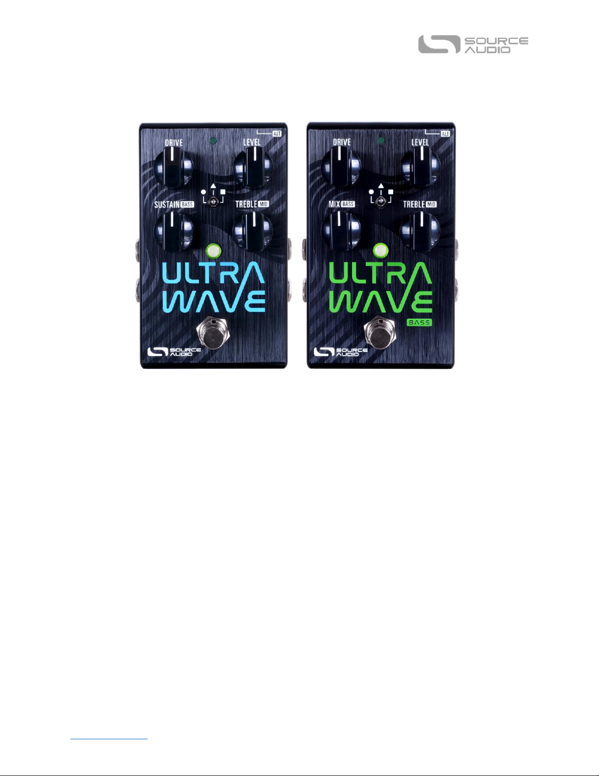
Table of Contents Ultrawave Multiband Processor User Guide
1
Ultrawave User Guide
Welcome
Thank you for purchasing the Source Audio Ultrawave Multiband Processor. The Ultrawave is the
first of its kind: a flexible multiband processing toolbox. Through the combination of band splitting,
exotic distortion curves, multi-band tremolo, compression, morphing, and flexible stereo processing,
the Ultrawave opens doors to a wide range of new sounds for guitar, bass, synth, and other musical
instrument applications. The Neuro Desktop and Mobile editors provide an intuitive graphical
environment to unlock the power of the Ultrawave, allowing users to create and share a growing
library of sounds.
At the core of the Ultrawave is multiband separation, distortion, and EQ. In the 1970s music
technologist Craig Anderton created a 4-band distortion tool. It was noted for lessening
intermodulation artifacts when playing complex chords, but the concept was left largely unexplored.
In 2007 Bob Chidlaw took the basics of multiband processing and added cutting-edge foldback
distortion curves, which were relatively unknown at the time. When implemented on a powerful
Analog Devices DSP chip, the Source Audio Multiwave Distortion pedal was born. The Ultrawave
starts where the Multiwave left off and leverages more than a decade of Source Audio know-how
and dramatic increases in DSP power. The Ultrawave is the ultimate expression of multiband
processing in a pedal. We hope you will enjoy our creation, and that it will provide years of
inspiration and fun.
Page 2

Table of Contents Ultrawave Multiband Processor User Guide
2
—The Source Audio Team
Table of Contents
1. Welcome
3. Feature Overview
4. Connecting the Pedal
4. Connections
8. Controls
10. Controls (Bass)
10. Theory of Operation
15. Distortion Types
15. Stereo Options & Signal Routing
18. Preset Storage & Recall
19. External Control
20. Expression Control
21. Neuro Desktop and Mobile Editors
21. Neuro Desktop Editor
24. Sound Editor
25. Master Controls
26. Morphing Controls
27. Compressor Module
28. Distortion Module
29. LFO Module
30. Graphic Equalizer Module
31. Single Tremolo/Envelope & Noise
Gate/Input Filter Modules
31. Envelope, Balance & Knob Assignment
Modules
33. The Neuro Mobile App — with New
Direct MIDI-USB Support
35. Neuro Hub
36. MIDI and USB
37. Specifications
38. Troubleshooting & FAQ
40. Warranty
41. Version History
Page 3

Table of Contents Ultrawave Multiband Processor User Guide
3
Feature Overview
37 Different Band-Splitting Options: Band Splitting options including single, 2, 3, 4, 8, and
10 bands. Each band splitting option includes several sub-sets with different band splitting
frequency points.
44 Different Distortion Types: Choose from distortion/overdrive/fuzz types that include
Tube, Diode, Foldback, Negative Flip Diode, Octave Up, and more.
Dual Channel Compressor/Expander: Compressor features Input Gain, Threshold, Ratio,
Attack, Release, and Output Gain controls with a detailed graphic monitor. Use the dual
channel capabilities to isolate compression to specific frequencies. Place the
compressor/expander before or after the overdrive module.
A Growing Library of Published Presets: For quick and easy access to a world of great
tones, try sampling sounds from a vast collection of published presets created by the Source
Audio team and the ever-growing Ultrawave Neuro Community.
Stereo Ins and Outs: Create two entirely different presets and run them in series, parallel or
run each to a separate output. Stereo options also apply to the Multiband Tremolo - use the
Channel 1/Channel 2 Sync options or the Phase Offset control to create stereo ping-pong,
tremolo effects.
Detailed LFO Controls: Use the LFO module to control the Ultrawave's Tremolo, Morphing
or Ring Mod features. Choose between a standard Sine Wave or use the Attack/Release
controls to create highly customized LFO shapes.
Sound Morphing: Change from one sound to another with an expression pedal, envelope
follower or LFO.
Extreme Tonal Control including an 8-band graphic equalizer, a 3-band parametric
equalizer, a configurable HPF & LPF, and an adjustable noise gate.
Assignable Knobs: Reassign all four of the Ultrawave's knobs to the parameters most useful
for making quick, on-stage changes. Save a different set of knob assignments for every
preset.
External Expression Pedal Control: Make simultaneous, on-the-fly changes of up to three
parameters with an external expression pedal.
6 Toggle Switch Accessible Presets: Quickly access up to 6 pedal presets with the
Ultrawave's toggle switch.
Page 4

Table of Contents Ultrawave Multiband Processor User Guide
4
MIDI Capable — Connect the Ultrawave to the Source Audio Neuro Hub or a USB-MIDI Host
and access up to 128 presets with MIDI Program Change (PC) messages. Control many of the
pedal’s parameters with MIDI Continuous Controller (CC) messages or assign LFO
modulation speed with MIDI Clock.
USB Port - Class compliant USB-MIDI allows the Ultrawave to work as a plug-and-play device
with recording software running on Mac and Windows. The USB port offers connectivity to
the Neuro Desktop Editor providing access to deep editing possibilities and pedal firmware
updates.
Compact Design – The durable, anodized aluminum housing has a small footprint and sturdy
hardware.
Universal Bypass™ – Select either analog buffered or relay based True Bypass.
Connecting the Pedal
Power
To power the unit, connect the included 9V DC center-negative power supply (at least 150mA
required) to the jack labeled DC 9V on the back panel.
Warning: Using a non-Source Audio supply, especially an unregulated supply, could damage the unit.
A power supply with insufficient current levels may also cause noise or other unpredictable behavior.
Please be very cautious when using 3rd-party power supplies and refer to the power supply
requirements in the Specifications section of this guide.
Connections
Guitar/Audio Connections
Using standard ¼” mono (TS) cables, connect your guitar, bass, or other instrument to the INPUT 1
jack and your amp (or the next audio device in the signal chain) to the OUTPUT 1 jack. If you have a
second amp, connect it to OUTPUT 2.
When the power and audio connections have been made, Ultrawave is ready for use.
Page 5

Table of Contents Ultrawave Multiband Processor User Guide
5
Input Side Connections
INPUT 1
INPUT 1 is the primary input for guitar, bass, or other instruments. It can also accept line-level inputs
and will work in your amp’s effect loop. Connect it to your instrument or other audio source using a
mono (TS) 1/4” cable. Details about the appropriate signal levels are available in the Specifications
section.
INPUT 2
Use the secondary audio input for stereo sources or as the data connection to your mobile device
when using the Neuro App.
• INPUT 2 as an Audio Input: The tip contact on INPUT 2 acts as a secondary input for guitar, bass,
or other instruments. Connect your instrument (or the previous effect in the signal chain) using
a mono (TS) ¼” cable. The Ultrawave will automatically configure itself for stereo audio input.
Other routing options are available using the Neuro App. For more information about stereo
routing, refer to the Stereo Operation section.
• INPUT 2 as a Neuro App Data Input: The ring contact on INPUT 2 acts as a data connection for the
Neuro Mobile App. The Neuro App sends data to the pedal using your mobile device’s
headphone jack. Connect it to your mobile device using the included stereo (TRS) 1/8” to 1/4”
cable. It can also accept daisy-chained Neuro data from another Neuro-compatible pedal in the
chain, provided that a TRS cable is used. The audio signal (if applicable) will be on the tip contact
of the plug, and the Neuro App data will be on the ring contact. This allows audio and Neuro
data to flow on the same cable.
Page 6
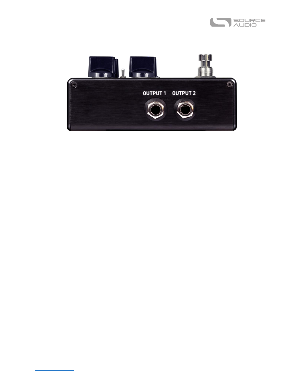
Table of Contents Ultrawave Multiband Processor User Guide
6
Output Side Connections
OUTPUT 1
This is the primary audio output. Connect it to your amplifier, recording interface, or the next device
in your effects signal chain using a mono (TS) ¼” cable.
OUTPUT 2
OUTPUT 2 can act either as an audio output or a daisy-chain data connection for the Neuro App.
• OUTPUT 2 as an Audio Output: The tip contact on OUTPUT 2 acts as the secondary audio output.
It carries an audio signal when the Ultrawave is configured with a signal routing that uses stereo
outputs. Connect it to your amplifier, recording interface, or the next device in your effects
signal chain using a mono (TS) ¼” cable.
• OUTPUT 2 as a Neuro App Data Daisy-Chain Output: The ring contact on OUTPUT 2 acts as a data
connection for the Neuro App, passing data from the Ultrawave to the next Source Audio effect
in your signal chain. You can daisy-chain the Neuro App data regardless of whether OUTPUT 2 is
configured to output audio or not. Connect OUTPUT 2 to the next device’s Neuro App Data input
(usually INPUT 2) using a stereo (TRS) 1/4” cable. The audio signal (if applicable) will be on the tip
contact of the plug, and the Neuro App data will be on the ring contact. This allows audio and
Neuro data to flow on the same cable.
Page 7
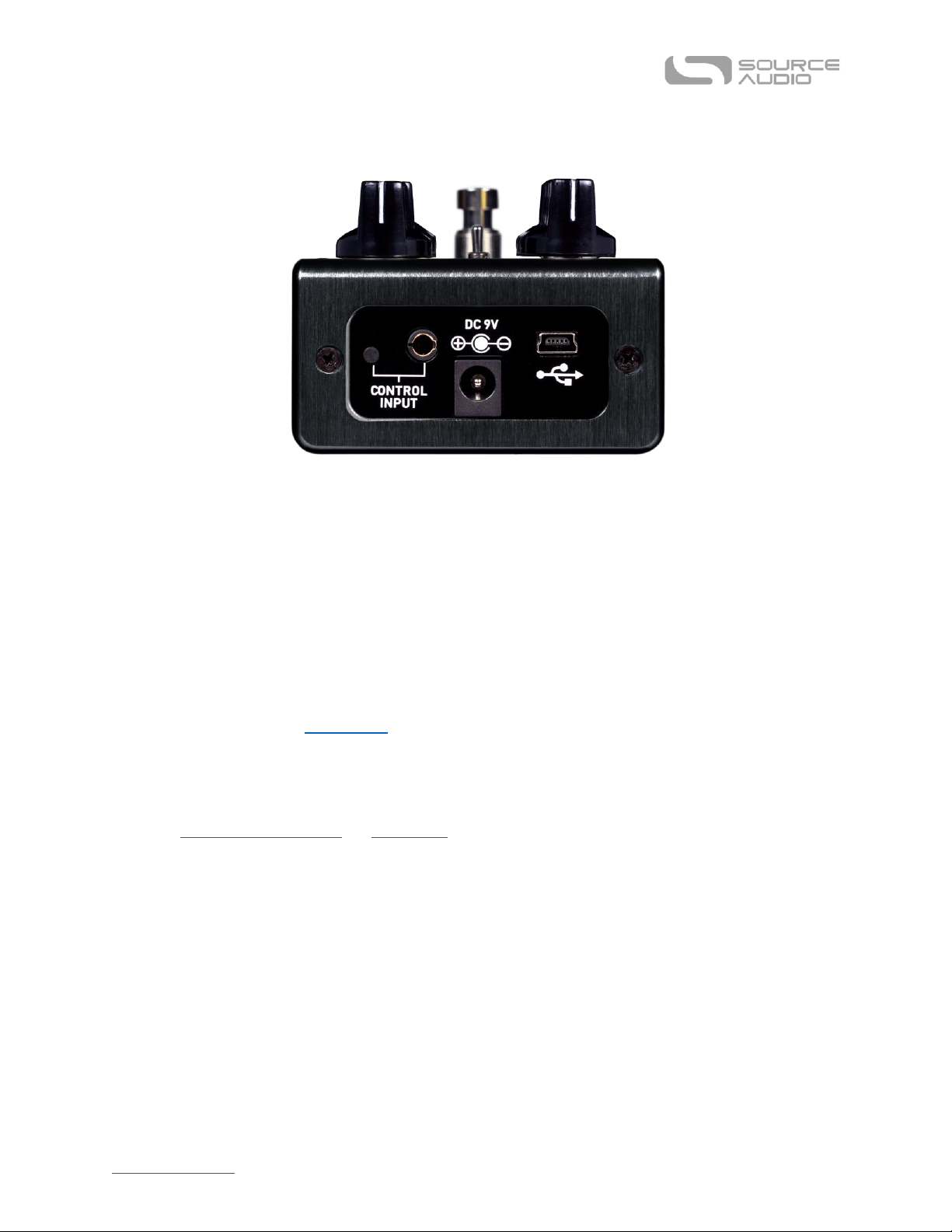
Table of Contents Ultrawave Multiband Processor User Guide
7
Power and Control Connections
DC 9V (Power)
Connect to the included 9 Volt DC power supply. If you would like to use a 3rd-party supply, the
power supply must be regulated at 9 Volts DC (direct current), able to source at least 150 mA
(milliamps) of current, and the plug should have a center-negative polarity.
USB
Connect your computer or mobile device (Windows or Mac) to the Ultrawave’s USB port (denoted by
the icon) using a standard USB mini-B cable. The Ultrawave is a class compliant USB device, meaning
that it does not require any custom drivers. For more information about the Ultrawave’s USB
capabilities, refer to the USB Section of the User’s Guide.
CONTROL INPUT
The 3.5 mm CONTROL INPUT port connects to external control devices such as the Source Audio Tap
Tempo Switch, Source Audio Dual Expression Pedal, and the Neuro Hub. For more information, refer
to the Expression Pedal Input and Neuro Hub sections of the User’s Guide.
Page 8
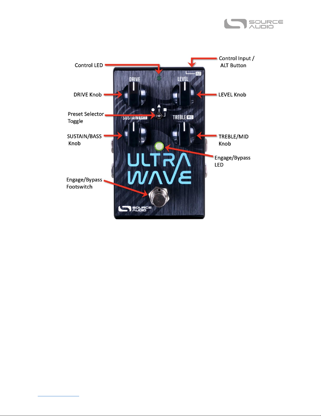
Table of Contents Ultrawave Multiband Processor User Guide
8
Controls
Note: The four top-level knob controls (Drive, Level, Sustain, and Treble) can be reassigned in the
Neuro Mobile App and Neuro Desktop Editor from a list of many possible parameters.
Footswitch
Click the footswitch to engage or bypass the pedal. Press and hold the footswitch down while the
pedal is bypassed to bank to Red LED (ALT) Mode for more presets.
Control Input / ALT Button
This small button located at the top of the pedal is used to enable or disable external control. It also
is used to control the ALT parameters on the surface of the pedal. Press and release the ALT button;
while the Control LED is flashing, turning the SUSTAIN or TREBLE knobs will access their alternate
parameters, Bass level and Mid level.
ON/OFF LED
The ON/OFF LED indicates whether the effect is bypassed or engaged. In ALT Mode, the LED
becomes red.
DRIVE Knob
Adjusts the distortion level. Turn clockwise for more distortion and saturation, or turn
counterclockwise for cleaner sounds.
Page 9

Table of Contents Ultrawave Multiband Processor User Guide
9
LEVEL Knob
Adjusts the overall output volume. Turn clockwise for more volume, or counterclockwise for less
volume. Note: Due to the varying nature of the presets and band-splitting options, the overall
output level may change for each preset, adjusting the range of this control. Because of this, there is
no hard-set “unity gain” point on the knob.
SUSTAIN/BASS Knob
Adjusts the sustain of the distortion by manipulating the input gain before the compressor. Turn
clockwise for more sustain and a bit more saturation. Turn counterclockwise for less sustain and a
more open sound/feel.
In ALT mode, this knob controls the amount of bass frequencies present in the outgoing signal. Turn
clockwise for more low end, and turn counterclockwise for less low end.
TREBLE/MID Knob
Controls how bright or mellow the overall effect is. Turn clockwise for a more top end bite, or turn
counterclockwise for a darker sound with attenuated high frequencies.
In ALT mode, this knob controls the amount of midrange present in the distortion. Turn clockwise for
a more warm, classic sound, and turn counterclockwise for a more scooped, modern sound.
Preset Selector Toggle
Use the Ultrawave’s three-position toggle switch and two preset banks to easily access six different
presets. First Preset Bank (indicated by the green center LED): default the center toggle switch
selects between three presets stored in the first bank of presets. Second Preset Bank (indicated by
the red center LED): Pressing the ALT button on the topside of the pedal opens access to the second
bank of presets. After pressing the ALT button, the small LED at the top of the pedal’s face will start
to blink, indicating that the second preset bank is accessible with the toggle switch. Upon moving the
toggle switch the center LED will turn red indicating the current preset is drawn from the second
bank.
Page 10
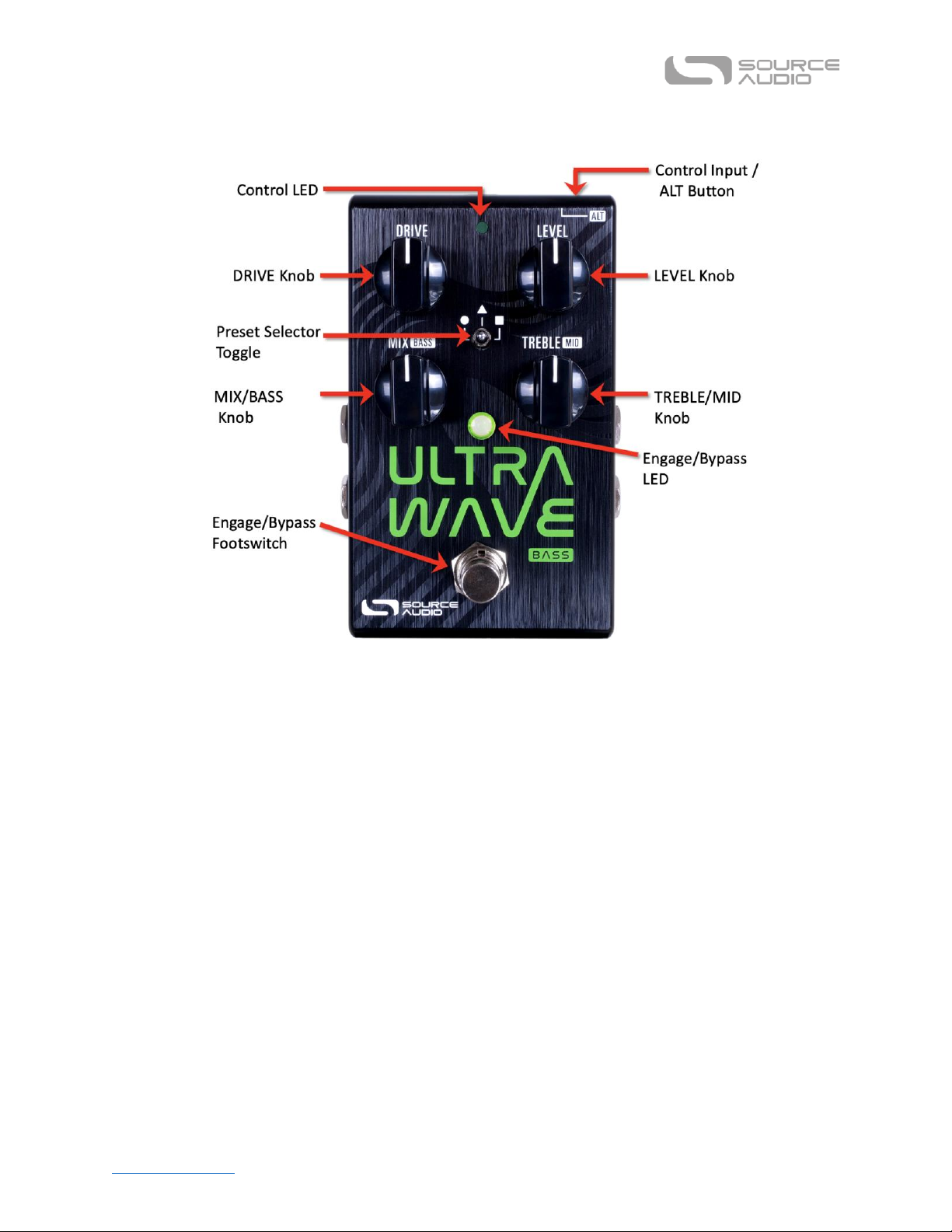
Table of Contents Ultrawave Multiband Processor User Guide
10
Controls (Bass)
Note: The four top-level knob controls (Drive, Level, Mix, and Treble) can be reassigned in the Neuro
Mobile App and Neuro Desktop Editor from a list of many possible parameters.
The only main difference in Controls on the Ultrawave Bass is that a MIX knob replaces the SUSTAIN
knob on the guitar version. The MIX control is a dry to wet crossfade control. Fully clockwise on the
knob is full “wet”, meaning no clean signal is present, only signal distorted or manipulated by the
Ultrawave will be heard. At noon, there is a 50/50 clean mix, and at fully counterclockwise, the
signal is fully clean (no distortion).
* * *
Theory of Operation
A graphic or parametric EQ is a simple and common form of multiband processor. In that case, the
signal is split into separate frequency bands, levels in each band are set, and then the signal is
recombined. By controlling the levels in each band, a wide variety of tones can be created. The
Ultrawave takes this basic concept of multiband processing to a much higher level in the following
ways:
• applying varying levels and types of distortion.
• applying optional tremolo and phase offsets to each band.
• applying compression before or after the multiband processing.
Page 11
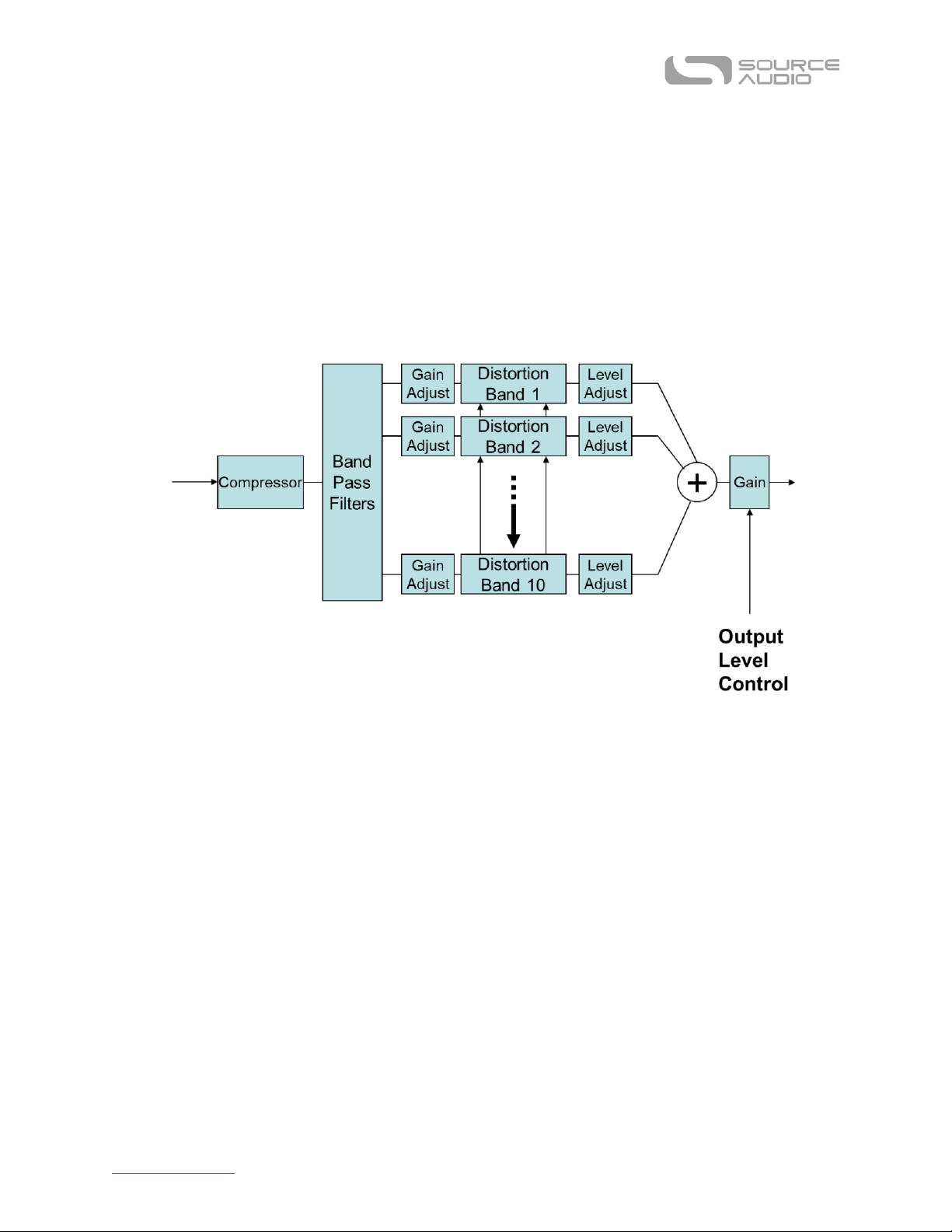
Table of Contents Ultrawave Multiband Processor User Guide
11
• applying EQ where necessary to shape the tone.
• allowing for a complete set of alternate states to be defined in the multiband processor and
then “morph’ between both states via LFO), envelope, or expression.
• creating 2 complete signal paths with routing options for parallel processing, cascading,
placement of the effect in 2 locations of a pedal board, and the creation of complex stereo
images.
Simplified Multiband Distortion Example
The diagram above shows the Ultrawave in a classic multiband distortion application. Following a
gain/compression stage, the signal is then split into ten separate bands. Each band then passes
through dedicated and separate level setting and distortion stages. Finally, the ten bands are
summed together to form the output signal. There are many interesting consequences of passing
the signal though the ten bands rather than a traditional single band distortion stage. Firstly, the
distortion tone is significantly more harmonically complex. Secondly, it is possible to play complex
chords with more clarity. This occurs because each guitar string tends to find its own path through
one of the ten bands and is not “stepped on” by the harmonics of a neighboring string. The net
result is a distortion sound palette that is not found on the thousands of common distortion pedals
that are on the market.
Page 12
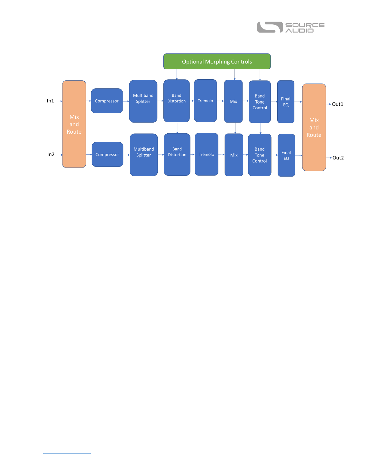
Table of Contents Ultrawave Multiband Processor User Guide
12
Ultrawave Signal Path
The diagram above is a functional representation of the signal path inside the Ultrawave. One should
note there are 2 separate signal paths to provide true stereo, stereo imaging, and other multichannel routing options. The multiband separation, distortion, and gain control lies in the center on
the path. Note that the multiband blocks plus EQ and filtering can be “morphed” between two
defined states via LFO, envelope or expression. For instance, one could create a clear octave up tone
in one state and then a highly distorted foldback tone in the second state. If used with an envelope,
a struck note would ring with a clear octave up tone, but then decay into highly distorted foldback
fuzz. This is one example on an infinite range of possible sound creation options. There are two
compressors in the Ultrawave, and they can be placed before or after the multiband processing.
Through use of EQ and routing options, it is possible to use the Ultrawave as a 2-band compressor.
Finally, it is possible to add phase offset tremolo to each band. Multiband tremolo adds yet another
innovative and interesting option to the Ultrawave multiband toolbox. The diagram below
summarizes the function of each block.
Page 13
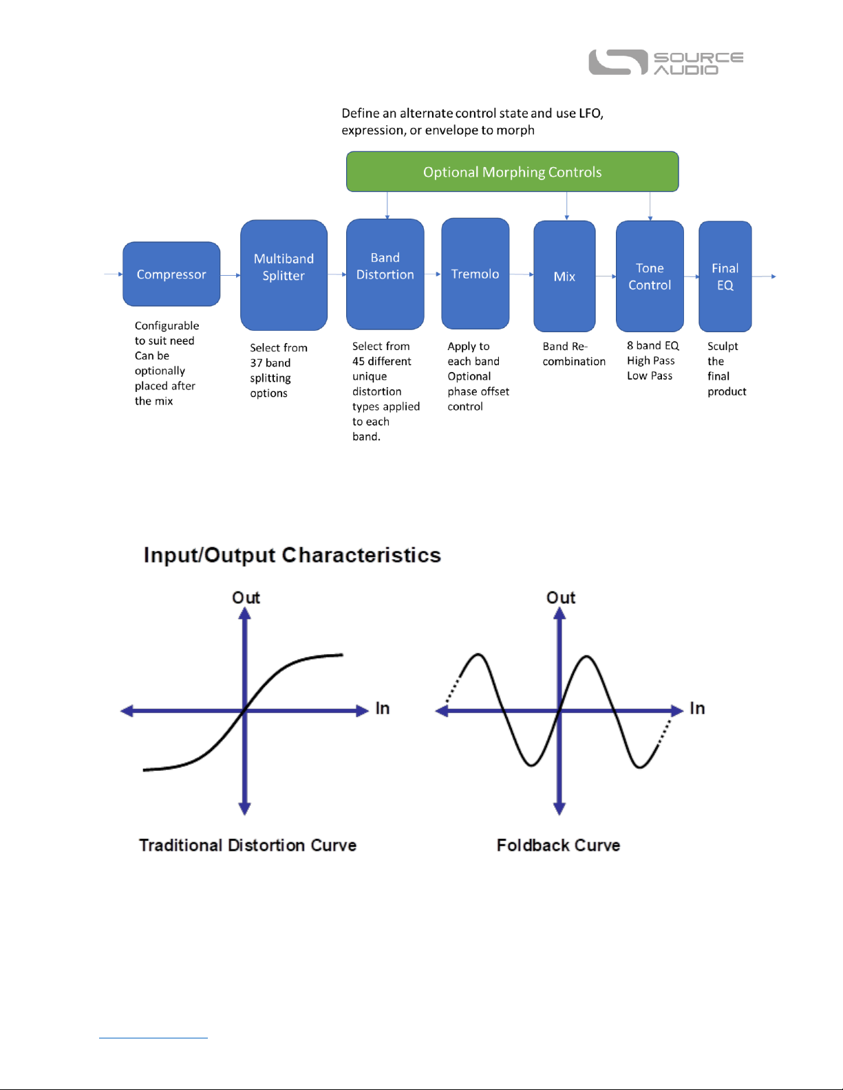
Table of Contents Ultrawave Multiband Processor User Guide
13
Foldback Distortion
Foldback distortion is one of the many distortion curve options on the Ultrawave. It is worth some
background because they are not commonly found in effect pedals. In traditional distortion, as the
input signal voltage rises, the output voltage also rises, but begins to level off and finally pins (or
clips) at a maximum value. With a foldback curve, for large enough values of the input, the output
will begin to decrease. With more extreme amounts of foldback, after decreasing for a while, the
Page 14

Table of Contents Ultrawave Multiband Processor User Guide
14
output can begin to increase again. Maximum foldback has many regions where the output
alternates between increasing and decreasing. These kinds of curves add a lot of high frequency
content to the output. It also can provide a lot of control over the sound, based on the level of the
input signal. With foldback, chords containing only octaves and fifths tend to sound best. Other
intervals can cause some strange, although not necessarily undesirable sounds.
Using a special shape of the distortion curve, strong second harmonics can be created, sounding like
a note an octave higher. Rolling off the guitar tone control or switching to the neck pickup will help
maximize the octave impression by attenuating the higher-order harmonics. Complex chords do not
typically work well for octave settings. The result is sensitive to the input signal level (as long as the
SUSTAIN and DRIVE controls are not set too high) and can give a sort of auto-wah effect.
A conventional distortion effect tends to turn the guitar signal into square waves. Playing harder
only makes the transition from negative clipping to positive clipping a little bit steeper. With the
foldback and octave algorithms found in the Ultrawave, a slightly higher input can have a radical
effect on the shape of the output signal.
Distortion Types
When using the Neuro Mobile App or Neuro Desktop Editor, you can select from a large list of
distortion types as you’re building a sound. Below is a guide to all the terms used in the Distortion
Type list, and how to differentiate between them. Essentially, the Ultrawave uses these sounds or
some combination of these sounds for each of the 44 distortion options.
For further reading and a visual representation of each unique distortion element, visit the Distortion
Appendix.
• Basic (Tube) Distortion - Similar to how Tubes feel and sound, gain goes from nearly linear to the
input signal, to sag, to compressed distortion based on input level.
• Hard Clip - like Op-Amp style hard clipping.
• Offset - like Asymmetrical clipping (for reference, a Boss SD-1 uses asymmetrical clipping compared
to a TS9 which uses symmetrical clipping in an otherwise similar circuit).
• Diode - Similar to LED Diode clipping.
• Gate - Any signal below the threshold is set to zero, and sustained signals will sputter out. Very
Velcro-like in nature.
• Absolute Value – Essentially, this is the “code equivalent” of the 2-transistor Superfuzz circuit that
causes an octave-up effect.
• Octave - Uses different tech for a smoother sounding octave, better for combining with other
elements like Foldback.
• Foldback - The classic, synth-like, overtone-rich effect from the original Multiwave. Derived from
modular synths. The distortion curve begins to collapse and turn back toward 0 when clipped.
Page 15

Table of Contents Ultrawave Multiband Processor User Guide
15
Stereo Operation & Signal Routing
The Ultrawave is flexible for many different uses due to its stereo INPUT and OUTPUT jacks. By
default, the Ultrawave auto-detects the cables connected to INPUTS and OUTPUTS 1 & 2 and engages
the appropriate Routing Mode. Stereo Routing can also be performed manually with the Neuro
Editors; select between “Mono In, Stereo Out” or “Stereo In, Stereo Out.”
Auto Routing Modes
There are four routing modes available when the Ultrawave is in its default Auto Detect mode. See
detailed descriptions of each Auto Detect mode in the sections below.
• Mono In, Mono Out
• Mono In, Stereo Out
• Stereo In, Stereo Out
• Stereo In, Mono Out
Mono In, Mono Out
This is the most common use case. Plugging the incoming signal into INPUT 1 with OUTPUT 1
connected to an amp (or the next device in the signal chain) produces a standard mono signal. Dual
processing effects are also mixed down to a single output.
Mono In, Stereo Out
This is a very common use case that allows you to create some nice stereo imaging from a single
mono instrument input or use your Ultrawave as a splitter to send your signal to two separate
outputs. When the unit is bypassed in this mode, it will automatically switch to Soft Bypass mode to
maintain the bypass signal on the Channel 2 output. When Ch. 1 and Ch. 2 are linked, the processing
will be the same for both channels. When they are unlinked, you can configure separate settings for
Channel 2.
Page 16

Table of Contents Ultrawave Multiband Processor User Guide
16
Stereo In, Stereo Out
This mode should be your default selection for Stereo In, Stereo Out applications. Stereo In, Stereo
Out allows you to continue your stereo chain of effects. When Ch. 1 and Ch. 2 are linked, the
processing will be the same for both channels. When they are unlinked, you can configure separate
settings for Channel 2.
Stereo In, Mono Out
This mode will accept stereo input on jacks INPUT 1 and 2. Inputs 1 and 2 are sent to Channel 1 and 2
respectively. When Ch. 1 and Ch. 2 are linked, the processing will be the same for both channels.
When they are unlinked, you can configure separate settings for Channel 2. The outputs of the
Channel 1 and Channel 2 equalizers are mixed together and sent to OUTPUT 1.
Page 17

Table of Contents Ultrawave Multiband Processor User Guide
17
Additional Routing Modes
The Ultrawave supports two additional routing modes, Cascade Ch.1 -> Ch. 2 and Mono -> Stereo ->
Mono available in the Neuro Mobile App and the Neuro Desktop Editor. View the routing modes
below to find out how you can configure the Ultrawave’s inputs, outputs and dual channels using a
Neuro connection.
Cascade Ch. 1 -> Ch. 2
This routing mode allows you to run both channels in series, meaning Channel 1 will cascade into
Channel 2. This is a very useful routing mode in terms of tone shaping and drive-stacking. When Ch.
1 and Ch. 2 are linked, the processing will be the same for both channels. When they are unlinked,
you can configure separate parameters for Channel 2.
Page 18

Table of Contents Ultrawave Multiband Processor User Guide
18
Mono -> Stereo -> Mono
This routing mode also allows for both channels to be run at once, but in this case, they are being run
in parallel. The Channel Balance control in the Neuro sound editor comes in handy in this routing
mode, as it controls the relative mix levels of each channel. When Ch. 1 and Ch. 2 are linked, the
processing will be the same for both channels. When they are unlinked, you can configure separate
parameters for Channel 2.
Preset Storage and Recall
User Presets store all user-editable parameters. This includes the knob positions, parameter settings,
frequencies, routing options, external control, and the full list of Neuro/MIDI-accessible parameters.
Included in every preset are settings for either channel (Channel 1 [Mono] or Channel 2). After a
preset is recalled, you can always tweak the top-level controls in a performance situation by turning
the knob. The knob parameter will then “jump” to the current knob position as it is rotated.
Recalling Presets
The first six User Presets are accessible via the onboard hardware or with an external footswitch in
the following ways:
1. Move the toggle switch to left, center, or right to access presets #1-3.
2. Press the ALT button, then while the Control LED is flashing, move the toggle switch to access
presets #4-6, or press + hold the footswitch when the pedal is OFF for 5 seconds (or 2 second in
“Quick Change” mode) to access the Red LED (presets #4-6).
Recalling MIDI Presets
All 128 available User Presets are accessible with an external MIDI controller. MIDI controllers can be
connected via USB port at the top of the pedal, or through a Neuro Hub, which connected to the
CONTROL INPUT at the top of the pedal. All 128 User Presets can be recalled with the corresponding
Page 19

Table of Contents Ultrawave Multiband Processor User Guide
19
MIDI program change (PC) messages, or via continuous controller (CC) messages when accessing the
pedal’s internal presets via the Neuro Hub.
Note: When recalling presets via MIDI PC messages, you may wish to queue up your preset with
effect bypassed. To do this, simply engage the preset, bypass it with the footswitch, then re-save the
preset normally. When recalled, the pedal will load the saved user settings, but the effects will be
bypassed until you engage the pedal.
Copying a Preset to a New Location Using the Neuro App
Using the BURN and SAVE AS commands in Neuro Mobile or Desktop Editors, it is possible to copy
presets to any location in memory.
Clearing all Presets
All 128 User Presets can be erased using the Factory Reset procedure. Warning: The Factory Reset
procedure resets the entire pedal back to the state in which it was originally shipped – this includes
all global settings and User Presets. A Factory Reset will not erase any firmware updates.
External Control
Plug an expression pedal, an external footswitch, the Source Audio Tap Tempo Switch, or the Source
Audio Hot Hand 3 Universal Wireless Controller into the Ultrawave’s CONTROL INPUT jack and access
an array of external functionality and expression control.
External Switch
External switches can be used for several different control options. They provide an easy way to
remotely swap channels, tap the LFO tempo, and more. The Ultrawave is compatible with the Source
Audio Tap Tempo Switch.
External Switch Options
There are three main ways the Control Input port is utilized. Below are the possible used for the
Control Input port. Please note that External Switch Options is a global hardware setting.
Page 20

Table of Contents Ultrawave Multiband Processor User Guide
20
Neuro Hub: This configures the Control Input port to receive MIDI code signals from the Neuro Hub,
allowing the pedal to be added to Hub Scenes (which are controlled by PC messages) and allowing for
MIDI CC (Continuous Controller) control.
Expression: Using the Source Audio Dual Expression pedal or a third-party expression pedal
connected to the Neuro Hub, it is possible to map up to three parameters to be controlled via
expression.
Tap Tempo: Connect a Source Audio Tap Tempo switch to be able to tap in the speed of the
Ultrawave’s LFO. The LFO can be set to control single tremolo, the multiband tremolo, morphing, or
a combination of those elements.
External Switches (1/8” TRRS Connection)
The Source Audio Tap Tempo footswitch can also be connected to the CONTROL IN jack using a
3.5mm (1/8 inch) cable. If you wish to use this function, you must enable the function globally with
the “Use Control Input for External Switch” option in the Hardware Options section of the Neuro
Desktop Editor.
Source Audio Tap Tempo footswitches can be purchased directly from the Reverb.com Official Source
Audio Online Store.
Expression Control
Use a Source Audio Dual Expression pedal to control up to three different parameters on the
Ultrawave per preset. Parameters include Drive level, Output Level, Treble, Bass, Mid Control, Noise
Gate Enable, and many more.
Connecting the Expression Pedal
Connect a Source Audio Dual Expression pedal using a 3.5mm TRRS cable from the EXP pedal’s
Sensor Output to the Ultrawave’s CONTROL INPUT port on the pedal’s top panel. Press the CONTROL
INPUT button to enable External Control.
If you are not getting the desired results from your expression pedal setup, go to the Hardware
Options section of the Neuro software. You’ll need to select “Neuro Hub/Expression” under “Control
Input Option”, and you may also need to calibrate your expression pedal. For more details, visit
Hardware Options.
Page 21

Table of Contents Ultrawave Multiband Processor User Guide
21
Mapping Parameters
The quickest way to map parameters to your expression pedal is by connecting your Ultrawave to the
Neuro App or Neuro Desktop Editor. The Expression Control section is at the bottom of the
Ultrawave’s Sound Editor. Download the Neuro Desktop Editor and go to Devices > Show Offline
Device Editor > Ultrawave to view the full list of expressible parameters.
MIDI
The Ultrawave can also receive expression signals over MIDI. To do this, you would need a MIDI
controller that has an expression input, and which is also compatible with the Ultrawave (this will be
most MIDI controllers). Connect your compatible expression pedal to your MIDI controller, and your
MIDI controller to your Ultrawave. You can also achieve this with the Neuro Hub.
Neuro Desktop and Mobile Editors
Like all pedals in the Source Audio One Series line, the Ultrawave Multiband Processor features
access to more precise editing parameters, preset sharing, and added functionality via the Neuro
Desktop Editor and Mobile App. The Neuro Desktop Editor is available as a free download for Mac or
Windows on the Editors & Firmware page of the Source Audio website.
The Neuro Desktop Editor
The Neuro Desktop Editor is an excellent tool for creating and organizing highly customized presets
for your Ultrawave Multiband Processor. The Desktop offers an advanced cataloging system for
naming and storing Ultrawave presets. The Desktop is also a tool for installing the latest updates to
your Ultrawave’s firmware.
Downloading and Connecting the Neuro Desktop Editor
The Neuro Desktop Editor is a free download for Mac and Windows PCs. To download the Neuro
Desktop, go to the Source Audio Editors & Firmware page. In the Software tab select the appropriate
file (you have a choice between the Mac and Windows versions) and download it.
Page 22

Table of Contents Ultrawave Multiband Processor User Guide
22
After the download process, connect your Ultrawave with a USB Type A male to mini type B male
data cable (must be data-capable, not solely a charger cable). Connect the cable from the mini USB
port on the pedal to the USB port on your computer. Once you’ve made the connection a blue box
will appear in the Connections field indicating that the Ultrawave is ready to be edited.
If a new firmware update is available, the Firmware Update icon (the arrow icon) will be framed in
yellow. When you click the arrow icon, you will be instructed on the updating procedure.
Occasionally, a fresh download of the Neuro Desktop Editor will be required to access future
firmware updates, and it is always a good idea to check the Source Audio Editors & Firmware page to
see if there is a newer version of the editor available for download.
Neuro Desktop Editor User Interface
The Neuro Desktop’s user interface features three primary sections: Connections, Sound Editor, and
Presets.
Connections
The Connections section is located on the left side of the Neuro Desktop Editor. This field displays all
connected One Series pedals and the Neuro Hub. Each connected pedal offers the three options
listed below, from left to right:
Page 23

Table of Contents Ultrawave Multiband Processor User Guide
23
• Firmware Updates: The arrow icon checks for any recent firmware updates to the connected
pedal. If an update is available, the software will provide instructions on how to proceed.
• Hardware Options: The gear icon opens the Hardware Options window. Each Source Audio
pedal has its own set of global hardware settings. The attached pedal will retain all hardware
option edits until either the option is changed, or a Factory Reset is performed.
• Open Editing Interface: The wrench icon opens the Ultrawave’s Sound Editor, revealing a
deep set of editing controls for creating custom presets.
Hardware Options
Clicking the gear icon in the Ultrawave Multiband Processor’ Connections window opens the
Hardware Options menu (see the graphic below). Use the Hardware Options window to choose your
pedal’s global hardware settings.
The Ultrawave’s Hardware Options include the following:
• Preset/WYSIWYG Mode: Selects between Preset (all parameters are saved & recalled) and
WYSIWYG (the pedal’s physical knob positions override where they are set in the preset)
modes.
Page 24

Table of Contents Ultrawave Multiband Processor User Guide
24
• Hardware Bypass Mode: Selects between True or Buffered Bypass.
• MIDI Channel: Selects the pedal’s MIDI channel (1 through 16).
• Control Input Option: This dropdown menu assigns the control function of the external
switch connected to the CONTROL INPUT.
• Power Up State: Selects between engaging or bypassing the effect upon the initial power up
of the pedal.
• Default Routing Option: Sets the default I/O signal routing mode. Descriptions of the
available routing modes are available in the Stereo Operation & Signal Routing section of this
manual.
• Quick Bank Switch Using Footswitch (2 Seconds): Enabling this setting allows you to bank to
and from the secondary (red LED) bank of presets by pressing + holding down the footswitch
for 2 seconds instead of 5 seconds.
• USB-MIDI Skip Power Check (for use with USB-MIDI Hosts): The Ultrawave can receive MIDI
PC messages via the pedal's USB port. It requires MIDI DAW software or a MIDI host device
with USB. The Ultrawave should respond to most devices, but some don't generate enough
power for the Ultrawave to recognize them as a MIDI host (the MIDI Baby and qCONNECT
from Disaster Area Designs are two examples). If your Ultrawave is not responding to your
MIDI host device, try checking this box.
• Pedal Input & Control Input Calibration (accessible via the Show Expression Pedal
Calibration dropdown controls): In some cases, it might be necessary to adjust the
calibration range of an expression pedal to get the desired pedal response when using
expression control either through the Neuro Hub, a direct connection to the Source Audio
Dual Expression Pedal, or a 3rd-party pedal. To perform the calibration process, connect the
pedal and press the “Calibrate” button. Then rock the pedal back and forth to set the
minimum value and the range. When complete, press the “Stop and Set” button to retain the
new calibration values. Or press “Reset” to return to the default values.
Sound Editor
Upon clicking the wrench icon in the Connections section, the Ultrawave Multiband Processor’s
Sound Editor interface appears in a tab in the center panel. This is where all of the sound editing
work takes place.
The Sound Editor is broken into several sub-sections, each containing a unique variation of virtual
knobs and dropdown menus. The following is an in-depth explanation of each Sound Editor subsection.
Page 25

Table of Contents Ultrawave Multiband Processor User Guide
25
Master Controls
Link: The Ultrawave’s two discrete channels are linked by default in the preset editor to create one
master channel, for those presets that really only need one channel. De-select “Link” to access and
edit Channel 2.
Copy: When Ch. 1 and Ch. 2 are unlinked, the Copy arrows allow you to copy settings from Channel 1
to Channel 2, or from Channel 2 to Channel 1. The channel that is highlighted is the channel you are
currently editing. Use the arrows to select the target channel.
Routing Option: The Ultrawave utilizes stereo inputs and outputs, so the Routing Option selects how
you want them to be configured in conjunction with the 2 channels. You can also choose to run both
channels in parallel in mono, and even cascade Channel 1 into Channel 2 for more tonal complexity
and possibility. See the Stereo Operation & Signal Routing section for a detailed explanation of each
routing option.
On/Off State: This lets you toggle whether the effect is ON or bypassed and can be saved as a part of
the preset for easy recall.
Page 26

Table of Contents Ultrawave Multiband Processor User Guide
26
Drive: Sets the master drive level per channel, or for both channels simultaneously when this control
is Linked.
Level: Sets the master output volume per channel, or for both channels simultaneously when this
control is Linked.
Bass: Adjusts the overall low end per channel. The frequency value in Hz can be adjusted by clicking
within the readout box and dragging up or down.
Mid: Adjusts the overall mid frequency level per channel. The frequency value in Hz can be adjusted
by clicking within the readout box and dragging up or down.
Treble: Adjusts the overall top end per channel, or for both channels simultaneously when this
control is Linked. The frequency value in Hz can be adjusted by clicking within the readout box and
dragging up or down.
Mix: Adjusts the amount of clean mix blended in with the signal. Fully counterclockwise is
completely clean or “dry”, fully clockwise is completely distorted.
Morphing Controls
Morphing is a unique part of the Ultrawave feature set. It allows you to seamlessly change between
two separate sets of user-defined parameters, using the Ultrawave’s LFO, Envelope, or an external
source (see Expression Control). Morphing can be applied to both the Disortion Module and the
Graphic Equalizer module. When morphing is enabled, a second set of parameters will appear in
yellow, where you can define your morph to (yellow) voice and your morph from (blue) voice.
Morph: When morphing is turned on for any given parameter set, the Morph knob adjusts how
much morphing is applied. Fully counterclockwise is no morphing, and fully clockwise is maximum
amount of morphing.
Env->Morph: Adjusts the intensity at which the envelope applies to morphing.
LFO Depth: Adjusts the depth of the low-frequency oscillator used when morphing.
Page 27

Table of Contents Ultrawave Multiband Processor User Guide
27
Compressor Module
The compressor can be switched “on” or “off per preset and per channel.
Mode: Toggles between a compressor, which sustains and reduces the dynamic range of your input
signal, and an expander, which increases the dynamic range of your input signal, and in extreme
cases, softens the attack. In expander mode, signals below the threshold get softer; if attack time is
very slow, the expander generates a slowly rising signal.
Location: Toggles between putting the compressor before or after the multiband processing. PreDistortion is the traditional choice, while Post-Distortion produces a more drastic overall effect.
Input Gain: Adjusts the level of gain sent to the compressor. Increase for heightened sustain.
Threshold: Adjusts the decibel (dB) level at which compression is applied. A lower threshold means
that compression is applied at lower signal levels, meaning that less pick attack is needed to trigger
the compression. This point is called the “knee”. Any signal lower than the knee will not be
compressed, and any signal with a level higher than the knee will be compressed.
Ratio: Adjusts the severity of the compression applied to your signal. As you increase this knob, you
will see the line begin to flatten at the knee.
Attack: Adjusts how quickly the compression is applied to your signal after playing a note. For some
distortion mappings there may be a substantial transient at the attack; this can be suppressed with a
very fast attack in compressor mode.
Release: Adjusts how quickly the compression “lets go” of your signal after it has been applied.
Output Gain: Adjusts the level of gain after the compressor. Increase for heightened overall output.
In Pre-Distortion mode, this can help to drive the distortions even harder.
Mix: Acts as a clean blend between the dry and compressed signal. Fully counterclockwise is
completely clean—no compression. Fully clockwise is 100% compressed. Mixing dry signal back into
your compressed tone is what is known as “parallel compression”, and is often utilized in studios.
Soft Knee Width: When your signal approaches the point of compression at the threshold, the
transition can often sound abrupt. Soft Knee Width adds a smoothness to the knee to ease the
transition into compression, with higher values creating an increasingly more subtle feel.
Page 28

Table of Contents Ultrawave Multiband Processor User Guide
28
Distortion Module
The distortion can be switched on or off per preset and per channel. This means you can use the
Master Controls, Compressor, and EQ as standalone modules without distortion.
Band-Splitting: The Ultrawave contains 37 different band-splitting options. The most “traditional”
multiwave distortion sounds use 10-band distortion, which splits your signal into 10 separate
frequency bands and distorts them separately, creating rich, synth-like overtones. In addition to the
10-band splitter, you can select between multiple layouts of 2, 3, 4, 8, and 10 bands, each with
several different options to match different instrument EQs. There is also a single-band (no split)
option for more traditional distortion and fuzz tones.
Clean Option: When “Distortion Type” is set to “0. Clean”, you can select whether your clean signal
comes from the distortion input (default) or out from one of the bands, for a very specific set of
frequencies. This can be useful if you’re trying to compress a certain range of your signal.
Morph: When “Morph” is enabled, you can choose a second set of parameters in the distortion block
to morph between, using the onboard Envelope, LFO, or an expression pedal.
This set of values will be represented in yellow, in contrast with your initial set of parameters, which
are blue. This includes distortion type and individual band levels and gains.
Distortion Type: There are 44 different distortion types onboard, ranging from traditional styles of
distortion found in other gear, to experimental foldbacks only our scientist, Bob Chidlaw, could’ve
dreamed up. For more information about the distortion types included in the Ultrawave, see
Distortion Types.
Page 29

Table of Contents Ultrawave Multiband Processor User Guide
29
Multi-Band Drive Shape: Since each band is distorted separately, we’ve given you fine-tuned control
over each band’s drive and output levels. This dropdown contains presets we’ve created, if you’d
rather not mess with individual levels.
Drive, Level, and Midpoint Adj: When using Morphing, the parameters are being morphed between,
not a simple audio crossfade. Because of this, drive and output levels of each parameter set need to
be defined. Midpoint Adj is an optional gain boost (or cut) for the midpoint of the morphing, which
can often cause volume discrepancies.
Multi-band Tremolo
In addition to applying distortion to each band, the Ultrawave also allows for the application of
tremolo (manipulation of amplitude) to each band.
Mode: Much like the compressor, the multi-trem can be applied either pre-distortion or postdistortion. We’ve made post-distortion the default for a more pronounced sound.
Depth: Adjusts the overall depth of the multiband tremolo effect.
Band Phase Offsets: All bands are controlled by the same master LFO, but the tremolo of each band
can be set to a different phase (starting point) on that LFO waveform. Since the possibilities are near
infinite, we have created a drop-down menu for quick access to a selection of pre-set phase offset
patterns.
LFO Module
The LFO utilized by the Ultrawave's multi-tremolo can be either a sine wave or a user-defined
"Attack/Release" wave. (The single tremolo uses a standard sine wave only.)
The LFO wave diagram is interactive and it dynamically changes when the Attack, Release, Shape,
and On Time knobs are adjusted. Note: In Sine Waveform mode, the Attack, Release, Shape, and On
Time knobs have no effect.
Attack is the steepness of the upward slope of the wave.
Release is the steepness of the downward slope of the wave.
Shape adds sine-like curvature to the slopes when counterclockwise, or triangle/square-like rigidity
when clockwise.
On Time increases the time the LFO is sustained at its peak value in each cycle
Page 30

Table of Contents Ultrawave Multiband Processor User Guide
30
Rate controls the speed of the LFO.
Env->Rate sets the acceleration / deceleration of the amplitude-controlled LFO. At noon, no
acceleration or deceleration is applied. Before noon on the knob, you get LFO acceleration as the
envelope closes, and past noon you get LFO deceleration as the envelope closes.
Enabling Ring Mod inreased the LFO speed into pitch territory, producing a ring modulator effect.
The rate of the LFO can be input manually using the Tempo module, either by tapping or clicking the
Tap Tempo button and selecting a beat division in the dropdown underneath it, or by inputting a Hz
or BPM value in the field beneath the beat division dropdown.
The Ultrawave can also be synced to an external MIDI Clock per preset, by enabling the “Sync to MIDI
Clock” button.
The LFO in Channel 2 can be synced to Channel 1 in any of the configurations listed in the “Ch. 1 : Ch.
2 Sync” dropdown menu, and the phase offset of Channel 2 relative to Channel 1 can be set in the
knob directly beneath it.
Graphic Equalizer Module
The Graphic EQ can be switched on or off per preset and per channel.
For ultimate tone-sculpting, we’ve included a morphable 8-band graphic equalizer and two
morphable filters. Much like the Distortion module, the Graphic EQ’s parameters can be morphed
between a second set of parameters that will appear when enabling the “Morph” button.
The filters, represented as sliders, are very powerful and will help you make fine tweaks to achieve
the precise tone you’re searching for.
High Pass Filter: An important equalizing tool is a high-pass shelving filter. By clicking in the box and
dragging up or down, you can adjust the frequency point at which the filter begins cutting lower
frequencies below that point. The higher the Hz value, the more dramatic the bass cut will sound.
Low Pass Filter: An equally important equalizing tool, known as the low-pass filter, helps to
attenuate high frequencies. If you’re getting unwanted top-end treble, you can shelve it off by
adjusting the frequency point of this low-pass filter by clicking in the field and dragging it up or down.
Page 31

Table of Contents Ultrawave Multiband Processor User Guide
31
Single Tremolo/Envelope & Noise Gate/Input Filter Modules
The Ultrawave is also packed with a single tremolo for more conventional tremolo sounds. This
single tremolo utilizes the sine wave and is controlled by the same Rate control in the LFO module.
The depth is broken up into Pre-Distortion and Post-Distortion control.
Envelope To Volume switches on the amplitude-controlled envelope when set to either PreDistortion or Post-Distortion.
Gate Threshold adjusts the Ultrawave’s internal noise gate. Many of the distortion types are already
gated, but you may desire to turn up the gate even higher to eliminate noise, hum, and feedback.
Input High Pass controls a configurable high pass filter applied to your input signal if you need to
attenuate lower frequencies before the signal is processed by the Ultrawave. The default is 10.0Hz,
which effectively removes the high pass filter, since it is below the threshold of the human ear.
Envelope Generator, Balance, and Knob Assignment Modules
Envelope Generator: The Ultrawave’s envelope comes with two simple controls and an input
selector for assigning it to either Input 1 or Input 2. Input Gain acts like a sensitivity control; the
higher the Input Gain, the lighter you need to play in order to open the envelope. Attack adjusts
how quickly the envelope reacts.
The Balance control is a Channel 1/2 mixer. When the knob is at noon, there is an even 50/50
balance between channels 1 and 2. When the knob is fully counterclockwise, you will only hear
channel 1. When the knob is fully clockwise, you will only hear channel 2.
Env->Balance controls the intensity at which the Envelope affects the channel Balance control.
LFO->Balance controls the intensity at which the LFO affects the channel Balance control.
Page 32

Table of Contents Ultrawave Multiband Processor User Guide
32
Knob Assignment: Many Source Audio pedals contain knob assignment (or re-assignment) controls
for top-level flexibility. The Ultrawave is no different. Each of the top four knobs can be reassigned
in this module from a list of parameters. The knob assignments are set and stored on a preset-bypreset rather than global basis for ultimate flexibility of control.
Link: Clicking Link next to each knob will allow that parameter to be controlled in both channels
simulatneously.
External Control
Control up to three parameters with a Source Audio Dual Expression Pedal, Tap Tempo Switch, or
third-party expression controller via the Neuro Hub or USB-MIDI. Use the dropdown menus in the
External Control block to select the expression device (Control Source) and controlled parameter
(Control Option). Use the Min and Max fields to set the depth of the expression sweep.
Presets
The Presets section is located on the right side of the Neuro Desktop interface. There you will find a
list of all the presets and empty preset positions available in your Ultrawave. The Presets section is
also where you Save, Import, and Export presets. The buttons located at the top of the Presets field
perform the functions listed below:
Page 33

Table of Contents Ultrawave Multiband Processor User Guide
33
• Save Button: If you have made edits to a pre-existing preset, use the Save button to update
the preset without changing its name or preset position.
• Save As Button: After creating a new preset hit the Save As button and you will be prompted
to name it and select the preset or Effect Selector position to which it will be saved.
• Import Button: Use the Import button to upload saved .pre files to your Neuro Desktop
Editor. Upon clicking the Import button, you will be asked to find the .pre file. Simply go to
your Neuro presets folder, select file, and upload.
• Export Button: Use the Export button to save a preset on your computer or share it with
other musicians. Presets are saved as .pre files and stored anywhere on your computer (we
recommend creating a dedicated folder to store your presets). After creating a preset, hit
the Export button - a window will pop up, asking you to name, tag, and select a location for
the preset. After the preset is saved, the .pre file can be shared via email or any common file
sharing method.
• Refresh Button: Hit the Refresh button to restore the Neuro Desktop edits to the state
immediately after your last save procedure.
• Hardware Presets: This is where all of your pedal presets are listed. Use the Save As button
to select where you would like to store an edited preset—you can choose from any of the
128 preset positions. You may also right click on any preset slot to erase it. Any preset with
an asterisk * means that there are unsaved changes to that preset.
• Save To Cloud: Hit the Save To Cloud button to share your preset with the Neuro Community
so that anybody with a Neuro account can audition, like, and download your preset.
The Neuro Mobile App — with New Direct MIDI-USB Support
Page 34

Table of Contents Ultrawave Multiband Processor User Guide
34
Like all Source Audio One Series pedals, the Ultrawave is fully supported in the Neuro Mobile app.
The Neuro Mobile app is available for iOS and Android devices and allows access to all of the preset
parameters and hardware options described in the Neuro Desktop editor section above.
Connecting to the Neuro Mobile App (USB-MIDI)
The Ultrawave is the second Source Audio pedal after the EQ2 to add two-way communication with
the Neuro Mobile app using MIDI over USB. This means that any changes made on the pedal are
immediately reflected in the app and that the app always reflects the actual current state of all the
pedal's parameters, rather than the one-way audio connection to Input 2, where the Neuro App is
only able to send signals and not receive any. To connect the Ultrawave to the mobile device you will
need the proper cable adapters.
• iOS Devices – Any iOS device with a lightning connector is supported. A “Lightning to USB
Camera Adapter” is required. Connect the adapter to the USB A/B-mini cable that was
included with your Ultrawave.
• Android Devices – Android devices may have either USB-micro or USB-C connectors that will
support MIDI over USB communication with the Ultrawave. You will need the appropriate
USB B/C (male) to USB A (female) adapter to use with the included USB A/B-mini cable. Note
that the USB B-micro to USB A adapter is sometimes called an OTG (On-The-Go) adapter.
Connecting to the Neuro Mobile App (headphone jack)
The Ultrawave also supports one-way communication between a mobile device and the pedal using
the included TRS ¼” to 1⁄8” cable. Connect the cable to the headphone jack (or headphone to
Lightning dongle for Apple devices) of your mobile device and Input 2 of the Ultrawave. The cable is
a TRS (stereo) connector that uses the “Right” channel to send data over audio signals to the pedal.
When using the headphone jack connection, we recommend using the Volume Calibration features
in the Neuro Mobile app to configure the audio output for the most reliable communication between
the mobile device and pedal.
Page 35
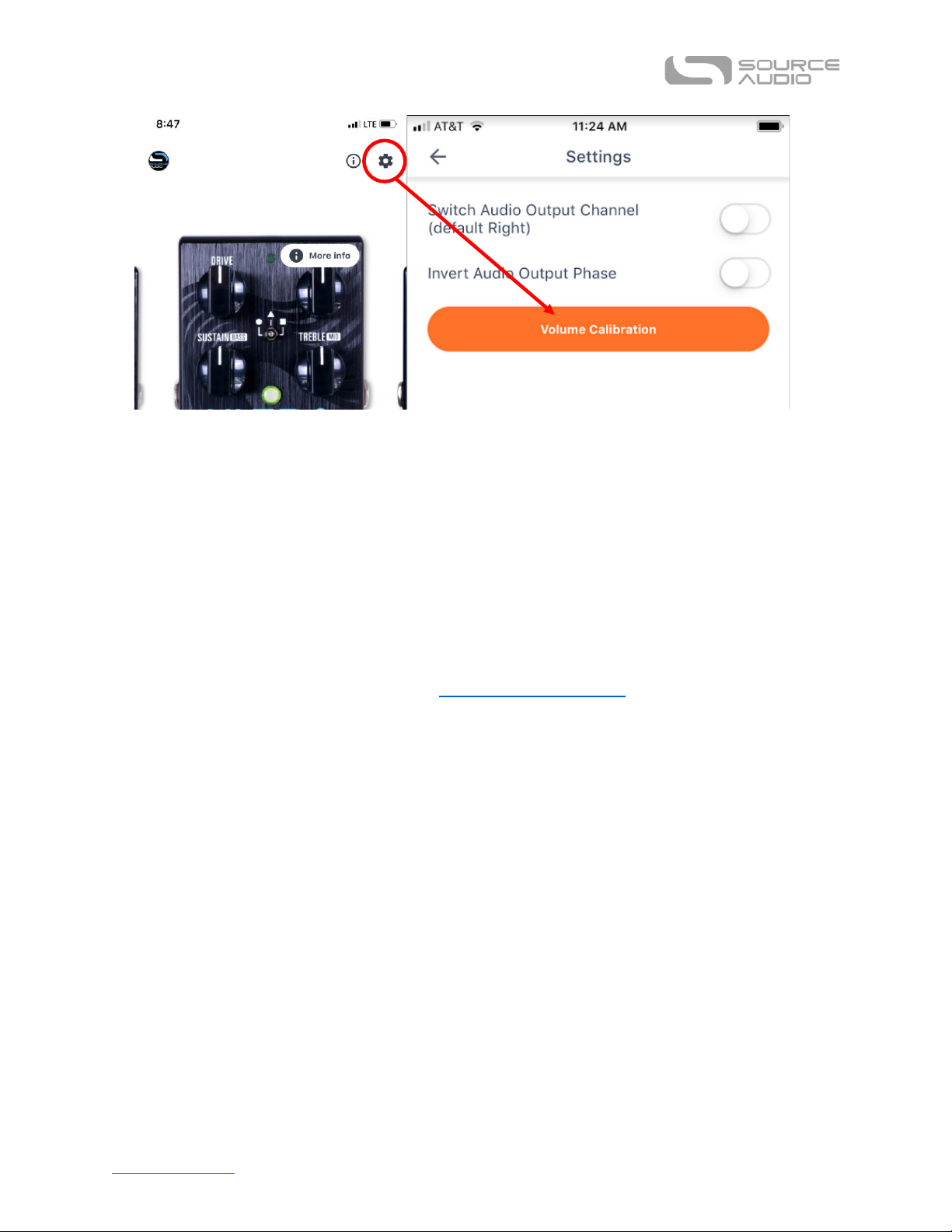
Table of Contents Ultrawave Multiband Processor User Guide
35
Neuro Hub
The Source Audio Neuro Hub (sold separately) unites Source Audio pedals from the Soundblox 2 and
One Series families to create a single, stage-ready effects system. It features shared MIDI, passive
expression pedal input, Hot Hand connectivity, and USB, and can connect up to five Source Audio
pedals. The Neuro Hub features a powerful scene saving functionality, which allows you to create up
to 128 multi-pedal presets known as scenes, each recallable via MIDI program change messages.
Connect the Neuro Hub to your computer via USB for updates, saving and editing multi-pedal
presets, and more. To connect the Ultrawave to the Neuro hub, use a 3.5 mm TRRS cable and make a
connection between the Ultrawave’s CONTROL INPUT jack and any of the Neuro Hub’s multi-function
outputs. For more information, refer to the Neuro Hub documentation on the Source Audio website.
MIDI
Using a Neuro Hub connected to the pedal’s Control Input or a USB connection, the Ultrawave can be
controlled by generic MIDI Continuous Controller (CC) and Program Change (PC) messages. Many of
the Ultrawave’s parameters (even those that are not assigned to a control knob) are directly
accessible via MIDI continuous controller messages. The Ultrawave has an open MIDI map for CC
parameters so you can fully customize your MIDI landscape.
MIDI Channel
By default, the Ultrawave responds to MIDI Channel 1. The Ultrawave ignores all MIDI messages sent
to it that are not on its channel. The input MIDI channel for the Ultrawave can be changed in the
Hardware Options menu of the Neuro Editors, or via the Neuro Hub when the Hub is connected to
your computer. Note that the MIDI Input Channel is a global setting that is NOT saved per preset.
Note that some manufacturers begin counting MIDI channels at zero (from 0 to 15), while the Source
Audio Neuro Editors use the convention of counting from 1 to 16.
Page 36

Table of Contents Ultrawave Multiband Processor User Guide
36
Selecting Presets via Program Change (PC) Messages
The 128 user presets on the Ultrawave can be recalled via program change messages. Presets 1 to
128 are mapped to MIDI Program Change messages 0 to 127. Some companies use a 1-128
numbering system, so you may need to offset by 1.
It is possible to save presets with the Ultrawave bypassed, and it is also possible to save presets to
that they are recalled while the Ultrawave is in its bypassed state.
Controlling the Ultrawave with MIDI Continuous Controller (CC) Messages
The Ultrawave responds to MIDI Continuous Controller (CC) messages. The pedal comes mapped to a
default set of CC numbers, shown in the table below, but most of the available parameters remain
unmapped. For a complete list of default MIDI mappings and ranges, download the Neuro Desktop
Editor and connect the Ultrawave using a USB-A – Mini-B cable and click on the device in the Editor
window, then go to Device > Edit Device MIDI Map.
Parameter
CC#
Value
Description
External Tap Tempo
93
0-127
Externally control the LFO rate
External Expression Control
100
0-127
Assign parameters with Neuro Editor
Engage / Bypass
102
0-127
0-64 = Bypass, 65-127 = Engage
Preset Recall (Off)
103
0-127
Recalls any preset in bypass
Preset Recall (On)
104
0-127
Recalls any preset engaged
Engage / Bypass Toggle
105
any
Externally toggle bypass state
Increment Preset
106
any
Decrement Preset
107
any
Custom CC Mapping
The default MIDI map provides control over parameters using specific Continuous Controller
messages. It is also possible to override the default map and create a custom mapping. Custom MIDI
CC mappings are global, meaning they are not unique per preset, and can be saved for future use by
backing up the device. The CC mapping will apply in all situations, regardless of which preset is active.
To create a custom MIDI CC mapping, follow these steps:
• Connect your Ultrawave to the Neuro Desktop Editor.
• Select the Ultrawave as a device by clicking inside the blue box in the left margin.
• In the top bar menu select Device then Edit Device MIDI Map from the dropdown menu.
• The Ultrawave MIDI Map Editor window will open. Simply scroll to the MIDI CC value you
wish to remap and click that CC’s dropdown menu. A list of parameter choices will unfold.
• Select the parameter you wish to re-assign to the chosen CC. The process is complete.
USB
The Ultrawave’s USB port is plug-and-play ready for Windows and Mac computers. The Ultrawave
uses class-compliant drivers, so no special drivers are needed. Just power up the Ultrawave and
connect it to the computer using a USB cable. The computer will automatically recognize the
Page 37

Table of Contents Ultrawave Multiband Processor User Guide
37
Ultrawave, which will be identified as “One Series Ultrawave Multiband Processor” in the operating
system.
USB connectivity brings many benefits, such as the ability to connect with the Neuro Desktop Editor
for downloading Ultrawave firmware updates, accessing an advanced set of effect-editing
parameters, and downloading alternate engines. The USB port also provides MIDI connectivity to a
DAW.
USB-MIDI
The Ultrawave will appear as a MIDI device in your computer’s operating system. As a result, the
Ultrawave can communicate with audio production software that utilizes MIDI, such as Pro Tools,
Ableton Live, Logic Pro, and more. MIDI messages can be sent directly to the Ultrawave using the
USB connection, which allows for full automation of the Ultrawave within host software such as a
DAW. For example, a frequency band can be automated by outputting MIDI continuous controller
messages from the host software to the Ultrawave via the USB connection. For more details, see
MIDI Implementation.
Specifications
Dimensions
• Length: 11.4 cm (4.5 inches)
• Width: 7.00 cm (2.75 inches)
• Height (not including knobs and footswitches): 3.71 cm (1.46 inches)
• Height (including knobs and footswitches): 5.1 cm (2 inches)
Weight
• 280 grams (0.625 pounds)
Power
• 150mA @ 9V DC
• Center-negative plug, 2.1 mm inner diameter, 5.5 mm outer diameter
Audio Performance
• Maximum Input Level: +6.54 dBV = 8.76 dBu = 2.12 V RMS = 6.0 V p-p
• Full Scale Output Level: +6.54 dBV = 8.76 dBu = 2.12 V RMS = 6.0 V p-p
• Input Impedance: 1 Mega Ohm (1 MΩ)
• Output Impedance: 600 Ohm (600 Ω)
• 110 dB DNR Audio Path
• 24-bit Audio Conversion
• 56-bit Digital Data Path
• Universal Bypass (relay-based true bypass or analog buffered bypass)
Page 38

Table of Contents Ultrawave Multiband Processor User Guide
38
Troubleshooting
Restore Factory Settings
In order to revert the Ultrawave to its factory settings, clearing all user data, presets, expression
mappings, and changes to the MIDI mapping, use either the Neuro Mobile App or Neuro Desktop
Editor and choose the Factory Reset option in the Hardware Options menus. It is also possible to
perform a factory reset without the Neuro App by following these steps:
• Press and hold the FOOTSWITCH.
• Connect the power supply.
• The CONTROL LED will blink rapidly until the reset is complete. You can stop holding the
FOOTSWITCH once the CONTROL LED starts to blink.
Noise/Hum
Power source: Ensure that the proper power supply is being used.
Near noise source: Move pedal away from power supplies and other equipment.
Other equipment: Remove other effects from signal chain; see if noise persists.
Bad cables: Swap out audio cables.
USB ground loop: When connected to a computer using a USB cable, noise can appear in the audio
signal. This usually results from ground loop noise due to the Ultrawave and computer running on
separate power supplies. In the case of laptops, disconnecting the computer’s power supply and
running it on a battery can often mitigate the noise. External display monitors are often the primary
source of noise, and powering down monitors can also resolve noise issues.
Ground loop with amp: Make sure your Ultrawave is running on the same power mains circuit as
your guitar amplifier.
Unit Appears Dead / No LEDs Lit
Wrong power supply: Use correct power supply. See the DC 9V (Power) section for more details.
Frequently Asked Questions
What kind of instruments can I connect to the Ultrawave’s inputs?
The Ultrawave’s audio inputs are high impedance (~ 1 MΩ) and they can accept high impedance
signal sources like guitars/basses with passive pickups, as well as low impedance sources like linelevel audio circuits, guitars/basses with active pickups, electronic keyboards, or mixer outputs. The
input circuit can handle signals ranging up to 6.0 Volts, peak-to-peak.
Can I power the Ultrawave directly over USB, without using the 9 Volt supply?
No. USB provides 5 Volts, but the Ultrawave needs 9 Volts, so the Ultrawave cannot be powered
directly from USB. Make sure that you have plugged in the included 9V DC power supply or a suitable
third party PSU when connecting to the Ultrawave USB port.
Page 39

Table of Contents Ultrawave Multiband Processor User Guide
39
When connecting the Ultrawave to a recording interface or mixer, should I use a Lo-Z (microphone) or Hi-Z (line / instrument) input?
The Ultrawave’s output will be low impedance when the effect is active or in buffered bypass mode,
but it will be high impedance when using true bypass mode and a guitar with passive pickups.
Therefore, it is recommended that you use a high impedance (Hi-Z) input on your recording interface
or mixer to avoid signal loss.
Why doesn’t the Ultrawave respond to MIDI messages being sent to it?
By default, the Ultrawave should respond to MIDI continuous controller messages on channel 1. The
Ultrawave’s MIDI channel can be configured using the Neuro Editors. Channel numbers in MIDI use
zero-based counting, so MIDI channel 1 is described as 0 in hexadecimal, MIDI channel 2 is described
as 1 in hexadecimal, and so on, concluding with MIDI channel 16, which is described as F in
hexadecimal. A continuous controller message starts with a hexadecimal B and is followed by the
channel number (0 through F).
So, the command byte from your MIDI controller should be formatted as shown in the following
table:
MIDI Channel
(Decimal)
1 2 3 4 5 6 7 8 9
10
11
12
13
14
15
16
CC Command Byte
(Hex)
B0
B1
B2
B3
B4
B5
B6
B7
B8
B9
BA
BB
BC
BD
BE
BF
Each continuous controller command byte is followed by two bytes, the CC number and the value.
So, each CC message consists of a total of three bytes. If the Ultrawave is not responding to MIDI,
make sure that your MIDI controller is properly configured and sending messages in the format
described above.
Can I use the Ultrawave in my amp’s effects loop?
The Ultrawave’s audio inputs can handle up to 8.76 dBu or 6.0 Volts peak-to-peak, which allows it to
work in most amp effects loops. Be sure to check your amp’s documentation to verify that the
maximum send level is less than the Ultrawave’s maximum input level.
How do I update the firmware?
Firmware updates are available via the Neuro Desktop Editor using the USB port. Power the pedal
and connect it to your computer using a mini USB cable. The Neuro Desktop Editor is available from
Source Audio’s website: http://www.sourceaudio.net/editorsandfirmware.html. While the pedal is
connected, select the Arrow Icon located in the Ultrawave Multiband Processor square in the
Connections field. A firmware update is available for your pedal if the downward arrow icon has a
yellow ring around it.
Mac isn’t letting me download your software?
Mac users may see this warning message when trying to open the Neuro Desktop software: “App
can’t be opened because it was not downloaded from the Mac App Store.” In order to run the Neuro
Desktop, please refer to the steps in this Apple support article: https://support.apple.com/en-
us/HT202491.
Page 40

Table of Contents Ultrawave Multiband Processor User Guide
40
Rubber Feet
The Ultrawave comes standard with a flat aluminum bottom, making it easy to apply Velcro and
mount to a pedalboard. Additionally, adhesive rubber feet are included in the Ultrawave box.
Applying the rubber feet to the Ultrawave can help prevent it from sliding on flat surfaces such as a
hardwood floor.
Waste Disposal Notes
If possible, dispose of the device at an electronics recycling center. Do not dispose of the device with
the household waste.
For full compliance with EN 61000-4-6 standard, input cable must be less than 3 meters in length.
Warranty
Limited Transferrable Warranty
Source Audio, LLC (hereinafter “Source Audio”) warrants that your new Source Audio One Series
Ultrawave Multiband Processor, when purchased at an authorized Source Audio dealer in the United
States of America (“USA”), shall be free from defects in materials and workmanship under normal
use for a period of two (2) years from the date of purchase by the original purchaser. Please contact
your dealer for information on warranty and service outside of the USA.
Under this Limited Warranty, Source Audio’s sole obligation and the purchaser’s sole remedy shall be
repair, replacement, or upgrade, at Source Audio’s sole discretion, of any product that, if properly
used and maintained, proves to be defective upon inspection by Source Audio. Source Audio reserves
the right to update any unit returned for repair and to change or improve the design of the product
at any time without notice. Source Audio reserves the right to use reconditioned parts and
assemblies as warranty replacements for authorized repairs. Any product repaired, replaced, or
upgraded pursuant to this Limited Warranty will be warranted for the remainder of the original
warranty period.
This Limited Warranty is extended to the original retail purchaser. This Limited Warranty can be
transferred to anyone who may subsequently purchase this product provided that such transfer is
made within the applicable warranty period and Source Audio is provided with all of the following
information: (i) all warranty registration information (as set forth on the registration card) for the
new owner, (ii) proof of the transfer, within thirty (30) days of the transfer, and (iii) a photocopy of
the original sales receipt. Warranty coverage shall be determined by Source Audio in its sole
discretion. This is your sole warranty. Source Audio does not authorize any third party, including any
dealer or sales representatives, to assume any liability on behalf of Source Audio or to make any
warranty on behalf of Source Audio.
Warranty Information
Source Audio may, at its option, require proof of the original purchase date in the form of a dated
copy of the original authorized dealer’s invoice or sales receipt. Service and repairs of Source Audio
Page 41

Table of Contents Ultrawave Multiband Processor User Guide
41
products are to be performed only at the Source Audio factory or a Source Audio authorized service
center. Prior to service or repair under this Limited Warranty, the purchaser must request from
Source Audio a return authorization, which is available at:
Source Audio LLC
120 Cummings Park, Woburn, MA 01801
(781) 932-8080 or at www.sourceaudio.net
Unauthorized service, repair, or modification will void this Limited Warranty.
Disclaimer and Limitation of Warranty
Do not open the effects pedal under any circumstance. This will void the warranty.
The foregoing limited warranty is the only warranty given by Source Audio and is in lieu of all other
warranties. All implied warranties, including warranties of merchantability and fitness for any
particular purpose, exceeding the specific provisions of this limited warranty, are hereby disclaimed
and excluded from this limited warranty. Upon expiration of the applicable express warranty period,
Source Audio shall have no further warranty obligation of any kind, express or implied. Source Audio
shall in no event be liable for any special, incidental, or consequential damages suffered by the
purchaser or any third party, including without limitation, damages for loss of profits or business or
damages resulting from use or performance of the product, whether in contract or in tort. Source
Audio shall not be liable for any expenses, claims, or suits arising out of or relating to any of the
foregoing. Some states do not allow the exclusion or limitation of implied warranties so some of the
above limitations and exclusions may not apply to you. This Limited Warranty gives you specific legal
rights, and you may also have other rights, which vary, from state to state. This Limited Warranty
only applies to products sold and used in the USA. Source Audio shall not be liable for damages or
loss resulting from the negligent or intentional acts of the shipper or its contracted affiliates. You
should contact the shipper for proper claims procedures in the event of damage or loss resulting
from shipment.
Version History
March 16, 2021: Initial release
©Source Audio LLC | 120 Cummings Park, Woburn, MA 01801 | www.sourceaudio.net
 Loading...