


NA135
AV Receiver
User Manual
Enjoy the Lifestyle of In-Car Entertainment

FCC ID :2AB7S-NA135
FCC Compliance Statement:
This device complies with Part 15 of the FCC rules. Operation is subjected to
the following two conditions:
(1) this device may not cause harmful interference, and
(2) this device must accept any interference received, including interference
that may cause undesired operation.
The manufacturer is not responsible for any radio or TV interference caused
by unauthorized modifications or change to this equipment. Such
modifications or change could void the user’s authority to operate the
equipment.
This equipment has been tested and found to comply with the limits for a
Class B digital device, pursuant to part 15 of the FCC Rules. These limits are
designed to provide reasonable protection against harmful interference in a
residential installation. This equipment generates, uses and can radiate radio
frequency energy and, if not installed and used in accordance with the
instructions, may cause harmful interference to radio communications.
However, there is no guarantee that interference will not occur in a
particular installation. If this equipment does cause harmful interference to
radio or television reception, which can be determined by turning the
equipment off and on, the user is encouraged to try to correct the
interference by one or more of the following measures:
-- Reorient or relocate the receiving antenna.
-- Increase the separation between the equipment and receiver.
-- Connect the equipment into an outlet on a circuit different from that to
which the receiver is connected.
-- Consult the dealer or an experienced radio/TV technician for help.
The device has been evaluated to meet general RF exposure requirement.
To maintain compliance with FCC’s RF exposure guidelines, this equipment
should be installed and operated with a minimum distance of 20cm between
the radiator and your body.
1

CONTENTS
Contents
Thank you for purchasing a Nakamichi products.
Please read all instructions carefully before operation, to ensure your
complete understanding and to obtain the best possible performance
from the unit.
INTRODUCTIONS
What’s in the box .............................................................................
Installing the unit ............................................................................
Wiring diagram ..................................................................................................
Overview the unit ............................................................................
Select the playback source...................................................................................
AUDIO ADJUSTMENT
General Setting/Equalizer.....................................................................................
AV MEDIA
Listening to the radio........................................................................
Playing of Music...............................................................................
Viewing the photo............................................................................
Playing Video..................................................................................
2
3
4
5
6
7
8
9
10
11
BLUETOOTH
Using bluetooth...............................................................................
USB 1A CHARGING
USB Smart Phone 1A charging.............................................................................
REFERENCE
Specifications..................................................................................
1
13
14
15
INTRODUCTIONS
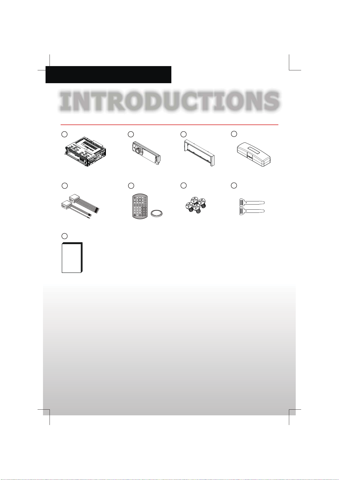
What’s in the box
1
5
9
Check and identify the contents of the package:
2
6
3
7
4
8
1 Main unit
2 Front panel
Trim plate
3
4 Carrying case for front panel
5 ISO male connector X 2
6 Romote control & battery
7 Screw X 4pcs (M5 x 8mm)
8 X 2 Disassembly tools pcs
9 User manual
2
INTRODUCTIONS
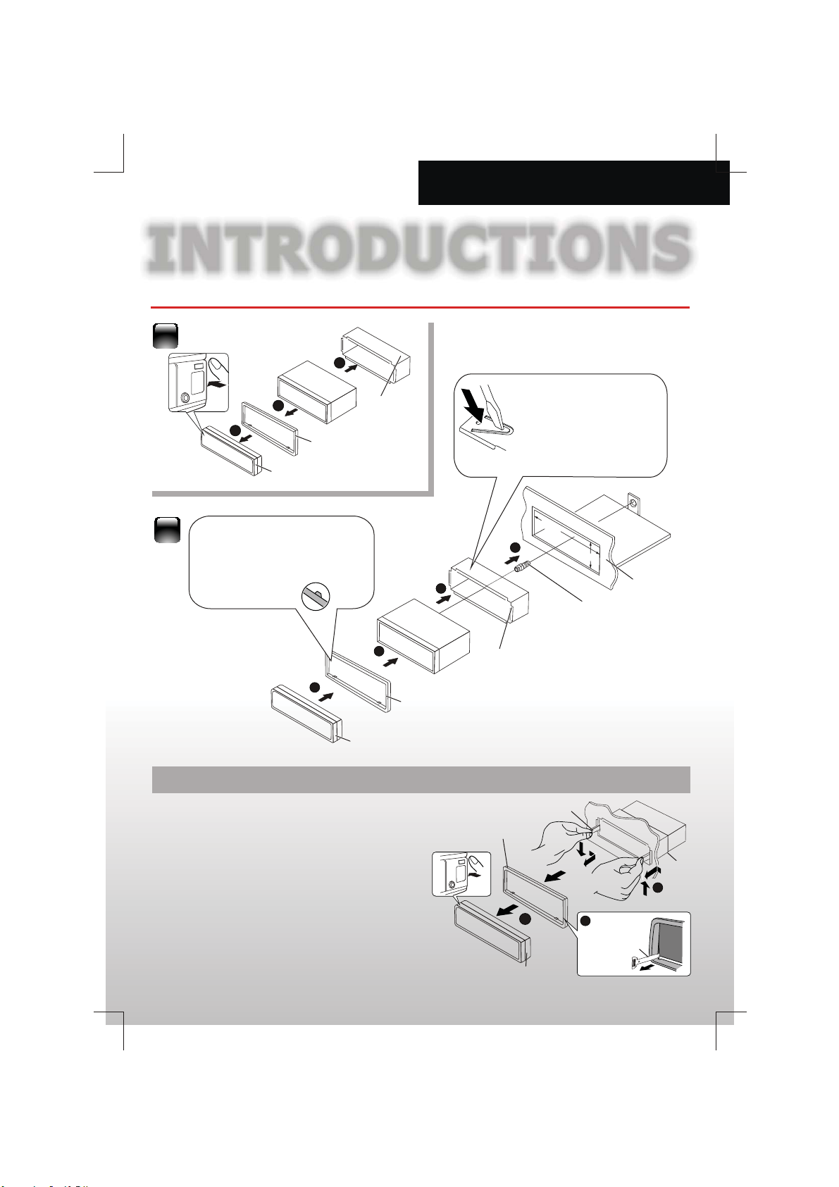
Installing the unit
1
3
Sleeve
2
2
1
Trim plate
Control panel
Before attaching, make
sure the direction of the
escutcheon is correct.
(Wider hook s on the
bottom side.)
3
4
Trim plate
Control panel
Removing the unit
1 Detach the control panel.
2 Engage the latch pin on the removal tools into the
holes on both sides of the escutcheon, then pull it
out.
3 Insert the disassembly tools deeply into the slots on
each side, then follow the arrows instructions as
shown on the right.
2
Sleeve
Trim plate
Bend the appropriate
tabs to hold the sleeve
firmly in place.
2
m
m81
1
Disassembly
1
35
mm
Screw
2
Dashboard
Sleeve
3
Disassembly
Control panel
3

INTRODUCTIONS
1
1
Wiring diagram
Optional
(Not included)
Subwoofer
REAR OUT LEFT
REAR OUT RIGHT
VIDEO OUT
Brake Switch
Ground
CAMERA INVIDEO OUT
REAR FRONT
Amplifier Amplifier
Parking Brake Wire (Pink)
Back Up Camera Wire (Orange)
CAMERA IN
FRONT OUT LEFT
FRONT OUT RIGHT
External Mic (Black)
Subwoofer (Blue)
3
45678
2
3
45678
2
PIN
WIRE COLOR
A1
NA
A2
NA
A3
NA
A4
YELLOW
A5
BLUE/WHITE
A6
NA
A7
RED
A8
BLACK
B1
VIOLET
B2
VIOLET/BLACK
B3
GREY
B4
GREY/BLACK
B5
WHITE
B6
WHITE/BLACK
B7
GREEN
B8
GREEN/BLACK
Video In (Yellow)
Audio In Right (Red)
Audio In Left (White)
OE IR Remote (Purple)
OE IR Remote Ground (Black)
Radio Antenna
FUSE
ISO Male
Connector
FUNCTION/LABEL
NA
NA
NA
BATTERY(+)
REMOTE
NA
IGNITION (ACC)
GROUND
RIGHT REAR SPEAKER (+)
RIGHT REAR SPEAKER (-)
RIGHT FRONT SPEAKER (+)
RIGHT FRONT SPEAKER (-)
LEFT FRONT SPEAKER (+)
LEFT FRONT SPEAKER (-)
LEFT REAR SPEAKER (+)
LEFT REAR SPEAKER (-)
4

INTRODUCTIONS
VOLUME
SUB
TITLE
DVD
AUDIO
DVD
MENU
TITLE
ANGLE
BAND
7
8
9
1
2
3
4
5
6
XBASS
EQ
DISP
0
MENU
LIST
GOTO
SETUP
Overview the unit
Press:
Auto seek / Track up/down
Hold:
Manual seek / fast forward & backward
Press:
Clock
nswer the call
A
Press:
transfer the call
Hold:
Press:
Adjust the function
Hold:
TFT dimmer
Rotate volume
& select items
HOME
Home
Press:
Hold:
Reject / End the call
Return/Exit
Menu List browser
Power
/ / / (Cursor)/OK buttons
Volume level
Tune for radio station
Skip/search for track
Fast backward/forward
EQ mode
XBass (booster function)
Number buttons
Setup menu
FUNC
LIST
EQ
Mute
Power
BAND
VOLUME
EQ
SETUP
Tuner band
Play/Pause
03:38
TUNER DISC USB SDHC
Front AUX
Press:
Hold:
MENU
XBASS
EQ
4
AV In
List browser
LIST
FUNC
DVD
AUDIO
SUB
TITLE
ZOOM
GOTO
BAND
DISP
DVD
MENU
TITLE
ANGLE
Open panel
OPEN
AUX
S
ettingBT Au d io
AUX socket
USB socket
Mute
Dimmer
Tuner band
Return/Exit
Play/Pause
Adjust the Function
Display video information
Clock
DVD playback control
5

INTRODUCTIONS
Select the playback source
Select Home
1.Access to Menu
HOME
03:38
TUNER DISC USB SDHC
Front AUX
AV In
S
ettingBT Audio
2. Select source
03:38
TUNER DISC USB SDHC
Front AUX
AV In
S
ettingBT Audio
Connect an external component
to the AUX input jack
You can connect an external component to the AUX
(auxiliary) input jack on the control panel.
03:38
FUNC
HOME
BAND
LIST
EQ
TUNER DIS C USB SDHC
Front AUX
AV In
OPEN
AUX
SettingBT Aud io
Play a USB device
03:38
FUNC
HOME
BAND
LIST
EQ
TUNER DISC USB SDHC
Front AUX
AV In
OPEN
AUX
S
ettingBT Aud io
USB input
terminal
03:38
TUNER DISC USB SDHC
Front AUX
AV In
Play a Micro SD device
03:38
TUNER DISC USB SDHC
S
ettingBT Audio
3.5 mm stereo mini plug
(not supplied)
Portable Audio
player,etc.
Right Track
Left Track
Ground
TUNER
DISC
USB
SDHC
Front AUX
BT Audio
AV In
SETTING
6
Front AUX
AV In
S
ettingBT Audio
Switch to the radio broadcast.
Play a disc.
Play files on a USB device.
Play files on a micro SD device.
Switch to an external component
connected to AUX input terminal
on the monitor panel.
Play files from your mobile phone
Switch the source to the audio and
video input that is transferred from
an external video player.
Adjust the Head unit settings

SUB
W
SUB
W
AUDIO ADJUSTMENT
General Setting/Equalizer
General Setting
Setting/Audio
HOME
Setting/ General
Beep
Time
Language
Dimmer
Auto Answer
BT
1a
1b
Confirm to select
Audio Settings
Bass
Middle
Treble
Fader
Balance
XBASS
Subwoofer
23
Setting/Audio
Bass
Setting/ General
Middle
Treble
Fader
Balance
Selectable setting
Adjust the bass range:-15 to +15
Adjust the middle range:-15 to +15
Adjust the treble range:-15 to +15
Adjust the front and rear speaker
out put balance:F01 to R12
Adjust the left and right speaker
out put balance: L01 to R12
Select the XBASS On or Off
Select the subwoofer On or Off
Bass
Middle
Treble
Fader
Balance
Beep
Time
Language
Dimmer
BT
Auto Answer
Gernal Settings
-2
Beep
Time
Selectable setting
Beep On / Off: Activates or
deactivates the keypress tone
12 Hour: Select 12 hour time format
24 Hour: Select 24 hour time format
Rock
ON
OFF
Language
Dimmer
BT Auto Answer
BT Info
Setting/ General
Beep
ON
Time
OFF
ON
OFF
Preset EQ
You can select a preset EQ from 8 music types.
When you select a preset EQ, the EQ icon will
light up.
03:38
SUB
00:03:10
-2
Language
Dimmer
ON
BT
Auto Answer
OFF
Setting/ General
Beep
Time
Language
Dimmer
BT
Auto Answer
Press to exit.
Adjust: Set time
Select the system language
Select dimmer high or low
Select the BT Auto answer On or Off
Check the bluetooth information
0168
0002
Rock
ALL
Rock
Everytime We To
Cascade
Ending Dreamgg
00:04:32
LIST
EQ
Hold press
SUB
03:38
00:03:10
Classic
Classic
Everytime We To
Cascade
CLASSIC
Ending Dreamgg
0002
0168
ALL
00:04:32
7

AV MEDIA
SUB
SUB
SUB
Listening to the radi o
Select BAND
BAND
03:38
SUB
FM1
87.5 108
Classic
P1
102.80
FM2
Select preset memory station
LIST
EQ
Tuner List
1
87.50
2
90.30
3
96.90
4
5
6
100.30
105.90
108.60
LOCAL
MHz
Radio function operation
Tuner Function
1
2
3
87.50
90.30
96.90
Manual Store
Auto Store
Local Seek
Radio Area
4
100.30
5
105.90
6
108.60
Classic
P1
87.50
FUNC
Manual Store FM 87.50
03:38
SUB
FM3
87.5 108
ON
USA
LOCAL
MHz
03:38
SUB
FM3
87.5 108
Classic
P1
87.50
LOCAL
MHz
TIPS
1. If no operation is done, for about 30
seconds, the operation will be
cancelled.
2. Press or to exit.
FUNC
8

AV MEDIA
SUB
W
SUB
W
Playing the music
Music browser
0168
03:38
SUB
00:03:10
Disc
Trac k 01
Trac k 02
Trac k 03
Trac k 04
Trac k 05
TIPS
1. Press to return to the previous
folder or exit.
2. Press to Quick return back now
playing mode.
When in browser, you can switch between
Music , photo and video select.
1
If no operation is done for about 30
seconds, the operation will be
cancelled.
LIST
2a 2b 2c
EQ
Track 01
Track 02
Track 03
Track 04
Track 05
Repeat step
3
*
Press
repeatedly
2 if necessary.
Press to exit.
1
if the device is not playing music, photo or
*
video file, it can not be selected .
0002
Classic
Everytime We To
Cascade
Ending Dreamgg
1
ALL
00:04:32
Folde r 01
Vide o 02
Vide o 52
Vide o 04
Vide o 05
LIST
EQ
Music function operation
0168
03:38
SUB
00:03:10
Media Function
Repeat
Random
1
FUNC
If no operation is done for
about 30 seconds, the
operation will be cancelled.
Function item Selectable setting
All
Repeat all song tracks or song files
Repeat
Random
One
Repeat all current track
Folder
Repeat all song files of the current folder
Off
Cancel random plays
ON
Randomly plays all disc or current folder
You cannot activate the repeat mode and the
random mode at the same time.
When in random off mode, you cannot activate
repeat off mode.
9
0002
ALL
ON
ALL
00:04:32
Repeat step 2 if
necessary.
Press or
to exit.
Classic
Everytime We To
Cascade
Ending Dreamgg
23
FUNC
FUNC

AV MEDIA
Viewing the photo
Basic operations
Photo is play as slide show automatically.
Start playback /pause the
slide show
Press to next & previous photo
Photo file list browser
LIST
Function operation
FUNC
Media Function
Slide Show
Brightness
Contrast
Color
Default
TIPS
EQ
1. If no operation is done, for about 30
seconds, the operation will be
cancelled.
ON
2
SDHC
Folder 01
Picture 02
Picture 52
Photo 04
Photo 05
To return to the previous folder or exit, press .
LIST
EQ
10
2. Press or to exit.
Function item
Slide Show
Brightness
Contrast
Color
Default
FUNC
Selectable setting
Turn the Slide Show On or Off
Adjust the brightness from 0 to 8
Adjust the Contrast from 0 to 8
Adjust the Color from 0 to 8
Reset to the factory settings

AV MEDIA
Playing Video
Basic operations
TT:11/22 CH:02/06 00:0021
PARKING is not enabled.
No video while driving.
No playback picture is shown when
the parking brake is not engaged.
Using the remote controller
Press will appear the video information, Press
again to disappear it.
Press and use the remote controller number
button, you can select your desired title, chapter,
time.
Ent er Ti tl e Numbe r :
/55 /01
Press to zoom in or zoom out the video.
Zoomx2,x3,x4, x1/2, x1/3,x1/4
Ente r Ch ap ter Numb er :
Title no./
Total title no.
Chapter no./
Total Chapter no.
Playback time
Enter Time:
/00:01:50: :
Video (AVI file) list browser
Video (VCD) browser
1. Song1
2. Song2
3. Song3
4. Song4
If play VCD2.0, press button, unit will
enter into VCD DISC MENU, then use the numeric
buttons on the remote to select songs or videos.
If play VCD1.0, press button, unit will
directly play the 1st song or
5. Song5
6. Song6
7. Song7
8. Song8
LIST
EQ
LIST
EQ
1st video.
Video (AV Receiver) browser
LIST
EQ
SDHC
Video 01
Video 02
Video 03
Video 04
Video 05
To return to the previous folder or exit, press.
LIST
LIST
EQ
MENU PLAY
Play all
Title play
AV Receiver setup
EQ
AV Receiver Browser is same as AV menu function.
AV menu is not same in different AV Receiver Disc.
11

AV MEDIA
Playing video
Function operation
FUNC
Media Function
Repeat
Subtitle
Brightness
Contrast
Color
VCD Function
Repeat
Channel
PBC
Brightness
Contrast
All
----
All
Stereo
Off
AV Audio
TIPS
1. If no operation is done, for about 30
seconds, the operation will be
cancelled.
2. Press or to exit.
Function item
Repeat
Channel
PBC
AV Audio
Subtitle
Angle
Aspect
Ratio
Brightness
Contrast
Color
Default
FUNC
Selectable setting
AVI: Repeat ALL/One/Folder
VCD: Repeat All/One/OFF
AV : Repeat OFF/Chapter/Title
For a VCD, to change the audio
channel.(Stereo/left/right)
For a VCD Disc, to select the PBC
(play back control) On or Off
For a AV receiver Disc, to change
the sound track language
For a AV receiver Disc, to change the
subtitle language recorded on the disc
For a AV receiver Disc, to change the
viewing angle
To select the monitor type to watch
a wide screen picture. (16:9, 4:3)
Adjust the brightness from 0 to 8
Adjust the Contrast from 0 to 8
Adjust the Color from 0 to 8
Reset to the factory settings
12

BLUETOOTH
SUB
Using bluetooth
You can make or receive phone calls with Bluetooth-enabled phones through
the unit. You can also listen to music from a Bluetooth-enabled device.
How to pair & connect device ?
NAKAMICHI
0000
Pairing code
“0000"
03:38
SUB
87.5 108
FM3
Classic
P1
BT Connect OK!
87.50
Connecting
Making a Call
You can dial number through the mobile phone.
Alan C han
Cal li ng.. .
0860 1018 7290 3
Receiving a Call
answer /accept the call
Alan Chan
Incom ing Call .. .
0860101872903
When conversation ends, press to terminate
the call.
Call Transfer
You can transfer voice from loudspeaker to mobile
phones during call.
MHz
Hold press
Bluetooth Audio Streaming A2DP
If the connected Bluetooth device supports Advanced
Audio Distribution Profile (A2DP), you can listen to the
music stored on the device through the unit. If the
device also supports Audio Video Remote Control
Profile (AVRCP) profile, you can use the control on the
unit or its remote control to play music
device.
03:38
HOME
TUNER DISC USB SDHC
Front AUX
AV In
TIPS
1. Press repeatedly to select [BT AUDIO].
HOME
2. Press to start play, press it again to pause.
3. To track up/down, press / .
SettingBT Audio
03:38
SUB
W
stored on the
0168
ALL
Classic
Everytime We To
Cascade
Ending Dreamgg
13

USB 1A CHARGING
USB Smart Phone 1A charging
This model supports USB 1A function, You can charge
charge your USB device, for example, smart phone,
with this product.
03:38
FUNC
HOME
TIPS
BAND
LIST
EQ
TUNER DISC USB SDH C
Front AUX
AV In
USB input
terminal
1. Slide the USB socket to left.
2. Insert the iPhone or Smart Phone device into the
USB socket.
3. Once the iPhone or Smart Phone is connected and
recognized, the iPhone/Smart Phone begins to
charge.
OPEN
AUX
SettingBT Audi o
14

REFERENCE
Specifications
TFT Monitor section
Screen Size
Display Resolution :320x240 dots
Aspect Rat io
:3.0 inches
:16:9(wide)
Disc player section
Disc Diameter:
Frequency Re spo ns e
Signal/Noise Rati o
Dynamic Range :90dB
Video Signal Forma t
12cm
:
:
17Hz - 20kHz
:8
5 dB
:NTSC
USB interface section
USB Standard :USB 1.1 Full Speed
File Syste m :FAT 32/16/12
Maximum Current
Compatible Device
:DC 5V 1A
:Mass storage class
Memory Card section
Memory Cards
Maximum Capacity
:Micro SD
:32G
Radio section
Frequency FM range
Frequency AM(MW) range
Usable sensitivity : 9dB(2.8uV (FM))
: 87.5 - 1 0 7.9 MHz
: 520-1710 KHz
: 20 uV/55dB (AM)Sensitivity / Selectivity
Video section
Color Sys tem of
External Video Input
(RCA)
: NTSC/PAL
: 1 Vp-p /75Ω
Audio section
Maximum Powe r
Continuous Power Output
(RMS)
Preout Level (V)
Preout Impedance
Speaker Impedance
: 50Wx4
: 24 Wx4
: 4 V
: 10kΩ
: 4-8 Ω
General
Operating Vo lt age : 14.4V(11-16 V)
Dimension(WxHxD)
Operational Temperature
Range
Storage Te m p eratu r e
Range
: 178x48x172mm
: 0°C-+40°C
: -10°C-+60°C
Bluetooth
Output power: Class 2
Frequency band: 2.4000GHz-2.4835GHz ISM Band
Range: 3 meters (free space)
Standard: Bluetooth 3.0 specification
USB Smart Phone 1A charging
Output Voltage : 5 V DC
Output Current : 1000 mA (1A)
15

C
Design and specifications are subject to change
without notice
2014 Nakamichi
www.nakamichicaraudio.com
 Loading...