

Page 1
SM-CCR3701M
Мультимедийный ресивер 2 DIN с 7” сенсорным TFT-дисплеем, ТВ-тюнером и
Bluetooth Руководство по эксплуатации
2 DIN Multimedia receiver with 7” TFT touch screen display, TV tuner and
Bluetooth Instruction manual
Page 2

2
Dear customer!
Thank you for purchasing our product. For safety, it is strongly recommended to read this manual carefully
before connecting, operating and/or adjusting the product and keep the manual for reference in the future.
Table of contents
Safety Precautions...................................................................................................... 2-3
Installation.................................................................................................. 4-5
Wiring Connections...................................................................................................... 6-7
Basic Operation............................................................................................................... 8
Radio Operation............................................................................................................ 9
TV Operation................................................................................................................. 10
Bluetooth Operation................................................................................................. 11
USB/SD Operation.................................................................................................... 12
Steering Wheel Control................................................................................................ 13
Smartphone Mirroring by HDMI................................................................................ 14
Other Operations........................................................................................................... 15
Maintenance...................................................................................................... 16
Infra Red Remote Control........................................................................................... 17
Simple Troubleshooting Guide...................................................................................... 18
Specifications...................................................................................... 19
Page 3

3
Important safeguards
• Read carefully through the manual to familiarize yourself with this unit.
• Keep this manual handy as a reference for operating procedures and precautions. Do not allow persons who have not
read through this manual to use this unit.
• Do not allow this unit to come into contact with liquids. Electrical shock could result. Also, damage to this unit, smoke,
and overheating could result from contact with liquids or dust. Protect this unit from moisture.
• Make sure that foreign objects do not get inside the unit; they may cause malfunctions, or create safety hazards such
as electrical shock or laser beam exposure.
• The beginning of operation is the moment of the unit installation. Before use the device in winter it is recommended to
heat up the passenger compartment during 20 seconds or to the operation temperature.
• Using the unit with the temperature that goes beyond the operation temperature greatly decreases the operation
resource of the screen and other components of the unit and can result in an outage.
• Disconnect the vehicle’s negative battery terminal while mounting and connecting the unit.
• The unit is designed for negative terminal of the battery, which is connected to the vehicle metal. Please ensure it
before installation.
• When replacing the fuse, be sure to use one with an identical amperage rating. Using a fuse with a higher amperage
rating may cause serious damage to the unit.
• Do not allow the speaker wires to be shorted together when the unit is switched on. Otherwise it may overload or
burn out the power amplifier.
• Make sure you disconnect the power supply and aerial if you will not be using the system for a long period or during a
thunderstorm.
• Make sure you disconnect the power supply if the system appears to be working incorrectly, is making an unusual
sound, has a strange smell, has smoke emitting from it or liquids have got inside it. Let a qualified technician check the
system.
• Always keep the volume low enough so that you can hear sounds from outside the vehicle.
• Should this product fail to operate properly, contact your dealer or nearest service center.
Page 4

4
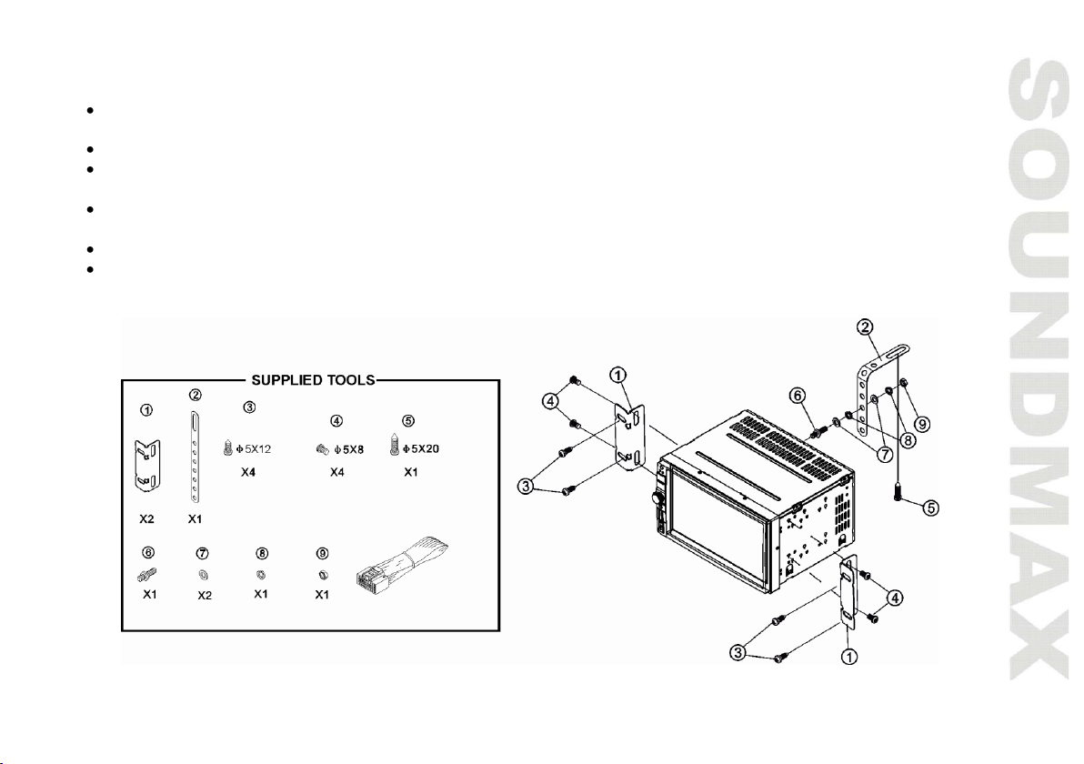
Accessories
1. Media player 1 pc
2. Remote controller 1 pc
3. ISO connector 1 pc
4. Mounting parts:
Mounting bracket 2 pcs
Steel bar 1 pc
Screw B 5x20 1 pc
Nut M5 1 pc
Flat washer 2 pcs
Spring washer 2 pcs
Bolt M5 1 pc
Screw B 5x12 4 pcs
Screw B 5x6 4 pcs
5. Consumer information 1 pc
6. Warranty card 1 pc
7. Instruction manual 1 pc
Page 5
5
Installation/Connections
Choose the mounting location where the unit will not interfere with the normal driving function of the
driver.
Before finally installing the unit, connect the wiring and make sure that the unit works properly.
Consult with your nearest dealer if installation requires the drilling of holes or other modifications of the
vehicle.
Install the unit where it does not get in the driver's way and cannot injure the passenger if there is a
sudden stop, like an emergency stop.
If installation angle exceeds 30° from horizontal, the unit may not perform properly.
Avoid installing the unit where it would be subject to high temperature, such as from direct sunlight, or
from hot air, from the heater, or where it would be subject to dust, dirt or excessive vibration.
Page 6

6
Mounting
• Connect the cable set and the antenna to the vehicle’s electronics corresponding to the connection table
(see farther).
• Attach the mounting racks to the sides and to the back of the unit, and fix them with the screws.
• Insert the unit into the slot until the stop. The unit then audibly snaps.
• Fasten the screws to fix the unit.
• The device is distinguished by a high degree of output. During operation, this results in a strong heat
generation. Therefore no cables or other parts may adjoin the device. If their insulation melts, there is the
risk of a short circuit or fire.
• Removing: Turn off the device. Clamp off the negative pole of the vehicle battery for the duration of the
disassembly. Unscrew the four screws. Remove carefully the unit from the slot and disconnect all wires. Make
sure that no vehicle cable can cause a short circuit after the device has been unplugged.
Page 7
7
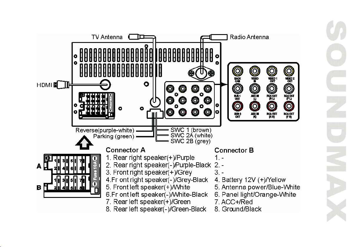
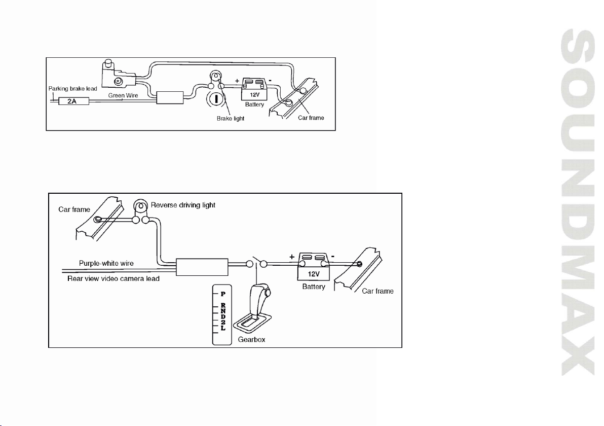
Connection diagram
Page 8
8
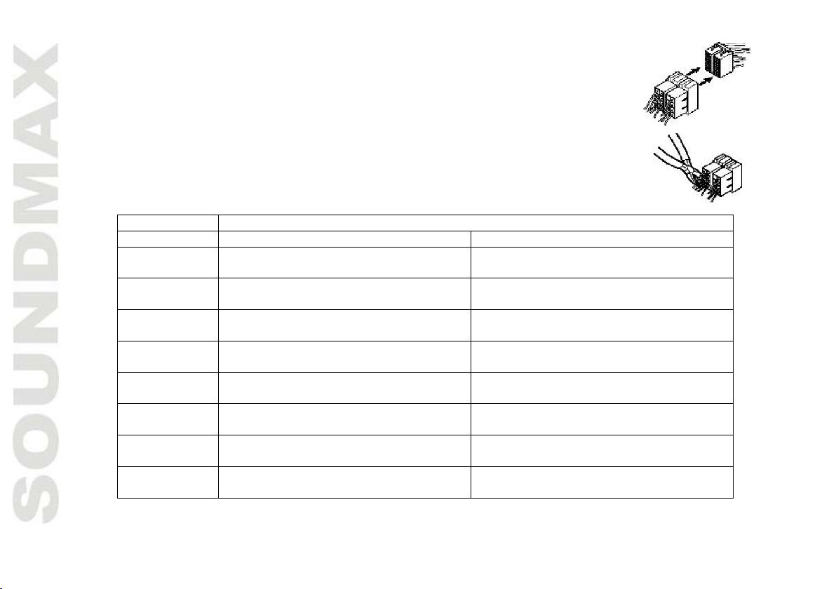
Using the ISO Connector
Location
FUNCTION
Connector A
Connector B
1
Rear right speaker (+)/Purple
-
2
Rear right speaker (-)/Purple-Black
-
3
Front right speaker (+)/Grey
-
4
Front right speaker (-)/Grey-Black
Battery 12V (+)/Yellow
5
Front left speaker (+)/White
Antenna power/Blue-White
6
Front left speaker (-)/White-Black
Panel light/Orange-White
7
Rear left speaker (+)/Green
ACC+/Red
8
Rear left speaker (-)/Green-Black
Ground/Black
1. If your car is equipped with the ISO connector, then connect the ISO connectors
as illustrated.
2. For connections without the ISO connectors, check the wiring in the vehicle
carefully before connecting, incorrect connection may cause serious damage to
this unit.
Cut the connector, connect the colored leads of the power cord to the car battery as
shown in the colour code table below for speaker and power cable connections.
Power antenna wire is intended for power supply of the antenna and for remote control of an additional
amplifier.
Page 9
9
Parking wire connection
If Parking cable is connected to hand brake switch, the video display of the TFT monitor will be controlled by driving status,
system setup and input video sources. When the car is moving ahead, if the video disc is played, the screen shows a
warning message. The warning screen will prevent the driver from watching images.
Reverse driving cable connection
If the rear view video camera is connected, the unit automatically switches to camera picture during reverse driving. The
unit returns to the original work mode after the reverse driving is done.
Page 10
10
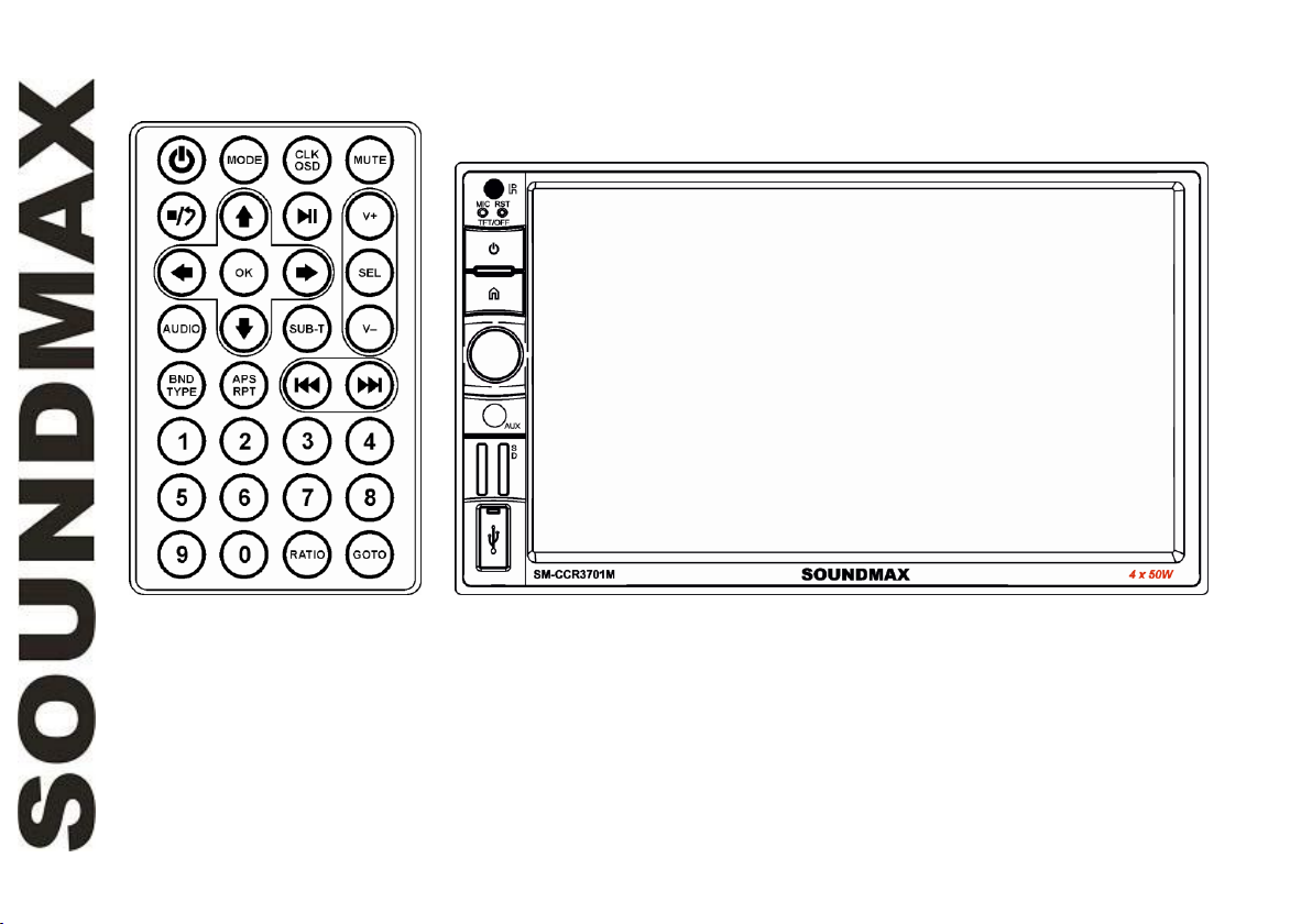
Panel controls
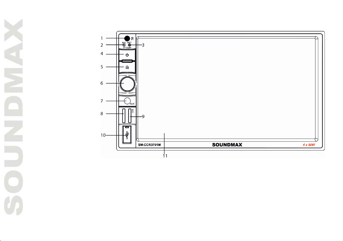
Front panel
1. IR sensor
2. Microphone
3. Reset button (hole)
4. POWER button
5. HOME button
6. VOLUME knob/
Select button
7. AUX input
8. Unavailable
9. SD card slot
10. USB slot
11. Display
Page 11
11
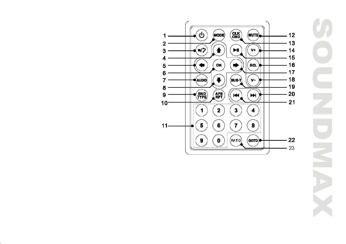
Remote controller
1. Power On/off
2. Mode Switch Button
3. Stop Playback
4. Navigation Up
5. Navigation Left
6. Enter Button
7. Change The Audio Output Method
8. Navigation Down
9. Band/Select Type
10. Auto Preset Scan/Repeat Play
11. Tuning/Music Selection (numeric key)
12. Mute Sound Button
13. Time Clock Display/Statistical Disc
Information Display Button
14. VOL +
15. Play/Pause Function
16. Sound Select Button
17. Navigation Right
18. VOL -
19. Subtitle Language Switching Key
20. Next Track/Next Radio Station
21. Previous Track/Previous Radio Station
22. GO TO Button (track selection)
23. Aspect Ratio Button
Page 12
12
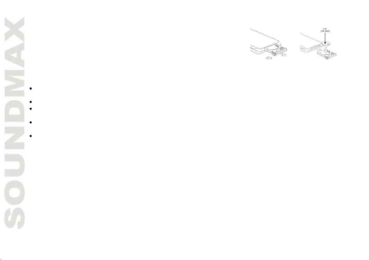
Changing the battery
Pic. 1
Pic. 2
1. Press the catch and at the same time pull out the battery tray (pic. 1).
2. Insert the 1 lithium battery, type CR2025 (3V) battery with the stamped
(+) mark facing upward. Insert the battery tray into the remote controller
(pic.2).
Warning:
Store the battery where children cannot reach. If a child accidentally swallows the battery, consult a
doctor immediately.
Do not recharge, short, disassemble or heat the battery or dispose it in a fire.
Do not expose or bring into contact the battery with other metallic materials. Doing this may cause the
battery to give off heat, crack or start a fire.
When throwing away or saving the battery, wrap it in tape and insulate; otherwise, the battery may give
off heat, crack or start a fire.
Please direct the Remote controller to the IR sensor of the front panel.
Page 13

13
General operations
Touch screen
Due to the touch screen, you can fulfill most functions not only by pressing buttons but also by touching the
options you need.
Turning the unit on/off
Press the POWER Button to turn the unit on. When the unit is on, press the POWER Button once to turn the
TFT off. During TFT off, the video out signal will be available so that the connected monitor will show the
screen of the unit. Press the POWER Button again to turn the TFT back on. Press and hold the POWER button
again to turn the unit off..
Reset the unit
Operating the unit for the first time or after replacing the car battery, you must reset the unit. Press reset
button on the unit with a pointed object (such as a ballpoint pen) to set the unit to initial state.
When some errors occur on the display, you can also press reset button to resume to normal, and it will
erase the clock setting and some memorized functions.
Setting the sound characteristics
• Volume: Use the VOL +/- Button to adjust the volume level. Turn the button clockwise to increase the
volume, and vice versa. The larger the number of volume, the higher the volume level. You can also adjust the
volume by sliding the volume icon on top of the screen.
• Bass: Press the SEL Button on the RC until the display shows “BAS”. Use the VOL +/- Button to adjust.
When EQ is ON, bass control is not available.
• Treble: Press SEL Button on the RC until the display shows “TRE”. Use the VOL +/- Button to adjust. When
EQ is ON, treble control is not available.
Page 14

14
• Balance: Press SEL Button on the RC until the display shows “BAL”, then use the VOL +/- Button to adjust
the balance between the left & right speakers.
• Fader: Press SEL Button on the RC until the display shows “FAD”, then use the VOL +/- Button to adjust the
balance between the front & rear speakers.
• Other Audio Settings: You can adjust other audio settings like preset equalizer, loudness or subwoofer
ON/OFF by tapping the “EQ” icon on the main menu, or on the control menu of other audio/video play modes.
Mute function
Press MUTE button on the RC to turn off the sound. Press the button again or adjust volume to resume the
sound output.
Mode selection
Press the MODE Button to cycle the Play Modes between RADIO, BT (Bluetooth), USB, SD and AUX in.
RCA output
The RCA Output is on the back of the unit. (Refer to Wiring Diagram) This output is for connecting amplifier,
equalizer, or other audio component that requires a pre-amp out connection. (Red=Right, White=Left) Follow
the manufactures instructions for the audio component that you are connecting.
AV in jack
The Video Output Jack is on the back of the unit. (Refer to Wiring Diagram) This output (in yellow) is for
connecting monitor(s). You must connect a monitor for car in order to play this unit in another monitor. Consult
your dealer for any kinds of monitors that are suitable to use in car.
Page 15

15
Subwoofer
The Subwoofer Output is on the wire harness. (Refer to Wiring Diagram) This output is designet for
connecting up to 2 subwoofers to the unit. Follow the amplifier’s installation instructions. You can turn the
subwoofer on/off by pressing the icon in the main menu.
Rear view camera function
The rear view camera input is on the back of the unit. (refer to wiring diagram). This input (in yellow) is for
connecting backup camera for parking. You must connect the VCC wire (in pink color) to the reverse gear
switch in order to activate this video input mode when you switch the reverse gear of your car. Please refer
to the wiring diagram for more details.
Page 16

16
Bluetooth
PAIRING
At BT mode, search bluetooth device by the phone and “BT CAR STEREO” will appear in your phone. Input
“0000” as password to establish connection.
DIAL PAD
Touch the dial pad to dial the number you would like to call. Touch the CALL (green) button to send the
number.
CALL RECORD
Press the HISTORY button to enter the phone book page to view received, missed and dialed calls. More
details in the next page.
A2DP
Press the MUSIC button to enter the A2DP page to control playing music of your cellphone. More details in
the next page.
REJECT CALL
Press the REJECT (red) button to end the call or to reject an incoming call.
RETURN TO USER INTERFACE
Touch the arrow key on the top right corner to return to the main user interface.
VIEW RECEIVED CALLS
Page 17

17
Touch the RECEIVED CALLS button, the received calls will be displayed. There will be up/down arrows
displayed for you to view them one by one.
VIEW MISSED CALLS
Touch the MISSED CALLS button, the missed calls will be displayed. There will be up/down arrows displayed
for you to view them one by one.
VIEW DIALED CALLS
Touch the DIALED CALLS button, the dialed calls will be displayed. There will be up/down arrows displayed
for you to view them one by one.
PLAYING MUSIC ON YOUR CELLPHONE
After activating music player in the cellphone and selecting “Play via bluetooth”, touch PLAY/PAUSE to play or
pause the music. Touch PREVIOUS or NEXT to select down or up one song in your song list.
Page 18

18
Radio operations
Band select
In Radio mode press the BAND button onscreen to choose among the five radio bands - three FM Bands
(FM1, FM2, and FM3) and two AM Bands (AM1, and AM2). Each of the five bands can store up to six preset
stations, for a total of 30 preset memory stations.
Auto/Manual tuning
• Automatic tuning: In Radio mode, touch and hold PREVIOUS or NEXT button to adjust the radio
frequency automatically. The radio will seek to the next or previous strong and clear frequency station
automatically. Repeat this action to seek for other desired stations. To stop automatic search, press one of
these buttons. Or press repeatedly shortly or button on the RC to manually adjust the radio frequency.
• Manual tuning: Press repeatedly shortly or button on the RC to manually adjust the radio frequency.
Automatic store/preset scan
There are six numbered preset buttons on the the screen (P1-P6) which can store and recall stations for
each band. While listening to a radio station you would like to save as a preset, touch and hold any key from
P1-P6 until you hear a beep. The station will be saved in the designated number.
Mono/Stereo control (in FM radio mode)
In FM radio mode, touch the ST button to select stereo or mono reception. ST ON means stereo reception of
the signal; ST OFF means mono reception mode. Improvement of reception of distant stations can be done by
selecting mono mode, which may cut down some reception noise.
Page 19

19
Local radio station search
In radio mode, touch the LIST button and then the LOC button to select local or distance reception. LOC ON
means that only local stations are received; LOC OFF means that both local and distant stations with weak
and strong signal are received.
RDS function
RDS (Radio Data System) service availability varies with areas. Please understand if RDS service is not
available in you area, the following service is not available, either.
AF (Alternative Frequencies) function
Press LIST button to show the function list; tap AF to select AF ON or AF OFF.
When the function is on, AF symbol will light up on the display.
When the radio signal strength is poor, enabling the AF function will allow the unit to automatically search
another station with the same PI (Program Identification) as the current station but with a stronger signal, so
that you do not have to retune the stations when driving between different transmitter coverage areas.
PS (Program Service name): the name of station will be display instead of frequency.
If RDS service is not available in your area, turn off the AF mode.
TA (Traffic Alarm) function
Press LIST button to show the function list; tap TA to select TA ON or TA OFF.
When TA is on, the TA symbol will show on the display.
In TA mode traffic program will be automatically searched, until the program is received. When traffic
announcement is received the unit will temporarily switch to the tuner mode (regardless of the current mode)
and begin broadcasting the announcement. After the traffic announcement is over, it will return to the
previous mode and volume level.
Page 20

20
PTY (Program Type)
Press LIST button to show the function list; tap PTY to select PTY ON or PTY OFF. When PTY is selected, the
radio starts to search corresponding PTY information, and stops if the corresponding PTY information is
detected. If no buttons are pressed within several seconds, previously selected PTY is searched. During 1
loop, if desired PTY is not found, the unit will return to previous mode.
TV tuner operations
SCAN
Press SCAN to seek all strong and clear frequency stations available and store them.
Press PREVIOUS/NEXT buttons to seek another station.
Saved channels
When you reach the desired TV channels, they will be automatically saved for you to recall later.
Selecting saved channels
Press cursor Buttons to select the saved stations up or down.
GOTO
Tap the GOTO button on the bottom menu, then you will enter a screen for you to input the exact frequency
of TV station. After putting the information, tap the OK button and the unit will go to the desired radio
frequency.
SYSTEM
To switch your television system, tap the SYSTEM button on the right of the screen. The sequence will be
shown as follows: PAL M => PAL N => NTSC MN => PAL I =>SECAM DK.
Page 21

21
AUDIO
To switch the audio system, tap the AUDIO button on the right of the screen. The sequence will be shown
as follows:
SECAM BG => SECAM DK
ENTER
When TV is playing, tap the screen anytime to come back to the TV menu. Press ENTER to resume playing.
USB/SD operations
USB/SD/MMC notes
USB format supports 1.1. Capacity: up to 1 TB.
For correct and satisfactory operation, licensed micro SD memory cards of famous brands should be used
with this unit. Avoid using memory cards of unknown brands. Capacity: up to 32 GB.
According to the USB 1.1/2.0 Standard, usage of a USB device with power current consumption exceeding
500 mA is not recommended without supplementary power supply. Failure to use supplementary power for
connected USB drives with power consumption exceeding this value as well as defective USB drives may
cause mechanical or thermal changes of elements of this unit as well as failure of internal elements of the
USB port. Such damages are not warrantee cases.
Warning: usage of external USB drives containing BIN files in the root directory may cause malfunction of
the unit or damage to the software.
Inserting an SD card/USB device
Insert an SD memory card into the card slot. Open the USB slot cover on the front panel and insert a USB
into the USB slot.
Page 22

22
HOME button
Press the HOME button during playback in order to see the full list of files along with file types. All the file
names are displayed for your easy reference. Select the desired file types and file names by tapping on the
screen.
Aspect ratio
During video playback, tap the screen or press the RATIO button to switch the aspect ratio of the video. On
the menu you can select full screen, 16:9, and 4:3 accordingly. The viewing effect will depend on the video
file so it may vary.
Play/pause
Press PLAY/PAUSE button on the RC to pause playback, press it again to resume playback.
Selecting tracks
During playback press PREV. button on the RC or on the screen to play the previous track. Press NEXT
button on the RC or on the screen to play the next track. Press number buttons (0-9) on the RC to select
the desired track/chapter.
Fast forward/rewind
Press and hold the forward or rewind icons on the touch screen during audio playback. The unit will fast
forward/rewind the song/video until you release.
When fast backward/forward playback reaches the previous or next track, the unit will resume normal
playback.
Other settings
Page 23

23
During playback, you can adjust other settings including random/repeat play, and sub-title/audio channel,
etc, by tapping on the menu list on the button of the screen. During video playback, tap the screen once
and the menu list will show up.
Steering wheel control (SWC)
Refer to the wiring diagram for connection. The brown wire (SWC 1) must be connected, then the
white or grey (SWC 2A and 2B) will be connected depending on the total number of the wire from the
steering wheel remote control of your vehicle.
Tap steering wheel logo in the OSD. Press RESET before the set up. Select from the 10 functions
according to the number of available keys on the steering wheel of your vehicle. Press any key on your
steering wheel, then tab the function key you would like to assign. The frequency of the function will be
shown on the display. Repeat the step for other keys on the steering wheel. Tap ENTER after your set up is
complete and then you can operate the unit by your steering wheel.
Page 24

24
Smartphone mirroring by HDMI
This unit is equipped with an HDMI input for connection with smartphones, DVBT-2 receivers, media players
and any devices with HDMI output.
CONNECTION WITH ANDROID PHONE (MHL)
Connect any Android phone with MHL (Mobile High Definition Link) support. You need to have an MHL
adaptor (not included). After connection, the sound and image of the phone will be mirrored on the screen of
the unit, so that you can display the cellphone and make use of its resources such as navigation, photo/video
sharing and presentation.
CONNECTION WITH IPHONE (4S OR LATER)
Connect your iPhone with HDMI output capability. You need to have an HDMI adaptor (not included). After
connection, the sound and image of the iPhone will be mirrored on the screen of the unit, so that you can
display the iPhone and make use of its resources such as navigation, photo/video sharing and presentation.
To determine if your smartphone supports MHL, please check your phone’s specifications for MHL
connectivity. See the list of supported smartphones below.
The unit only works with original iPod 30 pin to HDMI (for iPhone 4S), or Lightning to HDMI adaptor (for
iPhone 5 and later). Using generic adaptors may not be compatible with our product and may produce no
image and sound.
List of Android Smartphone’s with MHL support
At the time of unit manufacture the following smartphones of major brands support the MHL function
(please check your phone specifications if you cannot find it in the list):
SAMSUNG
Galaxy Note 3, Galaxy Tab 3 8”, 10.1”, Galaxy S4, S4 Active, S4 Zoom, Galaxy Mega 6.3/5.8
Galaxy Note 8, Galaxy Express, Galaxy Note II, Galaxy S III, Galaxy Nexus 2, Galaxy Note 5.3”, Captivate
Glide, Epic 4G Touch, Galaxy S II
Page 25

25
HTC
Butterfly, Butterfly S, Droid DNA, One, One XL,
One X+, One X, One S, EVO, Raider, Velocity, Vivid, Rezound, Amaze, Sensation XE, JetStream, Sensation
4G, EVO View 4G, EVO 3D, Sensation, Flyer.
LG
Optimus GJ, Optimus G, Optimus 4X HD, Optimus LTE II, Optimus LTE Tag,
Optimus 3D Max, Optimus Vu, Spectrum, Prada, Nitro HD.
SONY
Xperia Z1, Xperia Z Ultra, Xperia UL, Xperia ZR, Xperia AC, Xperia Tablet Z, Xperia SP, Xperia Z, Xperia ZL,
Xperia TL, Xperia TX, Xperia T, Xperia V, Xperia GX, Xperia SX.
Cleaning
Cleaning the cabinet
Wipe with a soft cloth. If the cabinet is very dampen (not dropping wet) the cloth with a
weak solution of soapy water, and then wipe clean.
Page 26

26
Troubleshooting guide
Symptom
Cause/Solution
No Power
Check whether the fuse is blown, replace with fuse of proper value if necessary
Unit stops
responding or
shows error.
Press the RESET button.
Unable to
receive radio
stations.
Check whether the antenna is inserted or the antenna is properly connected.
Poor effect on
receiving a
station.
-Antenna may not be of the proper length. Make sure the antenna is fully extended. If broken,
replace the antenna with a new one.
-The broadcasting signal is weak.
-The antenna is poorly grounded; check and make sure the antenna is properly grounded at its
mounting location.
No pictures
-The video line from main unit to monitor is not connected properly (for external monitor)
-The purple brake wire is not grounded or connected to brake properly.
The picture
appears grainy
-Check the color system. (PAL or NTSC)
Below is a table describing simple measures that can help you eliminate most problems likely to emerge
when this unit is in use. If below measures do not help, turn to a service center or to the nearest dealer.
Page 27

27
Specifications
General
Power supply: 12 V DC
Maximum power output: 4 x 50 W
Dimensions/Net weight 178 x 138 x 100 mm/1.7 kg
Mounting angle 0 to +/-300
Working temperature range -200С - +600С
Display
Display 7” TFT
Resolution: 800 (RGB) x 480
Aspect ratio: 16:9
Contrast ratio: 500:1
Brightness: 400 cd/m2
View angle: 1200
FM Stereo Radio
Frequency range: 65.0 – 74.0/87.5 – 108.0 MHz
Preset memory stations: 18
AM Radio
Frequency range: 522 kHz - 1620 kHz
Preset memory stations: 12
TV Tuner
Color System: PAL/SECAM
Tuning Range: 48.25 – 863.25 MHz
Player
Supported storage USB/micro SD
Supported formats MP3/WMA/OGG/AAC/RMVB/FLV/TS/TP/M2TS/AVI/
MPEG4/MOV/MKV/MPG/VOB/PMP/RM(DivX/XviD)
Specifications are subject to change without notice. Dimensions are approximate.
Page 28

28
Уважаемый покупатель!
Благодарим Вас за покупку нашего изделия. Для обеспечения безопасности рекомендуется тщательно
изучить настоящее руководство перед подключением, эксплуатацией и/или регулировкой изделия, и
сохраняйте руководство для использования в будущем.
Содержание
СОДЕРЖАНИЕ .................................................................................................................................................................... 28
МЕРЫ ПРЕДОСТОРОЖНОСТИ ...................................................................................................................................... 29
КОМПЛЕКТ ПОСТАВКИ .................................................................................................................................................. 31
УСТАНОВКА/ПОДКЛЮЧЕНИЕ ...................................................................................................................................... 32
ЭЛЕМЕНТЫ УПРАВЛЕНИЯ ............................................................................................................................................. 37
ОБЩИЕ ОПЕРАЦИИ ......................................................................................................................................................... 40
НАСТРОЙКА СИСТЕМЫ .................................................................................................................................................. 42
ОПЕРАЦИИ С РАДИО ...................................................................................................................................................... 48
ЧИСТКА И УХОД ............................................................................................................................................................... 49
РУКОВОДСТВО ПО УСТРАНЕНИЮ НЕИСПРАВНОСТЕЙ ..................................................................................... 50
ТЕХНИЧЕСКИЕ ХАРАКТЕРИСТИКИ ............................................................................................................................ 51
Page 29

29
Меры предосторожности
• Внимательно изучите данное руководство, чтобы ознакомиться с устройством.
• Держите данное руководство под рукой в качестве справочника по правилам эксплуатации и мерам
предосторожности. Не допускайте к использованию устройства посторонних лиц, не ознакомившихся и
не усвоивших данные инструкции по эксплуатации.
• Не допускайте попадания жидкости на устройство. Это может повлечь поражение электрическим
током. Кроме того, попадание жидкости или пыли в устройство может стать причиной его выхода из
строя, перегрева и появления дыма. Оберегайте устройство от воздействия влаги.
• Убедитесь, что внутрь устройства не попали посторонние предметы. Они могут вызвать сбои в работе
или стать причиной возгорания или поражения лазерным лучом.
• Началом эксплуатации устройства считается момент его установки в автомобиль. Перед началом
использования устройства в зимний период рекомендуется прогреть салон автомобиля в течение 20
минут или до достижения эксплуатационного диапазона температуры устройства.
• Использование устройства при температуре, выходящей за рамки эксплуатационного диапазона
температур, значительно снижает ресурс работы экрана и других компонентов устройства и может
привести к выходу устройства из строя.
• При установке и подключении устройства отключите отрицательную клемму аккумулятора
автомобиля.
• Устройство разработано таким образом, чтобы отрицательный вывод аккумулятора был подключен
к корпусу транспортного средства. Пожалуйста, убедитесь в этом перед установкой.
• При замене предохранителя, убедитесь, что вы устанавливаете предохранитель с тем же
номиналом. Используя предохранитель с повышенным значением тока, можно причинить значительные
повреждения устройству.
• Не позволяйте проводам динамиков соприкасаться друг с другом или с корпусом автомобиля после
включения устройства. В противном случае усилитель может быть перегружен или выйти из строя.
Page 30

30
• Убедитесь, что источник питания и антенна отключены, если Вы не будете пользоваться
устройством в течение длительного времени или во время грозы.
• Убедитесь, что источник питания отключен, если обнаружена неправильная работа устройства,
устройство издает нехарактерные звуки, запах, выделяет дым или внутрь его попала жидкость. В этих
случаях необходим квалифицированный технический осмотр устройства.
• Не устанавливайте уровень громкости, заглушающий внешние звуки дорожной обстановки и
сигналы специального автотранспорта.
• При неполадках в работе устройства свяжитесь с торговым представителем или с ближайшим
сервисным пунктом.
Page 31

31
Комплект поставки
1. Ресивер 1 шт
2. Пульт дистанционного управления 1 шт
3. ISO-коннектор 1 шт
4. Детали для установки:
Монтажная скоба 2 шт
Металлическая пластина 1 шт
Винт M5х20 1 шт
Гайка M5 1 шт
Плоская шайба 2 шт
Пружинная шайба 2 шт
Крепежный болт М5 1 шт
Шуруп М 5х12 4 шт
Шуруп М 5х6 4 шт
5. Информация для потребителя 1 шт
6. Гарантийный талон 1 шт
7. Руководство по эксплуатации 1 шт
Page 32

32
Установка/Подключение
Перед окончательной установкой устройства временно подключите все провода и убедитесь, что все
соединения выполнены верно, а устройство и система работают правильно.
Для обеспечения правильной установки устройства используйте только те детали, которые входят в
комплект. Использование других приспособлений может привести к появлению сбоев в его работе.
Если для установки устройства необходимо сверлить отверстия в кузове автомобиля или вносить
какие-либо другие изменения в его конструкцию, проконсультируйтесь с продавцом.
Устанавливайте устройство там, где оно не будет закрывать водителю обзор и отвлекать от
дорожной обстановки и не сможет нанести травм пассажирам в случае внезапной остановки
автомобиля, например, при экстренном торможении.
Если при установке устройства угол относительно горизонтальной плоскости превышает 30°,
рабочие характеристики проигрывателя могут быть не оптимальны.
Никогда не устанавливайте устройство в таких местах, где оно будет подвергаться воздействию
высокой температуры, например, в местах попадания прямых солнечных лучей, в местах выхода
горячего воздуха от отопителя автомобиля, в местах, где очень грязно или пыльно, или там, где
устройство будет подвергаться сильной вибрации.
Page 33

33
Установка устройства в приборную панель
• Подсоедините аудио-видеоконнектор к соответствующему разъему на задней панели устройства в
соответствии со схемой электрических подключений (см. далее).
• Прикрепите крепежные скобы к боковым панелям и задней панели устройства с помощью винтов .
• Вставьте устройство в слот до упора.
• С помощью 4 винтов прикрепите устройство спереди.
• При работе устройство может сильно нагреваться, поэтому кабели не должны касаться корпуса
устройства. При плавлении оплетки кабелей возможно короткое замыкание.
• Извлечение устройства из приборной панели: Отключите питание устройства. Отключите клемму с
отрицательного полюса аккумулятора автомобиля. Выверните четыре фронтальных винта. Извлеките
устройство из слота и отсоедините все кабели.
Page 34

34
Схема подключения
Page 35

35
Использование разъема ISO
Номер
Функция
Разъем A
Разъем B
1
Тыл. прав. динамик(+)/Фиолетовый
-
2
Тыл. прав. динамик(-)/Фиолетовыйчерный
3 Фронт. прав. динамик(+)/Серый
-
4
Фронт. прав. динамик(-)/Серыйчерный
Питание 12В (+)/Желтый
5 Фронт. лев. динамик(+)/Белый
Питание антенны/Синий-белый
6
Фронт. лев. динамик(-)/Белыйчерный
Подсветка панели/Оранжевый-белый
7 Тыл. лев. динамик(+)/Зеленый
Зажигание/Красный
8
Тыл. лев. динамик(-)/Зеленыйчерный
Заземление/Черный
1. Если в Вашем автомобиле есть разъем ISO, произведите подключение, как
показано на рисунке.
2. Для подключений без разъемов ISO внимательно проверьте все провода перед
подключением, неправильное подключение может привести к повреждениям
изделия. Обрежьте разъем, подключите цветные головки разъема к шнуру питания
батареи в соответствии с приведенной таблицей.
Провод питания антенны предназначен для подачи питания на антенну и для удаленного управления
дополнительным усилителем.
Page 36

36
Подключение парковочного провода
Если парковочный провод подсоединен к ручному тормозу, наличие видеоизображения на дисплее будет зависеть от
движения автомобиля, настроек системы и подключенных источников видео. При движении автомобиля вперед при
воспроизведении видеодиска на дисплее отобразится предупредительная надпись “ATTENTION!! You cannot use this
function while driving” (“ВНИМАНИЕ! Вы не можете использовать эту функцию во время вождения“), картинка будет
отсутствовать; это позволит водителю не отвлекаться от управления автомобилем.
Подключение провода фонаря заднего хода (для работы камеры заднего вида)
Если подключена камера заднего вида, при движении автомобиля задним ходом устройство автоматически
переключится в режим камеры заднего вида. При окончании движения задним ходом устройство вернется в исходный
режим.
Page 37

37
Элементы управления
Передняя панель
1. ИК датчик
2. Микрофон
3. Кнопка (отверстие) Reset
4. Кнопка POWER
5. Кнопка HOME
6. Регулятор VOLUME/
Кнопка SELECT
7. Вход AUX
8. Элемент недоступен
9. Слот для карты памяти SD
10. USB-порт
11. Экран
Page 38

38
Пульт дистанционного управления (ПДУ)
1. Кнопка POWER
2. Кнопка Mode Switch
3. Кнопка Stop Playback
4. Кнопка Вверх
5. Кнопка Влево
6. Кнопка Enter
7. Кнопка AUDIO
8. Кнопка Вниз
9. Кнопка BND/TYPE
10. Кнопка APS/RPT
11. Кнопка с цифрами
12. Кнопка MUTE
13. Кнопка CLK/OSD
14. Кнопка VOL +
15. Кнопка PLAY/PAUSE
16. Кнопка SEL
17. Кнопка Вправо
18. Кнопка VOL -
19. Кнопка SUB-T
20. Кнопка NEXT
21. Кнопка PREVIOUS
22. Кнопка GOTO
23. Кнопка RATIO
Page 39

39
Замена батарей
1. Откройте отсек для батарей в направлении, указанном стрелкой.
2. Замените старую батарею на новую (CR 2025 3V), соблюдая
полярность. Установите отсек для батарей в корпус пульта.
Примечание:
Не позволяйте детям играть с батареями.
Неправильное использование батарей может стать причиной перегрева и разрушения корпуса, что в
свою очередь ведет к пожару.
Утечка батарей может сделать причиной повреждения пульта управления (Срок работы батарей – 6
месяцев при эксплуатации в обычных условиях при комнатной температуре).
Не закорачивайте батареи. Не бросайте батареи в огонь.
При использовании ПДУ направляйте его на инфракрасный сенсор передней панели устройства.
Page 40

40
Общие операции
Сенсорный дисплей
Данное устройство оснащено сенсорным дисплеем, позволяющим выполнять многие операции путем
прикосновения к сенсорным кнопкам дисплея.
Включение/выключение
Нажмите кнопку POWER, чтобы включить устройство. Когда устройство включено, нажмите на кнопку
POWER, чтобы выключить дисплей. В это время видеосигнал будет поступать на видеовыход и
выводиться на подключенное внешнее устройство. Нажмите кнопкуPOWER ещё раз, чтобы снова
включить дисплей. Нажмите и держите кнопку POWER, чтобы выключить устройство.
Перезагрузка устройства
После включения устройства в первый раз или после замены автомобильного аккумулятора
необходимо произвести перезагрузку. Нажмите на кнопку RESET заострённым предметом (например,
шариковой ручкой), чтобы перезагрузить устройство.
Вы также можете использовать эту функцию для нормализации работы устройства при ошибках, но
это повлечёт за собой сброс часов и установленных настроек.
Установки звука
• Громкость: Чтобы настроить уровень громкости, нажимайте кнопки VOL +/-. Вы также можете
регулировать уровень громкости кнопками на сенсорном дисплее.
• Низкие частоты: Нажимайте кнопку SEL, пока на дисплее не отобразится надпись “BAS”. С помощью
кнопок VOL +/- настройте параметр. При включенном эквалайзере настройка НЧ недоступна.
• Высокие частоты: Нажимайте кнопку SEL до тех пор, пока на дисплее не отобразится надпись “TRE”. С
помощью кнопок VOL +/- настройте параметр. При включенном эквалайзере настройка ВЧ недоступна.
Page 41

41
• Баланс: Нажимайте кнопку SEL до тех пор, пока на дисплее не отобразится надпись “BAL”, С помощью
кнопок VOL +/- настройте баланс звука между правыми и левыми динамиками.
• Fader: Нажимайте кнопку SEL до тех пор, пока на дисплее не отобразится надпись “FAD”. С помощью
кнопок VOL +/- настройте баланс звука между передними и задними динамиками.
• Прочие аудионастройки: Вы также можете настроить параметры эквалайзера, АРУ звука или
включить/выключить сабвуфер, нажав на иконку “EQ” в главном меню или в меню настроек разных
режимов воспроизведения.
Отключение звука
Нажмите кнопку MUTE на ПДУ, чтобы выключить звук. Нажмите на кнопку ещё раз или измените
уровень громкости, чтобы включить звук.
Выбор режима
Нажимайте на кнопку MODE, чтобы переключаться между режимами: RADIO, USB, SD и AUX in.
RCA-выход
RCA-выход расположен на задней панели устройства(см. схему подключения). Данный выход служит
для подключения усилителя, эквалайзера и других аудиокомпонентов. (Красный=Правый,
Белый=Левый) При подключении руководствуйтесь инструкцией подключаемого устройства.
Видеовыход
Видеовыход расположен на задней панели устройства. (см. схему подключения) Этот разъём (жёлтый)
служит для подключения дополнительного монитора(мониторов). Посоветуйтесь с продавцом о
совместимости моделей мониторов и Вашего автомобиля.. Нажимайте кнопку “BND/TYPE ” для
переключения между режимами PAL и NTSC.
Page 42

42
Сабвуфер
Выход для сабвуфера расположен на задней панели устройства. (см. схему подключения). Он
рассчитан на подключение до 2х сабвуферов. При установке руководствуйтесь инструкцией к
сабвуферу. Нажмите и держите кнопку BND/NP/SUB, чтобы включить/выключить эту функцию. Также
Вы можете включить её, нажав на иконку в меню “EQ“.
Камера заднего вида
Выход для камеры заднего вида расположен на задней панели устройства. (см. схему подключения).
Этот выход служит для подключения парковочной камеры заднего вида. Вы должны также подключить
камеру (розовый провод) к задней передаче КПП, чтобы камера автоматически активизировалась при
включении заднего хода.
Операции с Bluetooth
Сопряжение
Выберите режим работы BT, затем выполните поиск Bluetooth-устройств на телефоне. На экране
телефона должна появиться надпись “BT Car Stereo”. В качестве пароля введите 0000, после чего
устройства будут сопряжены.
Панель набора номера
Введите номер телефона на панели набора номера. Нажмите кнопку CALL (зеленую) для
осуществления вызова.
A2DP
Нажмите кнопку MUSIC для входа в режим A2DP, откуда вам становится доступно управление музыкой
на телефоне.
Page 43

43
Отклонить вызов
Нажмите кнопку REJECT (красную) для прекращения звонка или отмены входящего вызова.
Возврат к пользовательскому интерфейсу
Нажмите кнопку со стрелкой в правом верхнем углу экрана для возврата к интерфейсу пользователя.
Операции с радио
Выбор диапазона
Нажмите на значок BAND на дисплее, чтобы выбрать один из пяти диапазонов - трёх FM (FM1, FM2,
and FM3) и двух AM (AM1, and AM2). Каждая из пяти ячеек может хранить до шести станций.
Поиск радиостанции
В режиме радио нажмите и держите кнопки PREVIOUS /NEXT, чтобы запустить автоматический поиск
радиостанций. Нажмите на кнопку для ручной настройки частоты.
Сохранение радиостанций
На экране расположены шесть ячеек (P1-P6), которые могут хранить станции данного диапазона.
Нажмите и держите один из значков на дисплее(P1-P6) до тех пр, пока не услышите звуковой сигнал.
Выбранная радиостанция сохранится в данную ячейку.
Сохранение станций
После выбора пресета, Вы можете настраивать частоты с помощью кнопок Seek +/- и пересохранять
их, нажимая и удерживая кнопку SEL. Перезаписанные станции будут отображены в списке на месте
старых.
Page 44

44
Mono/Stereo
Для включения/отключения режима стерео в режиме радио нажмите на кнопку ST на сенсорном
дисплее.
Линия связи
Чтобы переключаться межу локальными и удалёнными станциями, нажмите кнопку LOC в режиме
радио на сенсорном дисплее.
Управление RDS (опционально)
AF, TA, PTY являются функциями RDS. Они доступны лишь в некоторых странах. Если в Вашем регионе
RDS недоступен, данные функции будут неактивны. Функции включаются нажатием на соответствующие
кнопки на сенсорном дисплее.
Возврат на главную страницу
Нажмите на кнопку “BACK” в правом верхнем углу экрана, чтобы вернуться на главную страницу.
Операции с ТВ-тюнером
SCAN
Нажмите на кнопку SCAN на сенсорном дисплее, чтобы запустить поиск каналов с наиболее сильным
сигналом для дальнейшего сохранения.
Нажимайте на кнопки PREVIOUS /NEXT для поиска следующего канала.
Сохранение каналов.
Все найденные в результате сканирования каналы будут автоматически сохранены.
Page 45

45
Выбор сохранённых каналов
Нажимайте кнопки курсора (вверх и вниз), чтобы переключать каналы. Также Вы можете перейти к
нужному каналу, набрав его номер с помощью цифровых кнопок на ПДУ.
Настройка
Чтобы переключаться между режимами ТВ, нажимайте на кнопку SYSTEM на сенсорном дисплее :
PAL M => PAL N => NTSC MN => PAL I =>SECAM DK.
Аудио
Чтобы переключаться между звуковыми системами, нажимайте на кнопку AUDIO на сенсорном
дисплее:
SECAM BG => SECAM DK
ENTER
Во время просмотра телеканала нажмите на экран, чтобы вернуться в меню. Нажмите кнопку ENTER на
сенсорном дисплее, чтобы вернуться к просмотру телеканала.
Операции с USB/SD
Примечания по USB/SD/MMC разъемам
USB: Поддержка формата USB 1.1. Емкость: до 1 ТБ. micro SD: Для корректной работы устройства
используйте лицензионные карты памяти известных производителей. Избегайте использования
нелицензионных карт памяти. Емкость: до 32 ГБ.
Согласно стандарту USB 1.1/2.0 использование USB-устройства с током потребления более 500 мА не
рекомендуется без использования дополнительного источника питания. Подключение без
дополнительного питания USB-носителей, потребляющих ток, который превышает данное значение, а
Page 46

46
также неисправных USB-носителей может вызвать механические или термические изменения элементов
конструкции данного устройства, а также выход из строя внутренних элементов защиты USB-порта.
Такие повреждения не являются гарантийным случаем.
Внимание: использование внешних USB-устройств, содержащих файлы с расширением BIN в корневой
директории, может привести к сбоям в работе устройства или к повреждению программного
обеспечения.
Подключение USB-устройств/карт памяти.
Вставьте карту памяти micro SD в слот. Откройте заглушку USB-разъёма на и подключите USBноситель.
Кнопка HOME
Нажмите кнопку HOME во время воспроизведения для отображения полного списка файлов всех
типов. Имена всех файлов будут отображены на дисплее. Выбирайте нужные файлы нажатием на них на
сенсорном дисплее.
Разрешение
Во время проигрывания видеофайлов нажмите на дисплей или на кнопку RATIO на ПДУ, чтобы
поменять разрешение. Вы можете переключаться между полноэкранным режимом, 16:9 и 4:3.
Воспроизведение/пауза
Нажмите кнопку PLAY/PAUSE на ПДУ, чтобы поставить воспроизведение на паузу. Нажмите на кнопку
ещё раз, чтобы восстановить воспроизведение.
Page 47

47
Выбор трека
Во время воспроизведения нажмите кнопку на ПДУ или дисплее, чтобы перейти к предыдущему
треку. Нажмите кнопку на ПДУ или дисплее, чтобы перейти к следующему треку.
Перемотка вперёд/назад
Нажмите и держите значки перемотки на сенсорном дисплее во время воспроизведения. Чтобы
вернуться к нормальному воспроизведению, отпустите кнопку.
Когда трек отмотается к началу/концу, воспроизведение возобновится в нормальном режиме.
Обзорное воспроизведение
Нажмите на кнопку INT на ПДУ, чтобы включить функцию обзорного воспроизведения. Устройство
проиграет несколько секунд с начала каждого трека. Нажмите на кнопку ещё раз, чтобы отключить эту
функцию.
Прочие настройки
Во время воспроизведения Вы также можете настраивать такие функции как случайное/повторное
воспроизведение, включать и выключать субтитры, менять аудиопотоки, нажимая на иконки внизу
экрана.
Управление кнопками руля (SWC)
Вы можете подключить к устройству руль автомобиля и выполнять определенные функции кнопками
на руле. См. схему подключения для более подробной информации. Необходимо сначала подключить
коричневый провод (SWC 1), затем белый и серый (SWC 2A и 2B), в зависимости от конфигурации руля.
В главном меню выберите пункт с изображением руля. Перед началом настройки нажмите кнопку
“Сброс”. Вы можете назначить управление вплоть до 10 функциями, в зависимости от количества кнопок
на руле. Нажмите любую кнопку на руле, затем выберите функцию, которую хотите назначить.
Page 48

48
Повторите процедуру для остальных функций. В конце нажмите “Ввод” для завершения настройки.
Теперь вы можете управлять выбранными функциями при помощи руля.
Передача данных через HDMI
Устройство оснащено входом HDMI для соединения со смартфонами, DVBT-2 ресиверами,
медиаплеерами и другими устройствами, имеющими выход HDMI.
СОЕДИНЕНИЕ СО СМАРТФОНОМ НА ANDROID (MHL)
К устройству можно подключить любой телефон на платформе Android с поддержкой MHL (Mobile High
Definition Link). Для подключения требуется специальный MHL-адаптер, показанный на фото (адаптер в
комплект не входит). После успешного подключения, звук и изображение в телефоне будут
дублироваться на экране устройства, это может быть удобно для таких задач, как навигация, обмен
фото- и видеоматериалами и проведение презентаций.
СОЕДИНЕНИЕ С IPHONE (4S И ВЫШЕ)
Подключите iPhone через интерфейс HDMI. Для подключения требуется специальный HDMI-адаптер,
показанный на фото (адаптер в комплект не входит). После успешного подключения, звук и
изображение в телефоне будут дублироваться на экране устройства, это может быть удобно для таких
задач, как навигация, обмен фото- и видеоматериалами и проведение презентаций.
Чтобы определить, поддерживает ли Ваш смартфон технологию MHL, изучите технические
спецификации смартфона.
Устройством поддерживается только оригинальные адаптеры 30pin – HDMI для iPod (и iPhone 4S), или
адаптеры lightning - HDMI (для iPhone 5). Использование сторонних адаптеров официально не
поддерживается, дублирование изображения и звука через такие адаптеры не гарантируется.
Page 49

49
Список смартфонов на платформе Android с поддержкой MHL
На время выпуска устройства функция MHL поддерживается в следующих моделях смартфонов
крупнейших производителей (если Вы не нашли свой телефон в списке, изучите его технические
спецификации на предмет поддержки MHL):
SAMSUNG
Galaxy Note 3, Galaxy Tab 3 8”, 10.1”, Galaxy S4, S4 Active, S4 Zoom, Galaxy Mega 6.3/5.8
Galaxy Note 8, Galaxy Express, Galaxy Note II, Galaxy S III, Galaxy Nexus 2, Galaxy Note 5.3”, Captivate
Glide, Epic 4G Touch, Galaxy S II
HTC
Butterfly, Butterfly S, Droid DNA, One, One XL,
One X+, One X, One S, EVO, Raider, Velocity, Vivid, Rezound, Amaze, Sensation XE, JetStream, Sensation
4G, EVO View 4G, EVO 3D, Sensation, Flyer.
LG
Optimus GJ, Optimus G, Optimus 4X HD, Optimus LTE II, Optimus LTE Tag,
Optimus 3D Max, Optimus Vu, Spectrum, Prada, Nitro HD.
SONY
Xperia Z1, Xperia Z Ultra, Xperia UL, Xperia ZR, Xperia AC, Xperia Tablet Z, Xperia SP, Xperia Z, Xperia ZL,
Xperia TL, Xperia TX, Xperia T, Xperia V, Xperia GX, Xperia SX.
Чистка и уход
Чистка корпуса
Протирайте мягкой тканью. Если корпус очень загрязнен (не мочите его), используйте
ткань, слегка смоченную мыльным раствором, и затем вытрите его сухой тканью.
Page 50

50
Руководство по устранению неисправностей
Неисправность
Причина
Решение
Нет питания
Зажигание машины не включено.
Если источник питания подключен надлежащим образом к
выключателю машины, установите ключ зажигания в
положение “АСС”.
Сгорел предохранитель.
Замените предохранитель.
Нет звука
Уровень громкости звука
установлен на минимум.
Отрегулируйте громкость звука до необходимого уровня.
Кабель не подключен надлежащим
образом.
Проверьте подключение кабеля.
Плохое качество
звучания
Угол установки устройства более 35
градусов.
Отрегулируйте угол установки, установив его менее 35
градусов.
Не работают
кнопки
Встроенный микрокомпьютер не
работает надлежащим образом.
Выполните перезапуск устройства с помощью кнопки
RESET.
Ниже приводится таблица, в которой описаны простые проверки, способные помочь Вам устранить большую часть
проблем, могущих возникнуть при использовании данного устройства. Если нижеуказанные меры не помогли,
обратитесь в сервисный центр или к ближайшему автодилеру.
Page 51

51
Радиоприемник
не работает
Кабель антенны не подключен к
устройству.
Подключите к устройству кабель антенны.
Технические характеристики
Общие
Источник питания 12 В постоянного тока
Максимальная выходная мощность 4 х 50 Вт
Размеры устройства/Вес нетто 178 х 138 х 100 мм/1,7 кг
Угол установки от 0 до +/- 300
Диапазон рабочих температур -200С - +600С
Дисплей
Дисплей 7-дюймовый TFT-дисплей
Разрешение 800 х 600 (RGB)
Формат 16:9
Контрастность 500:1
Яркость 400 кд/м2
Угол обзора 1200
FM радио
Частотный диапазон 65 МГц – 74 МГц/87,5 М Гц – 108 МГц
Память цифрового тюнера 18 станции
AM (MW) радио
Частотный диапазон 522 – 1620 кГц
Память цифрового тюнера 12 станций
ТВ тюнер
Система цветности PAL/SECAM
Диапазон 48,25 – 863,25 МГц
Плеер
Page 52

52
Поддержка носителей USB/micro SD
Поддержка форматов MP3/WMA/OGG/AAC/RMVB/FLV/TS/TP/M2TS/AVI/
MPEG4/MOV/MKV/MPG/VOB/PMP/RM(DivX/XviD)
Технические характеристики могут быть изменены заводом-изготовителем без
предварительного уведомления. Указанные геометрические размеры имеют
приблизительные значения.
Произведено:
Шеньжень Нека Электроникс Компани Лимитед
Флоор 4-5, Блок 7, Да Ванг Индастриал Зон,
Пинг Ху, Лонгганг, Шэньчжэнь, Китай
Под контролем «ТЕХНО ЭЛЕКТРИК ЛИМИТЕД»
Сделано в Китае
SM-CCR3701M_IM_01
 Loading...