


SM-CCR3045
USB/SD media player |
USB/SD-медиаплеер |
Instruction manual |
Руководство по эксплуатации |

Dear customer!
Thank you for purchasing our product. For safety, it is strongly recommended to read this manual carefully before connecting, operating and/or adjusting the product and keep the manual for reference in the future.
Table of contents |
|
TABLE OF CONTENTS ...................................................................................................................................................... |
2 |
IMPORTANT SAFEGUARDS ............................................................................................................................................ |
3 |
ACCESSORIES.................................................................................................................................................................... |
4 |
INSTALLATION/CONNECTION ...................................................................................................................................... |
5 |
CONTROL ELEMENTS....................................................................................................................................................... |
10 |
GENERAL OPERATIONS .................................................................................................................................................. |
12 |
RADIO OPERATIONS........................................................................................................................................................ |
13 |
USB/SD OPERATIONS ..................................................................................................................................................... |
15 |
TROUBLESHOOTING GUIDE.......................................................................................................................................... |
17 |
SPECIFICATION ................................................................................................................................................................. |
18 |
2

Important safeguards
Read carefully through this manual to familiarize yourself with this high-quality sound system.
The beginning of operation is the moment of the unit installation. Before use the device in winter it is recommended to heat up the passenger compartment during 20 seconds or to the operation temperature. Use the unit with the temperature that goes beyond the operation temperature greatly decreases the operation resource of the screen and other components of device and can result an outage.
Disconnect the vehicle's negative battery terminal while mounting and connecting the unit.
When replacing the fuse, be sure to use one with an identical amperage rating. Using a fuse with a higher amperage rating may cause serious damage to the unit.
Make sure that pins or other foreign objects do not get inside the unit; they may cause malfunctions, or create safety hazards such as electrical shock.
Do not use the unit in places where it can be exposed to water, moisture and dust.
Do not open covers and do not repair yourself. Consult the dealer or an experienced technician for help. Make sure you disconnect the power supply and aerial if you will not be using the system for a long period or during a thunderstorm.
Make sure you disconnect the power supply if the system appears to be working incorrectly, is making an unusual sound, has a strange smell, has smoke emitting from it or liquids have got inside it. Have a qualified technician check the system.
The unit is designed for negative terminal of the battery, which is connected to the vehicle metal. Please confirm it before installation.
Do not allow the speaker wires to be shorted together when the unit is switched on. Otherwise it may overload or burn out the power amplifier.
3

Accessories
1. |
Receiver |
1 pc |
2. |
Front panel |
1 pc |
3. |
Carrying case |
1 pc |
4. |
Connector |
2 pcs |
5.Mounting parts:
|
Hexagon nut |
1 pc |
|
Mounting sleeve |
1 pc |
|
Release keys |
2 pcs |
|
Metal bar |
1 pc |
|
Outer trim frame |
1 pc |
|
Plain washer |
1 pc |
|
Spring washer |
1 pc |
|
Rear mounting bolt |
1 pc |
|
Screw M5x21 |
1 pc |
|
Screw M5x5 |
4 pcs |
6. |
Consumer information |
1 pc |
7. |
Warranty card |
1 pc |
8. |
Instruction manual |
1 pc |
4
Installation/Connection
General notes
Choose the mounting location where the unit will not interfere with the normal driving function of the driver.
Before finally installing the unit, connect the wiring and make sure that the unit works properly.
Consult with your nearest dealer if installation requires the drilling of holes or other modifications of the vehicle.
Install the unit where it does not get in the driver's way and cannot injure the passenger if there is a sudden stop, like an emergency stop.
Avoid installing the unit where it would be subject to high temperature, such as from direct sunlight, or from hot air, from the heater, or where it would be subject to dust, dirt or excessive vibration.
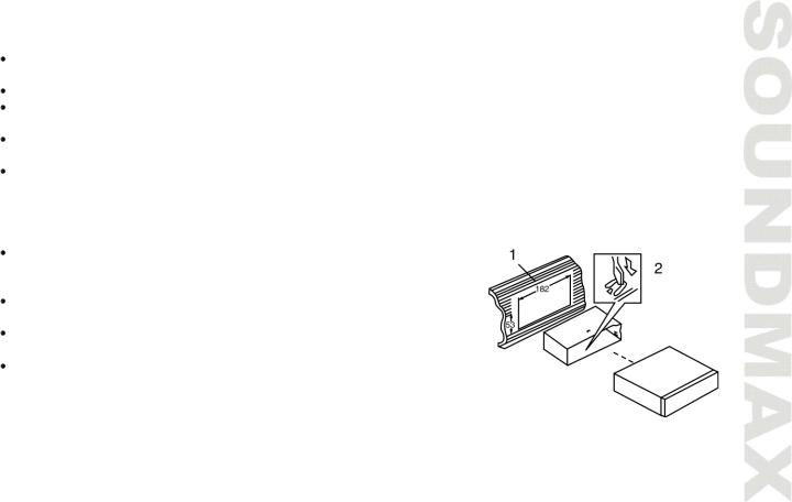
DIN front-mount (Method A)
Install the sleeve into the dashboard; ensure it is installed with the correct side and there are no obstacles (wires, dashboard elements, etc) for the unit installation.
After installing the sleeve into the dashboard, bend tabs fitting to the size of the dashboard to fix the sleeve in place.
Make the necessary wire connections. Ensure the connections are correct.
Install the unit into the sleeve until the side locks are fixed.
1.Dash board
2.Sleeve tab to bend
5
Trim frame installation
To install the trim frame, press it to the unit body and push it to fix it in place. This should be done before installing the front panel; otherwise you are not able to install the trim frame. When the trim frame being installed, the side with the groove should face down and fixed first.
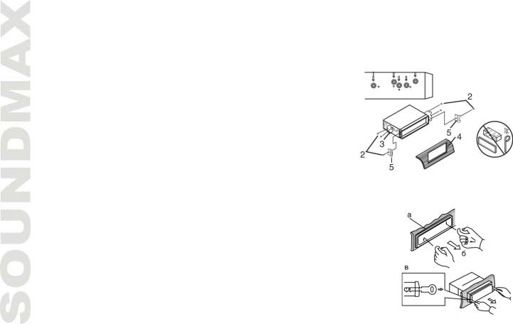
2. DIN rear-mount (Method B)
For this method, use the screw holes in the lateral sides of the unit. Fix the unit with the help of the factory radio mounting brackets.
1.Select a position in which the screw holes of the brackets (3) are aligned with the screw holes in the unit body, and screw in two screws
(2) in each side.
2.Screw.
3.Factory radio mounting brackets.
4.Vehicle dashboard.
5.Lock (remove this part).
Note: The outer trim frame and mounting sleeve are not used for method of installation.
Dismantling the unit
а – Trim frame
б – Frame uninstall direction в – Release key insertion
1.Switch off the unit and detach the front panel.
2.Insert your fingers into the groove in the front side of the trim frame (apply some effort to detach the frame). Pull the frame to detach it.
3.Insert the supplied release keys into the both sides of the unit body to click, as shown in the picture. To extract the unit from the dashboard, pull the release keys or the unit body to pull it out. Before detaching the unit, ensure it is not fixed with the metal strap.
6

Installing the front panel
Insert the right side of the panel then, and insert the left side. Lift the upper part of the panel and press it until a click to close the panel.
Press OPEN button to detach the panel. When the front panel is flipped-down, lift it to a little angle from horizontal position, then push the panel leftwards to release the right part. Then release the left part and pull the panel out.
Anti-theft system
The front panel of this unit can be stored in the included protective case when not in used and carried away when you leave the vehicle to deter theft.
Switch off the power of the unit. Detach the front panel, then put it to the protective case and take it with you.
Cautions: The control panel can easily be damaged by shocks. After removing it, place it in a protective case and be careful not to drop it or subject it to strong shocks.
The rear connector that connects the main unit and the control panel is an extremely important part. Be careful not to damage it by pressing on it with fingernails, pens, screwdrivers, etc.
Note: If the control panel is dirty, wipe off the dirt with soft, dry cloth only. And use a cotton swab soaked in isopropyl alcohol to clean the socket on the back of the control panel.
7

Connection diagram
Notes:
In spite of having any kinds of speaker system, must use 4 ohms impedance of speaker to reduce the distortion during high volume level.
It is prohibited making the conductors of auto antenna and ground touch with each other.
8

Using the ISO Connector
1.If your car is equipped with the ISO connector, then connect the ISO connectors as illustrated.
2.For connections without the ISO connectors, check the wiring in the vehicle carefully before connecting, incorrect connection may cause serious damage to this unit.
Cut the connector, connect the colored leads of the power cord to the car battery as shown in the colour code table below for speaker and power cable connections.
Location |
|
Function |
|
|
Connector A |
|
Connector B |
1 |
- |
|
Rear Right(+)---Violet |
2 |
- |
|
Rear Right(-)---Violet/Black stripe |
3 |
- |
|
Front Right(+)---Grey |
4 |
Battery 12V (+)/yellow |
|
Front Right(-)---Grey/Black stripe |
5 |
Auto Antenna/blue |
|
Front Left(+)---White |
6 |
- |
|
Front Left((-)---White/Black stripe |
7 |
Ignition/red |
|
Rear Left(+)---Green |
8 |
Ground/black |
|
Rear Left(-)---Green/Black Stripe |
Power antenna wire is intended for power supply of the antenna and for remote control of an additional amplifier.
9
Control elements
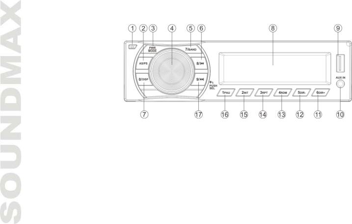
Front panel
1.OPEN ( ) button
2.AS/PS button
3.PWR/MODE button
4.SELECT button/VOLUME regulator
5.7/BAND button
6.8/ 
 button
7.0/DSP button
8.Display
9.USB port
10.AUX in jack
11.6 DIR+ button
12.5 DIRbutton
13.4 RDM button
14.3 RPT button
15.2 INT button
16.1 PAU button
17.9/
 button
10
Inner panel
Press OPEN button on the front panel to detach it.
18.RESET button (hole)
19.SD card slot
Pressing RESET hole will erase the clock setting and stored stations.
LCD layout
1, 3. Audio format indicators 2. CLASSIC equalizer mode
4.Loudness indicator
5.POP equalizer mode
6.Local station indicator
7.ROCK equalizer mode
8.Intro playback indicator
9.Random playback indicator
10.USB connection indicator
11.Repeat playback indicator
12.SD card indicator
13.Stereo reception indicator
14.Digits display
11
 Loading...