

Page 1
60&&5)
USB/SD media player USB/SD-медиаплеер
Instruction manual Руководство по эксплуатации
Page 2

2
Thank you for purchasing our product. For safety, it is strongly recommended to read this manual carefully
before connecting, operating and/or adjusting the product and keep the manual for reference in the future.
Dear customer!
Table of contents
TABLE OF CONTENTS......................................................................................................................................................2
IMPORTANT SAFEGUARDS............................................................................................................................................ 3
ACCESSORIES....................................................................................................................................................................4
INSTALLATION/CONNECTION...................................................................................................................................... 5
CONTROL ELEMENTS.......................................................................................................................................................9
GENERAL OPERATIONS.................................................................................................................................................. 10
RADIO OPERATIONS........................................................................................................................................................12
USB/SD OPERATIONS.....................................................................................................................................................13
TROUBLESHOOTING GUIDE..........................................................................................................................................15
SPECIFICATION .................................................................................................................................................................16
Page 3

3
Important safeguards
Read carefully through this manual to familiarize yourself with this high-quality sound system.
The beginning of oper ation is the moment of the uni t installation. Before use t he device in winter it is
recommended to heat up the passenger compartment during 20 seconds or to the operation temperature.
Use the unit with the temperature that goes beyond the operation temperature greatly decreases the
operation resource of the screen and other components of device and can result an outage.
Disconnect the vehicle's negative battery terminal while mounting and connecting the unit.
When replacing the fuse, be sure to use one with an identical amperage rating. Using a fuse with a higher
amperage rating may cause serious damage to the unit.
Make sure that pins or o ther for eign obje cts do not g et inside the unit; the y may cause ma lfunctions, or
create safety hazards such as electrical shock.
Do not use the unit in places where it can be exposed to water, moisture and dust.
Do not open covers and do not repair yourself. Consult the dealer or an experienced technician for help.
Make sure you disconnect the power supply and aerial if you will n ot be u s in g the sy stem f or a long period
or during a thunderstorm.
Make sure you disconnect the power supply if the system appears to be working incorrectly, is making an
unusual sound, has a str ange smell, has smoke emitting fro m it or liquids have got inside it. Have a
qualified technician check the system.
The unit is designed for neg ative termi nal of the batt ery, which is conne cted to t he vehi cle metal. Ple ase
confirm it before installation.
Do not allow the speaker wires to be shorted together when the unit is switched on. Otherwise it may
overload or burn out the power amplifier.
Page 4

4
Accessories
1. Receiver 1 pc
2. Mounting parts:
Hexagon nut 1 pc
Mounting sleeve 1 pc
Release keys 2 pcs
Metal bar 1 pc
Plain washer 1 pc
Spring washer 1 pc
Self-tapping screw 1 pc
Screw 4 pc
3. ISO-connector 2 pcs
4. 1 pc
Instruction manual
Page 5

5
Installation/Connection
General notes
Choose the mounting location where the unit will not interfere with the normal driving function of the
driver.
Before finally installing the unit, conn ect the wiring and make sure that the unit works properly.
Consult with your nearest dealer if installation requires the drilling of holes or other modifications of the
vehicle.
Install the unit where it does not get in the driver's way and cannot injure the passenger if there is a
sudden stop, like an emergency stop.
Avoid installing the unit where it woul d be subject to hig h temperature, s uch as from direc t sunlight, or
from hot air, from the heater, or where it would be subject to dust, dirt or excessive vibration.
DIN FRONT-MOUNT
1. Car dashboard
2. Sleeve
3. Bolt
4. Nut
5. Spring washer
6. Screw
7. Metal strap
8. Flat washer
1. Install the sleeve into the dashboard; ensure it is installed with the correct side and there are no
obstacles (wires, dashboard elements, etc) for the unit installation.
2. After installing the sleeve into the dashboard, bend tabs fitting to the size of the dashboard to fix the
sleeve in place.
3. Use the metal strap to fix the rear side of the unit. Determine a place for fixing and install the strap as
shown in the picture. You can bend the strap to the needed angle with y ou r hands.
Page 6
6
4. Make the necessary wire connections. Ensure the connections are correct.
5. Install the unit into the sleeve until the side locks are fixed.
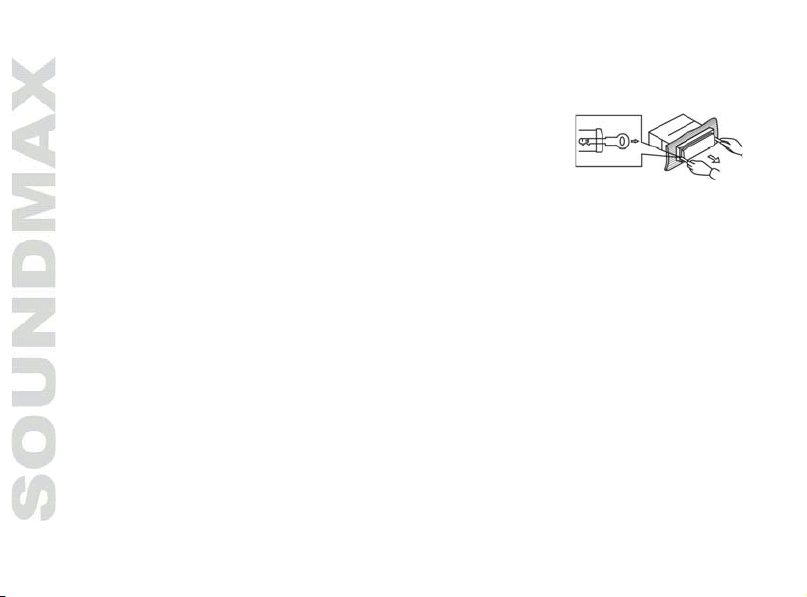
Dismantling the unit
1. Make sure the ignition is turned off, then disconnect the cable from the
vehicle battery’s negative (-) terminal.
2. Remove the metal strap attached the back of the unit (if attached).
3. Insert both of the supplied keys into the slots at the middle left and right
sides of the unit, then pull the unit out of th e dashboard.
Page 7
7
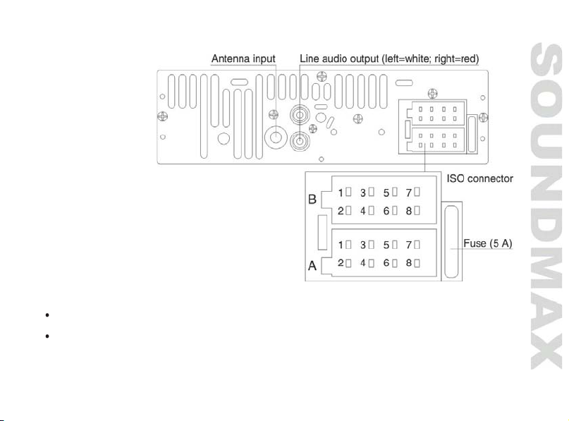
Connection diagram
Notes:
In spite of having any kinds of speaker system, must use 4 ohms impedance of speaker to reduce the
distortion during high volume level.
It is prohibited making the conductors of auto antenna and ground touch with each other.
Page 8
8
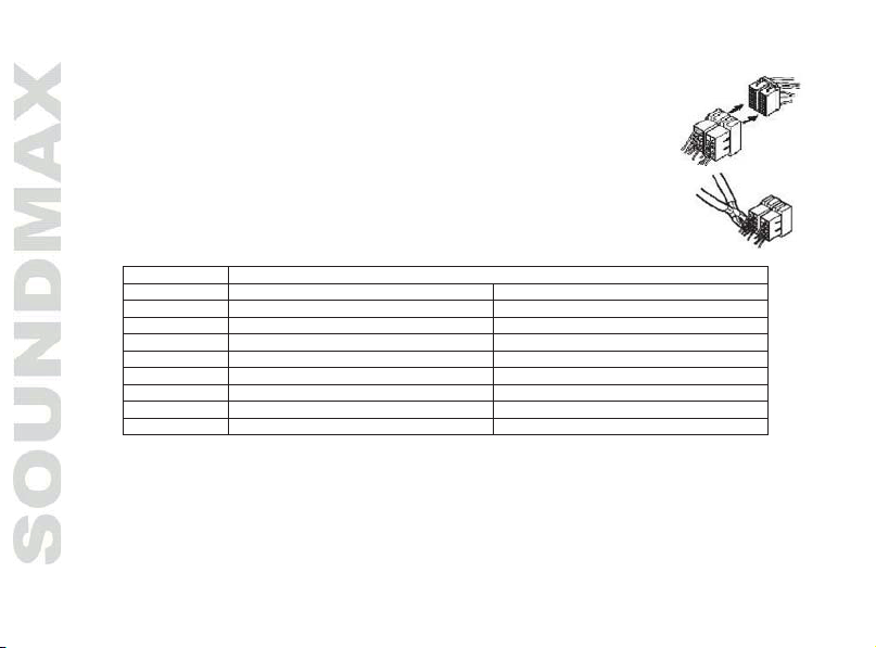
Using the ISO Connector
Location
Function
Connector A
Connector B
1 - Rear Right (+)---Violet
2 - Rear Right (-)---Violet/Black
3 - Front Right (+)---Grey
4
Battery 12V (+)/Yellow
Front Right (-)---Grey/Black
5
Auto Antenna/Blue
Front Left (+)---White
6 - Front Left (-)---White/Black
7
Ignition/Red
Rear Left (+)---Green
8
Ground/Black
Rear Left (-)---Green/Black
1. If your car is equipped with the ISO connector, then connect the ISO connectors as
illustrated.
2. For connections without the ISO connectors, check the wiring in the vehicle carefully
before connecting, incorrect connection may cause serious damage to this unit.
Cut the connector, connect the colored leads of the power cord to the car battery as
shown in the table below for speaker and power cable connections.
Power antenna wire is intended for power supply of the antenna and for remote control of an additional
amplifier.
Page 9
9
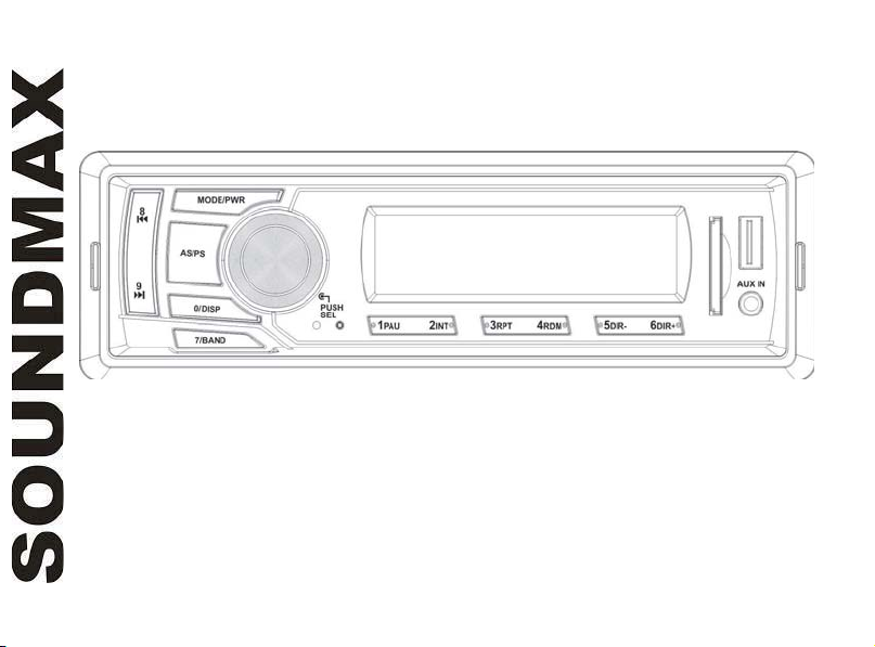
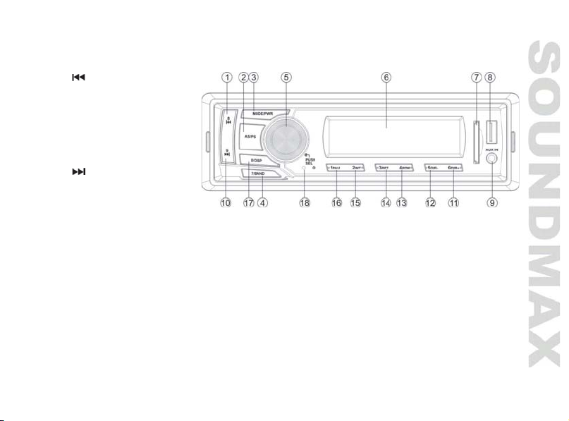
Control elements
Front panel
1. 8/
2. AS/PS button
3. MODE/PWR button
4. 7/BAND button
5. SEL button/VOLUME regulator
6. Display
7. SD slot
8. USB port
9. AUX IN jack
10. 9/
11. 6 DIR+ button
12. 5 DIR- button
13. 4 RDM button
14. 3 RPT button
15. 2 INT button
16. 1 PAU button
17. 0/DISP button
18. RESET button (hole)
button
button
Page 10
10
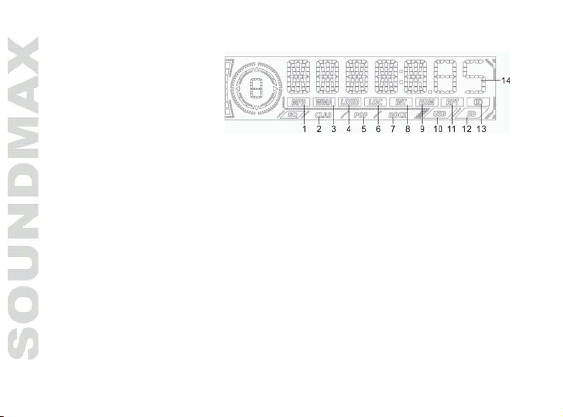
LCD layout
1, 3. Audio format indicators
2. CLASSIC equalizer mode
4. Loudness indicator
5. POP equalizer mode
6. Local station indicator
7. ROCK equalizer mode
8. Intro playback indicator
9. Random playback indicator
10. USB connection indicator
11. Repeat playback indicator The picture of LCD layout is for reference only and may differ
12. SD card indicator from the real-life layout.
13. Stereo reception indicator
14. Digits display
General operations
Power button
Press MODE/PWR button on the panel to switch the unit on. Press and hold this button to switch the unit off.
Volume control
Rotate VOLUME regulator to adjust volume level.
Audio settings adjustment
Press SELECT button shortly and repeatedly to select an option: BAS (bass) => TRE (treble) => BAL
(balance) => FAD (fader) => LOUD (loudness) => EQ (equalizer) => DX (distance) => STEREO/MONO =>
LOC (local) => VOL (volume). Rotate VOLUME regulator to adjust bass, treble, balance or fader.
Note: When equalizer is on, bass and treble adjustment is not av ailable.
Caution: In each mode, the waiting time is several seconds, and when the waiting time is over, it returns to
the last display mode of radio or playback mode.
Page 11

11
Mode selection
Press MODE/PWR button to choose a sound source: RADIO => USB => Memory card => AUX. USB and
memory card modes are available only when the storage is connected to this unit.
Clock adjustment
Press and hold 0/DISP button to go to clock adjustment mode. Hour digits will blink. Rotate VOLUME
regulator to adjust hours. Press SELECT button to go to mi nute adjustment; mi nute digits will b link. Rotate
VOLUME regulator to adjust minutes. Press DISP button to confirm clock setting. In any mode press shortly
DISP button to display the clock.
Equalizer setting
Press SELECT button shortly and repeatedly until EQ OFF (POP/CLASS/ROCK) is displayed. Rotate VOLUME
regulator to choose between sound effects: POP => CLASSIC => ROCK => EQ OFF.
Loudness control
Press SELECT button shortly and repeatedly until LOUD is displayed. Rotate VOLUME regulator to set loudness
on (LOUD indicator is displayed) or off (loudness indicator is not displayed). Loudness function is to
emphasize the bass output.
Reset function
Reset button (hole) is pressed with either a ballpoint pen or thin metal object. Reset function is to be
activated for the following reasons:
Initial installation of the unit when all wiring is completed.
All the function buttons do not operate.
Error symbol on the display.
AUX in jack
AUX-in jack is intended for co nnecting external audio equipment to am plify the so und. If connecti on is made
correctly, the audio signal from the external source will be translated through the acoustics of the head unit.
This enables to adjust the volume and quality of the sounding. For example, you can connect an MP3-player
to listen to tracks using the car acoustic system.
Page 12
12
Radio operations
Band selection
Press repeatedly 7/BAND button to select your desired radio band in radio mode: FM1, FM2, FM3. Each band
can store up to 6 preset stations, for the total of 18 preset memory stations.
Tuning
Auto tuning: Press 8/ or 9/ button; the unit will automatically search the nearest station with a
strong signal down or up the range and it stops when finds a station. To search next station, repeat this
procedure. To stop the automatical search, press 8/
Manual tuning: Press and hold 8/ or 9/ button until MANUAL is displayed. Then press 8/ /9/
buttons to change the frequency manually step by step.
Automatic store/Scan
Automatic store: Press and hold AS/PS button, the receiver will automatically find and save 6 strong
signal stations for the current subband.
Scan: Press AS/PS button once to scan the saved stations in each subband.
Programming stations
There are 6 numbered preset buttons (1~6), under which you can store and recall stations for each band.
Select the needed station, then press and hold a preset button. The station will be saved in the memory
under the corresponding number. To recall a stored station, press the corresponding preset button.
Mono/Stereo control (in FM radio mode)
Press repeatedly SELECT button until t he display shows STEREO (MONO). Rota te VOLUME regulator to select
between STEREO or MONO. STEREO means stereo reception of the signal; MONO means mono recepti on mo de.
Improvement of reception of distant stations can be done by selecting mono mode, which may cut down some
reception noise.
Local radio station
Press repeatedly SELECT button until the display shows LOCAL (DX). Rotate VOLUME regulator to select
between LOCAL or DX. LOCAL means that only local stations are received; DX means that both local and
distant stations with weak and strong signal are received.
or 9/ button.
Page 13

13
USB/SD operations
SD card slot
Carefully insert the SD card into the card slot on the front panel. Unit starts playback automatically. To
disconnect the memory card, press it until a click, and then carefully pull it out from the slot.
USB port
Carefully connect a USB driver to the USB jack on the front panel. Unit starts playback automatically.
USB/SD notes
USB format supports 2.0. Capacity: up to GB. SD cards capacity: up to GB. Supported file systems are
FAT/FAT32.
Note: Because of the great variety of products with SD-card slots and their sometimes quite manufacturerspecific functions the producer can neither guarantee that all devices will be recognized nor that all operating
options that are possible in theory will actually work. Before disconnecting a storage, switch the unit to
another mode.
Next/Previous track
Press 9/
playback or backward playback; release the button to return to normal playback.
Play/Pause
Press 1 PAU button to pause the playback, press one more time to resume normal playback.
Intro playback
When 2 INT button is pressed, the first several seconds of each track on the storage is played. INT indicator
will be displayed. Press again to stop intro and listen to track.
Repeat playback
When 3 RPT button is pressed, playback of the selected track will be continually repeated and RPT indicator
will be displayed until the track repeat mode is cancelled by pressing 3 RPT button again.
or 8/ buttons to choose next or previous track. Press and hold this button to choose forward
Page 14

14
Random
When 4 RDM button is pressed, each track on the storage is played in random instead of normal order. RDM
indicator will be displayed. To cancel Random mode, press 4 RDM button again.
Folder selection
Press 5 DIR- button to select previous folder. Press 6 DIR+ button to select next folder.
Track selection by number
Press AS/PS to go to track search mode. The *** will be displayed. Press number buttons (0~9) to input the
number of the needed track. Or rotate VOLUME regulator to select figures of the track number. Press SELECT
button to start playback of the selected track.
Page 15

15
Troubleshooting guide
Symptom
Cause
Solution
No power
Wiring is connected incorrectly.
Make correct wiring connection.
The car ignition is not on.
If the power supply is properly connected to
the car accessory, switch the ignition on.
The fuse is blown.
Replace the fuse.
No sound
Volume is in minimum.
Adjust volume to the desired level.
Wiring is not properly connected.
Check wiring connection.
The radio does not
work
The antenna cable is not
connected.
Insert the antenna cable properly.
The radio station
automatic tuning does
not work
The signals are too weak.
Select stations manually.
Below is a table describing simple measures that can help you eliminate mos t pr oblems likely to emerge when
this unit is in use. If below measures do not help, turn to a service center or to the nearest dealer.
Cleaning the unit body
Wipe with a soft cloth. If the cabinet is very dampen (not dropping wet) the cloth with a weak solution of
soapy water, and then wipe clean.
Page 16

16
Specifications
General
Power supply
12 V DC
Current consumption
<5 A
4 x 45 W
Unit dimensions
178 x 50 x 97 mm
Gross/Net weight
0.59 kg/0.36 kg
FM stereo radio
Frequency range
87.5 - 108.0 MHz
I.F. Frequency
10.7 MHz
Preset stations
18
Player
Supported storages
USB/SD
Frequency response
20 Hz – 18 КHz
Signal to noise
>66 dB
Line out
Stereo output RCA (2 V)
Output power
Specifications are subject to change without notice. Dimensions are approximate.
Page 17

17
Благодарим Вас за покупку нашего изделия. Для обеспечения безопасности рекомендуется тщательно
изучить настоящее руководство перед подключением, эксплуатацией и/или регулировкой изделия, и
сохраняйте руководство для использования в будущем.
Уважаемый покупатель!
Содержание
СОДЕРЖАНИЕ ....................................................................................................................................................................17
МЕРЫ ПРЕДОСТОРОЖНОСТИ......................................................................................................................................18
КОМПЛЕКТ ПОСТАВКИ .................................................................................................................................................. 19
УСТАНОВКА/ПОДКЛЮЧЕНИЕ......................................................................................................................................20
ЭЛЕМЕНТЫ УПРАВЛЕНИЯ.............................................................................................................................................24
ОБЩИЕ ОПЕРАЦИИ .........................................................................................................................................................25
ОПЕРАЦИИ С РАДИО ......................................................................................................................................................27
ОПЕРАЦИИ С USB/КАРТАМИ ПАМЯТИ SD .............................................................................................................29
РУКОВОДСТВО ПО УСТРАНЕНИЮ НЕИСПРАВНОСТЕЙ .....................................................................................31
ТЕХНИЧЕСКИЕ ХАРАКТЕРИСТИКИ ............................................................................................................................ 32
Page 18

18
Меры предосторожности
Тщательно изучите настоящую инструкцию, чтобы ознакомиться с устройством.
Началом эксплуатации устройства считается момент его установки в автомобиль. Перед началом
использования устройства в зимний период рекомендуется прогреть салон автомобиля в течение 20
минут или до достижения эксплуатационного диапазона температуры устройства.
Использование устройства при температуре, выходящей за рамки эксплуатационного диапазона
температур, значительно снижает ресурс работы экрана и других компонентов устройства и может
привести к выходу устройства из строя.
При установке и подключении устройства отключите отрицательную клемму аккумулятора
автомобиля.
При замене предохранителя убедитесь, что вы устанавливаете предохранитель с тем же номиналом.
Используя предохранитель с повышенным значением тока, можно причинить значительные
повреждения устройству.
Не используйте устройство в местах, где оно может подвергнуться воздействию воды, влаги и пыли.
Убедитесь, что шпильки или другие посторонние предметы не попали внутрь устройства. Они могут
вызвать сбои в работе или стать причиной опасности или возгорания.
Не открывайте крышки и не проводите ремонт устройства самостоятельно. Обратитесь к дилеру или
квалифицированному персоналу
Убедитесь, вы отключили источник питания и антенну, если вы не будете пользоваться устройством
в течение длительного времени или во время грозы.
Убедитесь, что вы отключили источник питания, если обнаружена неправильная работа системы,
система издает необычные звуки, запах, выделяет дым или внутрь ее попала жидкость. Проведите
квалифицированный технический осмотр системы.
Устройство разработано таким образом, чтобы отрицательный вывод аккумулятора был подключен к
корпусу транспортного средства. Пожалуйста, убедитесь в этом перед установкой.
Не позволяйте проводам динамиков касаться друг друга или корпуса автомобиля после включения
устройства. В противном случае может быть перегружен или выйти из строя усилитель.
Page 19

19
Комплект поставки
1. Ресивер 1 шт
2. Детали для установки:
Шестигранная гайка 1 шт
Кожух 1 шт
Ключи-съемники 2 шт
Металлическая пластина 1 шт
Пружинная шайба 1 шт
Плоская шайба 1 шт
Винт-саморез 1 шт
Винт 4 шт
3. ISO-коннектор 2 шт
4. 1 шт
Руководство по эксплуатации
Page 20

20
Установка/Подключение
Общая информация
Перед окончательной установкой устройства временно подключите все провода и убедитесь, что все
соединения выполнены верно, а устройство и система работают правильно.
Для обеспечения правильной установки устройства используйте только те детали, которые входят в
комплект. Использование других приспособлений может привести к появлению сбоев в его работе.
Если для установки устройства необходимо сверлить отверстия в кузове автомобиля или вносить
какие-либо другие изменения в его конструкцию, проконсультируйтесь с продавцом.
Устанавливайте устройство там, где оно не будет закрывать водителю обзор и отвлекать от
дорожной обстановки и не сможет нанести травм пассажирам в случае внезапной остановки
автомобиля, например, при экстренном торможении.
Никогда не устанавливайте устройство в таких местах, где оно будет подвергаться воздействию
высокой температуры, например, в местах попадания прямых солнечных лучей, в местах выхода
горячего воздуха от отопителя автомобиля, в местах, где очень грязно или пыльно, или там, где
устройство будет подвергаться сильной вибрации.
Перед установкой устройства обязательно снимите переднюю панель.
Установка устройства в приборную панель автомобиля «спереди»
Установка устройства
1. Приборная панель автомобиля
2. Монтажный кожух
3. Винт
4. Гайка
5. Пружинная шайба
6. Винт
7. Опорная планка.
8. Плоская шайба
Page 21

21
1. Установите монтажный кожух в приборную панель автомобиля, убедитесь, что он установлен
правильной стороной и нет препятствий (провода, элементы приборной панели) для установки
магнитолы.
2. После установки монтажного кожуха в приборную панель отогните на нем металлические язычки,
соответствующие толщине приборной панели. Это позволит закрепить кожух на месте.
3. Обязательно используйте металлическую пластину для
Определите место крепления и установите ее согласно приведенному рисунку. Пластину можно
согнуть руками под нужным углом.
4. Подключите необходимые провода и разъемы. Убедитесь в правильности подключения.
5. Установите магнитолу в монтажный кожух до фиксации боковых защелок.
закрепления задней стороны проигрывателя.
Снятие устройства
1. Убедитесь, что зажигание отключено, затем отсоедините провод от
отрицательной (-) клеммы
2. Удалите металлическую пластину, с помощью которой корпус
устройства зафиксирован сзади.
3. Вставьте оба ключа-съемника в прорези на правой и левой сторонах
фронтальной части декоративной рамки устройства, затем, держась за
ключи, вытяните устройство на себя из приборной панели.
аккумулятора.
Page 22

22
Схема подключения
Примечания:
Независимо от вида динамиков следует использовать динамики с сопротивлением, равным 4 Ом, для
уменьшения искажений при повышенной громкости.
Запрещается соединять провода авто антенны и заземления между собой.
Page 23

23
Использование разъема ISO
Номер
Функция
Разъем A
Разъем B
1 - Задний правый (+)/---Фиолетовый
2 - Задний правый (-)/---Фиолетовый/Черный
3 - Передний правый (+)/---Серый
4
Питание 12В (+)/Желтый
Передний правый (-)---Серый/Черный
5
Питание антенны/Синий
Передний левый (+)---Белый
6 - Передний левый (-)---Белый/Черный
7
Зажигание/Красный
Задний левый (+)---Зеленый
8
Заземление/Черный
Задний левый (-)---Зеленый/Черный
1. Если в Вашем автомобиле есть разъем ISO, произведите подключение, как
показано на рисунке.
2. Для подключений без разъемов ISO внимательно проверьте все провода перед
подключением, неправильное подключение может привести к повреждениям
изделия. Обрежьте разъем, подключите головки разъема к шнуру питания батареи
в соответствии с приведенной таблицей.
Провод питания антенны предназначен для подачи питания на антенну и для удаленного управления
дополнительным усилителем.
Page 24
24
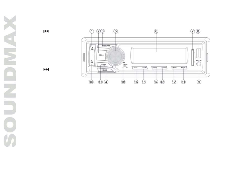
Элементы управления
Передняя панель
1. Кнопка 8/
2. Кнопка AS/PS
3. Кнопка MODE/PWR
4. Кнопка 7/BAND
5. Кнопка SEL/регулятор VOL
6. Дисплей
7. Отверстие для карты SD
8. USB-порт
9. Разъем AUX IN
10. Кнопка 9/
11. Кнопка 6 DIR+
12. Кнопка 5 DIR-
13. Кнопка 4 RDM
14. Кнопка 3 RPT
15. Кнопка 2 INT
16. Кнопка 1 PAU
17. Кнопка 0/DISP
18. Кнопка (отверстие) RESET
Page 25

25
LCD дисплей
1, 3. Индикатор формата аудио
2. Режим эквалайзера CLASSIC
4. Индикатор громкости
5. Режим эквалайзера POP
6. Режим локальных
радиостанций
7. Режим эквалайзера ROCK
8. Индикатор режима
предпрослушивания
9. Индикатор режима воспроизведения
в произвольном порядке
10. Индикатор подсоединения USB-носителя
11. Индикатор режима повторного воспроизведения
12. Индикатор карты памяти SD
13. Индикатор приема стереосигнала Внешний вид символов дисплея может отличаться от
14. Цифровой дисплей приведенного вы
только для наглядности.
ше изображения, которое служит
Общие операции
Включение устройства
Нажмите кнопку MODE/PWR на панели, чтобы включить устройство. Нажмите и удерживайте эту кнопку,
чтобы отключить питание устройства.
Регулирование уровня громкости
Вращайте регулятор VOLUME, чтобы отрегулировать уровень громкости звука.
Регулировка параметров аудио
Нажимайте кнопку SELECT на передней панели, чтобы выбрать параметр: BAS (низкие частоты) => TRB
(высокие частоты) => BAL (баланс между левыми/правыми динам
задними/передними динамиками) => LOUD (громкость) => EQ (эквалайзер) => DX (дистанция) =>
иками) => FAD (баланс между
Page 26

26
STEREO/MONO => LOC (местные радиостанции) => VOL (уровень звука). Вращайте регулятор VOLUME,
чтобы отрегулировать уровень низких, высоких частот или баланс между динамиками.
Примечание: При включенном эквалайзере регулирование высоких и низких частот невозможно.
Внимание: Каждая настройка отображается на дисплее в течение нескольких секунд. Если в течение
этого времени ни одна кнопка не была нажата, дисплей
Выбор режима
Нажимайте кнопку MODE/PWR, чтобы выбрать режим работы устройства: Радио => USB => Карта
памяти => AUX. Режимы USB и карты памяти доступны, только если соответствующий накопитель
установлен в разъем данного устройства.
Тонкомпенсация
Нажимайте кнопку SELECT до отображения на дисплее LOUD. Вращайте регулятор VOLUME для
включения (индикатор LOUD отображается на дисплее)
отображается) функции тонкомпенсации. Также для включения или отключения этой функции вы
можете нажимать и удерживать кнопку 7/BAND. Данная функция полезна, если вы хотите уменьшить
уровень звука без потери четкости звучания.
Настройка часов
Нажмите и удерживайте кнопку DISP для перехода к настройке часов. Цифры, обозначающие часы,
будут мигать.
перехода к настройке минут; цифры, означающие минуты, будут мигать. Вращайте регулятор VOLUME,
чтобы настроить минуты. Нажмите кнопку DISP, чтобы подтвердить настройку часов. В любом режиме
нажмите кратко кнопку DISP для отображения на дисплее часов.
Выбор режима эквалайзера
Нажимайте кнопку SELECT до отображения на дисплее
VOLUME для выбора режима эквалайзера: POP => CLASSIC => ROC => E Q O FF (выкл).
Функция сброса
Кнопку (отверстие) сброса следует нажимать тонким металлическим предметом (например, шариковой
ручкой). Функция сброса используется в следующих случаях:
Вращайте регулятор VOLUME, чтобы настроить часы. Нажмите кнопку SELECT для
вернется в обычный режим.
или отключения (индикатор LOUD не
EQ OFF (POP/CLASS/ROCK). Вращайте регулятор
Page 27
27
Начало работы с устройством, после его подключения.
Кнопки устройства не работают.
На дисплее отображается символ ошибки.
Вход AUX
Разъем AUX предназначен для подключения внешнего аудиоустройства с целью усиления звука. В
случае правильного подключения аудиосигнал от внешнего источника будет транслироваться через
акустику головного устройства. Это дает возможность регулировать громкость и качество звучания.
Например, Вы можете подключить MP3-проигрыватель для прослушивания аудиозаписей через акустику
автомобиля.
Операции с радио
Выбор диапазона
Нажимайте кнопку BAND, чтобы выбрать диапазон в режиме радио: FM1, FM2, FM3. В каждом диапазоне
можно сохранить до 6 радиостанций, общее количество сохраняемых радиостанций составляет 18.
Настройка радио
Автоматическая настройка: Нажмите кнопку 8/ или 9/ ; устройство автоматически выполнит
поиск ближайшей радиостанции с сильным сигналом вниз или вверх по диапазону. При
обнаружении станции поиск остановится. Повторите операцию для поиска следующей станции.
Чтобы прервать автопоиск, нажмите кнопку 8/
Ручная настройка: Нажмите и удерживайте кнопку 8/ или 9/ до отображения на дисплее слова
MANUAL. Нажимайте кнопки 8/
Автоматическое сохранение/Сканирование
Автоматическое сканирование и сохранение: Нажмите и удерживайте кнопку AS/PS; приемник
автоматически выполнит сканирование текущего поддиапазона и сохранит 6 станции с сильным
сигналом.
Сканирование: Нажмите кнопку AS/PS, приемник выполнит сканирование сохраненных станций в
каждом поддиапазоне.
/9/ для пошагового изменения частоты.
или 9/ .
Page 28

28
Сохранение и вызов радиостанций
На панели устройства есть кнопки с цифрами (от 1 до 6), с помощью которых Вы можете сохранять и
включать радиостанции в каждом диапазоне. Выберите нужную радиостанцию, затем нажмите и
удерживайте кнопку с цифрой. Станция будет сохранена в памяти устройства под этой цифрой. Для
вызова сохраненной станции нажмите соответствующую
Моно/стерео прием (для FM радио)
Нажимайте кнопку SELECT до отображения на дисплее надписи STEREO (MONO). Вращайте регулятор
VOLUME, чтобы включить режим приема стерео (STEREO) или моно (MONO). Достичь улучшения
дистанционного сигнала можно, включив режим моно, что позволяет убрать лишние звуковые шумы.
Поиск локальных радиостанций
Нажимайте кнопку SELECT до отображения на дисплее надписи LOCAL (DX). Вращайте регулятор
VOLUME для переключения между LOCAL (активация приема местных радиостанций со слабым сигналом)
и DX (отключение приема местных радиостанций; прием удаленных радиостанций как со слабым, так и
с сильным сигналом).
кнопку с цифрой.
Page 29

29
Операции с USB/картами памяти SD
Загрузка карт памяти SD
Вставьте SD-карту в соответствующий слот, расположенный на передней панели. Начнется
воспроизведение первого трека. Для отсоединения карты памяти нажмите на нее до щелчка, затем
извлеките карту из слота.
USB-порт
Вставьте USB-носитель в USB порт, расположенный на передней панели. Автоматически начнется
воспроизведение первого трека.
Информация по USB/SD разъемам
USB: Поддержка формата USB 2.0. Емкость: до ГБ. SD: Емкость: до ГБ. Устройством поддерживается
файловые системы FAT/FAT32.
Примечание: устройство может не воспроизодить некоторые модели USB-накопителей и карт памяти.
Используйте только лицензионные накопители известных брендов. Перед извлечением накопителя из
слота устройства переключите устройство в другой режим работы.
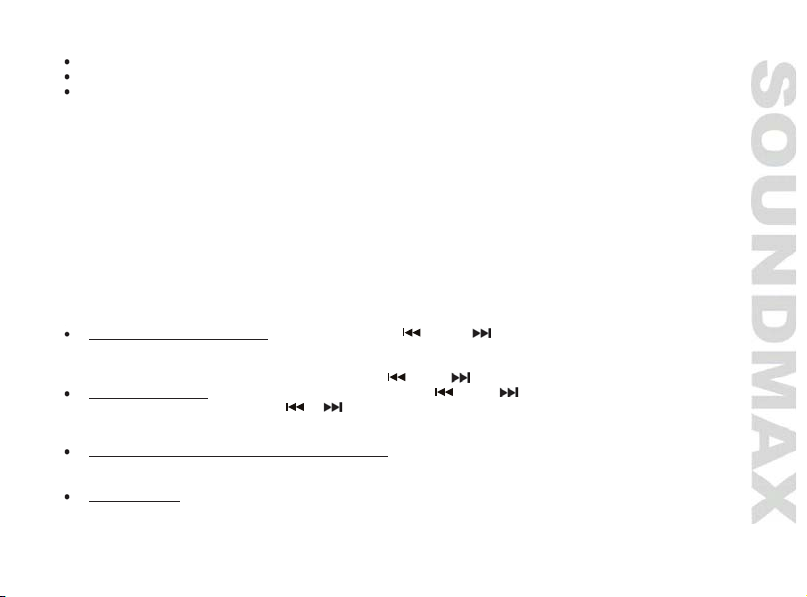
Выбор трека
Нажмите кнопку
удерживайте эту кнопку, чтобы начать ускоренное воспроизведение трека вперед или назад; отпустите
кнопку для возврата к нормальному воспроизведению.
Пауза
Нажмите кнопку 1 PAU, чтобы поставить воспроизведение на паузу; нажмите кнопку еще раз, чтобы
возобновить воспроизведение.
Предпрослушивание
Во время воспроизведения нажмите кнопку 2 INT,
секунд каждого трека. На дисплее отобразится индикатор обзорного воспроизведения INT. Нажмите эту
кнопку еще раз, чтобы вернуться в нормальный режим воспроизведения.
9/ или 8/ , чтобы выбрать следующий или предыдущий трек. Нажмите и
чтобы началось проигрывание первых нескольких
Page 30

30
Повтор
Нажмите кнопку 3 RPT, активируется режим повтора воспроизведения текущего трека. На дисплее
отобразится индикатор повторного воспроизведения RPT. Нажмите эту кнопку еще раз, чтобы вернуться
в режим нормального воспроизведения.
Воспроизведение в произвольном порядке
Нажмите кнопку 4 RDM, активируется режим воспроизведения треков в произвольном порядке. На
дисплее отобразится индикатор случайного воспроизведения RDM. Нажмите эту
вернуться в режим нормального воспроизведения.
Выбор папки
Во время воспроизведения нажимайте кнопки 5 DIR- или 6 DIR+ для перехода к предыдущей или
следующей папке соответственно.
Выбор трека по номеру
Нажмите кнопку AS/PS для перехода к поиску треков. На дисплее отобразится надпись TRKSCH, затем
***. Нажимайте кнопки с цифрами (0~9), либо вращайте
нужного трека. Нажмите кнопку SELECT для запуска воспроизведения выбранного трека.
регулятор VOLUME, чтобы ввести номер
кнопку еще раз, чтобы
Page 31
31
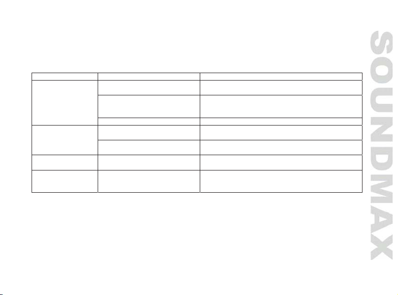
Руководство по устранению неисправностей
Неисправность
Причина
Решение
Нет питания
Неправильно подсоединены
провода.
Выполните подсоединение электропроводки
правильно.
Зажигание машины не
Если источник питания подключен надлежащим
ключ зажигания в положение “АСС”.
Предохранитель сгорел.
Замените предохранитель.
Нет звука
Громкость звука установлена
на минимум.
Отрегулируйте громкость звука до
необходимого уровня.
Неправильно подсоединены
провода.
Выполните подсоединение электропроводки
правильно.
Радиоприемник не
работает
Кабель антенны не
подключен к устройству.
Подключите к устройству кабель антенны.
Не работает
радиостанций
Радиостанции имеют
Настраивайтесь на станции вручную.
Ниже приводится таблица, в которой описаны простые проверки, способные помочь Вам устранить
большую часть проблем, могущих возникнуть при использовании данного устройства. Если
нижеуказанные меры не помогли, обратитесь в сервисный центр или к ближайшему дилеру.
включено.
автонастройка
Чистка корпуса устройства
Протирайте поверхности устройства мягкой тканью. Не мочите корпус. Если корпус очень загрязнен,
используйте ткань, слегка смоченную мыльным раствором, и затем вытрите корпус сухой тканью.
слишком слабый сигнал.
образом к выключателю машины, установите
Page 32

Технические характеристики
Общие
Источник питания
12 В, постоянный ток
Потребляемый ток
Не более 5 А
4 х 45 Вт
Размеры
178 x 50 x 97 мм
Вес брутто/нетто
0,59 кг/0,36 кг
Стерео FM радио
Частотный диапазон
87,5 – 108,0 МГц
Промежуточная частота
10,7 МГц
Память
Проигрыватель
Поддерживаемые носители
USB/SD
Частотный диапазон
20 Гц – 18 КГц
Отношение сигнал-шум
66 дБ
Линейный выход
Стереоаудиовыход RCA (2 В)
Выходная мощность
SM-CCR3076F_T-0156_IM_02
Произведено:
Произведено: Куианянг Трейдинг Компани Лимитед № 89 Юи Джин Роад, Джиангмен Гуангдонг, Китай
Под контролем «ТЕХНО ЭЛЕКТРИК ЛИМИТЕД»
Изго товитель: «ТЕХНО ЭЛЕКТРИК ЛИМИТЕД»
Сделано в Китае
СЕРТИФИКАТ СООТВЕТСТВИЯ:
RU C-CN.АЛ16.В.13511
Срок действия с 01.08.2016, по 31.07.2019 включительно
18 станций
Уполномоченная организация:
ООО "ТрейдХоум" РФ, 117105, г. Москва, Варшавское ш., д.39, комната 1(603), тел.:+7 (916) 441-57-14,
email: support@trdhm.ru
Месяц и год изготовления нанесены на стикере баркода на упаковке и на гарантийном талоне
в формате MM.ГГ, где ММ – месяц изготовления, а ГГ – поледние две цифры года изготовления.
32
Page 33

Безопасная утилизация
Ваше устройство спроектировано и изготовлено из высококачественных материалов и
компонентов, которые можно утилизировать и использовать повторно. Если товар имеет
символ с зачеркнутым мусорным ящиком на колесах, это означает, что товар соответствует
Европейской директиве 2002/96/ЕС. Ознакомьтесь с местной системой раздельного сбора
электрических и электронных товаров. Соблюдайте местные правила. Утилизируйте старые
устройства отдельно от бытовых отходов. Правильная утилизация вашего товара позволит
предотвратить возможные отрицательные последствия для окружающей среды и
человеческого здоровья.
Хранение и транспортировка
Упакованные изделия допускается транспортировать всеми видами транспорта в условиях
5 ГОСТ 15150 при температуре не ниже минус 10 °С и при защите их от прямого воздействия
атмосферных осадков и механических повреждений. Изделия следует хранить в условиях
1 по ГОСТ 15150 при отсутствии в воздухе кислотных, щелочных и других агрессивных примесей.
При транспортировании и хранении упакованные изделия должны быть уложены в штабели,
контейнеры или стеллажи. Количество рядов в штабелях должно быть установлено в зависимости
от габаритных размеров и массы упакованных изделий и указано в ТУ на изделие
конкретной модели.
Page 34

Page 35

Page 36
Page 37
 Loading...