

Page 1
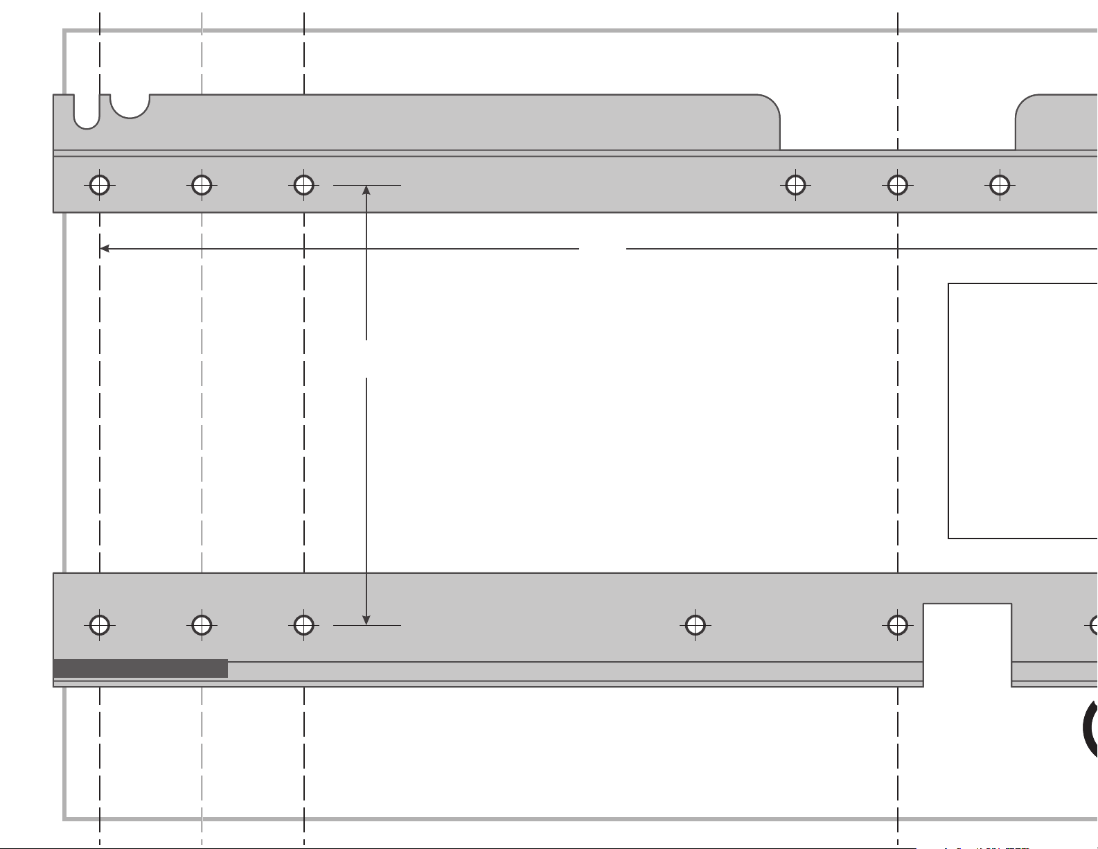
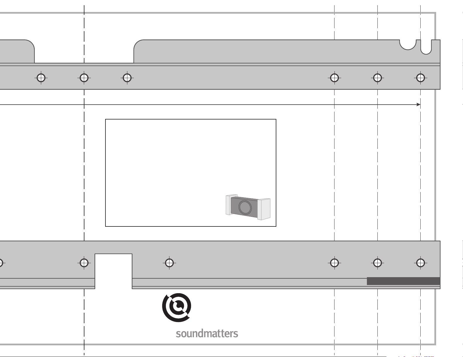
4.4”
16.0”
Upper Bracket
Lower Bracket
Rubber Bushing Rubber Bushing
Note: When mounted, the top edge of the SUBstage will be
about 9/16” above the top edge of the upper bracket.
SUBstage 250/100
Wall-Mount Screw Hole Template
for SSWB1 Mounting Bracket Kit
IMPORTANT WARNING: This bracket assembly MUST be
screwed solidly into wooden studs. Use this bracket ONLY if
you can screw into wooden studs.
WARNING: Make sure all pictures/etc. are well secured to
the wall as they may vibrate loose and rattle.
Pro Tuning Tip: Listen and tweak the settings for crossover,
volume and phase BEFORE nal wall-mounting. Use the foam
end caps from the packaging to temporarily wedge the unit
into approximate position behind a chair
or sofa. Note, once unit is wall-mounted,
it will have to be UN-mounted to change
these settings
Note: When mounted, the bottom edge of the
SUBstage will be about 1-5/16” below the bottom
edge of the lower bracket.
Page 2
IMPORTANT WARNING: This bracket assembly MUST be
screwed solidly into wooden studs. Use this bracket ONLY if
you can screw into wooden studs.
WARNING: Make sure all pictures/etc. are well secured to
the wall as they may vibrate loose and rattle.
Pro Tuning Tip: Listen and tweak the settings for crossover,
volume and phase BEFORE nal wall-mounting. Use the foam
end caps from the packaging to temporarily wedge the unit
into approximate position behind a chair
or sofa. Note, once unit is wall-mounted,
it will have to be UN-mounted to change
these settings
soundmatters international
tel: 775 981.1460
fax: 775 981.1465
www.soundmatters.com
Page 3

SUBstage 250/100 Wall-Mount Instructions for SSWB1 Mounting Bracket Kit
Read this before you begin
IMPORTANT: Because the SUBstage generates a tremendous
amount of low-frequency energy, this bracket assembly MUST
be screwed solidly into wooden studs. It is NOT sucient
to screw into metal studs, nor only into plaster or drywall.
(Obviously, screwing through the wall surface and into studs
is the right thing.) Using buttery-style or other anchors in
drywall will NOT keep the bracket secure for long, and are most
denitely NOT suitable. The bottom line: use this bracket ONLY if
you can screw into wooden studs.
Read through all the instructions and look at the illustrations
before you begin. Having a good overview will make the
project proceed more smoothly and the nal installation will be
professional quality.
Contents
1 Upper Bracket
1 Lower Bracket with attached Rubber Bushings
4 Bolts 1/4-20 x 3/8”
4 Washers 3/16”
1 J-hook (left side)
1 J-hook (right side)
4 Deck Screws (8 ga x 3”)
1 Instruction Sheet
1 Template Sheet
Tools needed
• Stud nder (do NOT attempt to install this bracket if it cannot be
securely attached to wooden studs with two screws per bracket)
• Drill and drill bit (1/8” or smaller for pilot holes)
• Phillips screwdriver
• 11mm (preferred) or 7/16” open-end wrench
• Level
• Pencil and tape
A. Mount Hardware on Substage
1. Unscrew and remove the four feet.
2. In their places: on top, screw in bolt and washer
with about 3/16” space); then, on bottom, screw in bolt,
washer and J-hook (tighten rmly).
(leave loose
B. Align Template on Wall
1. Use stud nder. Carefully nd centers of
appropriate studs, then lightly mark position on wall in pencil. (Typically, studs in
residences are on 16” centers. The outermost holes on the wall-mountbrackets are
exactly 16” apart. What a coincidence!)
2. Tape template to wall at the
desired mounting height,
carefully aligning two top
holes and two bottom holes
with the centers of studs.
Be sure template diagram
is level. Use vertical dashed
lines to align template to
centerline of studs.
Use a stud nder to nd the studs, then use vertical
lines on template to carefully align holes with studs.
3. Drill a thin pilot hole (1/16”–1/8” dia) through the upper left
position. If drill successfully hits wood stud, proceed to drill
lower left. Drill each hole into wood about 1 “.
4. Now go to upper right position and drill pilot hole there that
will hit a stud. If successful, proceed to lower right pilot hole.
Drill each hole into wood about 1 “.
5. Remove template from wall.
C. Mount Brackets To Wall
1. Using the pilot holes you
D. Plug In Cables, Make Settings,
Give It a Test Listen, Tweak
1. Securely plug-in source interconnect and right-angle AC cord.
Turn on power switch because it may be dicult to get to it
once unit is mounted on the wall. (It’s always okay to leave
the unit powered on all the time.) Make sure your settings are
where you want them before you proceed to next step.
Pro tuning tip: Listen and tweak the settings for crossover, volume and phase
BEFORE nal wall-mounting. Use the foam end caps from the packaging to
temporarily wedge the unit into approximate position
behind a chair or sofa. Note, once unit is wall-mounted,
it will have to be UN-mounted to change these settings
E. Hang It, then Secure It
1. Make sure the cables are routed down the back and will align
with the cutouts in the brackets
2. See the illustrations below. To “hang” the SUBstage on the
brackets, hold the unit about an inch directly above the
brackets, then move it straight down so the lower J-hooks
catch on the rubber-bushing-covered lower lip, and simul-
taneously the two upper bolts slip into the slots of the upper
bracket. The washers should be between the bolt heads and
the bracket.
Page 4

(leave loose
desired mounting height,
carefully aligning two top
holes and two bottom holes
with the centers of studs.
Be sure template diagram
is level. Use vertical dashed
lines to align template to
centerline of studs.
3. Drill a thin pilot hole (1/16”–1/8” dia) through the upper left
position. If drill successfully hits wood stud, proceed to drill
lower left. Drill each hole into wood about 1 “.
4. Now go to upper right position and drill pilot hole there that
will hit a stud. If successful, proceed to lower right pilot hole.
Drill each hole into wood about 1 “.
5. Remove template from wall.
C. Mount Brackets To Wall
1. Using the pilot holes you
drilled, mount brackets using
the deck screws provided. At
least 2” of screw thread should
enter the wood of the stud.
Tighten rmly, but do not overtighten.
D. Plug In Cables, Make Settings,
Give It a Test Listen, Tweak
1. Securely plug-in source interconnect and right-angle AC cord.
Turn on power switch because it may be dicult to get to it
once unit is mounted on the wall. (It’s always okay to leave
the unit powered on all the time.) Make sure your settings are
where you want them before you proceed to next step.
Pro tuning tip: Listen and tweak the settings for crossover, volume and phase
BEFORE nal wall-mounting. Use the foam end caps from the packaging to
temporarily wedge the unit into approximate position
behind a chair or sofa. Note, once unit is wall-mounted,
it will have to be UN-mounted to change these settings
E. Hang It, then Secure It
1. Make sure the cables are routed down the back and will align
with the cutouts in the brackets
2. See the illustrations below. To “hang” the SUBstage on the
brackets, hold the unit about an inch directly above the
brackets, then move it straight down so the lower J-hooks
catch on the rubber-bushing-covered lower lip, and simultaneously the two upper bolts slip into the slots of the upper
bracket. The washers should be between the bolt heads and
the bracket.
3. When you are sure you’ve gotten it properly and securely
located (that is, both J-hooks on botton rail and both top
bolts completely inserted in their notches), use an 11mm
(or 7/16”) open-end wrench to tighten the top bolts
until tight. (As you are facing the SUBstage, tighten them
counterclockwise)
4. Ta-da, congratulations! Time to enjoy the fruits of your labor.
Plug in source interconnect, plug in AC, get down, get funky,
get low…enjoy that acoustic rubdown!
NOTE: When mounted correctly, there will be no rattles or
buzzes coming from the SUBstage, even at full throttle. BUT,
keep in mind that the powerful subwoofer is now mechanically
coupled to your wall. While this increases the amount of bass in
the room (a wonderful thing!), it may cause other things on
the wall to vibrate (say, picture frames, for example). If so,
secure them to the wall.
Move unit directly over the wall
brackets, then slide down into place
Final step: rmly tighten both
top bolts using 11mm or 7/16”
open-end wrench
On top: Bolt slips into
slot on bracket.
On bottom: J-hook
should catch on lip.
soundmatters international
tel: 775 981.1460
fax: 775 981.1465
www.soundmatters.com
 Loading...