

Page 1

SERIES 10
USER GUIDE
Page 2

© Soundcraft Electronics Ltd. 1992, 1993
All rights reserved
Parts of the design of this product may be protected by worldwide patents.
Issue 2
Part No. ZM0004
Information in this manual is subject to change without notice and does not
represent a commitment on the part of the vendor. Soundcraft Electronics Ltd.
shall not be liable for any loss or damage whatsoever arising from the use of
information or any error contained in this manual.
No part of this manual may be reproduced, stored in a retrieval system, or
transmitted, in any form or by any means, electronic, electrical, mechanical,
optical, chemical, including photocopying and re co rd ing, fo r a ny purpose
without the express written permission of Soundcraft Electronics Ltd.
It is recommended that all maintenance and servic e on th e produ ct should be
carried out by Soundcraft Electronics Ltd. or its authorised agents. Soundcraft
Electronics Ltd. cannot accept any liability whatsoever for any loss or dama ge
caused by service, maintenance or repair by unauthorised personnel.
Soundcraft Electronics Ltd.
Cranborne House,
Cranborne Road,
Cranborne Industrial Estate,
Potters Bar,
Herts.,
England.
EN6 3JN.
Tel: 0707 665000
Fax: 0707 660482
Page 3

&RQWHQWV
Introduction 1
Introduction 2
Precautions and Safety Instructions 4
Block Diagrams 7
Mono Input Module 8
Telco Input Module 8
Stereo Input Module 8
Master/Monitor Section 9
Applications 11
Connections and Connectors 12
Mono Input Channel 13
Telco Input Channel 15
Stereo Input Channel 17
Master Section 19
Monitor Section 20
Meterbridge 21
Mono Input Channel 23
Description and Operation 24
Specifications 26
Telco Channel 27
Description and Operation 28
Specifications 30
Page 4

Stereo Input Channel 31
Description and Operation 32
Specifications 34
Master Section 35
Description and Operation 36
Specifications 38
Monitor Section 39
Description and Operation 40
Appendices 45
Glossary 46
Dimensions 47
Warranty 48
Page 5

Introduction
Introduction
Precautions and Safety Instructions
Introduction to the MBI Series 10 1
Page 6

,QWURGXFWLRQ
The Series 10 is a fully modular mixing console for local radio stations and smaller
self-operated studios of national broadcasters. The system has been designed to
accommodate the individual requirements of a station by providing flexibility and
a choice of configurations.
The Series 10 is available in a 24 module-width frame with a capacity of 20 input
channels (12 if fitted with a script space, the script space is 8 modules wide; or 14
if a 6-modules-width script blank is fitted) and a 32 module-width frame where
more input channels are required. Note that the script tray is a dished compartment
whereas the script blank is a flat plate on the same plane as the console panel.
Three types of input module are available:
Mono Input Module
Each module may be used for Mic/Line inputs. The module can be supplied with
or without a 3-band fixed frequency EQ section.
Telco (Telephone Communication) module
In addition to outputting signals to the programme, each module provides for on
and off-air telephone conversations with the Presenter, Guests or Producer. The
module can be supplied with or without a 3-band fixed frequency EQ section.
Stereo Module
Each module accepts one of two switch-se lectable stereo sources. One is the normal
source, such as a CD player or cart. machine, which is hard wired to the multipin
connector. The other may be an alternative or te mporary source which is connected
via XLR connectors. There are also connections for the remote operation of Start
& Stop relays for both of the sources. The module can be supplied with or without
a 3-band fixed frequency EQ section.
All inputs are fitted with peak signal detection to a lert the operator to any impending
headroom problems which could cause unwanted distortion.
Remote Controls
Remote controls are provided for cue lights and also ’on-air’ lights for local and
distant mics, and there are remote controls for cough muting and talkback routing.
Remotes are provided for telephone hybrid control and for on-board talkback to
cleanfeed. Off-air communication with the Caller can be set up from the Ope rato r
or the Producer. Stereo and mono modules (in line mode) have remote outputs fo r
machine start and stop/re-cue.
2 Introduction to the MBI Series 10
Page 7

Master and Monitor Module
There are two variants of the Master and Monitor module: the Production variant
has the optional main Programme Faders and Effects Returns, the Broadcast version
has neither. The Master and Monitor module also contains the auxiliary master
level control; monitoring controls, for Presenter’s headphones and loudspeakers,
Studio headphones and loudspeakers; and communica tio ns inpu ts.
Module Options
Mono Input Module with EQ . . . S10ME
Mono Input Module without EQ . S10M
Stereo Input Module with EQ . . S10SE
Stereo Input Module without EQ . S10S
Telco Module with EQ . . . . . . S10TE
Telco Module without EQ . . . S10T
Production Master/Monitor . . . S10OP
(with faders and effects returns)
Broadcast Master/Monitor . . . S10OB
(without faders or effects returns)
The Meterhood
The meterhood conceals studio wiring and provides space for additional
monitoring, loudspeakers, clock.timer,talkback and meter units.
It is equipped, as standard, with LED Master Meters. The fo llowing are o ptionally
available:
Large VU Master Meters
Single Large VU Meter
Small VU Meters
Large PPM Master Meters
Single Large PPM Meter
Small PPM Meters
RTW Bargraph Meter
PFL/Talkback Loudspeaker Module
Talkback Remote Module
Timer Module
Input Selector
Power Supply
The Series 10 requires a CPS150 power supply. This is available with an optional
rack-mount front panel.
Introduction to the MBI Series 10 3
Page 8

3UHFDXWLRQVDQG6DIHW\,QVWUXFWLRQV
General Precautions
Caution!
Handling and Transport
Power supplies & cables
Avoid storing or using the console in conditions of excessive heat or cold, or in
positions where it is likely to be subject to vibration, dust or moisture. Do not use
any liquids to clean the fascia of the unit: a soft dry brush is ideal. Use only water
or ethyl alcohol to clean the trim and scribble strips. Other solvents may cause
damage to paint or plastic parts.
Avoid using the console close to strong sources of electromagnetic radiation (e.g.
video monitors, high power electric cabling): this may cause degradation of the
audio quality due to induced voltages in connecting leads and chassis. For the same
reason, always site the console power supply away from the unit .
In all cases, refer servicing to qualified personnel.
The console is a very rugged unit, designed for long service. However, care in
handling and transportation will ensure a long and trouble-free life. If the console
is to be regularly moved we recommend that it is installed in a foam lined flight
case. At all times avoid applying excessive force to any knobs, switches or
connectors.
Always make sure that the power supplies have been set to the same source voltage
as the mains supply.
Warning!
Always use the power supplies and power cables supplied with the console: the use
of alternative supplies may cause damage and voids the warranty; the extension of
power cables may result in malfunction of the console.
Always switch the power supplies off before connecting or
disconnecting the console power cable, removing or installing
modules, and servicing. In the event of an electrical storm, or large
mains voltage fluctuations, immediately switch off the PSU and
unplug from the mains.
Always ensure that that you use the correct power supply for your console. Each
Series 10 console requires the CPS150 power supply.
4 Introduction to the MBI Series 10
Page 9

Signal Levels
It is important to supply the correct input levels to the console, otherwise
signal-to-noise ratio or distortion performance may be degraded; and in extreme
cases damage to the internal circuitry may result. Likewise, on all balanced inp uts
avoid sources with large common mode DC, AC or RF voltages, as these will reduce
the available signal range on the inputs. Note that 0dBu = 0.775V RMS.
The microphone input is designed for use with balanced low impedance
(150 or 200Ω) microphones.
Caution!
DO NOT use unbalanced microphones or battery powered
condenser microphones without isolating the +48V phantom power
- degraded performance or damage to the microphone may result.
Introduction to the MBI Series 10 5
Page 10

6 Introduction to the MBI Series 10
Page 11

Block Diagrams
Mono Input Module
Telco Input Module
Stereo Input Module
Master/Monitor Module
Block Diagrams 7
Page 12

Block Diagrams
Mono Input Module
Telco Input Module
Stereo Input Module
Master/Monitor Module
Block Diagrams 7
Page 13

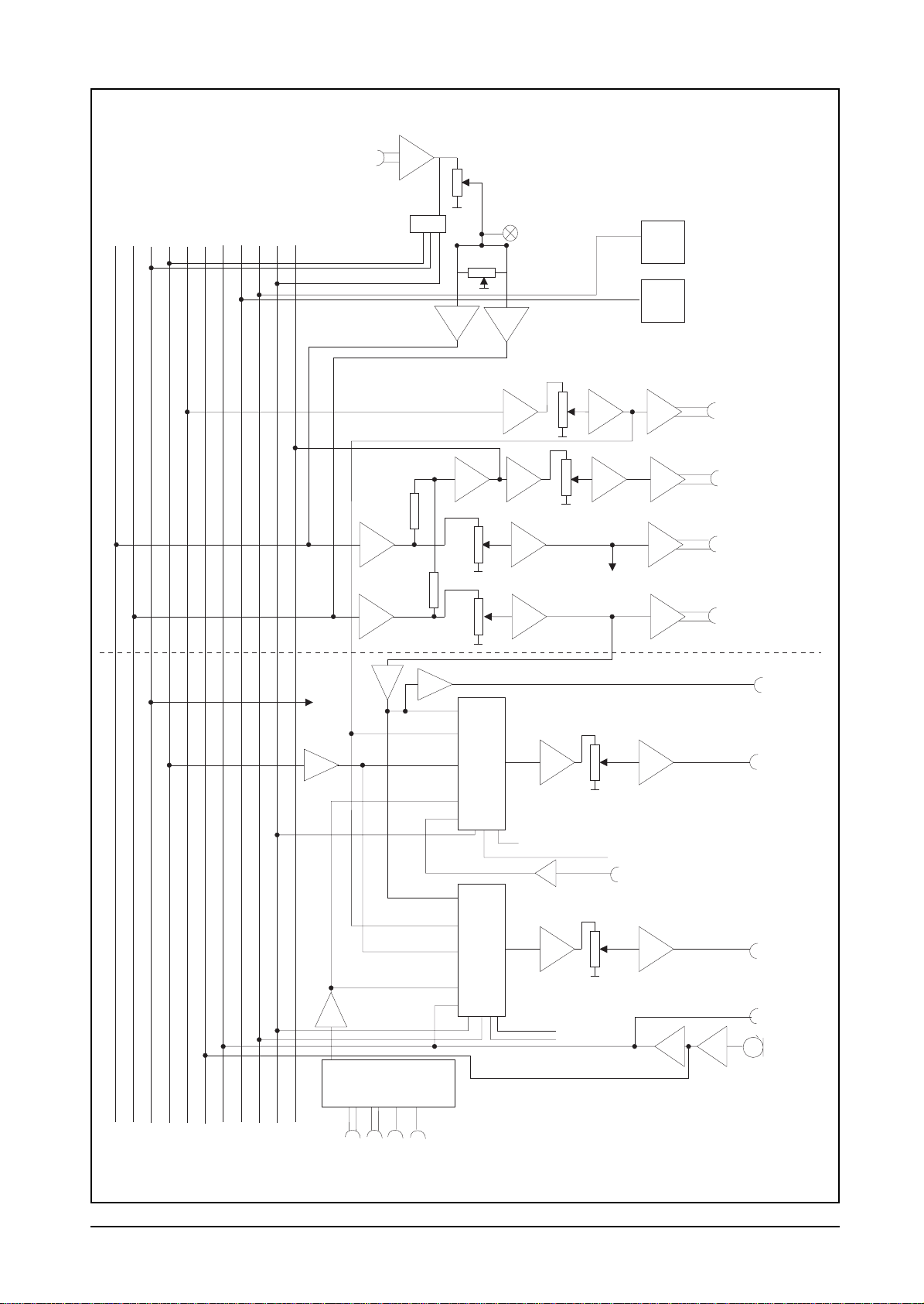
%ORFN'LDJUDPV
MONO INPUT CHANNEL
PGM
MIX
LR
PFL L
PFL R
AUX
LOCAL MUTE
TB MIX
DIST MUTE
PFL D.C.
MIC
LINE
48V
LINE
LINE
INSERT
+/-15dB TRIM
80Hz
HPF
+/-15dB TRIM
80Hz
HPF
TB ENABLE
REM
COUGH
PFL
COMM
EXT TB
PRE or
PEAK
OPT.
EQ
POST
FADER
TB CONTROL
REMOTE
LOGIC
TELCO INPUT CHANNEL
PEAK
OPT.
EQ
PFL
REMOTE
LOGIC
PFL CONTROL
CUE LIGHT
PRE or
POST
FADER
PFL CONTROL
PAN
INPUT 2 START
INPUT 2 STOP
/RE-CUE
AUX
PAN
AUX
COUGH
MUTE
PGM
MIX
LR
PFL L
PFL R
AUX
TB MIX
TB OUTPUT
LOCAL MUTE
DIST MUTE
PFL D.C.
MONO OUTPUT
CLEAN FEED
OUTPUT
LINE 1
LINE 2
Duplicate stereo
circuits not shown
for clarity.
LINE
80Hz
HPF
BALANCE
START
PFL
CLEAN
FEED
CONTROL
EXT TB
STEREO INPUT CHANNEL
PEAK
OPT.
EQ
+/-15dB TRIM
REMOTE
LOGIC
PRE or
POST
FADER
PFL CONTROL
INPUT 1 START
INPUT 1 STOP
/RE-CUE
INPUT 2 START
INPUT 2 STOP
/RE-CUE
AUX
PGM
MIX
LR
PFL L
PFL R
AUX
TB MIX
LOCAL MUTE
DIST MUTE
PFL D.C.
8 Block Diagrams
Page 14
PGM
MIX
LR
PFL L
PFL R
AUX MIX
TB MIX
LOCAL MUTE
DIST MUTE
TB OUTPUT
OPTIONAL
FX RETURN
X 2
PFL D.C.
MONO OUTPUT
PFL
FX LEVEL
PAN
MASTER/MONITOR SECTION
PEAK
AUX
MASTER
OPTIONAL
MONO FADER
DISTANT
MUTE
RELAY
LOCAL
MUTE
RELAY
AUX OUTPUT
MONO OUTPUT
LEFT OUTPUT
TO
SOURCE
SELECT
DESK
AUX
PFL
EXT
TB
DESK
AUX
PFL
EXT
TB
OPTIONAL
STEREO FADER
SOURCE
SELECT
SPLIT PFL
SOURCE
SELECT
TO SOURCE SELECT
STUDIO TB
AUTO PFL
LEVEL
CONTROL ROOM MONITOR
IS SIMILAR EXCEPT THAT IT
HAS AUTO PFL INSTEAD OF
SPLIT PFL.
IT ALSO HAS LOCAL MUTE.
TALKBACK LOGIC
TALKBACK
LEVEL
STUDIO HEADPHONES CIRCUIT
IS SIMILAR EXCEPT THAT IT
DOESN’T HAVE DISTANT MUTE.
RIGHT OUTPUT
STEREO OUT
PRES
HEADPHONES
TB I/P 1
TB I/P 2 NOT
SHOWN FOR CLARITY
STUDIO
MONITOR
CONTINUOUS
TB O/P
INBUILT MIC
EXT SELECTOR
ONLY THE RIGHT HAND SIDE OF STEREO SIGNALS
FOR MONITORS ARE SHOWN FOR CLARITY
1234
EXTERNAL INPUTS
Block Diagrams 9
Page 15

10 Block Diagrams
Page 16

Applications
Connections and Connectors
Mono Input Channel
Telco Input Channel
Stereo Input Channel
Master Section
Monitor Section
Meterbridge
Applications 11
Page 17

Applications
Connections and Connectors
Mono Input Channel
Telco Input Channel
Stereo Input Channel
Master Section
Monitor Section
Meterbridge
Applications 11
Page 18

Applications
This section is intended to help you to connect, to the console, the external
equipment which you need. It also identifies all of the user-definable options which
are available and gives the location of the links involved.
Connections And Connectors
Although this may seem to be a simple subject, faulty conn ectors and cabling are
the source of mos t sound s ystem prob lems. Correc tly-made cables of the proper
type will ensure peak performance from your console.
Three different types of co nnectors are used on your console: 3- pin XLR,
1
⁄4" 3-pole
jack sockets and D-type connectors. It is recommended that low-profile D-type
connectors are used: there is a risk that high-profile types may foul the backs of
meters etc. in the meterbridge.
Note: The Module Descriptions sections of this manual give details of the type and
gender of th e chassis mo unted connectors.
The following diagram shows details of the first two types.
1
/4" ‘A’ Gauge Stereo Jack Plug used as balanced outputs/inputs,
Aux and Effects Returns
1
/4" ‘A’ Gauge Stereo Jack Plug used for stereo outputs,
Headphones and Monitors
The following page s giv e de t ai ls of all of the connectors which a re not covered b y
the above diag ram.
12 Applications
Page 19

Mono Input Channel
REMOTES SOCKET (25-pin D-type female)
This socket provides for the following facilities:
Input 1 Cue Lamp
A relay switch closes between pins 12 & 13 of the Remotes socket when the
following conditions are all met:
The Mic input is selected, the REM button is depressed and the Fader is up.
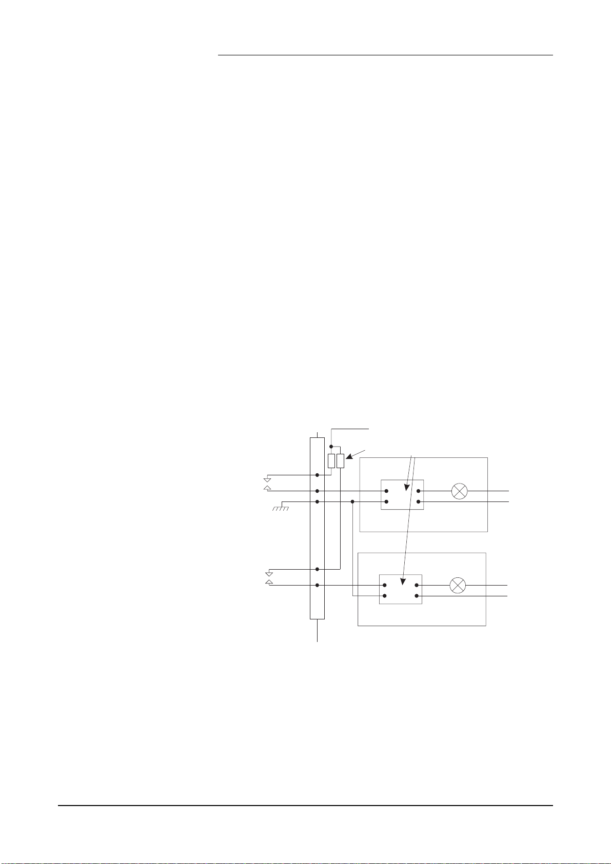
The following diagram shows one possible method of using this relay switch to
control a cue lamp. It is vital that mains voltages are NOT connected to any of the
connectors on the console.
Console
+16V
Remotes Skt
20
13
12
18
Current limiting
resistor
Opto-isolated
Solid-state
Relay
Cue-Lamp
Mains
N
L
E
Input 2 Start
A relay switch c loses betwee n pins 8 & 9 of the Remote s socket when the followi ng
conditions are all met:
The LINE input is selected, the REM button is depressed
and the Fader is up .
Note: The relay may be configured to pick momentarily or latch depending up on
link 6: if link 6 is present it causes the relay to latch.
Input 2 Stop/Re-Cue
A relay switch c loses mome ntaril y betwee n pins 6 & 7 of the Rem otes so cket whe n
the following conditions are all met:
The LINE input is selected, the REM button is released
and the Fader is do wn.
Talkback
Two pins on the Remotes socket are used for this feature, as follows:
Ground Pin 3
Talkback enable Pin 15
A switch may be con nected be tween pin s 15 & 3 . Whe n this sw itch is clos ed the
pre-fade input signal is fed to the T/B MIX bus. This would, for example, let a
Studio Guest talk off-air to a telephone Caller provided that the Talkback feature
on the Telco channel is also used.
Applications 13
Page 20

COUGH/REVERSE TALKBACK Switch
This user-provided facility has two functions, as follows:
1) The Input Channel is muted when all of the following conditions are met: The
Mic input is selected, the Fader is up and the Cough Switch is closed. This allows
the Presenter/Guest to temporarily mute his or her microphone.
2) The Cough Switch allows the Guest to force a PFL so that he or she may talk
to the Presenter. This forced PFL occurs when all of the following conditions are
met: The Mic input is selected, the Fader is
Two pins on the Remotes socket are used for this feature, as follows:
Ground Pin 2
Cough Pin 14
A switch may be connected between pins 14 & 2.
Insert Point (Send/Return)
Two pins on the Remotes socket are used for this feature, as follows:
Send Pin 22 Send 0V pin 21
Return Pin 23 Return 0V pin 18
You will need to remove link 5 from the pcb in order to use the insert Point.
down and the Cough Switch is closed.
Power Rails
The following power rails are available as follows:
+16V Pin 20 (supplied via a 10R current-limiting resistor)
-16V Pin 19 (supplied via a 10R current-limiting resistor)
0V audio Pins 18 and 21.
Options
Designating a channel as Local or Distant
Link 2 may be set to A for Local or to B for Distant. This will control which set of
speakers is muted when this channel is opened: if A is selected the Control Room
Monitor output will be muted, or if B is selected the Studio Monitor output will be
muted.
Aux - Pre-fade or Post-fade
The factory default for the Auxiliary Output on the Mono Input channel is pre-fade.
This may be altered to post-fade by moving link 3.
Phantom Power for Microphones
If Link 1 is in place then +48V will be present on pins 2 and 3 of the Mic XLR
connector. Phantom powered mics should not be plugged in with the +48V
switched on. You should also be aware that some mics draw an unusually large
current. The current for each mic is limited to 14mA by series resistors.
14 Applications
Page 21

Link Locations
The following outline diagram of the Mono Input Channel PCB shows the location
of the user-changeable links.
Link Locations on the Mono Input Channel PCB
LK 1
LK5
LK6
LK3
LK2
Telco Input Channel
The following diagram shows how a Telephone Hybrid may be connected to the
Telco Input Channel. A separate Hybrid for each Telco channel will be required.
From Divert Switch
To Telco Input
Hybrid
To Handset
REMOTES SOCKET (25-pin D-type female)
This socket provides for the following facilities:
From Clean FeedFrom Phone Line
Telephone Divert
The Divert Switch on Telco channel is a single-pole 2-way switch. Connections to
it are made available on the Remotes socket. The details are as follows:
Common Pin 12
Normally Closed Pin 13
Normally Open Pin 11
It will be necessary to consult the Hybrid manufacturer’s handbook in order to use
this switch to control the divert function of the Hybrid you are using. You may
have to devise a simple ’interface’ to utilise the divert function.
Talkback
Two pins on the Remotes socket are used for this feature, as follows:
Ground Pin 2
Talkback enable Pin 15
To use this feature you must connect a switch between pins 2 and 15. When the
switch is closed the telephone caller will hear a reduced programme output mixed
with the output of the T/B OUTPUT bus. This bus carries the signal from the inbuilt
desk mic plus the T /B MIX bus; the T/B MIX bus ca rrie s the pre- fade signals fro m
any of the Mono Input channels whose Talkback enable is also active.
If a 2-pole switch is used, the other contacts may be used to enable the Talkback
from a Mono Input Channel.
Applications 15
Page 22

Ext Talkback (logic)
Two pins on the Remotes socket are used for this feature, as follows:
Ground Pin 3
Talkback enable Pin 14
To use this feature you must connect a switch between pins 3 and 14. When the
switch is closed and the Telco channel Fader is down a PFL condition is forced (the
led in the PFL switch glows to indicate this); The pre-fade signal from the Telco
input is therefore placed on the PFL MIX L and R buses. In addition the Caller will
hear a reduced programme output mixed with the input to the External Talkback
input, see below.
Ext Talkback (audio)
This is an electronically balanced input.
Two pins, pins 24 and 25, on the Remotes s ocket are used for this feature.
The External Talkback (logic and audio) would normally be connected to a
custom-built Producer’s Unit. This would contain the switch to control the logic,
a mic and preamp to feed the audio input, and facilities for the producer to hear the
PFL MIX L & R buses. The PFL signals are available on the MISC socket of the
monitor section.
Options
Aux - Pre-fade or Post-fade
The factory default for the Auxiliary Output on the Telco channel is pre-fade. This
may be altered to post-fade by moving link 1. The location of this link is shown in
the following outline diagram of the Telco Channel PCB.
Link Locations on the Telco Input Channel PCB
LK 1
16 Applications
Page 23

Stereo Input Channel
LINE 1 + REMOTES SOCKET (25-pin D-type female)
This socket provides for the following facilities:
Input 1 Left
This input is electronically balanced. The input pins are as follows:
Hot (+ve) Pin 24
Cold (-ve) Pin 25
Input 1 Right
This input is electronically balanced. The input pins are as follows:
Hot (+ve) Pin 22
Cold (-ve) Pin 23
Input 1 Start Relay
A relay switch clo se s be t ween pins 12 & 13.
Input 2 Start Relay
A relay switch clo se s be t ween pins 9 & 8.
Link for Latching Start
If Link 6 is present the Start Relays will latch instead of closing momentarily.
Link 6 is located as shown in the diagram below.
Input 1 Stop/Re-cue Relay
A relay switch clo se s be t ween pins 11 & 10.
Input 2 Stop/Re-cue Relay
A relay switch clo se s be t ween pins 7 & 6.
Power Rails
The following power rails are available as follows:
+16V Pin 20 (supplied via a 10R current-limiting resistor)
-16V Pin 19 (supplied via a 10R current-limiting resistor)
0V audio Pins 18 and 21
Options
Aux - Pre-fade or Post-fade
The factory default for the Auxiliary Output on the Stereo Input channels is pre-fade.
This may be altered to post-fade by moving the links (3 and 4) which are located as
shown in the diagram below.
Links for +10dBv boost on input 2
If Links 1 and 2 are present the output of the preamps on Input 2 will be boosted by
10dBv. The links are located as shown in the following diagram.
Applications 17
Page 24

Link Locations
The following outline diagram of the Stereo Input Channel PCB shows the location
of the user-changeable links.
Link Locations on the Stereo Input Channel PCB
LK3
LK 1
LK2
LK6
LK4
18 Applications
Page 25
Master Section
Power Socket
The connections are as follows:
Pin 1 +17V
Pin 2 -17V
Pin 3 +48V
Pins 4, 5 and 6 tied together and to all grounds
REMOTES SOCKET (9-pin D-type male)
This socket provides for the following facilities:
Local Mute Relay
A 2-pole relay switch closes between pins 2 & 6, and pins 3 & 7. This relay could
be used to control an ’On-Air’ lamp in the Control-Room.
Distant Mute Relay
A 2-pole relay switch closes between pins 4 & 8, and pins 5 & 9. This relay could
be used to control an ’On-Air’ lamp in the Studio.
Pin 1 is a Ground connecti on .
The following diagram shows one possible method of using these relay switches to
control an ’On-Air’ lamp. It is vital that mains voltages are NOT connected to any
of the connectors on the console.
Console
Remotes Skt
2
6
1
4
8
Current limiting
resistors
Monitors Section
Talkback 1 and 2
The TB I/P 1 and 2 inputs are via
To Misc Skt Pin 14 (+16V)
Opto-isolated
Solid-state
Relay
Control-room
’On-air’
Lamp
Studio
’On-air’
Lamp
1
⁄
" 3-pole jack sockets. The connections are:
4
Mains
N
L
E
Mains
N
L
E
Sleeve Gnd
Ring Logic control (this is shorted to ground via a switch
to activate the Talkback circuit)
Tip An unbalanced audio input
Applications 19
Page 26

Continuous TB O/P
The connections are:
Tip Signal
Ring + Sleeve Ground
External Inputs Socket (15-pin D-type male)
The following balanced inputs are provided for:
External Input 1 Left+ Pin 2
External Input 1 Left- Pin 9
External Input 1 Right+ Pin 3
External Input 1 Right- Pin 10
External Input 2 Left+ Pin 4
External Input 2 Left- Pin 11
External Input 2 Right+ Pin 5
External Input 2 Right- Pin 12
The screen for all of these balanced inputs is pin 1.
The following unbalanced inputs are provided fo r:
External Input 3 Left Pin 7
External Input 3 Right Pin 8
External Input 4 Left Pin 14
External Input 4 Right Pin 15
The 0V for all of these unbalanced inputs is on pin s 6 an d 13 .
Misc Socket (15-pin D-type female)
This socket is used to drive the meterbridge modules.
Pin 1 Chass i s Gro un d
Pin 2 V- (-16V audio)
Pin 3 V+ (+16V audio)
Pin 4 Ref Grou nd
Pin 5 MFML (Meter Follows Monitor-Left)
Pin 6 MFMR (Meter Follows Monitor-Right)
Pin 7 PFL Li ne Left
Pin 8 PFL Line Right
Pin 9 Stere o Left (this is provide d fr om th e sa me source as the Stereo
Output Socket)
Pin 10 Stereo Right (t h i s i s pr ov ided from the same sou rc e as the S t er eo
Output Socket)
Pin 11 Local Mute (logic level signal, 0=local mute is active)
Pin 12 Talkback Output (a direct connection to T/B OUTPUT bus)
Pin 13 PFL Enable (logic level signal, 0=PFL is active)
Pin 14 +16V (Logic)
Pin 15 0V (Logic)
20 Applications
Page 27

Meterbridge
Wiring
The meterbridge is equipped with a distribution board, SC3357, to which the
meterbridge modules are connected. The optional meterbridge equipment (listed
below) can be user -connected to t his distribution boa rd via the wiring har ness which
is supplied with the optional equipment.
Options
The 24 module-width frame has space for 24 meterbridge-option widths and the 32
module-width frame has space for 32 meterbridge-option widths. Note that a
meterbridge-option width is not the same size as an input-module width: the
meterbridge-option width is slightly smaller in order to accommodate the edges of
the meterbridge frame.
The following options are available :
LED Master Meters (Std) . . . S10LED . 4MW (Meterbridge-Option Width)
Large VU Master Meters . . . S10VLR . 8MW
Single Large VU Meter . . . . S10V1 . 4MW
Small VU Meters . . . . . . . S10V2 . 4MW
Large PPM Master Meters . . S10PLR . 8MW
Single Large PPM Meter . . . S10P1 . 4MW
Small PPM Meters . . . . . . S10P2 . 4MW
RTW Panel (inc. loom
but excluding Meter) . . . . S10RTW . 8MW
PFL/TB Loudspeaker Mod ule S10MBS . 4MW
Talkback Remote Module . . . S10TB . 4MW
Double Meterbridge Blank . . S10MB8 . 8MW
Single Meterbridge Blank . . . S10MB4 . 4MW
Timer . . . . . . . . . . . . S10TIM . 4MW
Input Selector . . . . . . . . . S10SEL . 4MW
Meterbridge Distribution Board
The diagram for this PCB is shown overleaf. Fitting instructions are provided
with the optional Meterbridge Modules.
Installing Meterbridge Modules
1) Raise th e Meterbridge housing and secure in the raised position with the two
wingnuts.
2) Unscrew the blanking plate in the required location.
3) Mount and secure the module in the meterbridge.
4) Connect the module’s loom to the relevant connector.
5) Loosen the wingnuts and carefully lower the meterbridge.
Applications 21
Page 28

Meterbridge Distribution Board SC3357
22 Applications
Page 29

Mono Input Channel
Description & Operation
Specification
Mono Input Channel 23
Page 30

0RQR,QSXW&KDQQHO
1
Input Stage
2
1
when the
The
LINE INPUT
LINE
switch is depressed.
is via a standard female XLR-3 connector. It is available
10
11
12
13
14
3
2
the
3
4
5
6
7
8
9
This 25-way D-type connector allows you to implement the following facilities:
COUGH/REVERSE TALKBACK Switch
This user-provided facility has two functions, as follows:
1) The Input Channel is muted when all of the following conditions are met: The
Mic input is selected, the Fader is up and the Cough Switch is closed. This allows
the Presenter/Guest to temporarily mute his or her microphone.
2) The Cough Switch allows the Guest to force a PFL so that he or she may talk
to the Presenter. This forced PFL occurs when all of the following conditions are
met: The Mic input is selected, the Fader is
(see the Applications section).
CUE LAMP
This user-provided facility will be controlled via relay contacts which close when
all of the following conditions are met: The Mic input is selected, the Fader is up
and the REM switch is depressed (see the Applications section).
START RELAY
The contacts of this relay will close when all of the following conditions are met:
The Line input is selected, the REM switch is depressed and the Fader is up. The
relay contacts can either close momentarily or they may latch, depending upon
link 6 (see the Applications section).
STOP/RE-CUE RELAY
The contacts of this relay will close momentarily when the following c onditions are
met: The Line input is selected and the REM switch is relea sed and/or the Fad er is
down (see the Applications section).
MIC INPUT
The
LINE
REMOTES
is via a standard female XLR-3 connector. It is available when
switch is released.
Socket
down and the Cough Switch is closed
15
TALK-BACK SWITCH
This user-provided switch will, when closed, put the signal from the pre-fade section
of the circuit onto the T/B OUTPUT bus and also to the Continuous Talkback Output
socket of the Monitor section. The major use of this facility is th at the T/B OUTPUT
bus feeds the Telco Channels and will allo w the Presenter, Guest or Producer to talk
to a telephone Caller off-air (see the Applications section).
SEND/RETURN
This allows for the use of an effects machine to be added to the mo no input channel,
e.g. voice processor, echo. The send and return lines are unbalanced and ca re will
need to be taken with the length and type of leads which are used. This facility is
enabled by the removal of link 5 (see the Applications section).
24 Mono Input Channel
Page 31

4
Two
of the input sockets. They allow for the coarse a dju stmen t of input le ve ls.
COARSE ADJUSTMENT PRESET POTS
are available, one for each
The
LINE
switch selects the Line Input socket when depressed and the Mic
5
Input socket when released. A LED in the switch glows red when the Lin e Input is
selected.
Auxiliary Send
The
AUX
control routes the input channel signal onto the Auxiliary Mix bus.
6
The input channel signal may be fed to the Auxiliary control either pre-fade or
post-fade. The factory default is pre-fade but this can be cha nged via a link on th e
pcb (see the Applications section).
Optional Equaliser
7
+/-10dB. The
at 3kHz. The
of +/-10dB.
8
into the signal path. A yellow LED glows to indicate this. When the switch is
released the signal path bypasses the EQ section.
HF EQ
The
When the EQ switch is depressed, the EQ section, described a bove, is switched
control provides high frequency (above 8.5kHz) boost and cut of
MF EQ
LF EQ
control provides medium frequency boost and cut of +/-10dB
control provides low frequency (below 180Hz) boost and cut
9
When the
the signal path. A yellow LED glows to indicate this. This control is useful for
filtering-out low frequency hum.
80Hz
switch is depressed an 80Hz high-pass filter is switched into
Level Control
The
The
The
PAN
control determines the position of the signal within the stereo image.
GAIN
control provides +/- 15dB gain.
PEAK
LED glows to give a warning of possible overload.
10
Rotation fully anticlockwise feeds the signal solely to the left mix bus, whilst
rotation clockwise sweeps the image to the right mix bus.
11
12
Cueing
The
REM
(Remote) switch works in conjunction with the Fader microswitch.
13
There is a red LED in the REM switch which will glow at two levels of brightness.
The LED will glow at half brightness if the Fader is down when the REM button is
pushed; you may regard this as the REM circuit being armed but not active. To
make the REM circuit active the Fader must be moved away from the down position.
The LED will glow at full brightness to indicate that the REM c ircuit is now active.
When the REM circuit is active it will, depending upon other switch settings, control
the Cue Lamp, Start Relay and Stop Relay: full details are give n above. If the REM
switch is pushed whilst the Fader is already away from the down position then the
REM circuit will be active as soon as the REM switch is pushed and the LED will
glow at full brightness to indicate this.
Mono Input Channel 25
Page 32

The
PFL
(Pre-Fade Listen) switch allows you to listen, via the Monitors
14
section, to an the input on this channel. When the Fader is moved away from the
down position the PFL circuit is automatically deactivated: PFL cannot therefore
be activated when the Fader is up. A red LED glows to indicate that the PFL circuit
is active. If the REM switch’s LED is glowing at half brightness and the PFL is
pushed, the START relay will operate.
Output To The Programme
15
The smooth-action, 100mm
the fully up position. The scale alongside the Fader indica tes the attenuation, in dB,
for any position. There is a microswitch attached to the Fader whic h de tec ts whe n
it is in the fully down position. This microswitch helps to control many of the
features which are described in this section.
The input to the channel will be on-air whenever the Fader is open (unless the cough
switch is closed).
Note: Each Mono Input channel can be configured as a Local or Distant channel.
This controls which monitor circuit will be muted when the channel’s Fader is
opened and the mic is selected.
FADER
gives a gain of unity (0dB) when it is in
Specifications
Microphone Input
Electronically balanced
Input Impedance >1.5kΩ
Maximum I/P level -2dBu
Sensitivity Range -70dBu to -23dBu
CMRR >100dB @70dB gain
EIN -128dB, 200R source
Line Input
Electronically balanced
Input Impedance >20kΩ
Input Range -10dBu to 0dBu
Equalisation
LF +/- 10dB shelving at 180Hz
MF 10dB cut and boost at 3kHz
HF +/-10dB shelving at 8.5kHz
General
Insert Send Level -6dBu
THD 0.006% @1kHz 0dBu
26 Mono Input Channel
Page 33

Telco Channel
Description & Operation
Specification
Telco Channel 27
Page 34

7HOFR&KDQQHO
1
Input Stage
2
The Telco module must be connected to the telephone system via a te lephone hybrid
circuit. The Applications section of this manual gives more details.
10
11
12
13
14
15
3
telephone hybrid may be plugged. It is a balanced input.
2
1
4
5
6
7
into the input of an external telephone hybrid. The Clean Fee d signal (also known
as Mix Minus) is the programme output signal minus the phone signal. It is a
balanced output.
3
This 25-way D-type female connector allows you to implement the following
facilities:
Telephone Divert
See Divert Switch.
LINE
The
C/F
The
REMOTES
input is a female XLR into which the output from an external
(Clean Feed) output is a male XLR connector which may be plugged
Socket
8
Talkback Enable
This user-provided switch will, when closed, cause the Caller to hear a reduced
programme output plus the signal on the T/B OUTPUT bus. This bus will have the
9
signal from the inbuilt mic plus the signal from any of the Mono Input modules if
their respective Talkback Switches are closed (see the Applications section).
External Talkback
This allows the Producer to talk to the Caller. It consists of a balanced audio input
and also two contacts which may be shorted via a user-provided switch. When the
switch is closed the Caller will hear a reduced programme plus the input to the
External Talkback circuit (see the Applications section).
LINE
4
5
signal in the Clean Feed output. This is factory set and should not require further
adjustment.
(Coarse Adjust) allows the coarse adjustment of the Line input level.
C/F
(Coarse Adjust) allows for the reduction, to a minimum, of the Caller’s
16
6
are available on the Remote socket. It is possible to connect this switch to the
external telephone hybrid to enable the Caller to be diverted to, for example, a
standard telephone. You will need to consult the telephone hybrid circuit’s
handbook for its requirements.
The
DIVERT
switch on the module is a 1-pole 2-wa y switch; these connections
Auxiliary Send
The
AUX
control routes the Caller’s signal onto the Auxiliary Mix bus. The
7
signal may be fed to the Auxiliary control either pre-fade or post-fade. The factory
default is pre-fade but this may be change d via a link on the pcb (see the Applications
28 Telco Channel
Page 35

section).
Optional Equaliser
8
+/-10dB. The
at 3kHz. The
of +/-10dB.
9
into the signal path. A yellow LED glows to indicate this. When the switch is
released the signal path bypasses the EQ section.
10
the signal path. A yellow LED glows to indicate this. This control is useful for
filtering-out low frequency hum.
HF EQ
The
When the EQ switch is depressed, the EQ section, described a bove, is switched
When the
control provides high frequency (above 8.5kHz) boost and cut of
MF EQ
LF EQ
control provides medium frequency boost and cut of +/-10dB
control provides low frequency (below 180Hz) boost and cut
80Hz
switch is depressed an 80Hz high-pass filter is switched into
Level Control
The
The
The
PAN
control determines the position of the signal within the stereo image.
GAIN
control provides +/- 15dB gain.
PEAK
LED glows to give a warning of possible overload.
11
Rotation fully anticlockwise feeds the signal solely to the PROGRAM MIX L bus,
whilst rotation clockwise sweeps the image to the PROGRAM MIX R bus.
12
13
Cueing
14
When the
plus the signal on the T/B OUTPUT bus. This bus will carry the signal from the
inbuilt mic plus the signal from any of the Mono Input modules if their respective
Talkback Switches are closed. In addition the Caller’s input will be put on the PFL
MIX L & R buses and a PFL condition is signalled on the PFL Enable bus. The
Presenter will therefore hear the caller as a PFL. The LEDs in the COMM and PFL
switches will glow. The COMM circuit will be deactivated when the Fader is
moved away from the down position, or when the COMM switch is pushe d a second
time.
15
When the
MIX L & R buses. The Presenter will therefore hear the c aller as a PFL. The LED
in the PFL switch will glow. The PFL circuit will be deactivated when the Fader
is moved away from the down position.
COMM
PFL
circuit is active the Caller will hear a reduced programme
circuit is active the Caller’s input will be put onto the PFL
Output To The Programme
16
The smooth-action, 100mm
the fully up position. The scale alongside the Fader indica tes the attenuation, in dB,
for any position. There is a microswitch attached to the Fader whic h de tec ts whe n
the Fader is in the fully down position. This microswitch helps to control many of
the features which are described in this section.
FADER
gives a gain of unity (0dB) when it is in
The input to the channel will be on-air whenever the Fader is up (unless the Divert
Telco Channel 29
Page 36

switch is depressed and is properly connected to the Hybrid).
30 Telco Channel
Page 37

Stereo Input Channel
Description & Operation
Specification
Stereo Input Channel 31
Page 38

6WHUHR,QSXW&KDQQHO
1
Input Stage
The
The
LINE 2 (LEFT
LINE 1 + REMOTES
1
alternative or temporary source. The inputs are electronically balanced.
2
3
4
5
6
2
connections for the Line 1 Inputs and also the remote controls for Line 1 and Line
2 inputs. The inputs are electronically balanced.
The remote controls, which are duplicated for both L ine 1 and Line 2, are described
below. Only one of the two Start relays (Line 1 Start or Line 2 Start) will be activ e
at any time, depending upon the setting of the LINE 2 switch. The two Stop/Re-cue
relays are controlled similarly.
Start Relay
The contacts of this relay will close when the STRT switch is depressed and the
Fader is up, or it will close when the PFL switch and the STRT switches are
depressed. The relay contacts can either close momentarily or they may latch,
depending upon link 6 (see the Applications section).
Stop/Re-Cue Relay
The contacts of this relay will close momentarily when the STRT switch is relea sed
or the Fader is down, or, the STRT switch is rele ased or the PFL switch is relea sed
(see the Applications section).
and
RIGHT
) female XLR connectors provide for an
25-way D-type female socket provides the
7
8
9
3
POTS
Line 2 can be boosted by 10dBv if links 1 and 2 are present on the c ircuit board (see
the Applications section).
LINE LEFT
The
allow for the coarse adjustment of the inputs on Line 1 only. The inputs to
LINE RIGHT COARSE ADJUSTMENT PRESET
and
10
11
12
13
14
The
LINE 2
switch selects, as the input s ource, Line 2 when depressed and
4
Line 1 when released. A red LED glows to indicate when Line 2 is selected.
Auxiliary Send
The
AUX
control routes both the left and right stereo input signals onto the
5
AUXILIARY MIX bus. The input channel signal may be fed to the Auxiliary
control either pre-fade or post-fade. The factory de fault is pre- fade but this c an b e
changed via a link on the pcb (see the Applications section).
Optional Equaliser
6
+/-10dB. The
at 3kHz. The
of +/-10dB.
7
into the signal path. A yellow LED glows to indicate this. When the switch is
released the signal path bypasses the EQ section.
HF EQ
The
When the EQ switch is depressed, the EQ section, described a bove, is switched
control provides high frequency (above 8.5kHz) boost and cut of
MF EQ
LF EQ
control provides medium frequency boost and cut of +/-10dB
control provides low frequency (below 180Hz) boost and cut
32 Stereo Input Channel
Page 39

8
When the
the signal path. A yellow LED glows to indicate this. This control is useful for
filtering-out low frequency hum.
80Hz
switch is depressed an 80Hz high-pass filter is switched into
Level Control
The
The
The
BAL
control allows the stereo image to be balance d. It has a range of ±6dB.
GAIN
control provides +/- 15dB gain.
PEAK
LED glows to give a warning of possible overload.
9
10
11
Cueing
The
The
STRT
switch works in conjunction with the Fader microswitch. There is
PFL
(Pre-Fade Listen) switch allows you to listen, via the Monitors
12
a red LED in the STRT switch which will glow at two levels of brightness. The
LED will glow at half brightness if the Fader is down when the STRT button is
pushed; you may regard this as the STRT circuit being armed but not active. To
make the STRT circuit active the Fader must be moved away from the down
position. The LED will glow at full brightness to indicate that the STRT circuit is
now active. When the STRT circuit is active it will, depending upon other switch
settings, control the Start Relay and Stop/Re-cue Rela y: full details are given above.
If the STRT switch is pushed whilst the Fader is already away from the down
position then the STRT circuit will be active as soon as the STRT switch is pushed
and the LED will glow at full brightness to indicate this.
13
section, to an the input on this channel. When the Fader is moved away from the
down position the PFL circuit is automatically deactivated. A red LED glows to
indicate that the PFL circuit is active. If the STRT switch’s LED is glowing at half
brightness and the PFL is pressed, the START relay will operate.
Output To The Programme
14
The smooth-action, 100mm
the fully up position. The scale alongside the Fader indic ates the attenuation, in dB,
for any position. There is a microswitch attached to the Fader which detects when
the Fader is in the fully down position. This microswitch helps to control many of
the features which are described in this section.
The input to the channel will be on-air whenever the Fader is open.
FADER
gives a gain of unity (0dB) when it is in
Stereo Input Channel 33
Page 40

Specifications
Line Inputs
Electronically balanced
Input Impedance >10kΩ
Input Levels: Line 1 -10dBu to 0dBu,
Line 2 0dBu or -10dBv selectable
EQ
LF +/- 10dB shelving at 180Hz
MF 10dB cut and boost at 3kHz
HF +/-10dB shelving at 8.5kHz
34 Stereo Input Channel
Page 41

Master Section
Description & Operation
Specification
Master Section 35
Page 42

Master Section
1
1
Outputs
1 Programme Outputs
2
The LEFT OUT male XLR connector provides an electronically balanced output
from the PGM MIX L bus. The Stereo Master Fader (8) controls the level of the
3
output.
3
The RIGHT OUT male XLR connector provides an electronically balanced output
5
from the PGM MIX R bus. The Stereo Master Fader (8) controls the level of the
output.
The MONO OUT male XLR connector provides an electronically balanced output
which is the sum of the PGM MIX R and PGM MIX L buses. The Mono Master
Fader (9) controls the level of the output.
Auxiliary Output
1
⁄4" jack socket provides an electronically balanced output from
(Production variant only)
1
⁄4" jack sockets provide a balanced input. The inputs
series
2 The AUX OUT
the AUX MIX bus. The AUX MASTER pot (6) controls the level of the output.
Optional Effects Inputs
6
3 The RETURN 1 and 2
here are fed onto the PGM MIX L and PGM MIX R buses, via the LEVEL an d PAN
controls.
7
Muting
4 The 9-way D-type REMOTES male connecto r provides two 2-pole 1 -way relay
contacts. One is controlled by the LOCAL MUTE bus and the other is controlled
by the DIST MUTE bus. The relay contacts close when the appropriate mute is
active. These relays may be used to provide ’On-Air’ lamps in the Control Room
and the Studio (see the Applications section).
8
9
Power Input
5 The 5-way locking POWER connector is the power input to the console. The
console requires +17V, -17V and +48V.
Auxiliary Control
6 The AUX MASTER pot controls the level of the signal at the Aux Output
socket. The signal is fed to the Aux Master control from the AUX MIX bus.
36 Master Section
Page 43

Optional Effects Control
(Production variant only)
7 The following FX controls are duplicated for both FX Return 1 and FX Return 2.
PAN
This control determines the position of the signal within the stereo image. Rotation
fully anticlockwise feeds the signal solely to th e left, whilst rotation clockwise
sweeps the image to the right.
LEVEL
This controls the level of the signal being fed to the PGM MIX L and PGM MIX R
buses.
Note: FX Returns are always connected to the PGM MIX L and PGM MIX R buses.
PEAK
This LED glows to give a warning of possible overload.
PFL
A red LED glows to indicate that the PFL circuit is active. When it is active the FX
Return signal is passed to the PFL MIX L and PFL MIX R buses.
Optional Master Output Control
(Production variant only)
8 The STEREO MASTER FADER is a smooth-action 100mm fader. It contro ls
the signal level at the Output Left and Output Right XLR sockets.
9 The MONO MASTER FADER is a smooth-action 100mm fader. It controls
the signal level at the Mono Output XLR socket.
Master Section 37
Page 44

Specifications
Mix Left, Right & Mono
Max. output +21dBu
Output impedance <75Ω
General
THD < 0.03%
Crosstalk < 60dB
38 Master Section
Page 45

Monitor Section
Description & Operation
Monitor Section 39
Page 46

0RQLWRU6HFWLRQ
1
2
3
4
series
6
Input/Output Sockets
7
1
8
They each provide the means of connecting a microphone, at line level, and an
activating switch to provide talkback to the Control-room. The signal from each
9
mic is passed to the Control-room monitor and the Presenter’s headphones (see the
Applications section).
5
2
signal available at this socket is a mix of the following inputs: the inbuilt mic in the
console, and talkback signals from Mono-input channels, e.g. when user-provided
cough switches are depressed (see the Applications section).
3
It provides buffered versions of the DESK O/P L & R buses.
4
channels are provided, channels 1 and 2 have balanced inputs whilst c hannels 3 and
4 have unbalanced inputs.
5
6
7
TB I/P 1
The
CONTINUOUS TB O/P
The
STEREO OUT
The
EXT INPUTS
MISC
The
socket provides the following signals:
Chassis, Ref and Logic Ground
Audio and Logic power supply rails
MFM (Meter Follows Monitor) signals
PFL signals
Stereo Output signals
Local Mute control signal
Talkback output
PFL logic control signal.
T/B I/P 2
and
output is provided via a 3-pole
are provided on a 15-way D-type male connector. Four Stereo
inputs are via 3-pole
is via a 3-pole
1
⁄
" ‘A’ gauge jack sockets.
4
1
⁄
" ‘A’ gauge jack socket. The
4
1
⁄
" ‘A’ gauge jack socket.
4
10
11
12
These are used to feed the meterbridge distribution board. (See the Applications
section).
Studio
STUDIO MONITOR
6
8
1
This output is via a 3-pole
in order to drive speakers.
9
The Studio Monitor has 4 sources of input. They a re: Desk, Ext, Aux and PFL. The
default source, which is selected at power-on, is Desk, i.e. the program outpu t.
EXT
This switch selects the external inputs as the source of the Studio Monitor. A green
LED glows to indicate that it has been selected. To de-select this input you may
either press this switch again to return to Desk, or you may pre ss th e AUX switch.
AUX
This switch selects the auxiliary input as the source of the Studio Monitor. A red
LED glows to indicate that it has been selected. To de-select this input you may
either press this switch again to return to Desk, or you may press the EXT switch.
⁄
" ’A’ gauge jack socket. The output must be amplified
4
40 Monitor Section
Page 47

MUTE
This red LED glows to indicate that the Studio Monitor output has been muted.
This occurs when any mics connected to Mono Input Channe ls which are designated
as Distant are being used.
AUTO PFL
When this switch is depressed any PFL selected from any of the channels will be
fed to the Studio Monitor. The PFL signal will replace the existing signal. A red
LED in the switch glows to indicate that this feature is enabled.
When the switch is released PFL signals will not be fed to the Studio Monitor.
LEVEL Control
This controls the level of output fed to the output socket.
Note: When the studio talkback switch is depressed, the signal from the selected
source is replaced by the signal from the inbuilt mic plus the signal from the T/B
Mix bus.
STUDIO HEADPHONES
7
This output is via a 3-pole
The Studio Headphones have 4 sources of input. They are: Desk, Ext, Aux and
PFL. The default source, which is selected at power-on, is Desk, i.e. the program
output.
EXT
This switch selects the external inputs as the source of the Studio Headphones. A
green LED glows to indicate that it has been selected. To de-select this input you
may either press this switch again to return to Desk, or you may press the AUX
switch.
AUX
This switch selects the auxiliary input as the source of the Studio Headphones. A
red LED glows to indicate that it has been selected. To de-select this input you may
either press this switch again to return to Desk, or you may press the EXT switch.
AUTO PFL
When this switch is depressed any PFL selected from any of the channels will be
fed to the Studio Headphones. The PFL signal will replace the existing signal. A
red LED in the switch glows to indicate that this feature is enabled.
When the switch is released PFL signals will not be fed to the Studio Hea dphones.
1
⁄
" ‘A’ gauge jack socket.
4
LEVEL Control
This controls the level of output fed to the output socket.
Note: When the studio talkback switch is depressed, the signal from the selected
source is replaced by the signal from the inbuilt mic plus the signal from the T/B
Mix bus.
Monitor Section 41
Page 48

Control Room
C/ROOM MONITOR
8
This output is via a 3-pole
in order to drive speakers.
The Control-room Monitor has 4 sources of input. They are: Desk, Ext, Aux and
PFL. The default source, which is selected at power-on, is Desk, i.e. the program
output.
EXT
This switch selects the external inputs as the source of the Control-room Monitor.
A green LED glows to indicate that it has been selected. To de-select this input you
may either press this switch again to return to Desk, or you may press the AUX
switch.
AUX
This switch selects the auxiliary input as the source of the Control-room Monitor.
A red LED glows to indicate that it has been selected. To de-select this input you
may either press this switch again to return to Desk, or you may press the EXT
switch.
MUTE
This red LED glows to indicate that the Control-room Monitor output has been
muted. This occurs when any mics connected to Mono Input Channels which are
designated as Local are being used.
1
⁄
" ‘A’ gauge jack socket. The output must be amplified
4
AUTO PFL
When this switch is depressed any PFL selected from any of the channels will be
fed to the Control Room Monitor. The PFL signal will replace the existing signal.
A red LED in the switch glows to indicate that this feature is enabled.
When the switch is released PFL signals will not be fed to the Control Room
Monitor.
If either of the reverse talkback inputs (TB INPUT 1 or 2) are be ing use d they will
over-ride all other signals to the Control Room Monitor.
LEVEL Control
This controls the level of output fed to the output socket.
PRES. HEADPHONES
9
1
There are two 3-pole
4 sources of input. They are: Desk, Ext, Aux and PFL. The defa ult sourc e , whic h
is selected at power-on, is Desk, i.e. the program output.
EXT
This switch selects the external inputs as the sourc e of the Presenter’s Hea dphones.
A green LED glows to indicate that it has bee n selected. To de-selec t this input you
may either press this switch again to return to Desk, or you may press the AUX
switch.
⁄
" ’A’ gauge jack sockets. The Presente r’s Headphones have
4
42 Monitor Section
Page 49

AUX
This switch selects the auxiliary input as the source of the Presenter’s Headpho nes.
A red LED glows to indicate that it has been selected. To de-select this input you
may either press this switch again to return to Desk, or you may press the EXT
switch.
SPLIT PFL
When this switch is depressed any PFL selected from any of the channels will be
summed and fed to the right-hand channel of the Presenter’s Headphones. The
existing source to the headphones is summed and fed to the left-hand channel of the
headphones. A red LED in the switch glows to indicate that this feature is enabled.
When the switch is released PFL signals, when present, will be fed to both sides of
the Presenter’s Headphones.
When there is no PFL signal the Presenter will hear the selected Monitor input
through both sides of the headphones in either of the above cases.
If either of the reverse talkback inputs (TB INPUT 1 or 2) are be ing use d they will
over-ride all other signals to the Presenter’s headphones. The input of the reverse
talkback inputs will be heard through both sides of the headphones.
LEVEL Control
This controls the level of output fed to the output socket.
External Inputs
MONITOR SELECTOR
10
Each of the monitor/headphone circuits described above may se lect Ext as an input
source. The Ext source has four inputs which may be selected by depressing the
desired switch: Ext1 to Ext4. A green LED in each switch indicates its selection.
Depressing one of these switches automatically deselects the previously selected
Ext input, therefore only one of the four Ext inputs may be sele c te d at any time .
Note: Ext 1 is the default input which is selected a t powe r up.
Talkback
When the STUD switch is depressed the Studio Headphones and Monitor
11
circuits will have their existing sources replaced by the signal from the inbuilt MIC
summed with the T/B MIX bus.
Note: the switch is non-latching; it also does not turn the mic on: its output is always
present on the T/B OUTPUT bus. The signal T/B OUTPUT bus is alway s available
at the Continuous Talkback Output socket.
Monitor Section 43
Page 50

Metering
When the METER FOLLOW MONITOR switch is release d the Meters will
12
follow the Desk output, but will be interrupted by any PFL signal. When the switch
is depressed the meters will follow the Control-room Monitor. A red LED in the
switch glows to indicate that the Meters are following the Control-room Monitor.
Note: The Meters will follow the Monitor even if talkback to the Control-room is
used, i.e. the meters will not follow the talkback signal.
44 Monitor Section
Page 51

Appendices
Glossary
Dimensions
Warranty
Appendices 45
Page 52

Glossary
Attenuation The reduction of a signal level. The attenuation is usually measured in dB.
Balance The relative levels of the left and right channels of a stereo signal.
Clipping The onset of severe distortion in the signal path, usually caused by the peak signal
voltage being limited by the circuit’s power supply voltage.
CMRR Common Mode Rejection Ratio. It is the ratio of the extent to which a differential
amplifier will cancel noise, which is present on both inputs, compared to its ability
to amplify the wanted signal.
dB (decibel ) A ratio of two voltages or signal levels, expressed by the equation
V
1
(
⁄
dB=20LOG
Adding the suffix ’u’ denotes that the signal is relative to 0.775V RMS. Adding
the suffix ’v’ denotes that the signal is relative to 1V RMS.
EIN Equivalent Input Nois e. It is the ratio of output noise to the gain. It describes the
level of noise which would need to be fed into an ideal amplifier to produce the
measured output noise.
10
).
V
2
EQ (Equaliser) A device which allows the cutting or boosting of selected bands of frequencies in
the signal path.
Gain The degree of amplification, or attenuation applied to a signal.
Hybrid A device which allows a telephone line to be connec ted to a broadcast desk in such
a way that the caller may hear the programme output without the caller’s voice being
re-introduced on to the phone line which would cause unwanted fee dback.
LED Light Emitting Diode.
PAN An abbreviation of ’panorama’: it controls the levels sent to left and right outputs.
PFL (pre-fade listen ) A function which allows the operator to monitor the pre-fade signal independently
of the programme mix.
TELCO TELephone COmmunication.
THD Total Harmonic Distortion.
46 Appendices
Page 53

Dimensions
All dimensions are in millimetres.
310.0
56.0
8.0
24 SLOT FRAME 889.0
32 SLOT FRAME 1169.0
70.5
637.0
Appendices 47
Page 54

Warranty
1 Soundcraft means Soundcraft Electronics Ltd.
End User means the person who first puts the equipment into regular operation.
Dealer means the person other than Soundcraft (if any) from whom the End
User purchased the Equipment, provided such a person is authorised for this
purpose by Soundcraft or its accredited Distributor.
Equipment means the equipment supplied with this manual.
2 If within the period of twelve months from the date of delivery of the Equipment
to the End User it shall prove defective by reason only of faulty materials and/or
workmanship to such an extent that the effectiveness and/or usability thereof is
materially affected the Equipment or the defective component should be returned
to the Dealer or to Soundcraft and subject to the following conditions the Dealer
or Soundcraft will repair or replace the defective components. Any components
replaced will become the property of Soundcraft.
3 Any Equipment or component returned will be at the risk of the End User whilst in
transit (both to and from the Dealer or Soundcraft ) and postage must be prepaid.
4 This warranty shall only be available if:
a) the Equipment has been properly installed in accordance with instructions
contained in Soundcraft’s manual; and
b) the End User has notified Soundcraft or the Dealer within 14 days of the
defect appearing; and
c) no persons other than authorised representatives of Soundcraft or the Dealer
have effected any replace ment of parts mai ntenance adjust ments or repairs to th e
Equipment; and
d) the End User has used the Equipment only for such purposes as Soundcraft
recommends, with only such operating supplies as meet Soundcraft’s
specifications and otherwise in all respects in accordance Soundcraft’s
recommendations.
5 Defects arising as a result of the following are not covered by this Warranty: faulty
or negligent handling, chemical or electro-chemical or electrical influences,
accidental damage, Acts of God, neglect, deficiency in electrical power,
air-conditioning or humidity control.
6. The benefit of this Wa rranty may not be as signed by the End User.
7. End Users who are consumers should note their rights under this Warranty are in
addition to and do not affect any other rights to which they may be entitled
against the seller of the Equipment.
48 Appendices
 Loading...