

Page 1

USER GUIDEUSER GUIDE
USER GUIDE
USER GUIDEUSER GUIDE
WW
ARRANTY AND SAFETY GUIDEARRANTY AND SAFETY GUIDE
W
ARRANTY AND SAFETY GUIDE
WW
ARRANTY AND SAFETY GUIDEARRANTY AND SAFETY GUIDE
PagePage
Page
PagePage
Safety Symbol GuideSafety Symbol Guide
Safety Symbol Guide
Safety Symbol GuideSafety Symbol Guide
Approvals and NoticeApprovals and Notice
Approvals and Notice
Approvals and NoticeApprovals and Notice
WarrantyWarranty
Warranty
WarrantyWarranty
ImporImpor
Impor
ImporImpor
CautionsCautions
Cautions
CautionsCautions
WarningsWarnings
Warnings
WarningsWarnings
InstallationInstallation
Installation
InstallationInstallation
PrecautionsPrecautions
Precautions
PrecautionsPrecautions
tant Safety Instrtant Safety Instr
tant Safety Instr
tant Safety Instrtant Safety Instr
uctionsuctions
uctions
uctionsuctions
22
2
22
33
3
33
44
4
44
55
5
55
55
5
55
66
6
66
77
7
77
88
8
88
1
Page 2
USER GUIDEUSER GUIDE
USER GUIDE
USER GUIDEUSER GUIDE
SAFETY SYMBOL GUIDESAFETY SYMBOL GUIDE
SAFETY SYMBOL GUIDE
SAFETY SYMBOL GUIDESAFETY SYMBOL GUIDE
For your own safety and to avoid invalidation of the warranty all text marked with these symbols
should be read carefully.
CAUTIONS
The lightning flash with square symbol, is intended to
alert the user to the presence of un-insulated “dangerous
voltage” within the product’s enclosure that may be of
sufficient magnitude to constitute a risk of electric shock
to persons.
WARNINGS
The exclamation point within an equilateral triangle is
intended to alert the user to the presence of important
operating and maintenance (servicing) instructions in the
literature accompanying the appliance.
NOTES
Contain important information and useful tips on the operation
of your equipment.
HEADPHONES SAFETY WARNING
Contain important information and useful tips on
headphone outputs and monitoring levels.
2
Page 3

USER GUIDEUSER GUIDE
USER GUIDE
USER GUIDEUSER GUIDE
IMPORTANT
Please read this manual carefully before connecting your mixer
to the mains for the first time.
© Harman International Industries Ltd. 2003 All rights reserved
Parts of the design of this product may be protected by worldwide patents.
Part No. ZM0293-03 Issue:1.5
Soundcraft is a trading division of Harman International Industries Ltd. Information in this manual
is subject to change without notice and does not represent a commitment on the part of the vendor.
Soundcraft shall not be liable for any loss or damage whatsoever arising from the use of information
or any error contained in this manual.
No part of this manual may be reproduced, stored in a retrieval system, or transmitted, in any form
or by any means, electronic, electrical, mechanical, optical, chemical, including photocopying
and recording, for any purpose without the express written permission of Soundcraft.
Harman International Industries Limited
Cranborne House
Cranborne Road
POTTERS BAR
Hertfordshire
EN6 3JN
UK
Tel: +44 (0)1707 665000
Fax: +44 (0)1707 660742
http://www.soundcraft.com
3
Page 4

USER GUIDEUSER GUIDE
USER GUIDE
USER GUIDEUSER GUIDE
WW
ARRANTYARRANTY
W
ARRANTY
WW
ARRANTYARRANTY
1 Soundcraft is a trading division of Harman International Industries Ltd.
End User means the person who first puts the equipment into regular operation.
Dealer means the person other than Soundcraft (if any) from whom the End User purchased the
Equipment, provided such a person is authorised for this purpose by Soundcraft or its accredited
Distributor.
Equipment means the equipment supplied with this manual.
2 If within the period of twelve months from the date of delivery of the Equipment to the End User
it shall prove defective by reason only of faulty materials and/or workmanship to such an extent
that the effectiveness and/or usability thereof is materially affected the Equipment or the
defective component should be returned to the Dealer or to Soundcraft and subject to the
following conditions the Dealer or Soundcraft will repair or replace the defective components.
Any components replaced will become the property of Soundcraft.
3 Any Equipment or component returned will be at the risk of the End User whilst in transit (both to
and from the Dealer or Soundcraft) and postage must be prepaid.
4 This warranty shall only be valid if:
a) The Equipment has been properly installed in accordance with instructions contained
in Soundcraft’s manual; and
b) The End User has notified Soundcraft or the Dealer within 14 days of the defect
appearing; and
c) No persons other than authorised representatives of Soundcraft or the Dealer have
effected any replacement of parts maintenance adjustments or repairs to the
Equipment; and
d) The End User has used the Equipment only for such purposes as Soundcraft
recommends, with only such operating supplies as meet Soundcraft’s specifications
and otherwise in all respects in accordance with Soundcraft’s recommendations.
5 Defects arising as a result of the following are not covered by this Warranty: faulty or negligent
handling, chemical or electro-chemical or electrical influences, accidental damage, Acts of God,
neglect, deficiency in electrical power, air-conditioning or humidity control.
6 The benefit of this Warranty may not be assigned by the End User.
7 End Users who are consumers should note their rights under this Warranty are in addition to and
do not affect any other rights to which they may be entitled against the seller of the Equipment.
4
Page 5

USER GUIDEUSER GUIDE
USER GUIDE
USER GUIDEUSER GUIDE
IMPORIMPOR
IMPOR
IMPORIMPOR
TT
ANT SAFETY INSTRUCTIONSANT SAFETY INSTRUCTIONS
T
ANT SAFETY INSTRUCTIONS
TT
ANT SAFETY INSTRUCTIONSANT SAFETY INSTRUCTIONS
CAUTIONS
• Use only the AC adaptor supplied:
UK HB10064 KR HB10067 (C4 ONLY)
EU HB10065 AZ HB10068 (C4 ONLY)
US HB10066 JP HB10069 (C4 ONLY)
Mains voltage selection
This setting is not adjustable. The AC adaptors are capable of operating at either 230V AC or
115V AC +/- 10%. Check the voltage rating of the AC adaptor before plugging in.
Do not use the AC adaptor for any other purpose.
Replace the complete AC adaptor if the plug, lead or adaptor is damaged.
Refer to the Soundcraft dealer from where the equipment was purchased.
The wires in the mains lead are coloured in accordance with the following code:
UK & EUUK & EU
UK & EU
UK & EUUK & EU
Neutral:Neutral:
Neutral: Blue White
Neutral:Neutral:
Live:Live:
Live: Brown Black
Live:Live:
US & CANUS & CAN
US & CAN
US & CANUS & CAN
As the colours of the wires in the mains lead may not correspond with the coloured markings
identifying the terminals in your plug, proceed as follows:
The wire which is coloured Blue or White must be connected to the terminal in the plug which is
marked with the letter N.
The wire which is coloured Brown or Black must be connected to the terminal in the plug which is
marked with the letter L.
Ensure that these colour codings are followed carefully in the event of the plug being changed.
NOTE: This equipment has been tested and found to comply with the limits for a Class B digital
device, pursuant to Part 15 of the FCC Rules. These limits are designed to provide reasonable
protection against harmful interference in a residential installation. This equipment generates,
uses and can radiate radio frequency energy and, if not installed and used in accordance with
the instructions, may cause harmful interference to radio communications. However, there is no
guarantee that interference will not occur in a particular installation. If this equipment does
cause harmful interference to radio or television reception, which can be determined by turning
the equipment off and on, the user is encouraged to try to correct the interference by one or
more of the following measures:
— Reorient or relocate the receiving antenna.
— Increase the separation between the equipment and receiver.
— Connect the equipment into an outlet on a circuit different from that to which the receiver is
connected.
— Consult the dealer or an experienced radio/TV technician for help.
This Class A digital apparatus meets the requirements of the Canadian Interference-Causing
Equipment Regulations.
Cet appareil numérique de la Classe A respecte toutes les exigences du Règlement sur le
matériel brouilleur du Canada.
5
Page 6

USER GUIDEUSER GUIDE
USER GUIDE
USER GUIDEUSER GUIDE
WW
ARNINGSARNINGS
W
ARNINGS
WW
ARNINGSARNINGS
• Read these instructions.
• Keep these instructions.
• Heed all warnings.
• Follow all instructions.
• This unit contains no user serviceable parts. Refer all servicing to a qualified service engineer,
through the appropriate Soundcraft dealer.
• Clean the apparatus only with a dry cloth.
• Do not install near any heat sources such as radiators, heat resistors, stoves, or other apparatus
(including amplifiers) that produce heat.
• Do not use this apparatus near water. The apparatus must not be exposed to dripping or splashing.
Objects containing liquid must not be placed on the apparatus.
• The disconnect device is the mains plug; it must remain accessible so as to be readily operable
in use.
• Do not defeat the safety purpose of the polarized or grounding type plug.
A polarized plug has two blades with one wider than the other. A grounding type plug has two
blades and a third grounding prong. The wide blade or the third prong are provided for your safety.
When the provided plug does not fit into your outlet, consult an electrician for replacement of the
obsolete outlet.
• Protect the power cord from being walked on or pinched particularly at plugs, convenience receptacles
and the point where they exit from the apparatus.
• Only use cables and hardware specified by the manufacturer.
• Unplug this apparatus during lightning storms or when unused for long periods of time.
• Refer all servicing to qualified service personnel. Servicing is required when the apparatus has
been damaged in any way such as power-supply cord or plug is damaged, liquid has been spilled
or objects have fallen into the apparatus, the apparatus has been exposed to rain or moisture, does
not operate normally or has been dropped.
• It is recommended that all maintenance and service on the product should be carried out by
Soundcraft or its authorised agents. Soundcraft cannot accept any liability whatsoever for any loss
or damage caused by service, maintenance or repair by unauthorised personnel.
• If a trolley is used to carry multiple , use caution when moving the trolley / apparatus combination
to avoid injury from tip-over.
6
Page 7

USER GUIDEUSER GUIDE
USER GUIDE
USER GUIDEUSER GUIDE
INSTINST
INST
INSTINST
ALLAALLA
ALLA
ALLAALLA
TIONTION
TION
TIONTION
ABOUT THIS MANUAL
This manual describes the safety precautions, warnings, specifications, installation and operating
procedures specific to the following Soundcraft products only:
Soundcraft COMPACT4 RW5677 UK / EU / US / KR / AZ / JP
Soundcraft COMPACT10 RW5678 UK / EU / US / KR / AZ / JP
The information in this manual should be read by end users of one of the above products only. In
particular, this manual should not be read in conjunction with any other product not listed above.
The above products do not contain any user-serviceable parts and the user guide does not contain
any technical servicing information. Qualified service personnel can obtain a separate Technical
Manual incorporating the user guide, Part No ZM0293-01 from Soundcraft or one of its accredited
distributors.
Information in this manual is subject to change without notice and does not represent a commitment
on the part of the vendor. Soundcraft shall not be liable for any loss or damage whatsoever arising
from the use of information or any error contained in this manual.
INSTALLING THE MIXER
Correct connection and positioning of your mixer is important for successful and trouble-free
operation. The following sections are intended to give guidance with cabling, connections and
configuration of your mixer.
• Choose the mains supply for the sound system with care, and do not share sockets or
earthing with lighting dimmers.
• Position the mixer where the sound can be heard clearly.
• Run audio cables separately from dimmer wiring, using balanced lines wherever possible.
If necessary, cross audio and lighting cables at right angles to minimise the possibility of
interference. Keep unbalanced cabling as short as possible.
• Check your cables regularly and label each end for easy identification.
7
Page 8

USER GUIDEUSER GUIDE
USER GUIDE
USER GUIDEUSER GUIDE
PRECAUTIONSPRECAUTIONS
PRECAUTIONS
PRECAUTIONSPRECAUTIONS
SAFETY PRECAUTIONS
For your own safety and to avoid invalidation of the warranty please read this section carefully.
In particular, you should also read the Cautions and Warnings on pages 5-6 of this manual.
GENERAL PRECAUTIONS
Avoid storing or using the mixer in conditions of excessive heat or cold, or in positions
where it is likely to be subject to vibration, dust or moisture.
Keep the mixer clean using a soft dry brush, and an occasional wipe with a dry cloth.
Do not use any other solvents which may cause damage to paint or plastic parts.
Avoid placing drinks or smoking materials on or near the mixer. Sticky drinks and
cigarette ash are frequent causes of damage to connectors, rotary controls and switches.
Regular care and inspection will be rewarded by a long life and maximum reliability.
When using mains power, the console must only be
connected to the Mains Voltage indicated on the power
supply.
8
Page 9

USER GUIDEUSER GUIDE
USER GUIDE
USER GUIDEUSER GUIDE
CONTENTSCONTENTS
CONTENTS
CONTENTSCONTENTS
PagePage
Page
PagePage
Compact User InterCompact User Inter
Compact User Inter
Compact User InterCompact User Inter
The 10 Second TThe 10 Second T
The 10 Second T
The 10 Second TThe 10 Second T
IntroductionIntroduction
Introduction
IntroductionIntroduction
Working Safely with SoundWorking Safely with Sound
Working Safely with Sound
Working Safely with SoundWorking Safely with Sound
The Mixer ExplainedThe Mixer Explained
The Mixer Explained
The Mixer ExplainedThe Mixer Explained
Mixing Audio PathMixing Audio Path
Mixing Audio Path
Mixing Audio PathMixing Audio Path
Monitoring Audio PathMonitoring Audio Path
Monitoring Audio Path
Monitoring Audio PathMonitoring Audio Path
Wiring UpWiring Up
Wiring Up
Wiring UpWiring Up
Problem SolvingProblem Solving
Problem Solving
Problem SolvingProblem Solving
Mono Input ChannelsMono Input Channels
Mono Input Channels
Mono Input ChannelsMono Input Channels
Stereo Input ChannelsStereo Input Channels
Stereo Input Channels
Stereo Input ChannelsStereo Input Channels
Master SectionMaster Section
Master Section
Master SectionMaster Section
Using YUsing Y
Using Y
Using YUsing Y
Monitoring TipsMonitoring Tips
Monitoring Tips
Monitoring TipsMonitoring Tips
Channel Set-UpChannel Set-Up
Channel Set-Up
Channel Set-UpChannel Set-Up
Operational NotesOperational Notes
Operational Notes
Operational NotesOperational Notes
Application 1 : Computer Based RecordingApplication 1 : Computer Based Recording
Application 1 : Computer Based Recording
Application 1 : Computer Based RecordingApplication 1 : Computer Based Recording
Application 2 : Live perApplication 2 : Live per
Application 2 : Live per
Application 2 : Live perApplication 2 : Live per
Application 3 : DJ PerApplication 3 : DJ Per
Application 3 : DJ Per
Application 3 : DJ PerApplication 3 : DJ Per
Application 4 : Electronic News GatheringApplication 4 : Electronic News Gathering
Application 4 : Electronic News Gathering
Application 4 : Electronic News GatheringApplication 4 : Electronic News Gathering
Application 5 ; Broadcast StudioApplication 5 ; Broadcast Studio
Application 5 ; Broadcast Studio
Application 5 ; Broadcast StudioApplication 5 ; Broadcast Studio
Application 6 : House of WorshipApplication 6 : House of Worship
Application 6 : House of Worship
Application 6 : House of WorshipApplication 6 : House of Worship
FurFur
Fur
FurFur
GlossarGlossar
Glossar
GlossarGlossar
Typical SpecificationsTypical Specifications
Typical Specifications
Typical SpecificationsTypical Specifications
Compact 4 DimensionsCompact 4 Dimensions
Compact 4 Dimensions
Compact 4 DimensionsCompact 4 Dimensions
Compact 10 DimensionsCompact 10 Dimensions
Compact 10 Dimensions
Compact 10 DimensionsCompact 10 Dimensions
Typical Connecting LeadsTypical Connecting Leads
Typical Connecting Leads
Typical Connecting LeadsTypical Connecting Leads
System Block DiagramSystem Block Diagram
System Block Diagram
System Block DiagramSystem Block Diagram
Gain StrGain Str
Gain Str
Gain StrGain Str
Compact 4 Mark-Up SheetCompact 4 Mark-Up Sheet
Compact 4 Mark-Up Sheet
Compact 4 Mark-Up SheetCompact 4 Mark-Up Sheet
Compact 10 Mark-Up SheetCompact 10 Mark-Up Sheet
Compact 10 Mark-Up Sheet
Compact 10 Mark-Up SheetCompact 10 Mark-Up Sheet
our Compact4/10 Consoleour Compact4/10 Console
our Compact4/10 Console
our Compact4/10 Consoleour Compact4/10 Console
ther Inforther Infor
ther Infor
ther Inforther Infor
y of Ty of T
y of T
y of Ty of T
uctuructur
uctur
uctuructur
mationmation
mation
mationmation
erer
er
erer
e Diagrame Diagram
e Diagram
e Diagrame Diagram
faceface
face
faceface
utorutor
utor
utorutor
forfor
for
forfor
ms usedms used
ms used
ms usedms used
forfor
mance Mixingmance Mixing
for
mance Mixing
forfor
mance Mixingmance Mixing
mance Mixingmance Mixing
mance Mixing
mance Mixingmance Mixing
1010
10
1010
1111
11
1111
1212
12
1212
1313
13
1313
14-1514-15
14-15
14-1514-15
1616
16
1616
1717
17
1717
18-2018-20
18-20
18-2018-20
2121
21
21
21
22-2422-24
22-24
22-2422-24
2525
25
2525
26-2826-28
26-28
26-2826-28
2929
29
2929
2929
29
2929
3030
30
3030
3131
31
3131
3232
32
3232
3333
33
3333
3232
32
3232
3333
33
3333
3434
34
3434
3434
34
3434
3535
35
3535
3636
36
3636
3737
37
3737
3838
38
3838
3939
39
3939
40-4140-41
40-41
40-4140-41
4242
42
4242
4343
43
4343
4444
44
4444
4545
45
4545
9
Page 10
USER GUIDEUSER GUIDE
USER GUIDE
USER GUIDEUSER GUIDE
1
2
3
4
5
6
e
COMPCOMP
COMP
COMPCOMP
t
y
ACT USER INTERFACT USER INTERF
ACT USER INTERF
ACT USER INTERFACT USER INTERF
ui
o
ACEACE
ACE
ACEACE
p
ar
s
d
f
g
h
j
k
l
;
7
z
8
x
9
c
v
b
0
n
q
w
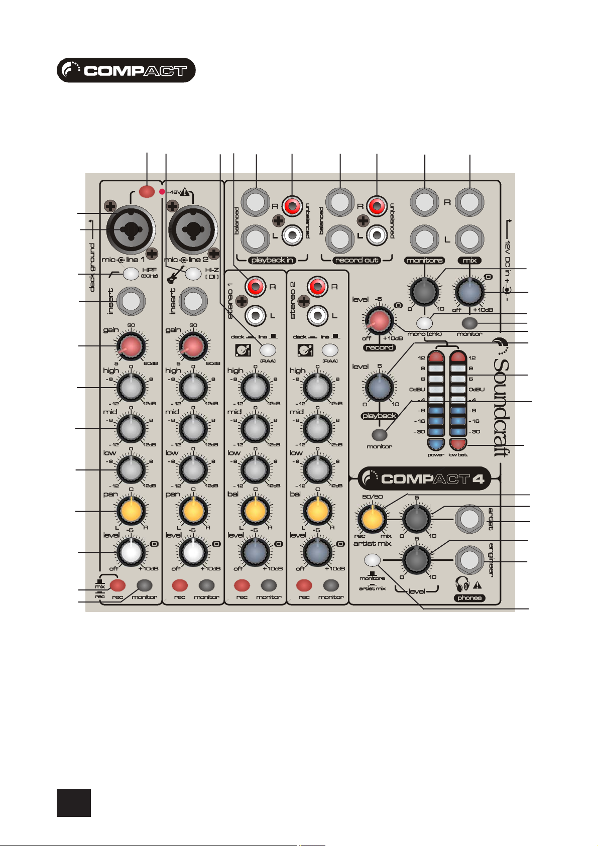
To get you working as fast as possible, this manual begins with a 10 second tutorial. Here you can find quick information on any feature of
the console, and a page reference where you can find a more detailed explanation.
Just pick out the feature you need more information on, find the associated number and read the brief explanation on the opposite page.
More detail can be found by delving deeper into the user guide.
Owners of Compact10 consoles will notice additonal jack inputs on Stereo Channels 1-4, these can be used for line level inputs from
synthesisers, samplers, drum machines etc.
m
NOTE: ALL SETTINGS ARE SHOWN IN THEIR DEFAULT POSITION - I.E. THE MOST COMMON SETTINGS TO BEGIN A SESSION
10
Page 11

USER GUIDEUSER GUIDE
USER GUIDE
USER GUIDEUSER GUIDE
THE 10 SECOND TUTOR - COMPTHE 10 SECOND TUTOR - COMP
THE 10 SECOND TUTOR - COMP
THE 10 SECOND TUTOR - COMPTHE 10 SECOND TUTOR - COMP
MIC INPUTMIC INPUT
1
MIC INPUT Connect Microphones here - read phantom power notes before use (pg 22)
MIC INPUTMIC INPUT
LINE INPUTLINE INPUT
2
LINE INPUT Connect Line level sources here, e.g. Synth, Drum Machine, etc (pg 22)
LINE INPUTLINE INPUT
HIGH PASS FILTER HIGH PASS FILTER
3
HIGH PASS FILTER This is used to remove very low frequencies i.e. mic “popping” (pg 22)
HIGH PASS FILTER HIGH PASS FILTER
INSERT POINTINSERT POINT
4
INSERT POINT Connect Signal processors here, e.g. Compressor, Gate etc (pg 23)
INSERT POINTINSERT POINT
GAIN CONTROL GAIN CONTROL
5
GAIN CONTROL Adjust this to increase or decrease the level of the incoming signal (pg 23)
GAIN CONTROL GAIN CONTROL
678
PAN CONTROL PAN CONTROL
9
PAN CONTROL Use this control to position the signal within the stereo field (pg 24)
PAN CONTROL PAN CONTROL
INPUT CHANNEL LEVEL INPUT CHANNEL LEVEL
0
INPUT CHANNEL LEVEL This is used to control the level fed to the Mix Bus (pg 24)
INPUT CHANNEL LEVEL INPUT CHANNEL LEVEL
REC(ORD) SWITCHREC(ORD) SWITCH
q
REC(ORD) SWITCH This sends the channel being recorded to the record outputs, or the Mix Bus (pg 24)
REC(ORD) SWITCHREC(ORD) SWITCH
MONITOR SWITCH MONITOR SWITCH
w
MONITOR SWITCH Press this to listen to the associated signal (pg 24)
MONITOR SWITCH MONITOR SWITCH
PHANTOM POWER PHANTOM POWER
e
PHANTOM POWER Switches on the phantom power (48V) for condenser microphones (pg 22)
PHANTOM POWER PHANTOM POWER
D.I. SWITCH D.I. SWITCH
r
D.I. SWITCH Direct Injection - Press this to get a better signal match when a bass guitar is used (pg 23)
D.I. SWITCH D.I. SWITCH
R.I.A.A. SWITCH R.I.A.A. SWITCH
t
R.I.A.A. SWITCH Vinyl Record Deck Compensation - Use only when decks are connected (pg 25)
R.I.A.A. SWITCH R.I.A.A. SWITCH
STEREO INPUTS STEREO INPUTS
y
STEREO INPUTS These two inputs take audio from keyboards, sound modules, samplers etc (pg 25)
STEREO INPUTS STEREO INPUTS
ui
op
MONITOR OUTPUTS MONITOR OUTPUTS
a
MONITOR OUTPUTS These are used to feed your speakers / amp, or monitoring system (pg 26)
MONITOR OUTPUTS MONITOR OUTPUTS
MIX OUTPUTS MIX OUTPUTS
s
MIX OUTPUTS Connect these to your recording device, or to your amplification system when using as a
MIX OUTPUTS MIX OUTPUTS
MONITOR LEVELMONITOR LEVEL
d
MONITOR LEVEL Used to adjust the level sent to your speakers / amp, or monitoring system (pg 26)
MONITOR LEVELMONITOR LEVEL
MIX LEVELMIX LEVEL
f
MIX LEVEL Used to adjust the level sent from the mix outputs (pg 26)
MIX LEVELMIX LEVEL
MONO (CHK) SWITCH MONO (CHK) SWITCH
g
MONO (CHK) SWITCH Use this to hear and check to your mix in mono (pg 26)
MONO (CHK) SWITCH MONO (CHK) SWITCH
MONITOR MIX MONITOR MIX
h
MONITOR MIX Use this to listen to the mix outputs (pg 26)
MONITOR MIX MONITOR MIX
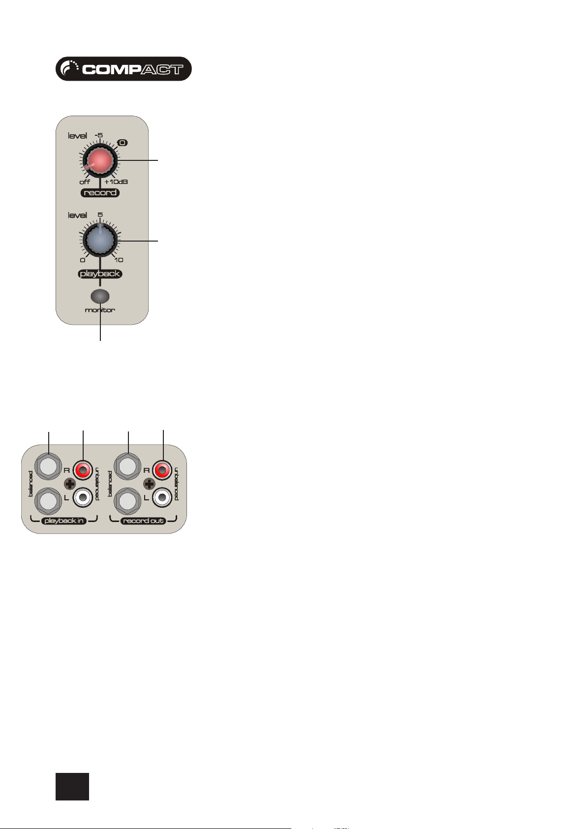
RECORD LEVELRECORD LEVEL
j
RECORD LEVEL Used to adjust the level sent to your soundcard or recording device (pg 28)
RECORD LEVELRECORD LEVEL
PLAYBACK LEVELPLAYBACK LEVEL
k
PLAYBACK LEVEL Used to adjust the level coming from your soundcard or recording device (pg 28)
PLAYBACK LEVELPLAYBACK LEVEL
MAIN METERS MAIN METERS
l
MAIN METERS These show the level of the signal being monitored (pg 26)
MAIN METERS MAIN METERS
MONITOR PLAYBACK MONITOR PLAYBACK
;
MONITOR PLAYBACK Use this to listen to the playback signal from your soundcard (pg 28)
MONITOR PLAYBACK MONITOR PLAYBACK
POWER / LOW BAT. POWER / LOW BAT.
z
POWER / LOW BAT. Indicators for DC power from the adapter, or the battery pack (pg 26)
POWER / LOW BAT. POWER / LOW BAT.
ARTIST MIX ARTIST MIX
x
ARTIST MIX This lets the artist choose the amount of playback signal required (pg 27)
ARTIST MIX ARTIST MIX
ARTIST LEVEL ARTIST LEVEL
c
ARTIST LEVEL This controls the level of the signal sent to the artist’s headphones (pg 27)
ARTIST LEVEL ARTIST LEVEL
ARTIST HEADPHONES ARTIST HEADPHONES
v
ARTIST HEADPHONES The artist should plug headphones in here for personal monitoring (pg 27)
ARTIST HEADPHONES ARTIST HEADPHONES
ENGINEER LEVEL ENGINEER LEVEL
b
ENGINEER LEVEL This controls the level of the signal sent to the engineer’s headphones (pg 27)
ENGINEER LEVEL ENGINEER LEVEL
ENGINEER HEADPHONESENGINEER HEADPHONES
n
ENGINEER HEADPHONES The engineer should plug headphones in here for standard monitoring (pg 27)
ENGINEER HEADPHONESENGINEER HEADPHONES
MONITORS/ARTIST MIXMONITORS/ARTIST MIX
m
MONITORS/ARTIST MIX The engineer, using headphones can listen to the monitor signal or the artist mix (pg 27)
MONITORS/ARTIST MIXMONITORS/ARTIST MIX
EQ STAGEEQ STAGE
EQ STAGE Adjust these controls to change the signal tone (the character of the signal) (pg 23)
EQ STAGEEQ STAGE
WARNING:WARNING:
WARNING: Do Not apply Phantom Power before connecting a microphone
WARNING:WARNING:
PLAYBACK INPUTS PLAYBACK INPUTS
PLAYBACK INPUTS Here you can connect the playback from your soundcard or recording device (pg 28)
PLAYBACK INPUTS PLAYBACK INPUTS
RECORD OUTPUTSRECORD OUTPUTS
RECORD OUTPUTS To connect the output from the mixer to your soundcard (or recording device) input (pg 28)
RECORD OUTPUTSRECORD OUTPUTS
standard mixer, not when using with a computer based system (pg 26)
ACT4 / COMPACT4 / COMP
ACT4 / COMP
ACT4 / COMPACT4 / COMP
ACT 10ACT 10
ACT 10
ACT 10ACT 10
11
Page 12

USER GUIDEUSER GUIDE
USER GUIDE
USER GUIDEUSER GUIDE
INTRODUCTIONINTRODUCTION
INTRODUCTION
INTRODUCTIONINTRODUCTION
Thank you for purchasing a Soundcraft mixer. We take great pride in our latest addition to our range
of mixing consoles - you have taken a step in the right direction and we will be with you all the way.
Owning a Soundcraft console brings you the expertise and support of one of the industry’s leading
manufacturers, and the results of over three decades of supporting some of the biggest names in
the business. Our knowledge has been attained through working in close contact with leading
professionals and institutes to bring you products designed to get the best possible results from
your mixing.
Built to the highest standards using quality components and surface mount technology, the Compact4
and Compact10 consoles are designed to be as easy to use as possible. We have spent years
researching the most efficient methods of control for two key reasons:
1) Engineers, musicians, writers and programmers all need to have very few interruptions
to the creative process; our products have been designed to be almost transparent,
allowing this process to breathe.
2) Whether performing or recording, time is a very expensive and rare commodity. Our
products have a user interface which is recognised by millions to be the industry standard
because of its efficiency.
The sonic qualities of our products are exemplary - some of the same circuits which are used on our
most expensive consoles are employed in the Compact4, bringing you the great Soundcraft quality
in a small format console without compromise.
You will also be glad to know you have a one year warranty with your product from the date of
purchase. The Compact4 and Compact10 consoles have been designed using the latest high-end
software based engineering packages. Every console from Soundcraft has been proven to stand up
to all the stress and rigours of modern day mixing environments.
The Compact4 and Compact10 consoles are manufactured using some of the most advanced
techniques in the world, from high density surface mount PCB technology, to computer aided test
equipment able to measure signals well outside the range of normal hearing.
As each console passes through to the quality checking stage (just before packing), there is also
a human listening station. Something we have learnt over the years is that the human touch counts
- and only by using people can you ensure the product meets the high demands of the user.
NOTE : The packaging which your Soundcraft Compact4 or Compact10 arrived in forms part of the
product, and must be retained for future use.
12
Page 13

USER GUIDEUSER GUIDE
USER GUIDE
USER GUIDEUSER GUIDE
WORKING SAFELWORKING SAFEL
WORKING SAFEL
WORKING SAFELWORKING SAFEL
Although your new console will not make any noise until you feed it signals, it has the capability to
produce sounds which when monitored through an amplifier or headphones can damage hearing
over time.
The table below is taken from the Occupational Safety & Health Administration directive on
Occupational noise exposure (1926.52):
PERMISSABLE NOISE EXPOSUREPERMISSABLE NOISE EXPOSURE
PERMISSABLE NOISE EXPOSURE
PERMISSABLE NOISE EXPOSUREPERMISSABLE NOISE EXPOSURE
DURATION PER DAY, HOURS SOUND LEVEL dBA SLOW RESPONSE
890
692
495
397
2 100
1.5 102
1 105
0.5 110
<0.25 115
Conforming to this directive will minimise the risk of hearing damage caused by long listening
periods. A simple rule to follow is the longer you listen the lower the average volume should be.
Y WITH SOUNDY WITH SOUND
Y WITH SOUND
Y WITH SOUNDY WITH SOUND
Please take care when working with your audio - if you are manipulating controls which you don’t
understand (which we all do when we are learning), make sure your monitors are turned down.
Remember that your ears are the most important tool of your trade, look after them, and they will
look after you.
Most importantly - don’t be afraid to experiment to find out how each parameter affects the sound
- this will extend your creativity and help you to get the best results.
13
Page 14

USER GUIDEUSER GUIDE
USER GUIDE
USER GUIDEUSER GUIDE
THE MIXER EXPLAINEDTHE MIXER EXPLAINED
THE MIXER EXPLAINED
THE MIXER EXPLAINEDTHE MIXER EXPLAINED
What is an audio mixer ?What is an audio mixer ?
What is an audio mixer ?
What is an audio mixer ?What is an audio mixer ?
The term “mixing” is the combining of audio channels, in most cases to form a stereo output signal
made up of left and right channels. Mixers normally have level controls (or faders) on each input
to set the required amount of audio before the mixing stage
What other functions can a Compact mixer perform ?What other functions can a Compact mixer perform ?
What other functions can a Compact mixer perform ?
What other functions can a Compact mixer perform ?What other functions can a Compact mixer perform ?
The Compact4 and Compact10 consoles can also be used to process audio. You can:
a) Apply Equalisation ( change the tone of the audio ). This is done using the EQ
controls for the low, mid and high bands.
b) Place an audio processor over a particular signal, this is achieved using the insert
point to peform additional processing such as compression, or adding fx such as reverb.
c) Control the audio position within the stereo field (the sound stage created by your
speakers/monitors).
d) Increase or decrease the incoming signal level in order to achieve the best signal to
noise ratio (audio quality). This parameter is known as “gain”.
The Compact4 and Compact10 consoles can also be used to route audio, you can:
a) Send audio to record outputs, normally fed to your recording system.
The source can be unbalanced for use with consumer soundcards, or balanced for
professional soundcards.
b) Send audio to the mix output, used to feed a PA when performing.
The term “monitoring” can be more simply described as listening to audio channels. Mixers
normally have monitor switches in various parts of the mixing process to check channels, before
and after mixing.
The Compact4 and Compact10 consoles can also be used to monitor (using ears and eyes) audio.
You can:
a) Send audio to the LED meters and the monitor outputs simultaneously. You always
see what you hear from your monitor outputs which will feed the speakers in your main
listening position.
b) Send audio to the artist headphone output, used to allow the artist to independently
control their own personal mix without affecting any other outputs
b) Send audio to the artist headphone output, used to allow the artist to independently
control their own personal mix without affecting any other outputs
14
Page 15

USER GUIDEUSER GUIDE
USER GUIDE
USER GUIDEUSER GUIDE
What kind of things can I plug into it ?What kind of things can I plug into it ?
What kind of things can I plug into it ?
What kind of things can I plug into it ?What kind of things can I plug into it ?
We can’t possibly list all of them here, but below are a few of the most common sources:
a) Microphones, both dynamic and condensor types can be used. Channel One also
has a high-pass filter which removes the sub bass frequencies when singing “b” and “p”
sounds.
b) Guitars, there is even a DI circuit to enhance bass guitars, which is located on a mono
channel
c) Synths/Keyboards, line level stereo outputs can be fed to the stereo input channels.
d) Decks, or turntables if you’re that way inclined, can be fed to stereo inputs with RIAA
Equalisation. The RIAA Equalisation returns the tone of the deck input to that of the
original signal (as RIAA-EQ is applied when cutting vinyl).
e) Computer, both Mac and PC systems have a host audio card, often found on the
motherboard. The unbalanced connection from the host (or consumer soundcard) can
be connected to the phono playback inputs.
f) Professional Soundcards, or Digital Audio Workstations can be connected to the
3-pole ‘A’ gauge balanced jack playback inputs.
g) CDR/DAT/MD/MP3 - the outputs of these consumer, or professional devices can be
connected to the unbalanced phono inputs, or the 3-pole ‘A’ gauge balanced jack stereo
inputs (Compact10 only).
h) Another mixer, often called a sub-mixer will be used to mix a drum kit, or an orchestral
outfit. The outputs of this mixer can be connected to the unbalanced phono inputs, or the
3-pole ‘A’ gauge balanced jack stereo inputs (Compact10 only).
Wow that’s a lot of stuff for such a small mixer ?Wow that’s a lot of stuff for such a small mixer ?
Wow that’s a lot of stuff for such a small mixer ?
Wow that’s a lot of stuff for such a small mixer ?Wow that’s a lot of stuff for such a small mixer ?
Yes it is, you should be happy, you made a good choice.
Why don’t other manufacturers design consoles like this ?Why don’t other manufacturers design consoles like this ?
Why don’t other manufacturers design consoles like this ?
Why don’t other manufacturers design consoles like this ?Why don’t other manufacturers design consoles like this ?
a) Because they are out of touch ?
b) Because they are not very innovative ?
c) Because they don’t have the experience ?
d) Because they don’t listen to their users ?
Who knows :-)
15
Page 16
USER GUIDEUSER GUIDE
USER GUIDE
USER GUIDEUSER GUIDE
MIXING AUDIO PMIXING AUDIO P
MIXING AUDIO P
MIXING AUDIO PMIXING AUDIO P
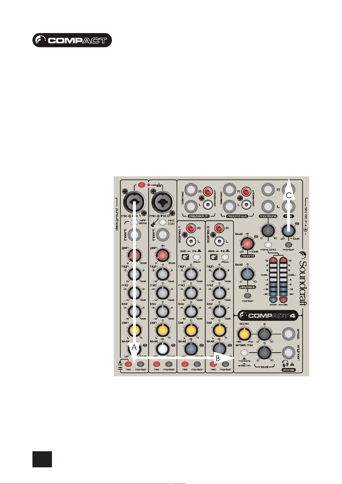
So how does audio get mixed ?So how does audio get mixed ?
So how does audio get mixed ?
So how does audio get mixed ?So how does audio get mixed ?
The audio path shown below covers :
A - The input channel path from the microphone input to the mix bus (where all the
signals are mixed together). Remember this is a stereo signal.
B - The mix bus from input channel level to mix output level
C - The mix output level control to the mix outputs
AA
A
AA
THTH
TH
THTH
16
Page 17
USER GUIDEUSER GUIDE
USER GUIDE
USER GUIDEUSER GUIDE
MONITORING AUDIO PMONITORING AUDIO P
MONITORING AUDIO P
MONITORING AUDIO PMONITORING AUDIO P
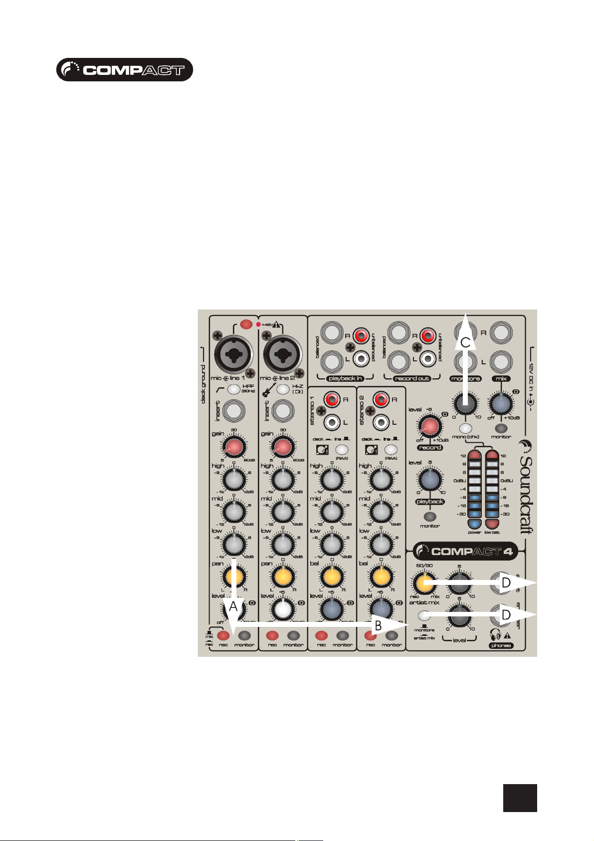
So how do I listen to audio ?So how do I listen to audio ?
So how do I listen to audio ?
So how do I listen to audio ?So how do I listen to audio ?
The audio path shown below covers :
A - The channel monitor button which sends audio (before any pan and level control) to
the monitor bus - this is another bus used to add signals for listening. This is normally
used to set-up the channel
B - The monitor bus from to monitor output level and headphone output levels
C - The monitor output level control to the monitor outputs
D - The headphone output levels control to the headphone outputs
AA
A
AA
THTH
TH
THTH
17
Page 18

USER GUIDEUSER GUIDE
USER GUIDE
USER GUIDEUSER GUIDE
WIRING UPWIRING UP
WIRING UP
WIRING UPWIRING UP
Mic InputMic Input
Mic Input
Mic InputMic Input
The outer ring of the combination input accepts XLR-type connectors and is designed to suit a wide
range of BALANCED or UNBALANCED low-level signals, whether from delicate vocals requiring the
best low-noise performance, or drum kits needing maximum headroom. Professional dynamic,
condenser or ribbon mics are best because these will be LOW IMPEDANCE. While you can use lowcost HIGH IMPEDANCE mics, you do not get the same degree of immunity to interference on the
microphone cable and as a result the level of background noise may be higher. If you turn the
PHANTOM POWER on, the socket provides a suitable powering voltage for professional condenser
mics.
DO NOT use UNBALANCED sources with the phantom power
switched on. The voltage on pins 2 & 3 of the XLR connector
may cause serious damage. BALANCED dynamic mics may
normally be used with phantom power switched on (contact
your microphone manufacturer for guidance)
WARNING !
Start with the input GAIN knob turned fully anticlockwise
when plugging high level sources into the LINE input to avoid
overloading the input channel or giving you a very loud
surprise!
The input level is set using the input GAIN knob.
The LINE input offers the same gain range as the MIC input, but at a higher input impedance, and
is 20dB less sensitive. This is suitable for most line level sources.
Line InputLine Input
Line Input
Line InputLine Input
The centre of the combination input accepts 3-pole ‘A’ gauge jacks, or 2-pole mono jacks which
will automatically ground the ‘cold’ input. Use this input for sources other than mics, such as
keyboards, drum machines, synths, tape machines or guitars. The input is BALANCED for low noise
and immunity from interference, but you can use UNBALANCED sources by wiring up the jacks as
shown, although you should then keep cable lengths as short as possible to minimise interference
pick-up on the cable. Note that the ring must be grounded if the source is unbalanced. Set the
input level using the GAIN knob, starting with the knob turned fully anticlockwise. Unplug any MIC
connection when using the LINE input.
InserInser
t Pointt Point
Inser
t Point
InserInser
t Pointt Point
18
The unbalanced, pre-EQ insert point is a break in the channel signal path, allowing limiters,
compressors, special EQ or other signal processing units to be placed directly in the signal path.
The Insert is a 3-pole ‘A’ gauge jack socket which is normally bypassed. When a jack is inserted,
the signal path is broken, just before the EQ section.
The signal from the channel (often called the SEND) appears on the TIP of the plug and comes
back (often called the RETURN) on the RING, with the sleeve as a common ground.
The signal may be also be used to feed as an alternative pre-fade, pre-EQ direct output if required,
using a lead with tip and ring shorted together so that the signal path is not interrupted.
Page 19

USER GUIDEUSER GUIDE
USER GUIDE
USER GUIDEUSER GUIDE
Using an InserUsing an Inser
Using an Inser
Using an InserUsing an Inser
Shown below is the wiring diagram for an insert cable. Your Soundcraft dealer or local disributor
should also stock this type of cable.
Stereo Inputs Compact4Stereo Inputs Compact4
Stereo Inputs Compact4
Stereo Inputs Compact4Stereo Inputs Compact4
These accept 2-pole phono plugs which will automatically ground the ‘cold’ input. Use these
inputs for sources such as keyboards, drum machines, synths, tape machines or as returns from
processing units.
The input is UNBALANCED and you should then keep cable lengths as short as possible to
minimise interference pick-up on the cable.
Stereo Inputs Compact10Stereo Inputs Compact10
Stereo Inputs Compact10
Stereo Inputs Compact10Stereo Inputs Compact10
t Cablet Cable
t Cable
t Cablet Cable
These accept 3-pole ‘A’ gauge jacks, or 2-pole phono plugs which will automatically ground the
‘cold’ input. Use these inputs for sources such as keyboards, drum machines, synths, tape
machines or as returns from processing units.
The inputs are BALANCED for low noise and immunity from interference, but you can use
UNBALANCED sources by wiring up the jacks as shown, although you should then keep cable
lengths as short as possible to minimise interference pick-up on the cable. Note that the ring must
be grounded if the source is unbalanced.
Mono sources can be fed to both paths by plugging into the Left jack only, and pressing the MONO
switch.
NOTE: Please refer to pages 40/41 for additional wiring details.
Mix Outputs
The Mix outputs are on 3-pole ‘A’ gauge jack sockets, wired as shown on the left, and are balanced,
allowing long cable runs to balanced amplifiers and other equipment.
Monitor Outputs
The Monitor outputs are on 3-pole ‘A’ gauge jack sockets, wired as shown on the left, and are
balanced, allowing long cable runs to balanced amplifiers and other equipment.
19
Page 20

USER GUIDEUSER GUIDE
USER GUIDE
USER GUIDEUSER GUIDE
ArAr
tist and Engineer Headphonestist and Engineer Headphones
Ar
tist and Engineer Headphones
ArAr
tist and Engineer Headphonestist and Engineer Headphones
The Headphones outputs are on a 3-pole ‘A’ gauge jack, wired as a stereo output as shown, The
output level is designed ideally for headphones of 200Ω or greater. 8Ω headphones are not
recommended, although can be used.
Polarity (Phase)Polarity (Phase)
Polarity (Phase)
Polarity (Phase)Polarity (Phase)
You will probably be familiar with the concept of polarity in electrical signals and this is of particular
importance to balanced audio signals. Just as a balanced signal is highly effective at cancelling
out unwanted interference, so two microphones picking up the same signal can cancel out, or
cause serious degradation of the signal if one of the cables has the +ve and -ve wires reversed.
This phase reversal can be a real problem when microphones are close together and you should
therefore always take care to connect pins correctly when wiring audio cables.
Grounding and ShieldingGrounding and Shielding
Grounding and Shielding
Grounding and ShieldingGrounding and Shielding
For optimum performance use balanced connections where possible and ensure that all signals
are referenced to a solid, noise-free earthing point and that all signal cables have their screens
connected to ground. In some unusual circumstances, to avoid earth or ground ‘loops’ ensure that
all cable screens and other signal earths are connected to ground only at their source and not at
both ends.
If the use of unbalanced connections is unavoidable, you can minimise noise by following these
wiring guidelines:
• On INPUTS, unbalance at the source and use a twin screened cable as though it were
balanced.
• On OUTPUTS, connect the signal to the +ve output pin, and the ground of the output device
to -ve. If a twin screened cable is used, connect the screen only at the mixer end.
• Avoid running audio cables or placing audio equipment close to thyristor dimmer units or
power cables.
• Noise immunity is improved significantly by the use of low impedance sources, such as
good quality professional microphones or the outputs from most modern audio equipment.
Avoid cheaper high impedance microphones, which may suffer from interference over long
cable runs, even with well-made cables.
Grounding and shielding is still seen as a black art, and the suggestions above are only guidelines.
If your system still hums, an earth/ground loop is the most likely cause. Two examples of how an
earth loop can occur are shown below.
20
WARNING! Under NO circumstances must the AC power
mains earth be disconnected from the mains lead.
Page 21

USER GUIDEUSER GUIDE
USER GUIDE
USER GUIDEUSER GUIDE
PROBLEM SOLPROBLEM SOL
PROBLEM SOL
PROBLEM SOLPROBLEM SOL
Basic problem solving is within the capability of any user if a few basic rules are followed.
VINGVING
VING
VINGVING
• Get to know the Block Diagram of your console (see page 42).
• Get to know what all parameters and/or connections in the system are supposed to do.
• Learn where to look for common trouble spots.
The Block Diagram is a representative sketch of all the components of the mixer, showing how they
connect together and how the signal flows through the system. Once you have become familiar
with the various component blocks you will find the Block Diagram is quite easy to follow and you
will have gained a valuable understanding of the internal structure of the mixer.
Each component has a specific function and only by getting to know what each part is supposed to
do will you be able to tell if there is a genuine fault! Many “faults” are the result of incorrect
connection or control settings which may have been overlooked.
Basic Troubleshooting is a process of applying logical thought to the signal path through the mixer
and tracking down the problem by elimination.
• Swap input connections to check that the source is really present. Check both Mic and Line
inputs.
• Eliminate sections of the channel by using the insert point to re-route the signal to other
inputs that are known to be working.
• Route channels to different outputs or to auxiliary sends to identify problems on the Master
section.
• Compare a suspect channel with an adjacent channel which has been set up identically.
Use the MONITOR switches to hear the signal in each section.
• Problems with the Insert jack sockets contacts may be checked by using an insert bypass
jack with tip and ring shorted together as shown to the left. If the signal appears when the
jack is inserted it shows that there is a problem with the contacts on the jack socket,
caused by wear or damage, or often just dirt or dust. Keep a few in your gig tool box.
If in doubt please contact Soundcraft customer support.
PRODUCTS UNDER WARRANTY
USA customers should contact the National Service Manager at Soundcraft USA, telephone: (615)
360-0458, e-mail: soundcraft-usa@harman.com.
UK customers should contact their local Dealer.
Outside the UK and USA, customers are requested to contact their territorial distributor who is able
to offer support in the local time zone and language. Please see the Distributor listings on our
website (http://www.soundcraft.com) to locate your Local Distributor.
OUT-OF-WARRANTY PRODUCTS
For out-of-warranty mixers purchased in the United Kingdom, please contact the Customer Services
Department (e-mail: csd@soundcraft.com) at the factory in Potters Bar, Hertfordshire: Telephone
+44 (0)1707 665000.
For all other out-of-warranty mixers, please contact the appropriate territorial distributor.
When mailing or faxing please remember to give as much information as possible. This should
include your name, address and a daytime telephone number.
Should you experience any difficulty please contact Customer Services Department (e-mail:
csd@soundcraft.com)
21
Page 22

1
2
3
4
USER GUIDEUSER GUIDE
USER GUIDE
USER GUIDEUSER GUIDE
MONO INPUT CHANNELSMONO INPUT CHANNELS
MONO INPUT CHANNELS
MONO INPUT CHANNELSMONO INPUT CHANNELS
1 PHANTOM POWER
When using condensor microphones +48v phantom power is required to be present at the contacts
of the microphone (XLR) socket for the microphone to operate correctly. Phantom power can only
be applied to both microphone inputs simultaneously so ensure that phantom power is off when
not required.
ONLY connect condenser microphones with the +48V
powering OFF, and ONLY turn the +48V powering on or off
with ALL OUTPUT LEVEL CONTROLS DOWN, to prevent
damage to the mixer or external devices.
6
7
8
TAKE CARE when using unbalanced sources, which may be damaged by the phantom power
voltage on pins 2 & 3 of the XLR connector.
Unplug any mics if you want to use the LINE Input. The input level is set using the GAIN knob as
described in point (7).
2 MIC INPUT
The MIC input accepts XLR-type connectors and is designed to suit a wide range of BALANCED or
UNBALANCED signals. Professional dynamic, condenser or ribbon mics are best because these
will be LOW IMPEDANCE. You can use low-cost HIGH IMPEDANCE mics, but the level of background
noise will be higher. If you turn the PHANTOM POWER on (top right-hand side of the mixer) the
socket provides a suitable powering voltage for professional condenser mics.
3 LINE INPUT
Accepts 3-pole ‘A’ gauge (TRS) jacks. Use this input for sources other than mics, such as
keyboards, drum machines, synths, tape machines or DI’d guitars. The input is BALANCED for low
noise and top quality from professional equipment, but you can use UNBALANCED sources by
wiring up the jacks as shown below, although you should then keep cable lengths as short as
possible. Unplug anything in the MIC input if you want to use this socket. Set the input level using
the GAIN knob.
22
4 HIGH PASS FILTER SWITCH
Pressing this switch activates a steep 12dB per octave filter which reduces the level of subharmonic bass frequencies. This is very useful for removing mic-pops caused by the large volumes
of air pushed out rapidly when singing [P] or [B] sounds. It can also be used to get rid of “rumble”
caused by a microphone on stage, or to simply clean up a mix.
Page 23

USER GUIDEUSER GUIDE
USER GUIDE
USER GUIDEUSER GUIDE
5
DIRECT INJECTION SWITCH
This switch activates the high impedance mode for the 3-pole ‘A’ gauge jack input. The high
impedance is used to match the signal from a high-impedance source such as bass guitars. When
activating you will notice the guitar sound will become much bolder. Using impedance matching
this way for guitar inputs is known as “Direct Injection” When using as bass guitar without the DI
switch activated, you may notice a reduction on the high frequencies produced.
NOTE 1- The high pass filter switch is featured on channel 1 of the Compact4, and channels 1&2
on the Compact10.The direct injection switch is featured on channel 2 of the Compact4, and
channels 3&4 on the Compact10
5
6
7
8
6 INSERT POINT
The unbalanced, pre-EQ insert point is a break in the channel signal path, allowing limiters,
compressors, special EQ or other signal processing units to be added in the signal path. The Insert
is a 3-pole ‘A’ gauge jack socket which is normally bypassed. When a jack is inserted, the signal
path is broken, just before the EQ section. The Send may be tapped off as an alternative pre-fade,
pre-EQ direct output if required, using a lead with tip and ring shorted together so that the signal
path is not interrupted (see pages 18/19).
7 GAIN CONTROL
This knob sets how much of the source signal is sent to the rest of the mixer. Too high, and the
signal will distort as it overloads the channel. Too low, and the level of any background hiss will
be more noticeable and you may not be able to get enough signal level to the output of the mixer.
Note that some sound equipment, particularly that intended for domestic use, operates at a lower
level (-10dBV) than professional equipment and will therefore need a higher gain setting to give
the same output level.
8 EQUALISER
The Equaliser (EQ) allows fine manipulation of the sound, particularly to improve the sound in live
PA applications where the original signal is often far from ideal and where slight boosting or cutting
of particular voice frequencies can really make a difference to clarity. There are three sections
giving the sort of control usually only found on much larger mixers. The EQ knobs can have a
dramatic effect, so use them sparingly and listen carefully as you change any settings so that you
get to know how they affect the sound.
HF EQHF EQ
HF EQ
HF EQHF EQ
Turn to the right to boost high (treble) frequencies above 12kHz by up to 12dB, adding crispness
to cymbals, vocals and electronic instruments. Turn to the left to cut by up to 12dB, reducing hiss
or excessive sibilance which can occur with certain types of microphone. Set the knob in the
centre-detented position when not required.
MID EQMID EQ
MID EQ
MID EQMID EQ
This control knob provides 12dB of boost and cut, just like the HF EQ knob, but at the frequency of
600Hz. The frequency has been chosen to represent a balance covering the range of most vocals.
Listen carefully as you use this control to find how particular characteristics of a vocal signal can be
enhanced or reduced. Set the knob to the centre-detented position when not required.
LF EQLF EQ
LF EQ
LF EQLF EQ
Turn to the right to boost low (bass) frequencies below 60Hz by up to 12dB, adding warmth to
vocals or extra punch to synths, guitars and drums. Turn to the left to cut low frequencies by up to
12dB for reducing hum, stage rumble or to improve a mushy sound. Set the knob to the centredetented position when not required.
23
Page 24

USER GUIDEUSER GUIDE
USER GUIDE
USER GUIDEUSER GUIDE
MONO INPUT CHANNELS - CONTINUEDMONO INPUT CHANNELS - CONTINUED
MONO INPUT CHANNELS - CONTINUED
MONO INPUT CHANNELS - CONTINUEDMONO INPUT CHANNELS - CONTINUED
1 PAN
This control sets the amount of the channel signal feeding the Left and Right MIX buses, allowing
you to move the source smoothly across the stereo image. When the control is turned fully left or
right you are able to route the signal with no gain to either left or right outputs individually.
2 CHANNEL LEVEL CONTROL
The rotary level control, with a custom-designed law to give even smoother control of the overall
signal level in the channel strip, allows precise balancing of the various source signals being
mixed to the Master Section. You get most control when the input GAIN is set up correctly, giving
the full rotation of the level control. See the “Initial Setup” section on page 30 for help in setting
a suitable signal level.
3 MONITOR SWITCH
When the latching MONITOR switch is pressed, the pre-fade signal is fed to the mix, for setting up
and making adjustments in isolation from other channels. The monitor signal is a true stereo
signal, it does not get summed to a mono bus as in some other, more generic mixers. This means
when you monitor a channel the positional information is never lost, you always here a signal how
it would appear in the stereo field (the sound stage in front of you reproduced using speakers).
3
4
4
3
1
2
4 RECORD SWITCH
When pressed this sends the channel audio out to the record outputs. These record outputs must
be connected to your soundcard inputs. There are three advantages of having this feature:
1. You will only ever record the channel/s which have the Record switch pressed. With more
complex mixers, a common error is recording additional unrequired instruments, or open channels
adding noise to your recording.
2. The artist will not have to deal with the latency of the recording hardware/software. On other,
more generic mixers it is common to monitor the recording signal from the computer, this means
there is a delay which can be extremely fustrating for all performers, especially drummers, where
timing is critical. Using the “zero-latency” monitoring means that the signal is sent to the headphones
directly
3. It makes the recording procedure simple and fast to learn, and intuitive to use.
24
Page 25

9
USER GUIDEUSER GUIDE
USER GUIDE
USER GUIDEUSER GUIDE
STEREO INPUT CHANNELSSTEREO INPUT CHANNELS
STEREO INPUT CHANNELS
STEREO INPUT CHANNELSSTEREO INPUT CHANNELS
5 INPUTS STEREO 1/2
These inputs accept 2-pole Phono plugs. Use these inputs for sources such as keyboards, drum
machines, synths, CD/DVD Players, tape machines or processing units. The inputs are UNBALANCED
for use with consumer and semi-professional equipment, although you should then keep cable
lengths as short as possible.
6 RIAA EQUALISATION
When Vinyl is recorded an EQ curve is applied to maximise the dynamic range at the cutting stage.
Engaging this switch reverses the EQ curve, returning the signal to its former glory. Use this for
turntable inputs which do not have built-in RIAA equalisation.
3
4
5
0
7
8
2
NOTE: When using turntables, ensure you connect the turntable earth to the earth stud on the left
hand side of the console (recessed in the side cheek).
7 EQUALISER
HF EQHF EQ
HF EQ
HF EQHF EQ
Turn to the right to boost high (treble) frequencies above 12kHz by up to 12dB, adding crispness
to cymbals, vocals and electronic instruments. Turn to the left to cut by up to 12dB, reducing hiss
or excessive sibilance which can occur with certain types of microphone. Set the knob in the
centre-detented position when not required.
MID EQMID EQ
MID EQ
MID EQMID EQ
This control knob provides 12dB of boost and cut, just like the HF EQ knob, but at the frequency of
600Hz. Listen carefully as you use this control to find how particular characteristics of a vocal
signal can be enhanced or reduced. Set the knob to the centre-detented position when not
required.
LF EQLF EQ
LF EQ
LF EQLF EQ
Turn to the right to boost low (bass) frequencies below 60Hz by up to 12dB, adding warmth to
vocals or extra punch to synths, guitars and drums. Turn to the left to cut low frequencies by up to
12dB for reducing hum, stage rumble or to improve a mushy sound. Set the knob to the centredetented position when not required.
8 BALANCE
This control sets the amount of the channel signal feeding the Left and Right MIX buses, allowing
you to balance the source in the stereo image. When the control is turned fully right or left you feed
only that side of the signal to the mix. The zero gain is provided by the control in the centredetented position.
4
3
6
Compact10 Stereo Channels 1-4Compact10 Stereo Channels 1-4
Compact10 Stereo Channels 1-4
Compact10 Stereo Channels 1-4Compact10 Stereo Channels 1-4
9 1/4” 3-pole jack inputs are found on the Compact10
Mixing Console
0 NOTE - The stereo inputs can also be used as a MONO channel. You can do this by
pressing the MONO switch, this is found on stereo channels 1-4.
25
Page 26

2
1
3
4
6
USER GUIDEUSER GUIDE
USER GUIDE
USER GUIDEUSER GUIDE
MASTER SECTIONMASTER SECTION
MASTER SECTION
MASTER SECTIONMASTER SECTION
1 MONITOR OUTPUTS
The Monitor LEFT and RIGHT outputs are sent from the 3-pole ‘A’ gauge jacks sockets as balanced
signals.
2 MONITOR LEVEL
This control sets the level to the MONITOR LEFT & RIGHT outputs.
3 MONO (CHK)
This switch when activated performs a mono sum of the monitor signal so that you can check how
5
your stereo signal would be heard in mono.
4 MIX OUTPUTS
The Monitor LEFT and RIGHT outputs are sent from the 3-pole ‘A’ gauge jacks sockets as balanced
signals.
5 MIX LEVEL
The MIX level control is used to set the final level of the MIX outputs. These should normally be set
close to the ‘0’ mark if the input GAIN settings have been correctly set, to give maximum resolution
for the overall signal to noise ratio.
89
6 MONITOR MIX
Pressing this switch will allow you to hear all the signals sent to the MIX bus.
7 BARGRAPH METERS
The three-colour peak reading BARGRAPH METERS show the level of the MONITOR RIGHT and
MONITOR LEFT outputs, giving you a constant warning of excessive peaks in the signal which might
cause overloading.
Aim to keep the signal within the white segments at peak levels for best performance. If the top
segment lights RED then you have reached a point where the signal will clip and begin distorting,
reduce the input level accordingly.
Similarly, if the output level is too low and hardly registering at all on the meters, the level of
background noise may become significant. Take care to set up the input levels for best performance.
7
When any MONITOR switch is pressed, the meters switch to show the selected MONITOR signal on
both meters, in true stereo.
8 POWER INDICATOR
This LED lights to show when power is connected to the console.
9 LOW BATTERY INDICATOR
This LED will flash red to show when the batteries have reached a dangerously low level and
should be replaced by fresh batteries, or mains power as soon as possible.
26
Page 27

USER GUIDEUSER GUIDE
USER GUIDE
USER GUIDEUSER GUIDE
MASTER SECTIONMASTER SECTION
MASTER SECTION
MASTER SECTIONMASTER SECTION
3
6
2
5
1 ARTIST HEADPHPONES OUTPUT
The Artist Headphones Outputs are on 3-pole ‘A’ gauge jacks and are unbalanced connections
wired as a stereo output. There is a substantial amount of power at these sockets depending on the
type of headphones you use. Remember the higher the impedance of the headphones normally
1
means the louder they will be. The circuit has been designed for use with consumer and professional
headphones. Ideally headphones should be 200Ω or greater. 8Ω headphones are not
recommended.
4
2 ARTIST HEADPHONES LEVEL
This control sets the output level to the Artist Headphone outputs. If headphones are plugged into
the PHONES jack, then the knob sets a comfortable headphone listening level without affecting the
Monitor output levels.
3 ARTIST MIX CONTROL
This control allows the artist to hear a personal blend of the playback signal and the recorded
signal. Some vocalists may want to hear a fairly low level version of their voice and hear much
more of the playback so that they can “key” clearly. It can be used to allow the artist a personal mix
which effects neither the monitor outputs nor the engineer headphones.
4 ENGINEER HEADPHONES OUTPUT
The Engineer Headphones Outputs are on 3-pole ‘A’ gauge jacks and are unbalanced connections
wired as a stereo output. There is a substantial amount of power at these sockets depending on the
type of headphones you use. Remember the higher the impedance of the headphones normally
means the louder they will be. The circuit has been designed for use with consumer and professional
headphones. Ideally headphones should be 200Ω or greater. 8Ω headphones are not
recommended.
5 ENGINEER HEADPHONES LEVEL
This control sets the output level to the Artist Headphone outputs. If headphones are plugged into
the PHONES jack, then the knob sets a comfortable headphone listening level without affecting the
Monitor output levels.
6 MONITOR ARTIST PHONES
Press this switch to route the Artist Mix signal to the engineer head phones, over-riding the default
Monitor/Phones signal. This allows the engineer to hear what the artist is hearing (useful for
resolving communication errors between the artist and engineer :-) ), or for the engineer to become
the artist (a common dual personality problem).
27
Page 28
1
USER GUIDEUSER GUIDE
USER GUIDE
USER GUIDEUSER GUIDE
MASTER SECTIONMASTER SECTION
MASTER SECTION
MASTER SECTIONMASTER SECTION
1 RECORD OUTPUT LEVEL
This control sets the output level to the RECORD outputs. The input monitor of your soundcard/
sequencer should be checked for a good level of signal. If you have followed the set-up procedure,
this knob should be around the 0dB position.
2 PLAYBACK INPUT LEVEL
This control sets the input level of the playback signal. Again if your soundcard/sequencer is setup
correctly, and using maximum resolution you should find this control at the position 7 (0-10).
4
5
3
6
2
7
3 MONITOR PLAYBACK
When the latching MONITOR switch is pressed, the post-fade signal is fed to the monitor bus, for
setting up and making adjustments in isolation from other channels. The monitor signal is a true
stereo signal, it does not get summed to a mono bus as in some other, more generic mixers. This
means when you monitor a channel the positional information is never lost, you always hear a
signal how it would appear in the stereo field (the sound stage in front of you reproduced using
speakers).
4 PLAYBACK INPUTS - BALANCED
The Playback LEFT and RIGHT Inputs accept 3-pole ‘A’ gauge (TRS) jacks. Use these inputs for the
outputs from your soundard/sequencer The inputs are BALANCED for low noise and top quality
from professional equipment, but you can use UNBALANCED sources (see wiring diagram on page
18)
5 PLAYBACK INPUTS - UNBALANCED
The Playback LEFT and RIGHT Inputs also accept 2-pole Phono plugs. Use these inputs for the
outputs from your soundcard/sequencer The inputs are UNBALANCED for use with consumer and
semi-proffesional equipment, although you should then keep cable lengths as short as possible.
6 RECORD OUTPUTS - BALANCED
The Record LEFT and RIGHT outputs are sent from the 3-pole ‘A’ gauge jacks sockets as balanced
signals.
28
7 RECORD OUTPUTS - UNBALANCED
The Record LEFT and RIGHT Outputs are also available on 2-pole Phono plugs. Use these outputs
to send the recording signal to your soundcard or sequencer The outputs are UNBALANCED for use
with consumer and semi-professional equipment, again you should then keep cable lengths as
short as possible.
Page 29
USER GUIDEUSER GUIDE
USER GUIDE
USER GUIDEUSER GUIDE
USING YOUR COMPUSING YOUR COMP
USING YOUR COMP
USING YOUR COMPUSING YOUR COMP
The final sound from your monitoring system can only ever be as good as the weakest link in the
chain, and especially important is the quality of the source signal because this is the starting point
of the chain. Just as you need to become familiar with the control functions of your mixer, so you
must recognise the importance of correct choice of inputs, microphone placement and input
channel settings. However, no amount of careful setting up can take account of the spontaneity
and unpredictability of live performance. The mixer must be set up to provide “spare” control range
to compensate for changing microphone position and the absorption effect of a large audience
(different acoustic characteristics from soundcheck to show).
ACT 4/10 MIXERACT 4/10 MIXER
ACT 4/10 MIXER
ACT 4/10 MIXERACT 4/10 MIXER
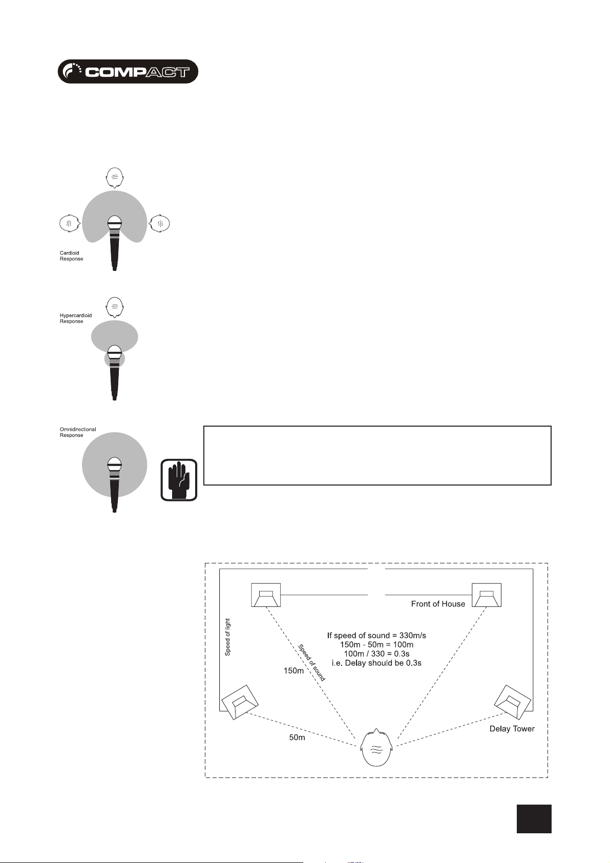
MICROPHONE PLACEMENT
Careful microphone placement and the choice of a suitable type of microphone for the job is one
of the essentials of successful sound reinforcement. The diagrams on the left show the different
pick-up patterns for the most common types of microphone. Cardioid microphones are most
sensitive to sound coming from in front, and hypercardioid microphones offer even greater directivity,
with a small amount of pickup behind the microphone. These types are ideal for recording
vocalists or instruments, where rejection of unwanted sounds and elimination of feedback is
important. The aim should be to place the microphone as close as physically possible to the
source, to cut out unwanted surrounding sounds, allow a lower gain setting on the mixer and avoid
feedback. Also a well chosen and well placed microphone should not need any appreciable
equalisation.
There are no exact rules - let your ears be the judge. In the end, the position that gives the desired
effect is the correct position!
The front panel drawing on page 10 shows typical initial
control positions which is a useful guide to setting up
the mixer for the first time.
MONITORING TIPSMONITORING TIPS
MONITORING TIPS
MONITORING TIPSMONITORING TIPS
The diagram below shows how to set-up speakers in a live environment, the front of house
speakers are shown, although you should consult your studio monitor manual for precise placement.
29
Page 30

USER GUIDEUSER GUIDE
USER GUIDE
USER GUIDEUSER GUIDE
CHANNEL SETCHANNEL SET
CHANNEL SET
CHANNEL SETCHANNEL SET
In order to get the best results from your mixing experience it is vital that you follow one golden rule
- GET THE SIGNAL LEVEL RIGHT FROM THE INPUT.
By pressing the MONITOR button on an input channel you can hear the channels audio and see the
level on the meters.
Ensure the EQ is flat, so that the signal is unaffected.
Mono Channels - Adjust the gain until the signal is just below the point where it triggers the red LED
on the meters.
Stereo Channels - Adjust the output level on the sending device until the signal is just below the
point where it triggers the red LED on the meters.
This method will always ensure you have the best possible input signal to noise ratio (basically
you want lots of signal and no noise).
The diagram below shows the two extremes you should aim to avoid:
-UP-UP
-UP
-UP-UP
30
Page 31

USER GUIDEUSER GUIDE
USER GUIDE
USER GUIDEUSER GUIDE
OPERAOPERA
OPERA
OPERAOPERA
RECORDING A TRACK AGAINST EXISTING MATERIALRECORDING A TRACK AGAINST EXISTING MATERIAL
RECORDING A TRACK AGAINST EXISTING MATERIAL
RECORDING A TRACK AGAINST EXISTING MATERIALRECORDING A TRACK AGAINST EXISTING MATERIAL
If using a metronome, to hear the click, activate the metronome in your sequencer / hard disc
recorder.
Ensure the soundcard outputs are connected to the Compact4 or Compact10 mixer inputs
(Balanced, or unbalanced are available for use with cost-effective soundcards and also professional
grade soundcards). It is advisable whilst doing this that you check your system is “pan-correct”
i.e. that left and right are never mis-wired. Sometimes left and right can be incorrectly wired twice
and sound correct, but can lead to very confusing mixing.
Create a new track within your sequencer / hard disc recorder and ensure the inputs to the track
are coming from your soundcard inputs.
Press REC on the channel you want to record on the “CompACT” mixer, this will prevent any other
inputs being recorded, by sending only the REC-ord channel to the main outputs of the mixer (The
monitor, and engineer headphone outputs will carry this audio when the monitor button on the
same channel is pressed).
The engineer headphones will always carry the same signal as the monitor outputs. The artist
headphones will carry the same signal as the engineer headphones (to allow 2 people to listen
to the mix on headphones), unless any/multiple REC buttons are pressed. When any/multiple
REC buttons are pressed, the artist headphones will carry a mix of the REC channel and the main
outputs, the % of each dependent on the position of the ARTIST MIX control. This allows the artist
to hear a mix, which has a controllable level of their own voice/instrument and the mix output,
rather than a level to headphones control which can be difficult to rebalance.
TIONAL NOTESTIONAL NOTES
TIONAL NOTES
TIONAL NOTESTIONAL NOTES
Rebalancing a headphone mix would result in at least three control parameters being adjusted,
the REC level to headphones control, the MAIN output level control and the ARTIST HEADPHONES
level control. By using the ARTIST MIX control, the artist only needs to adjust two parameters, the
ARTIST MIX control and the ARTIST HEADPHONES level control.
Press the record enable on the sequencer / hard disc recorder track you are recording to, and
check that you have sufficient level for recording coming from the “CompACT” mixer. You can
adjust the volume with the LEVEL control on the channel and the REC-ord output level control.
If you only want to record a mono signal, then pan the mono input you are recording over to the
left as far as it will go and just record the left input to your sequencer/hard-disc recorder.
Activate recording in your sequencer / hard disc recorder, and record your track.
31
Page 32

USER GUIDEUSER GUIDE
USER GUIDE
USER GUIDEUSER GUIDE
COMPUTER BASED RECORDINGCOMPUTER BASED RECORDING
COMPUTER BASED RECORDING
COMPUTER BASED RECORDINGCOMPUTER BASED RECORDING
DJ/VJ PERFORMACE MIXINGDJ/VJ PERFORMACE MIXING
DJ/VJ PERFORMACE MIXING
DJ/VJ PERFORMACE MIXINGDJ/VJ PERFORMACE MIXING
32
Page 33

USER GUIDEUSER GUIDE
USER GUIDE
USER GUIDEUSER GUIDE
LIVE PERFORMANCE MIXINGLIVE PERFORMANCE MIXING
LIVE PERFORMANCE MIXING
LIVE PERFORMANCE MIXINGLIVE PERFORMANCE MIXING
ELECTRONIC NEWS GAELECTRONIC NEWS GA
ELECTRONIC NEWS GA
ELECTRONIC NEWS GAELECTRONIC NEWS GA
THERING MIXINGTHERING MIXING
THERING MIXING
THERING MIXINGTHERING MIXING
33
Page 34

USER GUIDEUSER GUIDE
USER GUIDE
USER GUIDEUSER GUIDE
BROADCAST STUDIOBROADCAST STUDIO
BROADCAST STUDIO
BROADCAST STUDIOBROADCAST STUDIO
HOUSE OF WORSHIPHOUSE OF WORSHIP
HOUSE OF WORSHIP
HOUSE OF WORSHIPHOUSE OF WORSHIP
34
Page 35

USER GUIDEUSER GUIDE
USER GUIDE
USER GUIDEUSER GUIDE
FURFUR
FUR
FURFUR
SOUNDCRAFT WEBSITESOUNDCRAFT WEBSITE
SOUNDCRAFT WEBSITE
SOUNDCRAFT WEBSITESOUNDCRAFT WEBSITE
Please visit http://www.soundcraft.com/ for more informationPlease visit http://www.soundcraft.com/ for more information
Please visit http://www.soundcraft.com/ for more information
Please visit http://www.soundcraft.com/ for more informationPlease visit http://www.soundcraft.com/ for more information
regarding operation with specific hardware.regarding operation with specific hardware.
regarding operation with specific hardware.
regarding operation with specific hardware.regarding operation with specific hardware.
THE GUIDE TO MIXINGTHE GUIDE TO MIXING
THE GUIDE TO MIXING
THE GUIDE TO MIXINGTHE GUIDE TO MIXING
Is a small booklet designed for entry-level users, again this can beIs a small booklet designed for entry-level users, again this can be
Is a small booklet designed for entry-level users, again this can be
Is a small booklet designed for entry-level users, again this can beIs a small booklet designed for entry-level users, again this can be
downloaded from the Soundcraft websitedownloaded from the Soundcraft website
downloaded from the Soundcraft website
downloaded from the Soundcraft websitedownloaded from the Soundcraft website
THER INFORMATHER INFORMA
THER INFORMA
THER INFORMATHER INFORMA
TIONTION
TION
TIONTION
35
Page 36

USER GUIDEUSER GUIDE
USER GUIDE
USER GUIDEUSER GUIDE
GlossarGlossar
Glossar
GlossarGlossar
balance the relative levels of the left and right channels of a stereo signal.
balanced a method of audio connection which ‘balances’ the wanted signal between two wires and a screen which
bus a pair of stereo channels, on which signals are mixed together and travel to designated destination.
clipping the onset of severe distortion in the signal path, usually caused by the peak signal voltage being limited by the
DAT Digital Audio Tape, a cassette-based digital recording format.
dB (decibel) a ratio of two voltages or signal levels, expressed by the equation dB=20Log10 (V1/V2). Adding the suffix ‘u’
DI(direct injection)/DI Box the practice of connecting an electric musical instrument directly to the input of the mixing console, rather than
equaliser a device that allows the boosting or cutting of selected bands of frequencies in the signal path.
yy
y
yy
carries no signal. Any interference is picked up equally by the two wires, which results in cancellation of the
unwanted signal. In this guide, the term can refer to various circuit architectures. Connection details are given
in relevant sections.
circuit’s power supply voltage.
denotes the ratio is relative to 0.775V RMS.
to an amplifier and loudspeaker which is covered by a microphone feeding the console.
fader a linear control providing level adjustment.
feedback the `howling’ sound caused by bringing a microphone too close to a loudspeaker driven from its amplified
signal.
foldback a feed sent back to the artistes via loudspeakers or headphones to enable them to monitor the sounds they are
producing.
frequency response the variation in gain of a device with frequency.
gain the amount of amplication in level of the signal.
headroom the available signal range above the nominal level before clipping occurs.
impedance balancing a technique used on unbalanced outputs to minimise the effect of hum and interference when connecting to
external balanced inputs.
insert a break point in the signal path to allow the connection of external devices, for instance signal processors or
other mixers at line level signals. Nominal levels can be anywhere between
-0dBu to +6dBu, usually coming from a low impedance source.
pan (pot) abbreviation of ‘panorama’: controls levels sent to left and right outputs.
peaking the point at which a signal rises to its maximum instantaneous level, before falling back down again. It can
also describe an equaliser response curve affecting only a band of frequencies, (like on a graphic equaliser),
“peaking” at the centre of that band
36
Page 37

USER GUIDEUSER GUIDE
USER GUIDE
USER GUIDEUSER GUIDE
TYPICAL SPECIFICATYPICAL SPECIFICA
TYPICAL SPECIFICA
TYPICAL SPECIFICATYPICAL SPECIFICA
Noise (22Hz-22kHz measurement bandwidth)Noise (22Hz-22kHz measurement bandwidth)
Noise (22Hz-22kHz measurement bandwidth)
Noise (22Hz-22kHz measurement bandwidth)Noise (22Hz-22kHz measurement bandwidth)
Mic EIN @ max gain, 150 ohm source impedance ..........................................................................-128dBu
Mix @ unity, faders down ................................................................................................................<-85dBu
Crosstalk (typ. @ 1kHz)Crosstalk (typ. @ 1kHz)
Crosstalk (typ. @ 1kHz)
Crosstalk (typ. @ 1kHz)Crosstalk (typ. @ 1kHz)
Fader cut-off (rel +10 mark) .............................................................................................................>80dB
Frequency responseFrequency response
Frequency response
Frequency responseFrequency response
Mic/Line input to any output ................................................................................. +/- 0.5dB 20Hz – 20kHz
THD+NoiseTHD+Noise
THD+Noise
THD+NoiseTHD+Noise
Mic gain 30dB
Mix out, fader max @ 1kHz ........................................................................................................... <0.007 %
Input & output ImpedancesInput & output Impedances
Input & output Impedances
Input & output ImpedancesInput & output Impedances
Mic input ............................................................................................................................................. 2kΩ
Line input ........................................................................................................................................ >10kΩ
Hi-Z input ...................................................................................................................................... >300kΩ
Stereo input ....................................................................................................................................... 47kΩ
Outputs ............................................................................................................................................... 75Ω
TIONSTIONS
TIONS
TIONSTIONS
Input & output levelsInput & output levels
Input & output levels
Input & output levelsInput & output levels
Mic input max level ......................................................................................................................... +16dBu
Line input max level ........................................................................................................................ +30dBu
Stereo input max level ..................................................................................................................... +20dBu
Mix output max level ....................................................................................................................... +20dBu
Headphones (@ 200Ω) .................................................................................................................. 300mW
EQEQ
EQ
EQEQ
EQ Bands +/- 12dB
Lo....................................................................................................................................................... 60Hz
Mid .................................................................................................................................................. 600Hz
Hi ......................................................................................................................................................12kHz
WeightWeight
Weight
WeightWeight
COMPACT4 ....................................................................................................................... 1.75 kg (3.85lb)
COMPACT10 ...................................................................................................................... 2.75kg (6.05lb)
AVERAGE POWER CONSUMPTION (QUIESCENT)AVERAGE POWER CONSUMPTION (QUIESCENT)
AVERAGE POWER CONSUMPTION (QUIESCENT)
AVERAGE POWER CONSUMPTION (QUIESCENT)AVERAGE POWER CONSUMPTION (QUIESCENT)
COMPACT4 ...................................................................................................................................... 8 Watts
COMPACT10 ................................................................................................................................. 14 Watts
MIN / MAX OPERAMIN / MAX OPERA
MIN / MAX OPERA
MIN / MAX OPERAMIN / MAX OPERA
Centigrade / Farenheit .................................................................................... 0°C - 50°C / 32°F - 122°F
TING TEMPERATING TEMPERA
TING TEMPERA
TING TEMPERATING TEMPERA
TURE (E SERIES FTURE (E SERIES F
TURE (E SERIES F
TURE (E SERIES FTURE (E SERIES F
AMILAMIL
AMIL
AMILAMIL
Y)Y)
Y)
Y)Y)
37
Page 38

USER GUIDEUSER GUIDE
USER GUIDE
USER GUIDEUSER GUIDE
COMPCOMP
COMP
COMPCOMP
ACT4 DimensionsACT4 Dimensions
ACT4 Dimensions
ACT4 DimensionsACT4 Dimensions
38
Page 39

USER GUIDEUSER GUIDE
USER GUIDE
USER GUIDEUSER GUIDE
COMPCOMP
COMP
COMPCOMP
ACT10 DimensionsACT10 Dimensions
ACT10 Dimensions
ACT10 DimensionsACT10 Dimensions
39
Page 40
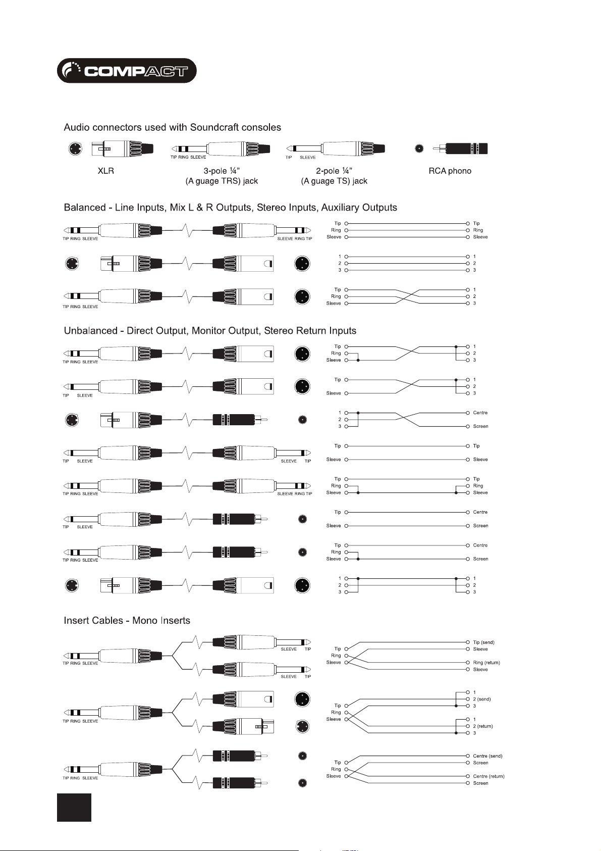
USER GUIDEUSER GUIDE
USER GUIDE
USER GUIDEUSER GUIDE
TYPICAL CONNECTING LEADSTYPICAL CONNECTING LEADS
TYPICAL CONNECTING LEADS
TYPICAL CONNECTING LEADSTYPICAL CONNECTING LEADS
40
Page 41

USER GUIDEUSER GUIDE
USER GUIDE
USER GUIDEUSER GUIDE
TYPICAL CONNECTING LEADSTYPICAL CONNECTING LEADS
TYPICAL CONNECTING LEADS
TYPICAL CONNECTING LEADSTYPICAL CONNECTING LEADS
41
Page 42

USER GUIDEUSER GUIDE
USER GUIDE
USER GUIDEUSER GUIDE
SYSTEM BLOCK DIAGRAMSYSTEM BLOCK DIAGRAM
SYSTEM BLOCK DIAGRAM
SYSTEM BLOCK DIAGRAMSYSTEM BLOCK DIAGRAM
42
Page 43

USER GUIDEUSER GUIDE
USER GUIDE
USER GUIDEUSER GUIDE
GAIN STRUCTURE DIAGRAMGAIN STRUCTURE DIAGRAM
GAIN STRUCTURE DIAGRAM
GAIN STRUCTURE DIAGRAMGAIN STRUCTURE DIAGRAM
43
Page 44

USER GUIDEUSER GUIDE
USER GUIDE
USER GUIDEUSER GUIDE
COMPACT4 CONTROL POSITION MARK-UP SHEETCOMPACT4 CONTROL POSITION MARK-UP SHEET
COMPACT4 CONTROL POSITION MARK-UP SHEET
COMPACT4 CONTROL POSITION MARK-UP SHEETCOMPACT4 CONTROL POSITION MARK-UP SHEET
To assist you in restoring the console to a previous setting you may copy this sheet as many times as you like, and use the copies to make
a note of your control settings.
44
Page 45
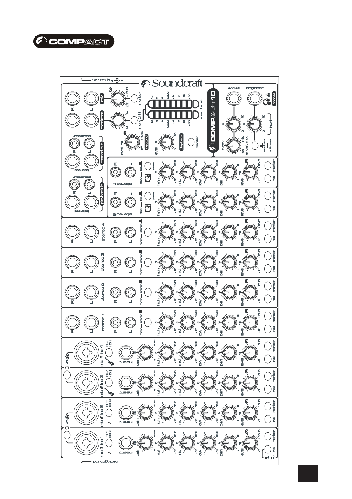
USER GUIDEUSER GUIDE
USER GUIDE
USER GUIDEUSER GUIDE
COMPACT10 CONTROL POSITION MARK-UP SHEETCOMPACT10 CONTROL POSITION MARK-UP SHEET
COMPACT10 CONTROL POSITION MARK-UP SHEET
COMPACT10 CONTROL POSITION MARK-UP SHEETCOMPACT10 CONTROL POSITION MARK-UP SHEET
To assist you in restoring the console to a previous setting you may copy this sheet as many times as you like, and use the copies to make
a note of your control settings.
45
Page 46

USER GUIDEUSER GUIDE
USER GUIDE
USER GUIDEUSER GUIDE
NOTES SHEETNOTES SHEET
NOTES SHEET
NOTES SHEETNOTES SHEET
Please use the following pages to make any notes specific to the operation of your console to act as reminders, or guides for other users:
46
Page 47

USER GUIDEUSER GUIDE
USER GUIDE
USER GUIDEUSER GUIDE
47
Page 48

USER GUIDEUSER GUIDE
USER GUIDE
USER GUIDEUSER GUIDE
intentionally blankintentionally blank
intentionally blank
intentionally blankintentionally blank
48
 Loading...