

Page 1

BROADWAY Contents 1
Page 2

2 BROADWAY Contents
© Harman International Industries Ltd. 1998
All rights reserved
Parts of the design of this product may be protected by worldwide patents.
Part No. ZM0182
Issue 1
Soundcraft is a trading division of Harman International Industries Ltd.
Information in this manual is subject to change without notice and does not represent a commitment on the part of the vendor. Soundcraft shall not be liable for
loss or damage whatsoever arising from the use of information or any error contained in this manual.
No part of this manual may be reproduced, stored in a retrieval system, or transmitted, in any form or by any means, electronic, electrical, mechanical, optical,
chemical, including photocopying and recording, for any purpose without the
express written permission of Soundcraft.
It is recommended that all maintenance and service on the product should be carried out by Soundcraft or its authorised agents. Soundcraft cannot accept any liability whatsoever for any loss or damage caused by service, maintenance or repair
by unauthorised personnel.
Harman International Industries Limited.
Cranborne House,
Cranborne Road,
Cranborne Industrial Estate,
Potters Bar,
Herts.,
EN6 3JN
UK.
Tel: 01707 665000
Fax: 01707 660482
Page 3

BROADWAY Contents i
CCoonntteennttss
1 Introduction 1.1
Live Sound 1.2
System Overview 1.3
2 Installation 2.1
Dimensions and Configurations 2.2
Precautions and Safety Instructions 2.3
Mains Installation 2.4
Connections 2.5
3 Components Of The System 3.1
Input Audio Rack 3.2
Output Audio Rack 3.4
Input Control Surface 3.5
Master Control Surface 3.9
VCA Extender Surface 3.12
4 Running The System 4.1
The Network 4.2
Booting The System 4.3
Fader Tray 4.4
The Assignable Channel Strip 4.5
Master Surface 4.15
Outputs 4.19
5 Touchscreen Functions 5.1
General Syntax 5.2
Cue List 5.3
MIDI Event Lists (MEL's) 5.6
BBRROOAADDWWAAYY
Page 4

ii BROADWAY Contents
Setup 5.16
Solo T/B 5.20
Detect network 5.22
Audio Diagnostics 5.23
Dual Network 5.25
6 AUTOMATION 6.1
Overview 6.2
Terminology 6.3
Creating Cues 6.4
Renumbering 6.5
Replaying Cues 6.6
Replay Scope 6.7
Preview 6.9
7 Playing Back Cues and Mixing 7.1
The Cursor, and Non-Sequential Cues 7.3
The [NEXT] Predictor 7.4
Mixing 7.5
Offsets 7.6
Selectively Copying Data Between Cues 7.8
GrAuxes and Matrices 7.10
8 Hints and Tips 8.1
Setting Up A Show 8.3
Fader Reassignment 8.4
Sensible Arrangement 8.4
Problem-Solving 8.6
More Flexibility In The Hardware 8.6
9 Software Update Policy 9.1
Software Upgrade Notes 9.2
10 Surface Fader Calibration 10.1
Appendix A A.1
Introduction A.2
What is a Control System? A.3
Enter HCA A.4
System Overview A.6
Conclusion A.10
Page 5

BROADWAY Introduction 1.1
BBRROOAADDWWAAYY
IInnttrroodduuccttiioonn
Page 6

1.2 BROADWAY Introduction
LLiivvee SSoouunndd
There is an awkward paradox at the heart of live sound mixing today.
On the one hand, there is a growing requirement in live sound for reset automation and repeatability in the increasingly technical environment of the Live Event.
Not only does the sound designer need to be able to reset and re-route channels
reliably during the evening to get the most out of the available resources, but
there is now a need for integrated control over external devices such as FX units,
Playback and outboard processing. Engineers and operators are becoming sidetracked from mixing duties by the need to set up, reset, trigger and check all these
extra parameters, both inside the console, and externally.
All live engineers know that immediacy of control and ease of use in a high-pressure situation are of paramount importance for any piece of live sound equipment.
There is no point in developing a highly complex automation system if the engineer can no longer creatively mix the show without worrying about complex
operational tasks and special software requirements.
Secondly, the number of radio microphones in use on even quite basic shows is
constantly increasing, and conventional console frames are having to be extended
to allow for more and more input channels.
To further complicate matters, the Producer or venue owner will not want to give
up any more seats than is absolutely necessary.
Broadway is our answer to these changing needs. Whilst offering the designer a
high level of reset, programmability, outboard control and flexibility, Broadway
remains very simple for the engineer or operator to use on a daily basis, and furthermore can be configured to take up much less space than a conventional console of an equivalent number of inputs.
Once Broadway has been set up for even the most demanding live show, the main
operational areas of the console - the fader trays, the channel strip and the metering - are sufficiently familiar to allow the operator to get on with the task of creatively mixing the show, while the mundane daily switching and routing functions
are performed by the console on a scene-by scene basis.
Page 7
BROADWAY Introduction 1.3
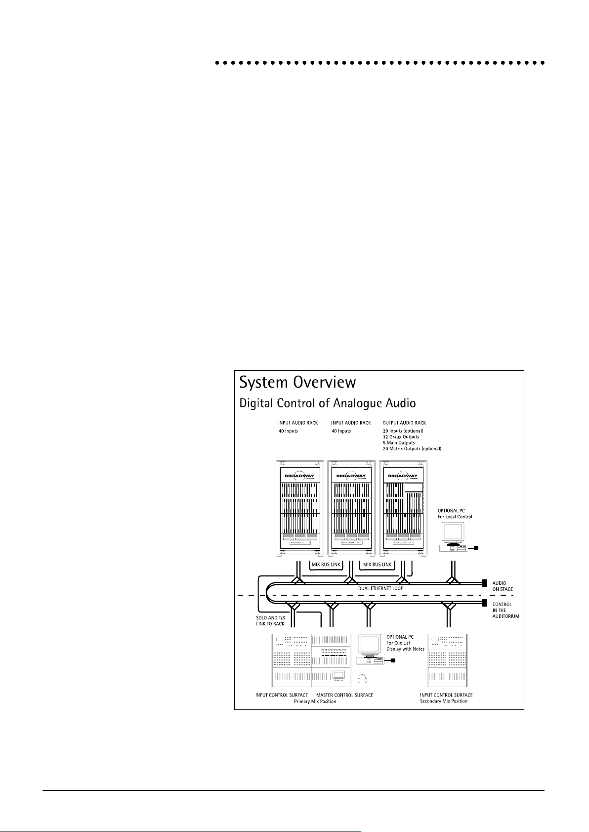
SSyysstteemm OOvveerrvviieeww
The Broadway system is based upon an X into 32 + 5 into X configuration. This
means that the console will support potentially any number of inputs, mixed onto
32 Group / Aux (GrAux) send busses, from which a matrix of up to 40 outputs
may then be derived.
There are five basic building blocks for any Broadway system:
l Input Audio Rack
l Master Audio Rack
l Input Control Surface
l Master Control Surface
l VCA Extender Surface
The above units may be arranged in any order or physical location, but must be
interconnected via the Ethernet Network. Every element, or Node, on the
Network is a stand-alone unit. Each has its own Power Supply (dual redundant
in the racks), and a Processor Card for data processing and Network connectivity.
Please see Running The System below for a more detailed description of
Network Functionality and system boot procedure.
Page 8

1.4 BROADWAY Introduction
Page 9

BROADWAY Installation 2.1
BBRROOAADDWWAAYY
IInnssttaallllaattiioonn
Page 10

2.2 BROADWAY Installation
DDiimmeennssiioonnss aanndd CCoonnffiigguurraattiioonnss
Page 11

BROADWAY Installation 2.3
PPrreeccaauuttiioonnss aanndd SSaaffeettyy IInnssttrruuccttiioonnss
GGeenneerraall PPrreeccaauuttiioonnss
Avoid storing or using the system in conditions of excessive heat or cold, or in
positions where it is likely to be subject to vibration, dust or moisture. Do not use
any liquids to clean the fascia of the unit: a soft dry brush is ideal. Use only water
or ethyl alcohol to clean the trim and scribble strips. Other solvents may cause
damage to paint or plastic parts.
Avoid using the console close to strong sources of electromagnetic radiation (e.g.
video monitors, highpower electric cabling): this may cause degradation of the
audio quality due to induced voltages in connecting leads and chassis.
Caution!
In all cases, refer servicing to qualified personnel.
HHaannddlliinngg aanndd TTrraannssppoorrtt
Be sure to disconnect all cabling before moving. At all times avoid applying excessive force to any knobs, switches or connectors.
PPoowweerr SSuupppplliieess
The power supplies in the racks are auto adjusting for mains input voltages. The
power supplies in the control surfaces are user switchable between 2 input voltages: nominally 115V AC and 230V AC.
In all cases ensure that the correct fuses are used. The values required
are clearly shown on the appropriate fascias.
SSiiggnnaall LLeevveellss
It is important to supply the correct input levels to the racks, otherwise signal to
noise ratio or distortion performance may be degraded; and in extreme cases,
damage to the internal circuitry may result. Likewise, on all balanced inputs avoid
sources with large commonmode DC, AC or RF voltages, as these will reduce the
available signal range on the inputs. Note that 0dBu = 0.775V RMS.
The microphone inputs are designed for use with balanced low impedance (150 or
200 ohms) microphones.
Caution!
DO NOT use unbalanced microphones or battery powered condenser
microphones without isolating the +48V phantom power: degraded per-
formance or damage to the microphone may result.
The sensitivity of the Mic inputs is variable from +4dBu to -66dBu, with a maximum input level of +25dBu. The Line Input sensitivity is variable from +14dBu to
-46dBu with a maximum input level of +35dBu.
Page 12

2.4 BROADWAY Installation
MMaaiinnss IInnssttaallllaattiioonn
WWiirriinngg CCoonnssiiddeerraattiioonnss
A For optimum performance it is essential for the earthing system to be clean
and noise free, as all signals are referenced to this earth. A central point
should be decided on for the main earth point, and all earths should be
star-fed from this point. It is recommended that an individual earth wire
be run from each electrical outlet, back to the system star point to provide
a safety earth reference for each piece of equipment.
B Install separate mains outlets for the audio equipment, and feed these inde-
pendently from any other equipment.
C Avoid locating mains distribution boxes near audio equipment, especially
tape recorders, which are very sensitive to electromagnetic fields.
D Where possible ensure that all audio cable screens and signal earths are
connected to ground only at their source.
PPoowweerr SSuupppplliieess
Warning!
Before switching on your system, check that the mains voltage selectors
on the control surfaces are set to the correct mains voltage for your area,
and that the fuse is of the correct rating and type. This is clearly marked
on the case of the power supply. Do not replace the fuse with any other
type, as this could become a safety hazard and will void the warranty.
Page 13

BROADWAY Installation 2.5
CCoonnnneeccttiioonnss
Soundcraft part numbers are in italics
MMaasstteerr AAuuddiioo PPFFLL
Console has Neutrik NC5MP 5 pin male XLR connector (FK0933) which mates
with Neutrik NC5FX (FK0934)
Pin Signal
pin 1 Audio Gnd
pin 2 Left channel +
pin 3 Left channel -
pin 4 Right channel +
pin 5 Right channel -
MMaasstteerr AAuuddiioo -- RRaacckk AAuuddiioo MMuullttiiccoorree
Console & Rack have ITT Cannon 23 pin Trident Ringlock connector part
no.192990-1290 (FF0934).
Mating part: ITT part # 192990-1320 (FF0933).
Need male pins 192990-0080 (FG0664) for both ends of audio cable
Pin Signal
1 PFL1L+
2 PFL1L-
3 CONN
4 PFL1R+
5 PFL1R-
6 AGND
7 PFL2L+
8 PFL2L-
9 PFL2R+
10 PFL2R-
11 PFL3L+
12 PFL3L-
13 PFL3R+
14 PFL3R-
15 CRML+
16 CRML-
17 CRMC+
18 CRMC-
19 CRMR+
20 CRMR-
21 AGND
22 TBOUT+
23 TBOUT-
Note: pin 3 tells the console that the rack is connected.
We recommend Canford Audio FSM12 cable.
Page 14

2.6 BROADWAY Installation
LLiittttlliittee
12V 300mA Halogen type.
Console has 4 pin Neutrik XLR female connector NC4FX
pin 4 +12V dc (300mA)
pin 2& 3 not connected
pin 1 0V (chassis)
Littlite must be at least 18 to reach over ACS.
We recommend Littlite part # 18RXH4
AACCSS
25 pin D-type connector
Wired pin to pin. All pins must be connected - i.e. standard printer cables cannot
be used.
Male part: FB0170 25 pin D-type IDC cable mount
Female part: FB0101
Recommended cable: Thomas & Betts part # 300-25-100
N.B.: maximum cable length we have tried is 10m.
EEtthheerrnneett
Broadway uses 50W BNC (10-base 2) connections (to IEE 802.3)
Recommended cable: RG58BU type (UR43) (LB0119)
Minimum cable length: 3m
Maximum cable length: 100m
Recommended connector: M/A Com part # 115-01-010 (FZ2260)
50W Terminator @ end nodes only: M/A Com part # B35Z98E501X99 (FZ2259)
T-pieces - M/A Com part # 105-03-000 (FZ143768)
AAuuddiioo IInnppuuttss
The audio inputs are via combined XLR/1/4" Jack Neutrik connectors (NCJ6FK).
Page 15

BROADWAY System Components 3.1
BBRROOAADDWWAAYY
CCoommppoonneennttss ooff tthhee
SSyysstteemm
!
Page 16

3.2 BROADWAY System Components
IInnppuutt AAuuddiioo RRaacckk
HHaarrddwwaarree
An Input Audio Rack contains 40 complete inputs, along with all the connectivity
both for the Audio and for the Network. Potentially any number of Input racks
may be added to a Broadway system, each rack adding 40 inputs. The MIX BUS
interconnections are carried via HAN144D 144-pin multiway connectors from
rack to rack, ending up in the Output rack. These connectors must be attached
(using the supplied interconnect cables) to enable audio to pass through the system.
Audio connectivity in the standard console is via Neutrik Combi connectors, which
offer both female XLR and 1/4 TRS Jack sockets. Certain custom consoles will
include HAN144D or EDAC90 multiway connectors in addition to the standard
connectivity.
The inserts are on 1/4 TRS Jacks, are fully balanced, and switchable IN/OUT via
software from the surface.
The electronics inside the rack consist of vertically-mounted PCB boards, and are
divided into three sections - input cards at the top, EQ cards in the middle, and
Mix cards at the bottom. The racks seat twenty cards from left to right, and each
card in the input and EQ sections carries two channels - hence 40 channels per
rack.
Page 17

BROADWAY System Components 3.3
In the lower part of the rack is a sliding tray which contains the dual redundant
power supplies and the processor card. The tray, when removed from the rack,
will break the contact with the rest of the rack, and therefore isolate the supply to
the rack. (1) The Processor card is attached to the front of the rack, and will
therefore be disconnected with the movement of the tray.
The power supplies operate in parallel, but the rack can operate on a single supply
if one should fail. The processor card contains all the network connectivity, and
the MIDI IN / OUT and THRU.
The input racks house 40 inputs each (or 20 inputs if half-filled). The front panels
of the rack are sectionalised and hinged, and may be opened to reveal the Input,
EQ and MIX cards respectively.
A series of led's on the cards show the status of the data and power loops. Green
LED's represent the power, and red the data loop. All power, audio and data
loops are supplied via the backplane connection.
1 Of course, as with any Broadway component, the unit should be isolated from the mains before attempting to remove or modify
any hardware element of the unit.
Page 18

3.4 BROADWAY System Components
OOuuttppuutt AAuuddiioo RRaacckk
HHaarrddwwaarree
The output rack carries all of the GrAux, Main and Matrix outputs for the
Broadway system. It also handles connectivity to the Solo, Talkback and comms
audio on the Master Surface via a 23-pin connector.
The electronics are on vertically-mounted PCB boards, similar to the Input racks.
The cards are divided into two main types - Mix Bus and Quint Output. The
rearcon of the output rack contains all output connectivity including inserts for the
GrAuxes and Matrices. Note that the GrAux inserts may be switched IN/OUT in
software, but the Matrix inserts are broken upon insertion of a jack, and should
therefore be run through a normalised patchbay or processor to maintain the signal.
The power supply and processor are the same as those in the input rack. See the
description in the input audio rack section above.
The output rack handles all bus outputs from, and data routing for, the Broadway
system. Because of this, it is the only potentially vulnerable part of the system, and
it is recommended than an Uninterruptible Power Supply (UPS) be installed on
this unit. As on the Input rack, the front doors of the rack are sectionalised and
hinged, and may be opened to reveal the MIX and QUINT OUTPUT cards inside.
A series of led's on the cards show the status of the data and power loops. Green
LED's represent the power, and red the data loop. All power, audio and data
loops are supplied via the backplane connection.
Page 19

BROADWAY System Components 3.5
IInnppuutt CCoonnttrrooll SSuurrffaaccee
HHaarrddwwaarree
∞
8
8
8
8
8
8
8
8
8
8
8
8
8
8
8
8
8
8
8
8
8
8
The input control surfaces house 20 motorised faders, each with associated Mute,
Solo and SEL(ect) switches, and 4-character dot matrix name displays. There are 8
BANKS of faders available on each Input surface, selectable from the Bank
switches in the centre of the fader tray.
Above these, in the Encoder Tray, are some 120 encoders (6 per channel), which
are assignable to perform any rotary channel strip function.
At the top of the Input Surface is the Assignable Channel Strip (ACS). This offers a
single complete input channel strip, and will display and edit the parameters of the
SEL(ect)ed channel. The ACS is removable, and may be carried up to approximately 100 metres away from the console for more effective console setup, allowing the user to listen in different areas of an auditorium whilst making changes.
The rear panel of the input surface offers IEC mains input, the main power switch,
voltage selection, fader and main power fuses, serial and barcode number labels,
and the local connector to the ACS.
The Input Surface also has two removable trays in the rear panel : a Power
Supply and a Processor Card. These trays may be removed by the user when servicing or upgrading the surface. The power supply tray, once mated with the
power distribution backplane inside the Surface, organises the routing of appropriate power to the relevant areas of the unit.
The processor tray contains the main processing power of the surface, and contains all the interconnection ports required for network and system connection:
C3, ESBUS, MIDI IN, OUT, THRU, and BNC network connections.
Page 20

3.6 BROADWAY System Components
FFuunnccttiioonnaall DDeessccrriippttiioonn -- MMooddeess
Input Control Surfaces operate in one of four modes. These modes dictate the
functions performed by the hardware and software, and are selected via the three
Mode switches in the centre of the Input surface.
Though the Input surface is normally used to control the levels, EQ, and routing of
any twenty input channels, it may alternatively be used as the control surface for
GrAux (Group / Aux) or Matrix outputs, enabling inputs, effects sends, foldback
feeds and group to matrix mixes to be set up from a single control surface. A
fourth mode enables the 20 faders on the Input surface to be used as 20 VCA
master faders, giving the user access to all 20 VCA groups on a single surface.
IInnppuutt MMooddee
The most basic of the four modes is Input mode. In this mode, the surface offers
complete control over up to 8 Banks of 20 inputs (i.e. 160 channels).
AACCSS
The Assignable Channel Strip gives the operator a view of every function of a particular stereo or mono input channel, simply by pressing the SEL (ect) button on
that channel. Dedicated controls are offered for every function, with the GrAux
routing controlled by sixteen groups of controls which may be selected to represent GrAux 1-16 or 17-32. Each GrAux is identified by name by the four-digit displays above each control. The four-band fully parametric EQ is accessed by dedicated rotary controls and displays; this may be displayed in graphical form on the
ACS LCD screen. This display is also used to identify the channel being affected by
the ACS, and may be used in conjunction with the four multi-function rotary controls and switches for a variety of further facilities.
Panning is provided between any combination of the five main busses, enabling
true LCR, LCRS and quad images to be created. Dual meters are provided for use
where channels are linked in stereo.
The ACS is normally located at the top of each Input Control Surface, but may be
demounted and used remotely, connected to the main surface via a simple multiway cable. Since the currently selected channel may be changed on the ACS itself,
and the majority of functions accessed from this small panel, this facility enables
the user to take the console into the auditorium, and set up level sends, EQ etc.
whilst seated where it really matters - i.e. where the audience will be.
The channel under the control of the ACS may be isolated from the rest of the
console so that it will not respond to changes caused by recalling new scenes, and
may be locked to prevent another operator from inadvertently selecting a different channel to act under ACS control.
Page 21

BROADWAY System Components 3.7
EEnnccooddeerr PPaanneell
This section of the Input Control Surface contains six assignable rotary controls for
each of the channels displayed. Indication of EQ, Inserted Dynamics (2) and Stereo
status are provided, as well as a four-digit display showing the name or number of
each channel. Each row of controls acts on a single function of the twenty inputs,
such as GrAux sends, EQ parameters, or input gain: the function of the rows may
be scrolled using ì and Å. The eight Control Assignment buttons located on
the Master section are 8 user-programmable memory locations, into which the
operator may store 8 favourite arrangements of the Input Surface Encoder Tray
(i.e. 8 Views of chosen functions).
The function of a particular row may be locked to prevent its deselection, and
any channel may be isolated to protect it from scene changes.
FFaaddeerr PPaanneell
The fader panel is the last of the three component sections of the input control
surface. A SOLO button is located below each of the faders. This button operates
much as the Solo on a conventional desk. The primary metering for each channel
is adjacent to the 100mm motorised fader.
The twin seven-segment LED's above each fader display the VCA to which the
channel is currently assigned, or, if multiple VCA's have been assigned, the Primary
VCA (i.e. the lowest-numbered) is shown, and a decimal point appears after the
second numeric.
The SEL(ect) button is used to bring the relevant channel up onto the ACS. This
button is also used for various channel interrogation and configuration functions.
These modes are selected from the touchscreen in the Master Section. The
MUTE button operates as on a conventional console, muting all sends from that
channel, although there is a facility for each GrAux which allows the user to set
that buss to Pre-Mute when it's Pre-Fade. If the GrAux is set as Pre-Mute, the
MUTE switch on the Input strip will have no effect on the pre-fade GrAux sends
from that channel. This is the default setting.
GGrrAAuuxx MMooddee
Normally used in Input mode, if the Input Control Surface is selected to GrAux
mode, the 20 faders become the first 20 (or, on bank two, the last 12) GrAux
master faders, and the six rows of encoders above each fader become the sends
from that GrAux INTO the appropriate matrices.
AACCSS
In GrAux mode, the ACS will control routing of the currently selected GrAux to
any of the Matrix outputs. The 16 send encoders will now carry the names of
the Matrices, and will allow send levels to the first 16 matrices to be set, and the
first touch of [SWAP] will bring up Matrices 17-32. A third, fourth etc. touch of
SWAP will bring up 33-X, where X is the number of Matrix outputs. Insert In/Out,
Fader level, Mute, Metering and Solo will all function as before, but all other functions will be disabled. The LCD may be used to change the currently-selected
GrAux. The 5 main output switches and the PAN function will act as before, and
will allow GrAuxes to be routed to the MAIN OUTPUTS.
2 Integrated dynamic processing was not available at the time of writing, but all surfaces have been designed to cope with the
arrival of this functionality should the need arise, either in the Broadway itself, or via remote control (see AppendixA).
Page 22

3.8 BROADWAY System Components
MMaattrriixx MMooddee
Conversely, in Matrix mode, the 20 faders become the first 20 matrix masters,
and the rotaries display and edit the contributions FROM the appropriate
GrAuxes, scrollable through all GrAuxes as required.
AACCSS
In Matrix mode, the ACS will set feeds to the currently selected Matrix from any
of the GrAux outputs. The 16 draw encoders will allow levels from the first 16
GrAuxes to be set, and the first touch of [SWAP] will bring up GrAuxes 17-32.
Fader level, Mute, Metering and Solo will all function as before, but all other functions will be disabled. The LCD may be used to change the currently-selected
Matrix.
VVCCAA MMooddee
VCA mode puts the 20 VCA groups onto the 20 input surface faders, with the first
4 non-zero characters of the VCA group name appearing above the appropriate
faders.
When the input surface is in VCA mode, the ACS may still be used to select and
edit input channels, as long as CHAN HOLD is selected on the ACS.
WWhhyy BBootthheerr WWiitthh MMooddeess??
These modes, combined with the assignability of the console, allow the full audio
path of the largest possible system (100+ into 32+5 into 40+) from input to
matrix output, to be controlled from a single 600 x 800mm footprint Input
Control Surface. This is the extreme, of course, and most users will doubtless
choose to have more Input Surfaces to have greater visibility at any given time, but
the flexibility to have all or just 20 channels visible depending on space, financial
resources etc., allows the designer and producer of a show to work together to
provide a desirable but affordable audio system.
It might be appropriate to have, say, 60 physical faders during the production period, and just 20 when the show is up and running, thus reducing running costs once
the design has settled down. The spare Input Surfaces could then be placed back
into hire stock, and sent out with a different Master Surface for the next event.
Page 23

BROADWAY System Components 3.9
STEREO STEREOSTEREOSTEREO STEREO STEREO STEREO STEREO STEREO STEREO STEREO STEREO STEREO STEREO STEREO STEREO STEREO STEREO STEREO
1357911131517192123252729312468101214161820222426283032
LCR
+10dB
5
-
-
10
0
−
∞
10
9
7
6
5
4
3
2
1
0
8
10
9
7
6
5
4
3
2
1
0
8
+10dB
5
-
-
10
0
−
∞
+10dB
5
-
-
10
0
−
∞
+10dB
5
-
-
10
0
−
∞
+10dB
5
-
-
10
0
−
∞
+10dB
5
-
-
10
0
−
∞
+10dB
5
-
-
10
0
−
∞
+10dB
5
-
-
10
0
−
∞
+10dB
5
-
-
10
0
−
∞
+10dB
5
-
-
10
0
−
∞
+10dB
5
-
-
10
0
−
∞
+10dB
5
-
-
10
0
−
∞
+10dB
5
-
-
10
0
−
∞
+10dB
5
-
-
10
0
−
∞
+10dB
5
-
-
10
0
−
∞
+10dB
5
-
-
10
0
−
∞
8
888
888
8
8
8
8
8
888
8
888
8
8
8
8
8
8
8
8
8
MMaasstteerr CCoonnttrrooll SSuurrffaaccee
HHaarrddwwaarree
The Master Surface provides all the necessary hardware for control over the 32
GrAux outputs, the 5 Main outputs and the Matrix outputs (if fitted).
The fader tray contains 8 VCA Master Faders, with 8-character dot matrix name
displays and associated SOLO and MUTE switches. There are also 8 BANK master
switches and 8 Preset switches.
To the right of the VCA faders lies the touchscreen and associated page and cue
control switches. This area is dedicated to the sceneset automation system, and is
described in more detail in the Sceneset Automation section below.
Above the fader tray is the GrAux Fader Panel, which contains 16 Faders for the
GrAuxes and 4 Faders for the five Main Outputs (this will be explained later).
The top section of the Master Surface houses the Metering for the 32 GrAux outputs and the 5 Main outputs. It also carries the talkback and communications
switches.
Page 24

3.10 BROADWAY System Components
FFuunnccttiioonnaall DDeessccrriippttiioonn
MMeetteerrbbrriiddggee
This allows metering of all 32 GrAuxes, plus the main outputs. Via a MTX METER
switch, it is also possible to swap the GRAUX meter section to display 32 matrix
outputs. The STEREO led below each pair of matrices denotes that the pair of
GRAUX or MATRIX outputs is linked into stereo.
MASTER MUTE sets all MUTE switches on the system to MUTE ON. This function is disabled in LIVE mode.
LIVE locks out those functions which could be detrimental to a live performance,
such as MASTER MUTE, talkback, solo in place and cue editing.
GGrrAAuuxx FFaaddeerr PPaanneell
These controls allow access to the 32 GRAUX or MATRIX outputs (switchable
GRAUX/MATRIX in banks of 16). The first 16 outputs are controlled via faders,
and the last 16 are available on rotary encoders. Each output has a 4-character
LED matrix display for name information, a MUTE button, a FUNC (tion) button,
and a SOLO button. SOLO operates as on the input faders. The FUNC button
toggles the current function on or off - the function mode being selected via the
four FUNC buttons to the left of the 16 GRAUX master faders. When in INS
mode, for example, the FUNC button toggles the insert IN/OUT for its associated
output. For a full description of the FUNC switch, please see 4.5.2 below.
Talkback and Monitoring functions are available from this panel. All master outputs, two external inputs plus the listen mic may be monitored, with a self-cancelling or additive law, depending upon function. Talkback may be performed with
an External system, a monitor desk, the audio racks and the comms loop. The
user may set up talkback to desired GrAuxes and Matrices, via the use of the
FUNC button in TB ASSN mode. TALK TO BUSS then arms all the relevant outputs for talkback.
In addition to the 16 GRAUX faders, there are four Master Output faders, controlling outputs 1, 2, 3, and 4/5. The last fader is paired to facilitate stereo surround level setting.
The 8 control assignment buttons allow the user to store 8 user-defined arrangements of the 6 assignable encoders on the input surfaces.
Page 25

BROADWAY System Components 3.11
VVCCAA FFaaddeerr PPaanneell
This houses the 8 VCA faders. Of course, being a digital control system, the term
VCA on the control surface is not strictly correct - these are master faders for
links or groups of other faders, and the value of the master fader will be added
to all slave faders. Each input or GrAux fader may be assigned to one or more of
the 20 VCA groups per cue. The seven-segment display above each of the input
faders will show the primary VCA to which that input is assigned - that is, the
lowest numerical value VCA. If the input is assigned to more than one VCA, a
small dot is illuminated in the bottom right-hand corner of the seven-segment display to denote multiple assignment. So, if an input were assigned to VCA's 1 and 3,
the display would show 1.. The details of hidden VCA assignments may be
seen by SEL(ect)ing the appropriate channel, and using the VCA section of the
ACS to display the current VCA status.
It is also possible to set any or all of the 8 VCA faders to generate outgoing MIDI
continuous controller information, to be sent via any MIDI OUT port on the system (each unit on the network has its own discrete set of MIDI ports).
An eight-character dot matrix display is housed above each of the 8 faders for
name information, or to display the current MIDI continuous controller assigned
to that fader. The SOLO and MUTE switches above the VCA faders will solo or
mute all channels under the control of that fader.
To the right of the 8 VCA faders lies the Cross-Fader (X-FADE). This allows the
user to create a smooth transition from the parameters of one cue to those of
another. This transition may be automated, or performed manually by the user.
Touching the X-FADEr during an automated crossfade will result in the user taking manual control of that fade.
8
8
8
8
8
8
8
8
Page 26

3.12 BROADWAY System Components
VVCCAA EExxtteennddeerr SSuurrffaaccee
HHaarrddwwaarree
The VCA Extender surface is based on the Input Surface frame, with faders in the
lower tray and a removable meterbridge in the upper section (where the ACS
lives on the Input Surface).
It is intended to offer the power user a number of functions designed to streamline the programming and mixing of a large system. The hardware comprises:
AA ffaaddeerr ttrraayy,, ccoonnttaaiinniinngg::
l 12 VCA Faders, with associated SOLO and MUTE switches, 8-character
displays for naming, and RANGE and VCA LEDs (all as per Master Surface
VCA section)
l 1 Crossfader with associated X-FADE switch
l [NEXT], [LAST] (covered) and (Pre)VIEW buttons
l 8 Global Bank Select buttons
AA cceennttrree ttrraayy,, ccoonnttaaiinniinngg::
l An embedded PC
l 3.5 Disk Drive
AA mmeetteerr bbrriiddggee,, ccoonnttaaiinniinngg::
l 20 meters, 16 LEDs + peak each with an associated 4-character matrix dis-
play, a POST (amber) LED, a STEREO (GREEN) LED and a MUTE switch
(with RED LED)
l Three 8-character matrix displays sited adjacent to each other, and a pair of
associated function switches (with red and green LEDs)
FFuunnccttiioonnaall DDeessccrriippttiioonn
FFaaddeerr TTrraayy
Broadway allows 20 VCA groups per cue. The VCA faders will function as VCAs
9-20 in the system (VCAs 1-8 are present on the Master Surface faders). The
crossfader is to the right of the 12 VCA faders. Operation of these faders is exactly
as per the Master Surface VCAs.
The [NEXT], [LAST] (covered) and VIEW switches are to the right of the faders,
and are aligned vertically. [NEXT] is at the bottom, then [LAST] (covered) and
VIEW at the top. These switches are illuminated, and function as per those on the
Master Surface.
Global BANK select switches operate as per those on the Master Surface.
CCeennttrree SSeeccttiioonn
The PC, mounted flush with the surface, is for use with the Broadway PC software, and sockets in the rear panel of the surface will allow for the connection of
mouse/trackball and keyboard. The PC is offset to the left of the centre section to
allow for the use of a mouse or small keyboard to the right. The mounting of the
PC is very low-profile to allow scripts, folders etc. to be laid on top when the PC
is not required.
Page 27

BROADWAY System Components 3.13
MMeetteerrbbrriiddggee
This offers 20 assignable meters, each with an associated name, pre/post-fade status and stereo LEDs. The assignments of the 20 meters is stored when a console
snapshot is taken, and recalled as appropriate with each cue.
The meters may monitor signal level for any console Input, or any Graux or Matrix
output. They follow the same law (and, of course, the same value!) as the meter
on the channel being monitored at all times.
The pre/post led is labelled POST, and will only illuminate when the meter on the
channel being monitored has been assigned to post-fade (the exception rather
than the norm, keeping the number of illuminated LEDs to a minimum at any
time).
The STEREO led illuminates when the channel being monitored has been assigned
to be stereo. In this case, the meter shows the peak signal of both meters.
The MUTE switches below the meters will MUTE the appropriate channel. it will
perform the function exactly as would the MUTE switch on the channel itself, and
is directly software-linked to that switch (i.e. will be illuminated when the local
channel MUTE is activated).
The 24-character display bar (i.e. 3 x 8-character displays), will display the current
scene name in run-time, and is used for assignment of the meters when the appropriate edit mode is selected (via the touchscreen and PC software).
In normal operation, the two function switches beside the display will operate as
[NEXT]/[LAST] switches. [LAST] will be the left function switch, [NEXT] will be
the right function switch. < and > respectively will be on the leftmost and
rightmost extremes of the display to denote the function of the switches. In this
mode, the GREEN LEDs are illuminated.
EEddiitt MMooddee
The assignments of the meters may be set up in one of three ways -
1. Via the touchscreen. A dedicated touchscreen page (on the master surface) lists the meters (1-20). The assignment of channels to meters may be
performed in the same way as assignment of inputs to faders - i.e., each
meter number will have a name beside it - the currently monitored channel. Touching the name will bring up a list of all the possible entries, and the
jog wheel / screen arrows will scroll through the options until [EXECUTE]
or CANCEL is pressed.
2. Via the PC. Similar to the touchscreen method, but running on the PC
software.
3. Via the 24-character display on the meterbridge. When the surface is
put into EDIT mode (via the touchscreen or PC software), the leftmost display shows XXXX to denote that this is the meter to be edited. The 24character display will now show the meter number (in this case 1) and
the name of the currently-monitored channel. The two function keys
beside the display select for editing the meter to the left or right of the current meter.
The leftmost and rightmost extremes of the display should show < and >
respectively to denote the function of those switches. The RED LEDs should be
illuminated when the user enters EDIT mode. When a meter is active for editing,
the action of SELecting a channel (input or output) on the system will place that
channel on the currently-selected meter. The assignments of channels to meters
will be stored and recalled along with the rest of the cue information.
Page 28

3.14 BROADWAY System Components
 Loading...