

Page 1

Page 2
© Harman International Industries Ltd. 1997, 1998
All rights reserved
Parts of the design of this product may be protected by worldwide patents.
Part No. ZM0215
Issue 1
Soundcraft is a trading division of Harman International Industries Ltd.
Information in this manual is subject to change without notice and does not repre-
sent a commitment on the part of the vendor. Soundcraft shall not be liable for
loss or damage whatsoever arising from the use of information or any error con-
tained in this manual.
No part of this manual may be reproduced, stored in a retrieval system, or trans-
mitted, in any form or by any means, electronic, electrical, mechanical, optical,
chemical, including photocopying and recording, for any purpose without the
express written permission of Soundcraft.
It is recommended that all maintenance and service on the product should be car-
ried out by Soundcraft or its authorised agents. Soundcraft cannot accept any lia-
bility whatsoever for any loss or damage caused by service, maintenance or repair
by unauthorised personnel.
Harman International Industries Limited.
Cranborne House,
Cranborne Road,
Cranborne Industrial Estate,
Potters Bar,
Herts.,
EN6 3JN
UK.
Tel: 01707 665000
Fax: 01707 660482
Page 3

BB440000
CCoonntteennttss
1.Introduction 1.1
Introduction 1.2
Warranty 1.3
2.Installation 2.1
Dimensions 2.2
Earthing the Console 2.3
Meterbridge 2.3
Rear Connector Panel EDAC Connectors 2.4
Rear Connector Panel D-type Connectors 2.6
Jumper Options 2.8
Internal Monitor Source Selection 2.11
Block Diagrams 3.1
Mono Input Module 3.2
Stereo Input Module 3.3
Mono Group Module 3.4
Stereo Master Module 3.5
Communications Module 3.6
Monitor Module 3.7
Functional Description 4.1
Mono Input Module 4.2
Stereo Input Module 4.6
Mono Group Module 4.10
Stereo Group Module 4.14
Stereo Master Module 4.18
Communication Module 4.21
Monitor Module 4.24
B400 Contents i
Page 4

ii B400 Contents
Specifications 5.1
B400 Typical Specifications 5.2
Page 5

B400 Introduction 1.1
BB440000
IInnttrroodduuccttiioonn
1
Page 6

1.2 B400 Introduction
IInnttrroodduuccttiioonn
Congratulations on purchasing a Soundcraft console.
The B400 has been designed to meet the needs of Live TV & Radio Broadcast and
Production Facilities including OB vehicles. Based on the highly successful B800,
the B400 delivers a level of configurability unrivalled in its class.
SSyysstteemm OOvveerrvviieeww
l 24, 32, 40, 48 and 56-module frames
l 1 stereo and 3 mono auxes
l LED indication on all switches
l Wide variation in module audio and logic / control functions via internal
jumpers
l Stereo ISDN cleanfeed facilities via direct outputs on Telco channels
l Versatile and highly configurable monitoring via speakers and studio and
guest headphones
l Limiters on master output
l Wide range of meterbridge options
l Balanced audio inputs and outputs throughout, on XLRs and EDACs
l Pseudo-balanced internal bussing
Page 7

B400 Introduction 1.3
PPoowweerr SSuuppppllyy
l The B400 uses the CPS275 Power Supply.
WWaarrrraannttyy
1 Soundcraft is a trading division of Harman International Industries Ltd .
End User means the person who first puts the equipment into regular
operation.
Dealer means the person other than Soundcraft (if any) from whom the
End User purchased the Equipment, provided such a person is authorised
for this purpose by Soundcraft or its accredited Distributor.
Equipment means the equipment supplied with this manual.
2 If within the period of twelve months from the date of delivery of the
Equipment to the End User it shall prove defective by reason only of faulty
materials and/or workmanship to such an extent that the effectiveness
and/or usability thereof is materially affected the Equipment or the defec-
tive component should be returned to the Dealer or to Soundcraft and
subject to the following conditions the Dealer or Soundcraft will repair or
replace the defective components. Any components replaced will become
the property of Soundcraft.
3 Any Equipment or component returned will be at the risk of the End User
whilst in transit (both to and from the Dealer or Soundcraft) and postage
must be prepaid.
4 This warranty shall only be available if:
a) the Equipment has been properly installed in accordance with instruc-
tions contained in Soundcrafts manual; and
b) the End User has notified Soundcraft or the Dealer within 14 days of the
defect appearing; and
c) no persons other than authorised representatives of Soundcraft or the
Dealer have effected any replacement of parts maintenance adjustments or
repairs to the Equipment; and
d) the End User has used the Equipment only for such purposes as
Soundcraft recommends, with only such operating supplies as meet
Soundcrafts specifications and otherwise in all respects in accordance
Soundcrafts recommendations.
5 Defects arising as a result of the following are not covered by this
Warranty: faulty or negligent handling, chemical or electro-chemical or
electrical influences, accidental damage, Acts of God, neglect, deficiency in
electrical power, air-conditioning or humidity control.
6 The benefit of this Warranty may not be assigned by the End User.
7 End Users who are consumers should note their rights under this Warranty
are in addition to and do not affect any other rights to which they may be
entitled against the seller of the Equipment.
Page 8

1.4 B400 Introduction
Page 9

B400 Installation 2.1
BB440000
IInnssttaallllaattiioonn
2
Page 10

2.2 B400 Installation
DDiimmeennssiioonnss
24-Module 833.72mm / 32.82"
32-Module 1087.72mm / 42.82"
40-Module 1341.72mm / 52.82"
48-Module 1595.72mm / 62.82"
56-Module 1849.72mm / 72.82
Page 11
B400 Installation 2.3
EEaarrtthhiinngg tthhee CCoonnssoollee
Important Notice.
The console has two earth posts on the rear connector panel. They are located
near to the power supply connectors. The un-insulated metal post is the chassis
ground, and the insulated post is the system ground. The console is supplied with
these two posts linked together. It is essential that the console is operated with
these two earths linked. They may, however, be linked at a different point in the
installation: for example, a technical earth in the installation site. In this case the
wire link between the two posts must be removed.
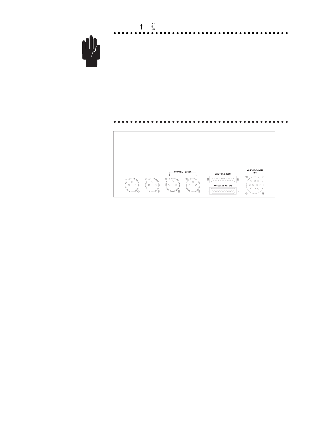
MMeetteerrbbrriiddggee
The meterbridge has a number of connectors as shown below:
The MONITOR/COMMS D-type connector routes signals to the Monitor Selector
PCB ( see the Meterbridge connector list on the previous page for pin details).
The ANCILLARY METERS D-type connector carries the Groups and Auxes into
the meterbridge. The actual connections used will depend on the number of ancil-
lary meters which are fitted. The connections are:
1 Ground 14 Ground
2 Group 8 15 Group 7
3 Group 6 16 Group 5
4 Group 4 17 Group 3
5 Group 2 18 Group 1
6 Not Used 19 Not Used
7 Not Used 20 Not Used
8 21 Aux 1
9 22 Aux 2
10 23 Aux 3
11 24
12 Aux 4L 25 Aux 4R
13 Not Used
The EXTERNAL INPUTS XLRs are also routed to the Monitor Selector PCB. The
inputs here may be monitored on the Meters which are associated with the
Monitor Selector PCB.
There are also 2 additional XLRs: these are for future expansion.
Page 12

2.4 B400 Installation
RReeaarr CCoonnnneeccttoorr PPaanneell EEDDAACC CCoonnnneeccttoorrss
There are two female 90-way EDAC connectors on the rear connector panel. The
illustration below shows the pin labelling (as viewed from the outside of the console).
The pins are listed in circuits below - the circuit functions for each EDAC are shown
on the following pages.
HI (+) LO (-) GND
CCT 1 A B C
CCT 2 H J K
CCT 3 R S T
CCT 4 X Y Z
CCT 5 AE AF AH
CCT 6 AM AN AP
CCT 7 BJ BK BL
CCT 8 BS BI BU
CCT 9 BY BZ CA
CCT 10 CF CH CJ
CCT 11 CN CP CR
CCT 12 CW CX CY
CCT 13 F E D
CCT 14 P N M
CCT 15 W V U
CCT 16 AD AC AB
CCT 17 AL AK AJ
CCT 18 AU AT AS
CCT 19 BR BP BN
CCT 20 BX BW BV
CCT 21 CE CD CC
CCT 22 CM CL CK
CCT 23 CV CU CT
CCT 24 DB PA CZ
Page 13

B400 Installation 2.5
9900--WWaayy EEDDAACC 11 && 22 CCoonnnneeccttoorrss
EDAC 1
Circuit Number Function
CCT 1 not used
CCT 2 Ext Cue I/P
CCT 3 Prod T/B I/P
CCT 4 T/B to Ext
CCT 5 Oscillator L
CCT 6 Oscillator R
CCT 7 Ext Mon I/P L
CCT 8 Ext Mon I/P R
CCT 9 Stud Spkr L
CCT 10 Stud Spkr R
CCT 11 PH1L Studio
CCT 12 PH1R Studio
CCT 13 T/B to opt 1
CCT 14 T/B to opt 2
CCT15 Ext 1L
CCT16 Ext 1R
CCT17 Ext 2L
CCT18 Ext 2R
CCT19 Ext 3L
CCT20 Ext 3R
CCT21 Ext 4L
CCT22 Ext 4R
CCT 23 PH2L Guest
CCT 24 PH2R Guest
EDAC 2
Circuit Number Function
CCT 1 Mono
CCT 2 Aux 1
CCT 3 Aux 2
CCT 4 Aux 3
CCT 5 Aux 4L
CCT 6 Aux 4R
CCT 7 Ext 5L
CCT 8 Ext 5R
CCT 9 Ext 6L
CCT 10 Ext 6R
CCT 11 Ext 7L
CCT 12 Ext 7R
CCT13 RTN T/B
CCT14 T/B Line I/P
CCT 15 ST1L
CCT 16 ST1R
CCT 17 Mono
CCT 18 No connection
CCT 19 No connection
CCT 20 No connection
CCT 21 No connection
CCT 22 No connection
CCT 23 Ext 8L
CCT 24 Ext 8R
Page 14

2.6 B400 Installation
RReeaarr CCoonnnneeccttoorr PPaanneell DD--TTyyppee CCoonnnneeccttoorrss
There are a number of 25-way D-type female connectors (depending upon the number of input channels) on the
rear connector panel. The connector layout varies with the configuration of input modules and mono and stereo
input modules differ in the facilities available.
l Each block of four Mono inputs has one D-type connector for external mutes, and one D-type for Mic Live
Remotes.
l Each block of four Stereo inputs has one D-type connector for external mutes, and one D-type for
Remote Stop/Starts.
The diagram opposite shows the pin labelling
(as viewed from the outside of the console).
The pin-outs of the various D-types are given below.
REMOTE 25-Way D-Types
Pin Function Pin Function
Channel 4, 8, 12 etc., Grp 3, Grp 7
1 EXT MUTE (active low) 14 VCA CTL (0V=0dB, 5V= -∞)
2 STOP #2(n/o relay contact) 15 STOP#1(n/o relay contact)
3 REMOTE START#2 (n/o relay contact) 16 REMOTE START#1(n/o relay contact)
Channel 3, 7, 11 etc., Grp 2, grp 6
4 EXT MUTE 17 VCA CTL
5 STOP#2(n/o relay contact) 18 STOP #1(n/o relay contact)
6 REMOTE START#2(n/o relay contact) 19 REMOTE START#1(n/o relay contact)
Channel 2, 6, 10 etc., Grp 1, Grp 5, ST
7 EXT MUTE 20 VCA CTL
8 STOP #2(n/o relay contact) 21 STOP #1(n/o relay contact)
9 REMOTE START #2(n/o relay contact) 22 REMOTE START#1(n/o relay contact)
Channel 1, 5, 9 etc. Grp 4
10 EXT MUTE 23 VCA CTL
11 STOP #2(n/o relay contact) 24 STOP #1(n/o relay contact)
12 REMOTE START #2(n/o relay contact) 25 REMOTE START #1(n/o relay contact)
13 not used
Notes: GRP & ST Master modules do not utilise the "stop" function.
Ground Ref. for EXT MUTE and VCA CTL is on EXT LOGIC D-type connector.
MONO INPUT MIC LIVE REMOTES
Pin Function Pin Function
1 MIC LIVE#2 (Ch 4, 8, 12 etc.) 14 MIC LIVE#1 (Ch 4, 8, 12 etc.)
2 15
3 MIC LIVE#2 (Ch 3, 7, 11 etc.) 16 MIC LIVE#1 (Ch 3, 7, 11 etc.)
4 17
5 MIC LIVE#2 (Ch 2, 6, 10 etc.) 18 MIC LIVE#1 (Ch 2, 6, 10 etc.)
6 19
7 MIC LIVE#2 (Ch 1, 5, 9 etc.) 20 MIC LIVE#1 (Ch 1, 5, 9 etc.)
8 21
9 Not used 22 Not used
10 Not used 23 Not used
11 Not used 24 Not used
12 Not used 25 Not used
13 Not used
113
1425
Page 15

B400 Installation 2.7
STEREO INPUT REMOTES
Pin Function Pin Function
1 REMOTE START #4 (Ch 4, 8, 12 etc.) 14 REMOTE START #3 (Ch 4, 8, 12 etc.)
2 REMOTE STOP #4 (Ch 4, 8, 12 etc.) 15 REMOTE STOP #3 (Ch 4, 8, 12 etc.)
3 REMOTE START #4 (Ch 3, 7, 11 etc.) 16 REMOTE START #3 (Ch 3, 7, 11 etc.)
4 REMOTE STOP #4 (Ch 3, 7, 11 etc.) 17 REMOTE STOP #3 (Ch 3, 7, 11 etc.)
5 REMOTE START #4 (Ch 2, 6, 10 etc.) 18 REMOTE START #3 (Ch 2, 6, 10 etc.)
6 REMOTE STOP #4 (Ch 2, 6, 10 etc.) 19 REMOTE STOP #3 (Ch 2, 6, 10 etc.)
7 REMOTE START #4 (Ch 1, 5, 9 etc.) 20 REMOTE START #3 (Ch 1, 5, 9 etc.)
8 REMOTE STOP #4 (Ch 1, 5, 9 etc.) 21 REMOTE STOP #3 (Ch 1, 5, 9 etc.)
9 Not used 22 Not used
10 Not used 23 Not used
11 Not used 24 Not used
12 Not used 25 Not used
13 Not used
NOTE: Each input slot may be fitted with a Mono or Stereo module, and the pinouts for the last two connec-
tors may therefore be a combination of the two versions on some frames.
EXT LOGIC
Pin Function Pin Function
1 GND 14 GND
2 GND 15 Prod T/B Stud CTL
3 Prod T/B to Ext CTL (I/P) 16 Ext mute I/P (studio spkr)
4 Prod T/B to Eng CTL (I/P) 17 Talk to Ext CTL O/P
5 Option 2 - CTL #2 18 Option 2 - CTL #1
6 Option 1 - CTL #2 19 Option 1 - CTL #1
7 On-Air o/p # 20 On-Air O/P #2
8 On-Air i/p #1 21 On-Air I/P #2
9 Not Used 22 Not Used
10 Ext Mntr (Level CTL I/P) 23 Ext CUE (Level CTL I/P)
11 RET T/B CTL (I/P) 24 Ext A/B CTL R (I/P)
12 Ext A/B CTL L (I/P) 25 Ext mute R (I/P)
13 Ext mute L (I/P)
METERBRIDGE
This connects via a ribbon cable to the Monitor/Comms D-type on the meterbridge.
1 Not used 14 Not used
2 ST Mntr/Meter 15 ST Mntr/Meter
3 MONO Mntr/Meter 16 MONO Mntr/Meter
4 not used 17 not used
5 not used 18 not used
6 Not Used 19 GND
7 TB Mic 20 TB Mic +1V5
8 Studio Meter R 21 Studio Meter L
9 Ext VCA Warning LED 22 Monitor Meter L
10 Monitor Meter R 23 O/Press Meter
11 O/Press Ctl 24 Squawk Feed
12 Cue Meter R 25 Cue Meter L
13 Cue Ctl
Page 16
2.8 B400 Installation
JJuummppeerr OOppttiioonnss
* = DEFAULT
MMOONNOO IINNPPUUTT
Audio
SW19 Released = Insert Point is Pre-fade (see links 1 to 4)
Depressed= Insert Point is Post-fade (links 1 to 4 have no effect, but
they must be present)
LK1-4 Pre-fade Insert 1-2 = Pre Eq
2-3 = Post Eq*
J1,2 HF EQ 1-2 = Bell*
2-3 = Shelf
J3 Meter Input 1-2 = Pre EQ
2-3 = Pre Fade*
J4 Stereo Aux 4 pre fade source 1-2 = Pre mute*
2-3 = Post mute
J5 Mono Aux 1-3 pre fade source 1-2 = Pre mute*
2-3 = Post mute
J6 Dir O/P via Aux 1 Level pot 1-2 = Dir O/P*
2-3 = J3 setting
Logic
SW21-A Closure disables dual action of Cue sw. Open
SW21-B Closure enables Cue Cancel from fader open Closed
SW21-C Open enables Rem Com in mic mode Closed
SW21-D Closure enables latching start in line mode Open
SW21-E Closure enables momentart start in line mode Closed
SW21-F Closure enables start/stop function from PFL Closed
SW21-G Closure for mic live studio mute Closed
SW21-H Closure for mic live control room mute Open
SSTTEERREEOO IINNPPUUTT
Audio
J1, 2 Dir output source L/R (removed on Telco) 1-2 = Post fade*
2-3 = pre mute
J3, 4 Meter source L/R 1-2 = Post fade
2-3 = Pre EQ*
J5, 6 Aux 4 pre fade source L/R 1-2 = Post mute*
2-3 = Pre mute
J7, 8 Aux 1-3 pre fade source L + R 1-2 = Post mute*
2-3 = Pre mute
*Telco Version, on Sub Board
J1, 2 Dir O/P pre fade source L/R 1-2 = Post mute*
2-3 = Pre mute
J11 Input B mode 1-2 = Telco CLNFD
2-3 = Dir O/P
Page 17

B400 Installation 2.9
Logic
SW21-A Closure disables dual action of Cue sw. Open
SW21-B Closure enables Cue Cancel from fader open Closed
SW21-C Open enables latching start line 1 Open
SW21-D Closure enables momentart start in line 1 Closed
SW21-E Closure enables latching start in line 2
from fader/On and PFL Open
SW21-F Closure enables momentary start in line 2 Closed
SW21-G Closure enables line 1 momentary start/stop
from PFL (active only when CUE is pressed) Closed
SW21-H Closure enables line 2 momentary start/stop Closed
from PFL (active only when CUE is pressed)
MMOONNOO GGRRPP
J1 Remote Common A = local*
B = rem com
J2 Talkback to Group replaces or mixes with Prog Fit = replaces*
Omit = mixes
J3 Slate replaces or mixes with Prog Fit = replaces*
Omit = mixes
J4 ON-AIR kills Talkback Enable A = No effect*
B = kills
J7 Aux 1-3 pre-fade source A = Pre mute
B = post mute*
J8 Stereo Aux 4 pre-fade source A = Pre mute
B = Post mute*
SW30 Internal Insert Pre/post selection Released = Pre-fade*
Pressed = Post-fade
SSTTEERREEOO GGRRPP
J1 Remote Common 1-2 = local*
2-3 = rem com
J2 Talkback to Group replaces or mixes with Prog Fit = replaces*
Omit = mixes
J3 Slate replaces or mixes with Prog Fit = replaces*
Omit = mixes
J4 ON-AIR kills Talkback Enable 1-2 = No effect*
2-3 = kills
J9, 10 Aux 4 pre-fade source 1-2 = Pre mute
2-3 = post mute*
J11, 12 Aux 1-3 pre-fade source 1-2 = Pre mute
2-3 = Post mute*
SW30, 31 Internal Insert Pre/post selection L/R Released = Pre-fade*
Pressed = Post-fade
Page 18
2.10 B400 Installation
SSTTEERREEOO MMAASSTTEERR
J1 Remote Common 1-2 = Local *
2-3 = Rem com
J2 - J3 Mono Output post fade,pre limiter/post limiter 1-2 = Post limiter*
2-3 = Pre limiter
J4 Talkback replaces or mixes with Program Fit = Replaces*
Omit = Mixes
J5, 6 Limiter Pre-emphasis Fit = On
Omit = Off*
MMOONNIITTOORR MMOODDUULLEE
J1 Ext 8 Input Sensitivity 1-2 = +4dBu *
2-3 = -10dBV
J2, 3, 4 Cue to Monitor/Talk to Studio (2 Mntr Mods.) 1-2 = Cue*
2-3 = Talk
J5-9 Talkback Selection (with 2 Monitor Modules) 1-2 = Default *
2-3 = T/B to studio
J10 & J11
If the Cue Speaker Outputs are not being used, link J10 pins 1 to 2, and link J11
pins 1 to 2. In this configuration, a sum of the Cue Left and Right Signals are routed
to the Cue Speaker on the Overbridge. This feed is muted by using the Overpress
facility (if it is fitted).
If the Cue Speaker Outputs are being used, link J10 pin1 to J11 pin1, and link J10
pin 2 to J11 pin 2. In this configuration the sum of the Cue Left and Cue Right sig-
nals is never routed to the Cue Speaker on the Overbridge. The individual Cue
Left and Cue Right signals are routed to their respective Cue Speaker Outputs,
but these are muted by using the Overpress facility (if it is fitted). Alternatively if
only pins J10 pin2 and J11 pin 2 are linked then the Overpress facility will not mute
the Cue L & R signals to the Cue Speaker Outputs.
J12 Cue to Headphones mixes or replaces Program 1-2 = Mixes *
2-3 = Replaces
J13 Monitor Dim or Mute from DIM bus 1-2 = Dim*
2-3 = Mute
J14 Studio DIm bus 1-2 = Studio Mute*
2-3 = Studio Dim
CCOOMMMMSS MMOODDUULLEE
J1, 2 Feeds T/.B to the external destinations. 1-2 = Cue signal*
When not operated these can be either an 2-3 = No signal
external cue input signal or no signal
J3 Talkback to Studio Speakers 1- 2 = Mute kills T/B*
2- 3 = T/B overrides
J4 T/B to Studio Speakers mixes or replaces Prog. 1-2 = Mixes*
2-3 = Replaces
J5, 6 Engineer talkback to cleanfeed L/R busses 1-2 = Enabled
2-3 = Disabled*
Page 19

B400 Installation 2.11
IInntteerrnnaall MMoonniittoorr SSoouurrccee SSeelleeccttiioonn
The DESK 'A' bank of switches, on the Monitor Module, allows you to select 1 of 6
internal signals as the internal monitor source. The 6 are selected via the scramble
card (SC3556) in the console. The appropriate section of this PCB's silk screen is
reproduced below. The six signals may be chosen from Groups 1 to 8, the Stereo
Mix (ST), a mono sum of the Stereo Mix, or Aux1 to Aux 4.
There is also a spare left and spare right feed which may be used to monitor any suit-
able point in the console.
The Scramble Card used is common to the larger B800 console, and the legending
corresponds as follows:
Aux 2 legend = Aux 1 Aux 4 legend = Aux 2
Aux 6 legend = Aux 3 Aux 8 legend = Aux 4 (stereo)
ST2 legend = ST
The Layout of the card is shown below:
FFiittttiinngg LLiinnkkss
Suitably sized hair-pin links may be soldered into the appropriate through-plated
holes. Take care to select the correct side when connecting a stereo pair. For exam-
ple, if you wanted to assign Source 1 to Aux 3 then you would fit links L20 and L47. If
you then wanted to assign Source 2 to Aux 4 (which is a stereo pair) then you would
fit links L75 and L102.
Page 20

2.12 B400 Installation
Page 21

B400 Block Diagrams 3.1
BB440000
BBlloocckk DDiiaaggrraammss
3
Page 22

3.2 B400 Block Diagrams
48V
LINE
MIC
LINE
OPTION
GAIN
HPF
HF MF LF
Centre Freq.
Cut/Boost
3-Band, Semi-Parametric EQ
EQ
PAD
MUTE
VCA
FADER
*
Note: the Insert Point may be
configured to be in one of two
other places which are marked thus -
PAN
INSERT
SEND
INSERT
RETURN
GROUPS
STEREO
ROUTE
48V PHANTOM
-30dBu TONE
ST LEFT
GRP
PAN
to groups
R
L
INS
VCA &
CONTROL
OVERPRESS
OPTION
DIR O/P
AUX 1
FADER
DOWN
EXT MUTE CTL
EXT VCA CTL
DIRECT
OUTPUT
LINE
REMOTE
START
LINE
REMOTE
STOP
RELAY
CONTROL
LOGIC
LED
METER
AUX1 (POT + PRE)
MAY BE SWITCHED
TO CONTROL
DIRECT OUTPUT
AUX1 POT
MAY BE SWITCHED
TO CONTROL
DIRECT OUTPUT
DIRECT
OUTPUT
ROUTING
CONTROL
METER
SLATE TALK/TONE
SLATE CTL
ON-AIR CTL
CLEANFEED L
CLEANFEED R
OVERPRESS
OVERPRESS CTL
CUE CTL
CUE CLEAR
PFL/AFL CTL
AUX1
STUDIO MUTE
STUDIO MUTE
MONITOR DIM
MONITOR DIM
REM COM
REM COM
AUX2
AUX4
LEFT
AUX3
AUX4
RIGHT
CUE R
CUE L
AFL/PFL
CONTROL
CUE
CLEANFEED
MIXES
PEAK
3-INPUT
PEAK
DETECT
AUX3 CIRCUIT IS
IDENTICAL TO AUX2
PRE
PRE
PRE
LEVEL
PAN
+
_
MIC
LIVE
TONE
PHASE
REV
ON
1-2
3-4
5-6
7-8
1-2
3-4
5-6
7-8
ST RIGHT
DIR
1
2
3
4
5
6
7
8
Page 23

B400 Block Diagrams 3.3
MONO R
MONO L
LEFT
INPUT
Option
RIGHT
INPUT
Option
VCA
CONTROL
EXT MUTE CTL
EXT VCA CTL
AUX1
AUX2
AUX3
PEAK LED
2 x 3-INPUT
PEAK
DETECT
OVERPRESS
OVERPRESS
OVERPRESS CTL
OVERPRESS CTL
CUE CTL
CUE CTL
CUE CLEAR
CUE CLEAR
PFL/AFL CTL
PFL/AFL CTL
CUE R
CUE R
CUE L
CUE L
AFL/PFL
CONTROL
CUE
AUX2 & 3
CIRCUITS ARE
IDENTICAL TO AUX1
PRE
AUX4 RIGHT
AUX4 RIGHT
AUX4 LEFT
AUX4 LEFT
PRE
REMOTE
START 1
REMOTE
STOP 1
RELAY
CONTROL
LOGIC
STUDIO MUTE
STUDIO MUTE
MONITOR DIM
MONITOR DIM
REM COM
REM COM
ON
HF MF MF LF
T0 PEAK DETECT CIRCUIT
T0
PEAK
DETECT
CIRCUIT
T0
PEAK
DETECT
CIRCUIT
3-Band EQ
BAL /
PAN
PAN
BAL /
PAN
PAN
HF MF MF LF
T0 PEAK DETECT CIRCUIT
T0 PEAK
DETECT CIRCUIT
T0 PEAK
DETECT CIRCUIT
MUTE
MUTE
ON
LED
METER
PROD T/B
PROD T/B CTL
TALK BUS
SLATE TALK/TONE
SLATE CTL
ON-AIR CTL
CLEANFEED L
CLEANFEED R
CLN RTN L
CLN RTN R
CLEANFEED
MIXES
DIRECT
OUTPUT L
(VIA EDAC)
METER
DIRECT
OUTPUT R
(VIA EDAC)
METER
LEFT FEEDS
ODD GRPS,
RIGHT FEEDS
EVEN GRPS
GRP
-30dBu TONE
8
6
4
2
7
5
3
1
STEREO
ROUTE
ST LEFT
ST RIGHT
EQ
A
B
B
A
TELCO
INPUT
B
(TELCO OPTION)
DIFF
DIFF
TRIM
TONE
RHS
PHASE
METER
RECTIFIER
L/R
L
R
REMOTE
START 2
REMOTE
STOP 2
3-Band EQ
HPF
CUT
BOOST
CUT
BOOST
CENTRE
FREQ
CUT
BOOST
VCA
VCA
FADER
FADER
CLOSED
OVER PRESS
OPTION
REDIRECT
- OPTION
TELCO
PRE
O/P LEVEL
T/B
TELCO
SUB BOARD
(OPTION)
7-8
5-6
3-4
1-2
Page 24

3.4 B400 Block Diagrams
GROUP
OUTPUT
EXT MUTE
CTL
MUTE
FADER
*
OVERPRESS
OPTION
FADER
DOWN
RELAY
CONTROL
LOGIC
LEFT
RIGHT
STEREO
TAPE
RETURN
BUS AS
INPUT
LEVEL PAN
ROUTING TO MAIN
STEREO MIXES
ST LEFT
ST RIGHT
GRP
Note: the Insert Point may be
configured to be in an alternative
place which is marked thus -
*
INSERT
SEND
INSERT
RETURN
INS
REMOTE
START
GROUP MIX
GROUP
OUTPUT
ROUTING
CONTROL
TALK BUS
TO MONITOR
& M/BRIDGE
REM COM
PROD T/B CTL
SLATE GRP ENBL
ON-AIR CTL
SLATE TALK/TONE
PAN
R
L
NOTE: the Group Mix carries
one of the 8 group mixes,
depending upon its position
in the console.
The pan left signal
is routed to odd-numbered
groups, and the pan right
signal is routed to evennumbered groups.
AUX1
AUX2
AUX3
AUX4 RIGHT
AUX4 LEFT
AUX2&3, CIRCUITS
ARE IDENTICAL TO AUX1
PRE
OVERPRESS
OVERPRESS CTL
CUE CTL
CUE CLEAR
PFL/AFL CTL
CUE R
CUE L
AFL/PFL
CONTROL
CUE
(Group)
CUE
(St. Ret)
MUTE
PRE
Page 25

B400 Block Diagrams 3.5
AUX 2 AND AUX 3 CIRCUITS
ARE IDENTICAL TO AUX1
ON-AIR CTL
TB ST CTL
TO MONITOR &
METERBRIDGE
AUX 1 OUTPUT
AUX 4 L OUTPUT
AUX 4 R OUTPUT
CUE L
CUE R
CUE L
CUE R
CUE CTL
CUE CTL
TONE ST CTL
TONE ST RIGHT
TONE ST LEFT
TALK ST1 (or ST2)
REM COM
EXT MUTE
ST L MIX
ST R MIX
AUX 1 MIX
AUX 4 L MIX
AUX 4 R MIX
LIMITER
IN
LIMITER
IN
LIMITER
LIMITER
ST
LEFT
OUTPUT
TRANS-
FORMER
OPTION
TRANS-
FORMER
OPTION
ST
RIGHT
OUTPUT
OUTPUT
ROUTING
CONTROL
OUTPUT
ROUTING
CONTROL
FADER
FADER
FADER
DOWN
FADER
DOWN
MUTE
MUTE
INSERT
SEND
INSERT
RETURN
INS
INSERT
SEND
INSERT
RETURN
INS
RELAY
CONTROL
LOGIC
REMOTE
START
MONO
OUTPUT
(EDAC
CONNECTOR)
(EDAC
CONNECTOR)
(EDAC
CONNECTOR)
(EDAC
CONNECTOR)
ON-AIR
CONTROL
LOGIC
ON-AIR
RELAY
CONTACTS
ON-AIR
ON-AIR
EXT CTL
POWER
SUPPLY
VOLTAGE
MONITOR
OPTO-
ISOLATOR
ST1 MASTER ONLY
MUTE
TO MONITOR &
METERBRIDGE
TO MONITOR &
METERBRIDGE
TO MONITOR &
METERBRIDGE
TO MONITOR &
METERBRIDGE
TO MONITOR &
METERBRIDGE
PEAK
DETECT
AUX 1
MASTER LEVEL
AUX 4
MASTER LEVEL
MUTE
MUTE
AFL
AFL
MONO
LEVEL
PRE
Page 26

3.6 B400 Block Diagrams
OPT 1 CTL #1 & 2
EXT CUE I/P
CALL 2
CALL 1
OPT 2 CTL #1 & 2
PROD TB TO
ENG CTL
PROD TB TO
STUDIO CTL
PROD TB TO
ENG CTL
PROD TB TO ENG
PROD TB TO ENG
MIC OPEN
STUDIO MUTE
PROD SW TB
( PIN ON MOTHERBOARD )
PROD T/B
TO EXT CTL
PROD T/B
TO GUEST CTL
TB TO OPT 1
TB TO OPT 2
-30dB
-30dBu TONE
ON-AIR CTL
ON-AIR CTL
SLATE TALK/TONE
MNTR DIM
TALK BUS
T/B GAIN
STU TLK
LEVEL
TB TO EXT CTL
TB TO EXT
TALK STTALK ST
TALK ST
TONE ST1 R
TONE ST1 L
OSC L
OSC R
TONE
TO ST1
TONE ST1 CTL
OSC
CAL
-30
CAL
OSC
LEVEL
GUEST
PHONES
STUDIO
PHONES
GUEST
PHONES L
STUDIO
SPEAKER L
STUDIO
PHONES L
GUEST
PHONES R
STUDIO
SPEAKER R
STUDIO
PHONES R
OSCILLATOR/
SLATE OSCILLATOR
CONTROL CIRCUIT
TO INTERUPT
OSC L OUTPUT
EBU TONE
SLATE
CTL
SLATE/TALKBACK
CONTROL
SLATE
EXT MON L
EXT MON R
PROD TB I/P
EXT
VCA
VCA
VCA
CTL
DIM
MUTE
LEVEL
C/ROOM MON
THESE SIGNALS ARE
ROUTED FROM THE
ST MODULE AND
THE MONITOR MODULE
ST1 MON
AUX 4 MON
TALK
TO
STUD
&
PROD
TALK
TO
STUD
TALK
TO
STUD
&
PROD
TALK
TO
STUD
TO M/BRIDGE
CLEANFEED R
CLEANFEED L
CLN RTN R
CLN RTN L
OSC ON
FREQ
HZ
100 400 1k10k
T/B MIC
TALK TO
STUDIO
ON-AIR
LOCK OUT
4
3
2
1
ST
CLR
4
TALK TD
CLN FD
L
R
L
R
TALK TOCLNFD
AUX 4 L + R
AUX 3
AUX 2
AUX 1
Page 27

B400 Block Diagrams 3.7
A/B R
EXT
EXT
A/B L
LHS
SELECT
RHS
SELECT
INT ’A’
SOURCE A/B
LHS
SELECT
RHS
SELECT
8 BALANCED
EXTERNAL ’B’
L INPUTS
EXT ’B’
8 BALANCED
EXTERNAL ’B’
R INPUTS
ST MONITOR FEEDS
FROM
ST MODULE
GROUP 1
GROUP 2
GROUP 3
GROUP 4
GROUP 5
GROUP 6
GROUP 7
GROUP MONITOR FEEDS
FROM GROUP MODULES
AUX MONITOR FEEDS
FROM
ST MODULES
GROUP 8
ST MONO O/P
ST RIGHT O/P
ST LEFT O/P
AUX 1
AUX 2
AUX 3
AUX 4 LEFT
AUX 4 RIGHT
SPARE
6 INPUTS
SELECTED
VIA THE
SCRAMBLE
CARD
SIX STEREO PAIRS
MONO L
RHS
PHASE
STUDIO MUTE
ON-AIR CTL
MNTR DIM
MON
SPKR
1 LEFT
MON
SPKR
1 RIGHT
MON
SPKR
2 LEFT
MON
SPKR
2 RIGHT
ALT
VCA
VCA
BAL
MUTE
MUTE
MUTE R
MUTE L
LEVEL
EXT
MUTE L
MON METER R
MON METER L
EXT
MUTE R
EXT LEVEL
CONTROL
DIM
ADJUST
VCA
CTL
VCA
CTL
DIM
MONO
TO
METERBRIDGE
SPEAKER AMP
PROD T/B TO ENG
PROD T/B
TO ENG CTL
PROD T/B
TO ENG CTL
OVERPRESS
OVERPRESS CTL
CUE L
CUE R
CUE CTL
PFL/AFL CTL
CUE Q
SPKR L
CUE Q
SPKR R
VCA
VCA
EXT CUE
LEVEL CTL
RET T/B
CTL
RET T/B
AFL
ADJUST
VCA
CTL
CUE
MNTR
LEVEL
CUE TO
MON
RETN
T/B
LEVEL
HP
SPLIT
ENGINEER’S
PHONES
PHONES
LEVEL
CUE
METER R
CUE
METER L
CUE CLEAR
CLEAR CUE
MONO R
AFL
Page 28

3.8 B400 Block Diagrams
Page 29

B400 Functional Description 4.1
BB440000
FFuunnccttiioonnaall DDeessccrriippttiioonn
4
Page 30

4.2 B400 Functional Description
MMoonnoo IInnppuutt MMoodduullee
++4488VV
The 48V switch applies 48V Phantom power to the MIC I/P XLR on the rear con-
nector panel. The switch illuminates to indicate that it is switched on.
TTOONNEE
The TONE switch replaces the mic/line signal with the desk oscillator, allowing
you to check the operation of the module. The switch illuminates to indicate that
it is switched on. Note that if the module is switched to TONE the monitor
mutes and remotes (start/stop) are disabled.
LLIINNEE
The LINE switch, when active, selects the LINE I/P XLR as the modules signal
source instead of the MIC I/P XLR. The switch illuminates to indicate that it is
switched on.
GGAAIINN
The rotary channel GAIN control provides continuous variation from +10dB tp
+72dB mic gain, and -10dB to +20dB line gain.
PPHHAASSEE
The Phase of the input signal may be reversed by use of this switch. The switch
illuminates to indicate that it is active.
AAUUXXIILLIIAARRYY SSEENNDDSS
Aux 4 is a Stereo Send. The AUX 4 control sets the level of the send and the asso-
ciated PAN control adjusts the position of the signal within the stereo image. The
send is normally post-fade, but pressing the PRE switch configures the send as pre-
fade.
Aux 1, 2 and 3 are mono sends with individual level controls and are normally
post-fade, but may be reconfigured as pre-fade by pressing the associated PRE
switches.
The pre-fade source is normally pre-mute, but may be selected as post-mute by
changing internal jumpers.
DDIIRR
Pressing DIR switches the Aux1 level pot into the direct output circuit, following
the pre/post selection, and mutes the send to the Aux 1 bus. Note that the Direct
Output signal may be replaced by slate tone or talkback from the Communications
module if required.
IINNSS
When the INS (Insert) button is depressed, the signal path is routed via the insert
return XLR. When the INS button is released the insert is bypassed. Note that the
signal is always available on the insert send XLR, irrespective of the position of the
INS switch.
The Insert Point may be configured to be pre, post-EQ or post-fade, via an inter-
nal pcb-mounted switch and jumpers.
EEqquuaalliisseerr -- HHFF
The Equaliser is a 3-band semi-parametric design.
The upper, larger knob of the HF section allows you to cut or boost the HF shelv-
ing filter by up to 15dB. The Cut-off frequency is sweepable, using the lower
knob, between 1kHz and 16kHz.
Page 31

B400 Functional Description 4.3
MMFF
The upper, larger knob of the MF section allows you to cut or boost the High Mid-
Range bell-response filter by up to 15dB. The Mid-point frequency is sweepable,
using the lower knob, between 250Hz and 4kHz. The Q-factor of the filter is fixed
at 1.4.
LLFF
The LF knob provides 15dB cut or boost of the LF shelving filter.
EEQQ
The EQ section may be switched in and out of circuit via the EQ switch. The
switch illuminates when pressed to indicate that the EQ is switched in.
HHPPFF
The variable frequency HIGH PASS FILTER is controlled by a rotary pot, covering
32Hz to 500Hz. Turning the control fully anticlockwise to the click-stop position
switches the filter out of circuit.
PPAANN
The Pan control allows the input signal to be positioned within the stereo image of
the main stereo mix. The PANned signal is routed via the five buttons (21) at the
top of the module to any combination of the four pairs of Groups (1-2, 3-4, 5-6, 7-
8) and to the stereo master bus (ST). Pan left sends the signal to odd-numbered
busses, and pan right sends the signal to even-numbered busses. When the PAN
switch is released the pre-pan signal is sent to all groups.
OONN
The channel is turned on when the ON switch is pressed, or may be muted under
the control of a remote mute signal via the 25-way D-type connector on the rear
panel. When the channel is ON and the fader is open, this is used as a cough mute
in mic mode. Also in mic mode, when the fader is raised, the relevant monitors
will be muted or dimmed depending on the internal jumper settings. A relay con-
tact output pair for a mic live indicator is also provided on the D-type connector.
The Fader Open control signal can be set via an internal jumper to Rem Com on
the Stereo Master fader. Monitor mutes will therefore not be activated until the
stereo master fader is open.
EEXXTT MMUUTTEE LLEEDD
The EXT MUTE LED glows to indicate that a remote mute is active (see above).
CCUUEE
The cue system is activated by pressing the CUE button. The CUE button may
be operated in latched or momentary mode, depending upon how long you hold it
down. If you press and release within approximately 0.5 seconds the button will
latch. If, on the other hand you press and hold for more than 0.5 seconds then the
cue will remain momentary.
When the CUE switch is active, and the fader is in its fully-down position, the PFL
signal will be put onto the Cue L & R busses irrespective of the AFL/PFL master
setting on the Monitor Module.
The CUE button may be (optionally) reset by moving the fader away from the
fully-down position.
If the CUE button is pressed when the fader is already away from the fully-down
position the AFL/PFL signal will be selected according to the setting of the
AFL/PFL master switch on the Monitor module.
Page 32

4.4 B400 Functional Description
When the input is in line level mode and the CUE switch is pressed, this will
(optionally) trigger the remote start/stop facility which has two sets of relay con-
tacts, available via the rear panel D-type connector. These relays can be set to
either latching or pulsed operation via internal jumpers, enabling most types of
machines to be remotely started and stopped.
Under no circumstances should mains voltages be placed on the
contacts of the remote Start/Stop relays.
When both CUE and ON are selected, the cue will (optionally) be cancelled auto-
matically and the signal will be live, provided that the fader is already raised. If the
fader is down, the cue will only be cancelled when raised from its end position.
MMEETTEERR
The 8-segment LED meter may be set to pre-fade (post Mute) or pre-EQ by an
internal jumper. Optionally the meter can be configured to normally display the
signal selected above and follow the Direct output when DIR is pressed.
PPKK ((PPeeaakk))
The 3-input PK LED monitors pre-EQ, post-EQ and post-fade signal levels. If any
of these points rises to 6dB below clipping the LED will illuminate.
FFAADDEERR
The VCA Fader controls the final channel level before PAN and Routing with10dB
of gain in hand. Note that the Insert point may be configured post-fader if
required (see 8 above). External VCA control of the fader is available via the D-
type connector on the rear panel if required.
RROOUUTTIINNGG
The modules output may be routed to any or all of the pairs of Group busses(1-2,
3-4, 5-6, 7-8), or the stereo master bus (ST), subject to the position of the PAN
control (see 14 above).
Page 33

B400 Functional Description 4.5
RReeaarr CCoonnnneeccttoorr PPaanneell
XLR-type connectors are provided for the main audio connections to the module.
Pinouts are as follows:
DDiirreecctt OOuuttppuutt
Pin1 Chassis
Pin2 Hot
Pin3 Cold
IInnsseerrtt SSeenndd
Pin1 Chassis
Pin2 Hot
Pin3 Cold
IInnsseerrtt RReettuurrnn
Pin1 Chassis
Pin2 Hot
Pin3 Cold
LLiinnee IInnppuutt
Pin1 Chassis
Pin2 Hot
Pin3 Cold
MMiicc IInnppuutt
Pin1 Chassis
Pin2 Hot
Pin3 Cold
Page 34

4.6 B400 Functional Description
SStteerreeoo IInnppuutt//TTeellccoo MMoodduullee
TTOONNEE
The TONE switch applies a -60dBu signal to the modules pre-amplifier circuit.
This allows you to check the operation of the module. The switch illuminates to
indicate that TONE is active. Note that if the module is switched to TONE the
monitor mutes and remotes (start/stop) are disabled.
MMOONNOO SSOOUURRCCEE
When the L and the R switches are both released the stereo pairs of the sources
are routed normally in stereo. However if the L switch is depressed then the left
signal is fed in mono to both sides of the channel. Similarly the right signal is routed
to both sides if the R switch is pressed. If both switches are depressed then a
mono mix of left and right is fed to both sides of the channel.
RRHHSS ((ØØ))
The PHASE of the right-hand input signal may be inverted by use of the RHS ( Ø)
switch. The switch illuminates to indicate that it is switched on.
II//PP ((BB))
The module accepts two stereo sources via separate pairs of XLR-type connec-
tors. Pressing B (TLCO on the Telco module) selects the alternative input. On
the Telco module this would be suitable for a telephone input from an external
hybrid.
TTRRIIMM
TRIM provides -12dB to +12dB continuous control of whichever input is selected.
DDIIRREECCTT OOUUTTPPUUTT
The Telco module has a separate level control for the Direct Output.
With TELCO selected, and the channel routed to the stereo master, the Direct
Output sends a stereo clean feed signal consisting of the stereo mix, minus the
channels input signal. If not routed to the stereo master, the signal at the Direct
Output will be the stereo mix.
PPRREE
The Direct Output is normally post-fade, but may be selected as pre-fade by
pressing the PRE switch. When the channel is switched to TELCO, the function of
the PRE button is disabled.
TTBB
Pressing TB allows talkback from the overbridge microphone XLR input to be
routed to the Direct Output.
AAUUXXIILLIIAARRYY SSEENNDDSS
There are four AUXILIARY SENDS with individual level controls. Aux 1, 2 and 3
carry a mono sum of the channel signal and Aux 4 is fed in stereo. All Aux Sends
are normally post-fade, but may be selected as pre-fade by pressing the associated
PRE switches. The pre-fade source for Aux 1-3 is normally post-mute, but may be
selected as pre-mute by changing internal jumpers. Aux 4 pre-fade source is
always pre-mute.
Page 35

B400 Functional Description 4.7
HHPPFF
The High-Pass Filter is switched on when the button is pressed. The switch illumi-
nates to indicate that it is switched on.
The filter has a slope of 18dB/Octave and a cut-off point of 100Hz.
EEqquuaalliisseerr -- HHFF
The Equaliser is a 3-band semi-parametric design.
The HF shelving section provides 15dB cut or boost at 10kHz.
MMFF
The upper knob of the MF section allows you to cut or boost the Mid-Range bell-
response filter by up to 15dB. The Mid-point frequency is sweepable, using the
lower knob, between 500Hz and 8kHz. The Q-factor of the filter is fixed at 1.4.
LLFF
The LF shelving section provides 15dB cut or boost at 100Hz.
EEQQ
The EQ section may be switched in and out of circuit via the EQ switch. The
switch illuminates to indicate that it is switched in.
PPaann
The BAL/PAN pot allows the input signal to be positioned within the stereo image
of the main mix. The Balance control automatically becomes a PAN control if
either or both the L or R switches are selected, and at this point the PAN LED will
illuminate. In PAN mode the left or right signal may be infinitely attenuated by pan-
ning hard right or hard left, this also applies +3dB of gain to the opposite signal;
the centre applies 0dB of gain to both signals. In BAL mode the control will bal-
ance the stereo signal, i.e. the centre position gives 0dB gain to both left and right
whilst hard left or hard right provides +3dB and -10dB to the appropriate signals.
OONN
The channel is turned on when the ON switch is pressed or may be muted under
the control of a remote mute signal via the 25-way D-type connector on the rear
panel.
EEXXTT MMUUTTEE LLEEDD
The EXT MUTE LED glows to indicate that a remote mute is active (see above).
CCUUEE
The cue system is activated by pressing the CUE button, but the logic functions
depend on whether Line A or Line B (TLCO) is selected.
Line A Mode
In Line A mode it functions in the same way as the mono input in Line mode. The
CUE button may be operated in latched or momentary mode, depending upon
how long you hold it down. If you press and release within approximately 0.5 sec-
onds the button will latch. If, on the other hand you press and hold for more than
0.5 seconds then the cue will remain momentary.
When the CUE switch is active, and the fader is in its fully-down position, the
stereo PFL signal will be put onto the Cue L & R busses irrespective of the
AFL/PFL master setting on the Monitor Module.
The CUE button may be (optionally) reset by moving the fader away from the
fully-down position.
If the CUE button is pressed when the fader is already away from the fully-down
position the AFL/PFL signal will be selected according to the setting of the
AFL/PFL master switch on the Monitor module.
Page 36

4.8 B400 Functional Description
When the input is in line level mode and the CUE switch is pressed, this will
(optionally) trigger the remote start/stop facility which has two sets of relay con-
tacts, available via the rear panel D-type connector. These relays can be set to
either latching or pulsed operation via internal jumpers, enabling most types of
machines to be remotely started and stopped.
Under no circumstances should mains voltages be placed on the
contacts of the remote Start/Stop relays.
When both CUE and ON are selected, the cue will (optionally) be cancelled auto-
matically and the signal will be live, provided that the fader is already raised. If the
fader is down, the cue will only be cancelled when raised from its end position.
Line B (TLCO) mode
In this mode the Start B relay (pulsed or latching) is used as a DIVERT or
HYBRID latch. This is initially activated from the Cue function to set up a call or
remote line with a clean feed return. Switching the channel ON will maintain this
relay closure, ensuring that the line is held while the fader is opened. Closing the
fader will drop the line from the hybrid.
MMEETTEERR
The 8-segment LED meter may be set to pre-fade (post Mute) or pre-EQ by an
internal jumper.
PPKK ((PPeeaakk))
The 3-input PK LED monitors pre-EQ, post-EQ and post-fade signal levels. If any
of these points rises to 6dB below clipping the LED will illuminate.
FFAADDEERR
The VCA Fader controls the final channel level after the Pan/Bal but before the
Routing with10dB of gain in hand. External VCA control of the fader is available via
the D-type connector on the rear panel if required.
OOuuttppuutt RRoouuttiinngg
The modules output may be routed to any or all of the pairs of Group busses(1-2,
3-4, 5-6, 7-8), or the stereo master bus (ST), subject to the position of the PAN
control (see 14 above).
Page 37

B400 Functional Description 4.9
RReeaarr CCoonnnneeccttoorr PPaanneell
XLR-type connectors are provided for the main audio connections to the module.
Pinouts are as follows:
DDiirreecctt OOuuttppuutt
Pin1 Chassis
Pin2 Hot
Pin3 Cold
IInnppuutt
Pin1 Chassis
Pin2 Hot
Pin3 Cold
Page 38

4.10 B400 Functional Description
MMoonnoo GGrroouupp MMoodduullee
There are up to eight Mono Group Modules in the console. The module compris-
es a Group Master section and a Stereo Return section.
SStteerreeoo RReettuurrnn
The stereo return normally receives inputs via two XLR sockets on the rear con-
nector panel.
TTAAPPEE RRTTNN ((BBUUSS))
When the BUS switch is pressed the inputs to the stereo return section are dis-
abled and are replaced by the local Group output signal.
LLEEVVEELL
The Level control adjusts the level of the stereo return or bus input depending on
the position of the TAPE RTN switch.
PPAANN
When the input is selected as TAPE RTN, this pot acts as a Balance control with a
gain of 3dB at the centre position and a drop of -10dB to left and right.
When BUS is pressed the source is the mono group mix, and in this mode the
PAN pot acts as a PAN left and right allowing the signal to be positioned in the
stereo image of the main mix.
MMUUTTEE
The stereo return is muted when the MUTE switch is pressed.
RROOUUTTIINNGG
The post-mute stereo signal may be routed by the appropriate switches to the
Stereo Mix (ST) or the Group (GRP) for the module on which is located.
CCUUEE
When the CUE button is depressed either the pre-level-control signal or the post-
mute signal, depending on the position of the PFL/AFL switch on the Monitor
module, is fed to the cue system. The CUE button may be operated in latched
mode (press and release within 0.5 secs) or momentary mode (press and hold for
more than 0.5 secs).
GGrroouupp SSeeccttiioonn
IINNSS ((IInnsseerrtt))
The Group mix is fed to an internal switch which allows you to select the Insert
Point as pre or post-fade. The default setting is pre-fade.
When the INS button is pressed the signal path is routed via the Insert Return
XLR. When the INS button is released the signal path is routed internally. The
Group signal is always available on the Insert Send, irrespective of the position of
the INS switch.
MMUUTTEE
The Mute may be activated by pressing the MUTE switch (note that the group
number is printed on the switch), or by a remote mute signal, available on the
rear connector panel. The associated LED glows to indicate that the remote mute
is active. Note that the Insert Send is never muted.
Page 39

B400 Functional Description 4.11
FFaaddeerr
The Fader controls the overall Group level, with 10dB of gain in hand at the top of
the fader.
A set of relay contacts to start an external machine is available on the rear connec-
tor panel. These contacts close when the fader is away from the fully-down posi-
tion.
Under no circumstances should mains voltages be placed
on these contacts.
PPAANN
PAN sets the level of the group signal feeding the Stereo Left and Right busses
(When ST is pressed) allowing the group signal to be positioned within the stereo
image. When the control is turned fully right or left +3dB of gain is also applied to
the opposite signal; the centre applies 0dB of gain to both signals.
SSTT ((SStteerreeoo))
The panned signal may be routed to the master stereo mix by pressing the ST
switch.
The mono Group signal is also routed to the Group Output XLR on the rear con-
nector panel, unaffected by PAN or ST switches.
AAUUXXIILLIIAARRYY SSEENNDDSS
There are four AUXILIARY SENDS with individual level controls. Aux 1, 2 and 3
carry a mono sum of the channel signal and Aux 4 is fed in stereo with the post-
pan signal. All Aux Sends are normally post-fade, but may be selected as pre-fade
by pressing the associated PRE switches. When Aux 4 is switched to pre-fade
both left and right receive the mono pre-fade signal. The pre-fade source for the
Auxiliaries is normally pre-mute, but may be selected as post-mute by changing
internal jumpers. One jumper sets the source for Aux 1-3, and a separate jumper
sets the source for Aux 4.
CCuuee
The cue system is activated by pressing the CUE button. The CUE button may
be operated in latched or momentary mode, depending upon how long you hold it
down. If you press and release within approximately 0.5 seconds the button will
latch. If, on the other hand you press and hold for more than 0.5 seconds then the
cue will remain momentary.
When the CUE switch is active, and the fader is in its fully-down position, the PFL
signal will be put onto the Cue L & R busses irrespective of the AFL/PFL master
setting on the Monitor Module.
The CUE button may be (optionally) reset by moving the fader away from the
fully-down position.
If the CUE button is pressed when the fader is already away from the fully-down
position the AFL/PFL signal will be selected according to the setting of the
AFL/PFL master switch on the Monitor module.
When the CUE switch is pressed, this will (optionally) trigger the remote
start/stop facility which has a set of relay contacts, available via the rear panel D-
type connector. The relay can be set to either latching or pulsed operation via
internal jumpers, enabling most types of machines to be remotely started and
stopped.
Under no circumstances should mains voltages be placed on the
contacts of the remote Start/Stop relays.
Page 40

4.12 B400 Functional Description
PPKK
The PK LED monitors pre-insert and post-fade signal levels. If either of these
points rises to 6dB below clipping the LED will illuminate.
SSPP ((SSiiggnnaall PPrreesseenntt))
The signal present circuit monitors the output of the mix amp. The SP LED illumi-
nates when a signal is present on the Group Mix bus.
Page 41

B400 Functional Description 4.13
RReeaarr CCoonnnneeccttoorr PPaanneell
XLR-type connectors are provided for the main audio connections to the module.
Pinouts are as follows:
GGrroouupp OOuuttppuutt
Pin1 Chassis
Pin2 Hot
Pin3 Cold
IInnsseerrtt SSeenndd
Pin1 Chassis
Pin2 Hot
Pin3 Cold
IInnsseerrtt RReettuurrnn
Pin1 Chassis
Pin2 Hot
Pin3 Cold
SStteerreeoo RReettuurrnn RR
Pin1 Chassis
Pin2 Hot
Pin3 Cold
SStteerreeoo RReettuurrnn LL
Pin1 Chassis
Pin2 Hot
Pin3 Cold
Page 42

4.14 B400 Functional Description
SStteerreeoo GGrroouupp MMoodduullee
There are up to four Mono Group Modules in the console. The module compris-
es a Group Master section and a Stereo Return section.
SStteerreeoo RReettuurrnn
The stereo return normally receives inputs via two XLR sockets on the rear con-
nector panel.
TTAAPPEE RRTTNN ((BBUUSS))
When the BUS switch is pressed the inputs to the stereo return section are dis-
abled and are replaced by the local Group output signal.
LLEEVVEELL
The Level control adjusts the level of the stereo return or bus input depending on
the position of the TAPE RTN switch.
PPAANN
The PAN control acts as a Balance control with a gain of 3dB at the centre posi-
tion and a drop of -10dB to left and right allowing adjustment of the signal position
in the stereo image of the main mix.
MMUUTTEE
The stereo return is muted when the MUTE switch is pressed.
RROOUUTTIINNGG
The post-mute stereo signal may be routed by the appropriate switches to the
Stereo Mix (ST) or the Group (GRP) for the module on which is located.
CCUUEE
When the CUE button is depressed either the pre-level-control signal or the post-
mute signal, depending on the position of the PFL/AFL switch on the Monitor
module, is fed to the cue system. The CUE button may be operated in latched
mode (press and release within 0.5 secs) or momentary mode (press and hold for
more than 0.5 secs).
GGrroouupp SSeeccttiioonn
IINNSS ((IInnsseerrtt))
The Group mix is fed to two internal switches (S30/31)which allows you to select
the Insert Point as pre or post-fade. The default setting is pre-fade.
When the INS button is pressed the signal path is routed via the Insert Return
XLR. When the INS button is released the signal path is routed internally. The
Group signal is always available on the Insert Sends, irrespective of the position of
the INS switch.
MMUUTTEE
The Mute may be activated by pressing the MUTE switch (note that the group
number is printed on the switch), or by a remote mute signal, available on the
rear connector panel. The associated LED glows to indicate that the remote mute
is active. Note that the Insert Sends are never muted.
Page 43

B400 Functional Description 4.15
FFaaddeerr
The Fader controls the overall Group level, with 10dB of gain in hand at the top of
the fader.
A set of relay contacts to start an external machine is available on the rear connec-
tor panel. These contacts close when the fader is away from the fully-down posi-
tion.
Under no circumstances should mains voltages be placed
on these contacts.
IIMMAAGGEE WWIIDDTTHH
The image width control allows the stereo image to be varied from Mono,
through normal Stereo, to Wide Stereo. This control has an integral push-action
switch which turns the width control on and off.
BBAALL//PPAANN
PAN sets the level of the group signal feeding the Stereo Left and Right busses
(When ST is pressed) allowing the group signal to be positioned within the stereo
image. The associated switch allows the control to act either as a PAN (switch
pressed) or as a BALance (switch released).
SSTT ((SStteerreeoo))
The panned signal may be routed to the master stereo mix by pressing the ST
switch.
AAUUXXIILLIIAARRYY SSEENNDDSS
There are four AUXILIARY SENDS with individual level controls. Aux 1, 2 and 3
carry a mono sum of the channel signal and Aux 4 is fed in stereo with the post-
pan signal. All Aux Sends are normally post-fade, but may be selected as pre-fade
by pressing the associated PRE switches. The pre-fade source for the Auxiliaries is
normally pre-mute, but may be selected as post-mute by changing internal
jumpers. One jumper sets the source for Aux 1-3, and a separate jumper sets the
source for Aux 4.
CCuuee
The cue system is activated by pressing the CUE button. The CUE button may
be operated in latched or momentary mode, depending upon how long you hold it
down. If you press and release within approximately 0.5 seconds the button will
latch. If, on the other hand you press and hold for more than 0.5 seconds then the
cue will remain momentary.
When the CUE switch is active, and the fader is in its fully-down position, the PFL
signal will be put onto the Cue L & R busses irrespective of the AFL/PFL master
setting on the Monitor Module.
The CUE button may be (optionally) reset by moving the fader away from the
fully-down position.
If the CUE button is pressed when the fader is already away from the fully-down
position the AFL/PFL signal will be selected according to the setting of the
AFL/PFL master switch on the Monitor module.
When the CUE switch is pressed, this will (optionally) trigger the remote
start/stop facility which has a set of relay contacts, available via the rear panel D-
type connector. The relay can be set to either latching or pulsed operation via
internal jumpers, enabling most types of machines to be remotely started and
stopped.
Under no circumstances should mains voltages be placed on the
contacts of the remote Start/Stop relays.
Page 44

4.16 B400 Functional Description
PPKK
The PK LED monitors pre-insert and post-fade signal levels. If either of these
points rises to 6dB below clipping the LED will illuminate.
SSPP ((SSiiggnnaall PPrreesseenntt))
The signal present circuit monitors the output of the mix amp. The SP LED illumi-
nates when a signal is present on the Group Mix bus.
Page 45

B400 Functional Description 4.17
RReeaarr CCoonnnneeccttoorr PPaanneell
XLR-type connectors are provided for the main audio connections to the module.
Pinouts are as follows:
IInnsseerrtt SSeenndd
Pin1 Chassis
Pin2 Hot
Pin3 Cold
IInnsseerrtt RReettuurrnn
Pin1 Chassis
Pin2 Hot
Pin3 Cold
SStteerreeoo RReettuurrnn RR
Pin1 Chassis
Pin2 Hot
Pin3 Cold
SStteerreeoo RReettuurrnn LL
Pin1 Chassis
Pin2 Hot
Pin3 Cold
Page 46

4.18 B400 Functional Description
SStteerreeoo MMaasstteerr MMoodduullee
PPOOWWEERR SSUUPPPPLLYY SSTTAATTUUSS
The three LEDs provide visual confirmation that the 48V phantom power, +17V
& -17V Audio Supplies, and the +5V Logic Supply are all present.
OONN--AAIIRR
The ON-AIR switch,when activated, will close a set of normally-open relay con-
tacts. It also disables the oscillator and some talkback facilities provided by the
Communications Module.
The On-Air switch may also be operated externally via the opto-isolated connec-
tions on the rear panel.
AAuuxx MMaasstteerr SSeeccttiioonn
AAUUXX MMAASSTTEERRSS
Master controls are provided for each of the four auxiliaries. The rotary control
sets the final output level and the associated AFL button allows you to listen to the
After-Fade Signal via the Cue System.
SStteerreeoo MMaasstteerr SSeeccttiioonn
IINNSS
When the INS (Insert) button is depressed, the signal paths (left and right) are
routed via the insert return XLRs (there is a separate XLR for the left and the right
signal). When the INS button is released the signal paths are routed internally.
Note that the signals are always available on the insert send XLRs, irrespective of
the position of the INS switch.
LLIIMMIITTEERR
The limiter is located post-insert.
TTHHRREESSHHOOLLDD
The 4-position rotary THRESHOLD switch sets the signal level (in dBr) at which
the limiter starts operating.
GGAAIINN RREEDDNN ((GGaaiinn RReedduuccttiioonn))
The 8-LED GAIN REDUCTION meter shows the extent to which the limiter is
reducing the gain.
FFAASSTT AATTTTKK ((FFaasstt AAttttaacckk))
The FAST ATTACK switch gives a choice of attack times: 10msec when the
switch is released, 0.5msec when the switch is depressed.
RREELL ((RReelleeaassee))
The RELEASE control allows you to select a limiter release time from 200msecs to
10secs.
The AUTO switch gives a preset release time of one second with a 2-stage
release action.
IINN
Pressing the LIMITER IN switch places the limiter in-circuit.
Page 47

B400 Functional Description 4.19
MMoonnoo OOuuttppuutt
The mono output may either be derived from a mono sum of the pre-mute, pre-
insert left and right signals, and therefore is also unaffected by the limiter, or, by
changing internal jumpers, may be derived post-limiter.
LLEEVVEELL
The LEVEL control sets the final output level. This may be fed by a pre-fade signal
or a post-fade signal (i.e. pre or post-fade the stereo master fader) by use of the
associated PRE switch.
MMUUTTEE
The output is muted whent the MUTE switch is pressed.
PPFFLL
The PFL switch allows you to listen to the Mono Output signal via the cue system.
OOuuttppuutt LLeevveell CCoonnttrrooll
EEXXTT MMUUTTEE
The main stereo outputs may be muted via the external logic inputs, available on
the rear panel. The EXT MUTE LED illuminates to indicate that an external mute
is active.
PPKK ((PPeeaakk))
The PK LED monitors both the left and right mix bus signals at a position post-
mix-amp and pre-fader. The PK LED will illuminate if either signal goes above 6dB
below clipping.
FFAADDEERR
The Stereo Master Fader sets the final Stereo output level.
Page 48

4.20 B400 Functional Description
RReeaarr CCoonnnneeccttoorr PPaanneell
XLR-type connectors are provided for the main audio connections to the module.
Pinouts are as follows:
IInnsseerrtt SSeenndd LL
Pin1 Chassis
Pin2 Hot
Pin3 Cold
IInnsseerrtt RReettuurrnn RR
Pin1 Chassis
Pin2 Hot
Pin3 Cold
IInnsseerrtt SSeenndd RR
Pin1 Chassis
Pin2 Hot
Pin3 Cold
IInnsseerrtt RReettuurrnn LL
Pin1 Chassis
Pin2 Hot
Pin3 Cold
SStteerreeoo OOuuttppuutt RR
Pin1 Chassis
Pin2 Hot
Pin3 Cold
SStteerreeoo OOuuttppuutt LL
Pin1 Chassis
Pin2 Hot
Pin3 Cold
Page 49

B400 Functional Description 4.21
CCoommmmuunniiccaattiioonn MMoodduullee
OOsscciillllaattoorr
FFRREEQQ HHzz
The internal oscillator may be set to one of 4 different frequencies by the FREQ
switch, ranging from 100 to 10kHz
OONN
The ON switch enables the oscillator when pressed and illuminates to indicate
that the oscillator is active. The oscillator bus is however muted when the Master
Module ON AIR switch is pressed, but it should be noted that the ON switch
will remain illuminated, if selected, to indicate that the oscillator will be available
as soon as ON AIR status is turned off.
OOSSCCIILLLLAATTOORR CCOONNTTRROOLL
The mono oscillator signal is routed through the CAL(calibrate) preset control.
This should not require adjustment under normal circumstances. The calibrated
signal is routed to the internal tone bus and also to two sets of balanced outputs
which are available on the rear connector panels EDAC connector (OSC L and
OSC R).
The LEVEL control adjusts the final output level.
An EBU TONE facility is available on the OSC L output, which switches off the
output for 100msec every 3 seconds (nominal times) when the button is pressed.
SSTT//GGRRPPSS
The oscillator signal may be routed to the main Stereo output (ST pressed) or to
the Groups (GRPS pressed).
SSllaattee OOsscciillllaattoorr
TTOONNEE
Pressing the TONE switch routes the oscillator signal to the Direct Output of
every input module.
TTAALLKK
Pressing the TALK switch routes the talkback signal to the Direct Output of
every input module.
Note: Pressing both the TONE and TALK switches together will route the talk-
back signal and tone to the Direct Output of every input module, but the oscilla-
tor frequency will be automatically set to 30Hz.
OOPPTTIIOONN SSWWIITTCCHHEESS
Two switches, OPTION 1 and OPTION 2, are provided to give you the option of
remote control of external devices/ lamps etc. A pair of normally-open contacts
from each switch are made available via the External Logic D-type connector on
the rear panel.
Under no circumstances should mains voltages be placed
on these contacts.
In addition each switch has a pair of talkback contacts which are available on the
Comms Module EDAC.
Page 50

4.22 B400 Functional Description
When the switch in question is released the talkback output carries, depending on
link settings, either no signal or the signal from the EXT CUE contacts which are
also available on the Comms Module EDAC. When the switch is pressed the
appropriate output carries the console Talkback signal.
TTaallkkbbaacckk
TT//BB GGAAIINN
The input to the talkback system is from the Talkback Mic XLR which is provided
as standard on the overbridge and overall gain is adjusted via the T/B GAIN con-
trol. The talkback signal may be routed to various destinations as follows:
EEXXTT
Pressing this switch routes the talkback signal to the External Talkback output on
the rear panel EDAC connectors.
AAUUXX 11--44
The talkback signal may be routed to any combination of the four Aux outputs by
pressing the appropriate switch.
TTAALLKK TTOO GGRROOUUPPSS
Pressing this switch routes the talkback signal to all groups simultaneously. Note
that each individual Group is jumper selectable to enable the talkback signal to
either completely replace the group signal or mix with it.
OONN--AAIIRR LLOOCCKK OOUUTT
Talkback is also available to Studio or the Stereo Master, as described below,
except when the ON-AIR switch on the Master module is pressed. The ON-AIR
LOCK OUT LED illuminates to show that the talkback to these outputs is dis-
abled.
SSTT
Pressing the ST switch routes the talkback to the Stereo Master, except when the
ON-AIR LOCK OUT LED is illuminated.
SSTTUU TTLLKK LLEEVVEELL
This preset allows you to adjust the level of the talkback signal to the studio speak-
ers and the studio phones.
TTAALLKK TTOO SSTTUUDDIIOO
Pressing the TALK TO STUDIO switch routes the talkback signal to the studio
speakers and the studio phones. Note that the studio speakers will be muted by
the On-Air switch (ON-AIR LOCK OUT illuminated), but talkback is still sent to
studio phones.
HHeeaaddpphhoonneess//SSttuuddiioo SSppeeaakkeerrss
There are two sets of studio headphones outputs - studio phones and guest
phones, plus a studio speaker output. There is a choice of inputs to the three out-
puts, as described below.
HHeeaaddpphhoonneess//SSttuuddiioo SSppeeaakkeerr ssoouurrccee
The four switches select the source for the headphones/studio speakers and can
be CRM (i.e. whatever the control room monitor is sourcing via the Monitor mod-
ule), the Stereo Master, Aux 4 or and external source via the rear panel EDAC
connector.
Page 51

B400 Functional Description 4.23
GGUUEESSTT PPHHOONNEESS
This control sets the level of the Guest Heaphones output. The source is selected
as described in (16) above.
SSTTUUDDIIOO PPHHOONNEESS
This control sets the level of the Studio Heaphones output. The source is selected
as described in (16) above.
If TALK TO STUDIO is active (see 15 above), the stereo master signal will be
routed in mono to the left side of the headphones, with talkback routed to the
right. A producer-to-studio input is also available to the phones, with audio input
and control via the rear panel EDAC connector and external logic connector. This
signal is routed left, with talkback on the right whenever it is present.
LLEEVVEELL
The LEVEL control sets the level of the Studio Speaker output. This is a VCA con-
trol, and may be controlled externally (connections are via the EXT LOGIC D-
type).
MMUUTTEE
The Studio Speakers May be muted locally by pressing the MUTE switch. The
integral LED illuminates to show that the local mute is active. The Studio Speakers
may also be muted by an external mute via the external logic connector on the
rear panel, or by the ON-AIR switch on the Master. An associated EXT LED indi-
cates when the Mute has been activated remotely.
DDIIMM
The Studio Speakers may be dimmed by pressing the DIM switch. The amount of
dimming is adjustable via an internal preset.
RReeaarr CCoonnnneeccttoorr PPaanneell
This rear connector panel is a joint panel for the Monitor Module and the Comms
Module.
AAllll oouuttppuutt XXLLRR ccoonnnneeccttoorrss aarree wwiirreedd aass ffoolllloowwss::
Pin1 Ground
Pin2 Hot
Pin3 Cold
PPhhoonneess JJaacckk SSoocckkeett
Tip Left
Ring Right
Sleeve Gnd
Page 52

4.24 B400 Functional Description
MMoonniittoorr MMoodduullee
The Monitor Module provides facilities for mono and stereo monitoring of many
internal and external sources.
MMoonniittoorr SSoouurrcceess
SSOOUURRCCEE AA//BB
The SOURCE A/B switch selects either the DESK A or the EXTERNAL B bank
of switches as the monitor source. The switching may also be done externally via
separate control lines for the left and right signals. The EXT L and EXT R LEDS
illuminate when the external control is active.
EEXXTTEERRNNAALL BB
The EXTERNAL B bank of illuminated switches allows you to select any 1 of 8
external inputs as the external monitor source, when the SOURCE A/B switch is
pressed. The external source inputs are via the 90-way EDAC connectors on the
rear panel.
The adjacent writing strip is provided to identify the inputs.
DDEESSKK AA
The DESK A bank of switches allows you to select any 1 of 6 internal signals as
the internal monitor source when the SOURCE A/B switch is released. The 6 are
selected via the scramble card in the console (see section 2 of this manual). The
six signals may be chosen from the following list:
Group 1 to Group 8 (mono)
The Main Stereo Master mix
The Mono Mix of the Stereo Master
Aux 1 to Aux 3 (mono)
Aux 4 (stereo)
There is also a spare feed which may be used to monitor any suitable point in the
console.
The adjacent writing strip is provided to identify the inputs.
The factory default setting is detailed in section 2 of this manual.
MMOONNOO SSOOUURRCCEE
When the MONO SOURCE L & R switches are both released, stereo sources are
normally sent in stereo to the monitor. However if the MONO SOURCE L switch
is pressed then the left signal is fed to both sides of the monitor circuit. Similarly
the right signal is routed to both sides if the MONO SOURCE R is pressed. If both
switches are pressed then a mono mix of left and right is fed to both sides of the
monitor.
MMoonniittoorr OOuuttppuuttss
The Monitor System outputs its signals to two pairs of Monitor Speaker Outputs
and to a Headphones Output. These outputs are all located on the rear connector
panel.
PPHHOONNEESS LLEEVVEELL
The headphones output level is controlled by the PHONES LEVEL control.
Page 53

B400 Functional Description 4.25
HH//PP SSPPLLIITT
If the H/P SPLIT switch is pressed, and a CUE is operated from anywhere on the
console, the monitor signal (in mono, summed if it is stereo) is sent to the left side
of the headphones only. The Cue signal is fed to the right side of the headphones.
AALLTT SSPPKKRR
There are two sets of monitor speakers. Monitor Speakers 1 are normally select-
ed but Monitor Speakers 2 may be selected by pressing the ALT switch.
ØØ ((PPhhaassee))
The phase of the right signal (of whichever set of monitor speakers is selected)
may be reversed by pressing the Phase (Ø) switch.
LLEEVVEELL//BBAALL
The overall output level of the monitor speakers is adjusted by the LEVEL control,
whilst the relative level between left and right is set by the BAL (Balance) control.
MMOONNOO
The left and right signals may be summed and fed in mono to both the left and
right speakers by pressing the MONO switch.
MMUUTTEE
The left and right monitor speakers may be individually muted by the MUTE L and
MUTE R switches. They may also be muted under external control via the control
lines which are available on the EXT LOGIC connector on the rear panel. The
associated LEDs illuminate when the external mutes are active.
DDIIMM
The left and right monitor speakers may also be dimmed by pressing the DIM
switch. The amount that the signal is attenuated is variable between 0 and -30dB
by an internal preset. Monitor dimming may also occur as a result of other opera-
tions, e.g., use of talkback, and in these instances the EXT LED illuminates when
the dim is active.
TThhee CCuueeiinngg SSyysstteemm
A Cue Speaker is fitted into the overbridge as standard, with its own level control.
The Cue Speaker is fed with Overpress Cue signals (if the Overpress Option is fit-
ted), the Return Talkback signal and, if the relevant internal jumpers are config-
ured appropriately, a mono sum of the Cue L and R signals: this mono sum is over-
ridden by the Overpress facility (if it is fitted).
RREETTNN TT//BB LLEEVVEELL
The Return Talkback level is adjusted via the RETN T/B LEVEL control.
CCUUEE MMNNTTRR LLEEVVEELL
A stereo pair of Cue Speaker outputs are also provided on the rear connector
panel. The output level of these outputs is adjusted by the CUE MNTR LEVEL
control.
The Cue speaker outputs carry a mix of any PFLs / AFLs via the Cue L and R
busses. These signals will be overridden by the Overpress facility (if fitted), provid-
ed that the relevant internal jumpers are configured appropriately.
CCUUEE TTOO MMOONNIITTOORR
The Cue L and R signals may be switched from the Cue Speakers to the Monitor
Speakers by pressing the CUE TO MONITOR switch.
Page 54

4.26 B400 Functional Description
MMAASSTTEERR AAFFLL
The Cueing system may be set to monitor PFL or AFL signals from the various
CUE switches on the console. This is done via the MASTER AFL switch, which
selects AFL mode when pressed.
AAFFLL AADDJJ
Note that when AFL is selected, the AFL ADJ preset is switched into operation.
This preset allows you to trim the level set by the CUE MNTR LEVEL pot.
CCLLEEAARR CCUUEE
The various Cue switches may be electronically latched and unlatched by toggling
the individual switches. They may also all be unlatched via the CLEAR CUE switch.
Note that the CLEAR CUE switch illuminates when one or more cues are active,
and the CUE TO MONITOR switch is depressed.
Page 55

B400 Functional Description 4.27
MMeetteerrbbrriiddggee MMoodduulleess
MMeetteerrbbrriiddggee SSppeeaakkeerr
The meterbridge speaker is sourced from the Monitor Module, and has its own
local volume control.
TTaallkkbbaacckk MMiicc
The talkback mic socket is routed onto the Talk Bus via the Communications
Module.
Page 56

4.28 B400 Functional Description
MMeetteerr SSeelleeccttoorr PPaanneell
This panel allows you to monitor a variety of console signals. The meters which
would be used in conjunction with this panel may be chosen from a range of
Soundcraft meter panels which are available from your dealer. It is suggested that
a suitable choice would be a L/R pair + phase correlator.
SSEELLEECCTTOORR SSWWIITTCCHHEESS
There are six sources for monitoring:
STEREO monitors the Stereo output of the Stereo Master module, MONO moni-
tors the Mono outputs from the Stereo Master module, EXTERNAL monitors any
signal placed on the external Input L and R XLRs on the meterbridge rear connec-
tor panel, MONITOR monitors the Monitor Modules output (to output speak-
ers), and STUDIO monitors the Studio Speakers.
CCUUEE OOVVEERRRRIIDDEE
If the CUE OVERRIDE switch is depressed, any Overpress or Cue generated from
the console will replace the selected meter source. The green CUE WARNING
lamp will also light whenever a Cue or Overpress signal is present.
MM//SS
The M/S switch encodes an incoming Stereo L/R signal pair into M/S for display on
the meters. The +20dB switch works in conjunction with the M/S switch: it
boosts the S signal by 20dB.
Page 57

B400 Specifications 5.1
BB440000
SSppeecciiffiiccaattiioonnss
5
Page 58

5.2 B400 Specifications
BB440000 TTyyppiiccaall SSppeecciiffiiccaattiioonnss
CCoonnnneeccttiioonnss
Mic Input (XLR) >1.5kΩ balanced -72dBu to -10dBu . . . . . . . . . . . . . . . . . . . . . . . . . . . . . .+20dBu max
Line Input (XLR) >10kΩbalanced -20dBu to +10dBu . . . . . . . . . . . . . . . . . . . . . . . . . . . . .+28dBu max
Insert Send (XLR) <60Ω balanced 0dBu . . . . . . . . . . . . . . . . . . . . . .+28dBu max (+25dBu into 600Ω)
Insert Return (XLR) >10kΩ balanced 0dBu . . . . . . . . . . . . . . . . . . . . . . . . . . . . . . . . . . . . . . . .+28dBu max
Mono Direct Out (XLR) <60Ωbalanced 0dBu . . . . . . . . . . . . . . . . . . . . . . .+28dBu max (+25dBu into 600Ω)
Stereo Direct Out (XLR) <60Ω balanced 0dBu . . . . . . . . . . . . . . . . . . . . . . .+28dBu max (+25dBu into 600Ω)
Group Insert Send (XLR) <60Ω balanced
Group Insert Return (XLR) >10kΩ balanced
Group Output (XLR) <60Ω balanced 0dBu . . . . . . . . . . . . . . . . . . . . . . .+28dBu max (+26dBu into 600Ω)
Aux Output (XLR) <60Ω balanced 0dBu . . . . . . . . . . . . . . . . . . . . . . .+28dBu max (+26dBu into 600Ω)
Monitor Output (XLR) <60Ω balanced 0dBu . . . . . . . . . . . . . . . . . . . . . . .+28dBu max (+26dBu into 600Ω)
Main O/P Insert Send (XLR) <60Ωbalanced 0dBu . . . . . . . . . . . . . . . . . . . . . . . . . . . . . . . . . . . . . . . .+28dBu max
Main O/P Insert Return (XLR) >10kΩ balanced 0dBu . . . . . . . . . . . . . . . . . . . . . . .+28dBu max (+26dBu into 600Ω)
Main Output (XLR) <60Ωbalanced 0dBu . . . . . . . . . . . . . . . . . . . . . . .+28dBu max (+26dBu into 600Ω)
FFiilltteerr aanndd EEQQ
Mono Input . . . . . . . . . . . . . . . . . . . . . . . . . . . . . . . . . . . .Stereo Input
Filters
High Pass Filter Freq OFF / 32-500Hz . . . . . . . . . . . . . . . . . . . . . . . . . . . . . . . . . . . . .80Hz
Slope 12dB/Oct . . . . . . . . . . . . . . . . . . . . . . . . . . . . . . . . . . . . . . .12dB/Oct
EEQQ
High Frequency Freq 1kHz to 16kHz . . . . . . . . . . . . . . . . . . . . . . . . . . . . . . . .Fixed 10kHz
Gain ±15dB . . . . . . . . . . . . . . . . . . . . . . . . . . . . . . . . . . . . . . . . . . .±15dB
Q Shelf / Bell=1 . . . . . . . . . . . . . . . . . . . . . . . . . . . . . . . . . . . . . . . . .Shelf
Mid Frequency Freq 500Hz to 8kHz . . . . . . . . . . . . . . . . . . . . . . . . . . . . . .500Hz to 8kHz
Gain ±15dB . . . . . . . . . . . . . . . . . . . . . . . . . . . . . . . . . . . . . . . . . . .±15dB
Q 1.4 . . . . . . . . . . . . . . . . . . . . . . . . . . . . . . . . . . . . . . . . . . . . . . . . . . .1
Low Frequency Freq 100Hz . . . . . . . . . . . . . . . . . . . . . . . . . . . . . . . . . . . . . . . . . . . .100Hz
Gain ±15dB . . . . . . . . . . . . . . . . . . . . . . . . . . . . . . . . . . . . . . . . . . .±15dB
Q Shelf . . . . . . . . . . . . . . . . . . . . . . . . . . . . . . . . . . . . . . . . . . . . . . . Shelf
AAuuxxiilliiaarriieess
1 Mono . . . . . . . . . . . . . . . . . . . . . . . . . . . . . . . . . . . . .Pre/Post fade switched
2 Mono . . . . . . . . . . . . . . . . . . . . . . . . . . . . . . . . . . . . .Pre/Post fade switched
3 Mono . . . . . . . . . . . . . . . . . . . . . . . . . . . . . . . . . . . . .Pre/Post fade switched
4 Stereo Separate Level/Pan . . . . . . . . . . . . . .Pre/Post fade switched in stereo
OOsscciillllaattoorr
Switchable 100Hz, 400Hz, 1kHz, 10kHz plus 30Hz Slate override
FFrreeqquueennccyy RReessppoonnssee
Any input into any output Measured at +50dB gain . . . . . . . . . . . . . . . . . . . . . . . . . . . . . . .+0/-0.5dB, 20Hz - 20kHz
TTHHDD aanndd NNooiissee
Mic input to Group Measured at +20dBu output . . . . . . . . . . . . . . . . . . . . . . . . . . . . . .< 0.1% 20Hz - 16kHz
or Main output Measured at 0dBu output . . . . . . . . . . . . . . . . . . . . . . . . . . . . . . . . . . . .<0.025% @1kHz
. . . . . . . . . . . . . . . . . . . . . . . . . . . . . . . . . . . .<0.05% 20Hz - 16kHz
Mic input EIN (22Hz - 22kHz bandwidth, unweighted . . . . . . . . . . . . . . . . . . . . . . . . . . . . . . . .<-128.5dBu (150Ωsource)
Mix bus output noise (32ch routed) . . . . . . . . . . . . . . . . . . . . . . . . . . . . . . . . . . . . . . . . . .Less than -80dBu
Mix Bus noise (no channels routed) . . . . . . . . . . . . . . . . . . . . . . . . . . . . . . . . . . . . . . . . . .Less than -90dBu
Line noise . . . . . . . . . . . . . . . . . . . . . . . . . . . . . . . . . . . . . . . . . .Less than -88dBu
Page 59

B400 Specifications 5.3
CCMMRRRR
Mono Input Stereo Input
Min Gain Max Gain
Mic Input 65dB @ 50Hz 90dB @ 50Hz
55dB @ 1kHz 80dB @ 1kHz
50dB @ 10kHz 60dB @ 10kHz
Line Input 45dB @ 1kHz 55dB @ 1kHz
40dB @ 10kHz 50dB @ 10kHz
CCrroossssttaallkk
Channel muting 95dB @ 1kHz 90dB @ 1kHz
90dB @ 10kHz 85dB @ 10kHz
Channel fader attention 90dB @ 1kHz 90dB @ 1kHz
85dB @ 10kHz 85dB @ 10kHz
Note: These figures are typical of performance in a normal electromagnetic environment. Performance may be degraded
in severe conditions.
All measurements refer to electronically balanced inputs and outputs with VCAs enabled. Input and output transformers
may affect these specifications.
Page 60

5.4 B400 Specifications
Inputs
Outputs
Insert
points
Mono
Input
Mono
Input
Mono
Group
Mono
Input
Mono
Group
Stereo
Master
Monitor
Comms
Stereo
Input
Stereo
Master
Mono
Group
Comms
Module Signal
Mic
Line
Tape
Return
TB
MIC
Left/Right
A & B
Send &
Return
Send &
Return
Send &
Return L/R
Direct
Output
Group
Output
ST Left
& Right
Cue Q
SPKR L & R
Mon SPKR
1/2 L & R
Osc/TB/
Phones
& Spkr
Outputs
Other Ext
Inputs
N.B. Nominal ’LINE’ Level can be either odBu or +6dBu (Europe ’DIN’)
Headphones
Output
Female
XLR
Female
XLR
Female
XLR
Female
XLR
Female
XLR
XLR
XLR
XLR
Male
XLR
Male
XLR
Male
XLR
Male
XLR
Male
XLR
Edac
Edac
-72 to -10dBu
-20 to +10dBu
-20 to +10dBu
-20 to +10dBu
-60 to - 25dBu
+20dBu
+28dBu
>1.5k
>10k
>10k
>10k
>1.5k
>10k
Ω
Ω
Ω
Ω
Ω
Ω
Ω
Ω
Ω
Ω
Ω
Ω
Ω
Ω
Ω
Ω
Ω
Ω
Ω
+28dBu
+28dBu
0dBu
+26dBu
+28dBu
+26dBu
+28dBu
+26dBu
+28dBu
+26dBu
(into 1k )
Ω
(into 1k )
Ω
(into 1k )
Ω
(into 1k )
0dBu
0dBu
0dBu
0dBu
0dBu
0dBu
0dBu
0dBu
+26dBu
(into 1k )
+26dBu
(into 1k )
+26dBu
(into 1k )
+26dBu
(into 1k )
+26dBu
+20dBu
(into 600 )
+26dBu
(into 1k )
Send 0dBu
Return 0dBu
Send 0dBu
Return 0dBu
Send 0dBu
Return 0dBu
Send <60
Return >10k
Send <60
Return >10k
Send <60
Return >10k
TRS Tip - Left
Ring - Right
Sleeve - Ground
PIn 1 - Chassis
Pin 2 - Signal Hot
Pin 3 - Signal Cold
PIn 1 - Chassis
Pin 2 - Signal Hot
Pin 3 - Signal Cold
PIn 1 - Chassis
Pin 2 - Signal Hot
Pin 3 - Signal Cold
PIn 1 - Chassis
Pin 2 - Signal Hot
Pin 3 - Signal Cold
PIn 1 - Chassis
Pin 2 - Signal Hot
Pin 3 - Signal Cold
PIn 1 - Chassis
Pin 2 - Signal Hot
Pin 3 - Signal Cold
PIn 1 - Chassis
Pin 2 - Signal Hot
Pin 3 - Signal Cold
Send: Male
Return: Female
PIn 1 - Chassis
Pin 2 - Signal Hot
Pin 3 - Signal Cold
PIn 1 - Chassis
Pin 2 - Signal Hot
Pin 3 - Signal Cold
PIn 1 - Chassis
Pin 2 - Signal Hot
Pin 3 - Signal Cold
PIn 1 - Chassis
Pin 2 - Signal Hot
Pin 3 - Signal Cold
PIn 1 - Chassis
Pin 2 - Signal Hot
Pin 3 - Signal Cold
Conn. Pin Nom Level Max Level Impedance
Ω
Ω
Ω
Ω
Ω
<60
<60
<60
<60
<60
Ω
50
B400 Specification
(1/4" Jack)
 Loading...