


Home
SA SOUND ADVANCE R
SA2 Warranty
SA2 LIMITED WARRANTY (United States & Canada only) Invisible Aesthetic Speakers
SOUND ADVANCE SYSTEMS, Inc. (sometimes referred to as “Sound Advance” or “SAS” ); hereby warrants to each owner of the SA2 Loudspeakers during the term of this warranty, that:
1. If your SOUND ADVANCE SA2 loudspeakers are installed by a Certified SA2 Dealer/installer, recommended procedures. materials and techniques, the SA2 loudspeakers are covered by a FIFTEEN (15) year Limited Warranty, from the original date of purchase by the first buyer. This Warranty is transferable to a new owner of the dwelling containing such SA2 loudspeakers.
Should a SOUND ADVANCE SA2 loudspeaker fail during this 15-year warranty period. SOUND ADVANCE will replace it at no charge, and will pay for (a) the labor to remove the defective loudspeaker, (b) return shipping costs, (c) labor to re-install the loudspeaker, and (d) except as set forth the next paragraph, restoration of the wall or ceiling surface to a condition as close as reasonably possible to the original. If permanent artwork covers the loudspeaker, then SAS shall not be responsible for any damage to such artwork, and owner shall be responsible for restoring such artwork. If wall covering, such as wallpaper or leather or unique products, covers the loudspeaker, then SAS shall not be responsible for complete restoration, but SAS may issue a replacement or reimbursement allowance to the owner on a case-by-case basis.
2.If your SOUND ADVANCE SA2 loudspeakers are installed by a Non-Certified SA2 Dealer/installer, the SA2 loudspeakers are warranted to be free from defects in materials and workmanship for a period of ONE (1) year from the original date of purchase. During this warranty period, SAS will repair or replace (at its option) all such defects without charge for parts or labor, if returned prepaid to the proper SOUND ADVANCE Service facility, together with the original sales receipt or other proof of purchase.The units will be returned prepaid.
3.Should you require Warranty Service, please contact your Dealer/Installer. If further assistance is required, call SOUND ADVANCE SYSTEMS at 800-592-4644 (within U.S.) or 714-556-2378 8:00 A.M - 5:00 P.M. Pacific Time, or Fax at 714-556-5425.
For a detailed warranty disclosure please refer to the SA2 Limited Warranty, included with the loudspeaker.
SOUND ADVANCE SYSTEMS, INC. - 3202 S. Shannon St.. Santa Ana, CA 92704-6353
Installation Instructions |
960.031 Rev # 2 |
Page 1 |

SA SOUND ADVANCE R
Page 2 |
960.031 Rev # 2 |
Installation Instructions |
|
|

SA SOUND ADVANCE R |
|
|
|
Contents |
|
SA2 Certified Installer Training ................................................................................................................................... |
1 |
|
1 NEW CONSTRUCTION ................................................................................................................................. |
4 |
|
1.1 |
Installing the PBB4 enclosure in between 16-inch on-center wooden stud framing prior to dry wall. .................. |
4 |
1.2 |
Installing the PBB4 enclosure between 16-inch on-center metal stud framing prior to dry wall. ......................... |
4 |
1.3 |
Installing the PBB6 enclosure into 24-inch on-center wooden Joist framing prior to dry wall. ............................ |
5 |
1.4 |
Installing the PBB6 enclosure between 24-inch on-center metal joist framing prior to drywall. .......................... |
7 |
1.5 |
Installing the PBB4 or PBB6 to framing prior to installation of double layer gypsum wallboard ........................... |
9 |
2. EXISTING CONSTRUCTION ...................................................................................................................... |
10 |
|
2.1 |
Installing the PBB4 between 16 inch on-center wooden stud framing after the installation of drywall. ............. |
10 |
2.2 |
Installing the PBB4 enclosure between 16-inch on-center metal stud framing after the installation of drywall. 12 |
|
2.3 |
Installing the PBB6 between 24-inch on-center wooden Joist framing after the installation of drywall. ............ |
14 |
2.4 |
Installing the PBB6 between 24-inch on-center metal Joist framing after the installation of drywall. ................ |
17 |
2.5 |
Installing the PBB4 or PBB6 into Existing Lath and Plaster walls. ..................................................................... |
20 |
2.6 |
Installing the PBB6 into Suspended drywall ceilings.......................................................................................... |
23 |
2.7 |
Installing the PBB4 or PBB6 in existing double layer gypsum wallboard construction. ...................................... |
26 |
3. INSTALLINGTHE LOUDSPEAKER ............................................................................................................ |
26 |
|
3.1 |
Installing the loudspeaker into PBB4 and PBB6 enclosures. ............................................................................. |
26 |
4. FINISHINGTHE LOUDSPEAKER ............................................................................................................... |
28 |
|
4.1 Finishing the Loudspeaker into Plaster Base or Treated Gypsum Wallboard with a 1/16” veneer plaster coat. 28
4.2 Finishing the loudspeaker into Standard Finished Drywall................................................................................. |
31 |
5. REQUIREDTOOLS ..................................................................................................................................... |
34 |
Tools needed to install the SA2 loudspeaker. ........................................................................................................... |
34 |
6. PRODUCTS CONTAINED INTHE SA2 PACKAGE. .................................................................................... |
34 |
SA2 packages and their contents: ............................................................................................................................ |
34 |
APPENDIX ...................................................................................................................................................... |
35 |
A. SETTINGTYPE JOINT COMPOUND: ........................................................................................................ |
35 |
Manufacturer ............................................................................................................................................................. |
35 |
Product: .................................................................................................................................................................... |
35 |
Proper Use and Preparation of the Setting Type Joint Compound ........................................................................... |
35 |
Mixing Procedures .................................................................................................................................................... |
35 |
Application ................................................................................................................................................................ |
35 |
Joint Compound Cleanup .......................................................................................................................................... |
35 |
B. OVERLAY ADHESIVE ................................................................................................................................ |
35 |
Manufacturer ............................................................................................................................................................. |
35 |
Surface Preparation .................................................................................................................................................. |
35 |
Mixing ....................................................................................................................................................................... |
36 |
Application ................................................................................................................................................................ |
36 |
Adhesive Cleanup ..................................................................................................................................................... |
36 |
C. ADHESIVE PRIMER ................................................................................................................................... |
36 |
Manufacturer ............................................................................................................................................................. |
36 |
Application ................................................................................................................................................................ |
36 |
Installation Instructions |
960.031 Rev # 2 |
Page 3 |
SA SOUND ADVANCE R
1 NEW CONSTRUCTION
1.1 Installing the PBB4 enclosure in between 16-inch on-center wooden stud framing prior to dry wall.
1.Retrieve the enclosure, leaving the corrugated cover on until it is time to install the loudspeaker.
Note: If using a “Roto Zip” or drywall saw to remove the drywall at installation time remove the cardboard cover and save the insulation batt in a plastic bag for future use, to avoid damage to the tools.
2.Using a screwdriver, bend the hood of the knockout towards the inside of the enclosure.
3.Pass the wire through the knockout hole, allowing approximately 18 inches of wire to go inside the enclosure.
4.Using proper termination (saddle clamp) secure the wire to the enclosure.
5.Now you are ready to install the enclosure into the framing and secure using the 1-inch drywall screws provided.
1.2 Installing the PBB4 enclosure between 16-inch on-center metal stud framing prior to dry wall.
1.Retrieve the enclosure, leaving the corrugated cover on until it is time to install the loudspeaker.
Note: If using a “Roto Zip” or drywall saw to remove the drywall at installation time remove the cardboard cover and save the insulation batt in a plastic bag for future use, to avoid damage to the tools.
2.Using a screwdriver, bend the hood of the knockout towards the inside of the enclosure. This is where the audio wire will be routed from within the wall.
Page 4 |
960.031 Rev # 2 |
Installation Instructions |
|
|

SA SOUND ADVANCE R
3.Now you are ready to install the enclosure into the framing and secure it using the 1-inch drywall screws provided.
4.Retrieve the audio wire and pass it through the knockout hole, allowing approximately 1-foot of wire to go inside the enclosure.
5.Using proper termination (saddle clamp) secure the wire to the enclosure.
1.3Installing the PBB6 enclosure into 24inch on-center wooden Joist framing prior to dry wall.
1.For the enclosure to fit properly you will need to build additional frame work between the existing 24-inch oncenter framing, if the studs or joists are farther than 16 inches apart.
2.Place a 24-inch long wooden stud up to the area that will be framed out.
3.Using a carpenters square, square up the new stud or joist to the existing frame and secure it using 3-inch drywall screws.
Installation Instructions |
960.031 Rev # 2 |
Page 5 |

SA SOUND ADVANCE R
4.Measure 16 inches from the center of the new stud or joist and make a mark where the second stud will be installed.
5.Using 3 inch drywall screws, secure the second stud or joist to the existing frame work.
6.Drill a routing hole in the stud and pass the audio wire through to where the enclosure will be mounted.
7.Retrieve the enclosure, leaving the corrugated cover on until it is time to install the loudspeaker.
Note: If using a “Roto Zip” or drywall saw to remove the drywall at installation time remove the cardboard cover and save the insulation batt in a plastic bag for future use, to avoid damage to the tools.
8.Using a screwdriver, bend the hood of the knockout towards the inside of enclosure. This is where the audio wire will be routed from within the wall.
Page 6 |
960.031 Rev # 2 |
Installation Instructions |
|
|

SA SOUND ADVANCE R
9.Using proper termination (saddle clamp) secure the wire to the enclosure.
10.Now you are ready to install the enclosure into the framing and secure it using the 1-inch drywall screws provided.
1.4 Installing the PBB6 enclosure between 24-inch on-center metal joist framing prior to drywall.
1.For the enclosure to fit properly you will need to build additional frame work between the existing 24-inch oncenter framing, if the studs or joists are farther than 16 inches apart.
2.Place a 24 inch wooden stud or joist up to the area that will need to be framed out, and make a mark on the open side of the metal stud or joist.
3.In order for the new frame work to fit into the open side of the metal stud, you will need to bend open the outside lip of the metal stud using a pair of pliers.
4.Using 2 inch drywall screws, secure the stud or joist to the existing frame work.
Installation Instructions |
960.031 Rev # 2 |
Page 7 |

SA SOUND ADVANCE R
5.Measure 16 inches out from the center of the new stud or joist and make a mark where the second stud will be installed.
6.Once again use a pair of pliers to bend open the outside lip of the metal stud, so that the new stud will fit.
7.Positioned parallel to the previous one, secure the second stud or joist using 2 inch drywall screws,
8.Drill a routing hole in the stud and pass the audio wire through to where the enclosure will be mounted.
9.Retrieve the enclosure, leaving the corrugated cover on until it is time to install the loudspeaker.
Note: If using a “Roto Zip” or drywall saw to remove the drywall at installation time remove the cardboard cover and save the insulation batt in a plastic bag for future use, to avoid damage to the tools.
10.Using a screwdriver, bend the hood of the knockout towards the inside of the enclosure. This is where the audio wire will be routed from within the wall.
Page 8 |
960.031 Rev # 2 |
Installation Instructions |
|
|

SA SOUND ADVANCE R
11.Retrieve the audio wire and pass it through the knockout hole, allowing approximately 18 inches of wire to go inside of the enclosure.
12.Using proper termination (saddle clamp) secure the wire to the enclosure.
13P. Now you are ready to install the enclosure into the framing and secure it using the 1-inch drywall screws provided.
1.5 Installing the PBB4 or PBB6 to framing prior to installation of double layer gypsum wallboard
NOTE: The adjustment screws in both the PBB4/6 will accommodate a finish thickness of 1/2” through 5/8”, these are typical GWB (gypsum wall board) wall and ceiling panels.
If the distance from the front of the PBB4/6 mount tabs to the final finish surface is greater than 5/8”, shims made of wood or GWB scrap must be placed between the studs and the mounting tabs prior to securing it to the studs.
1.Install shims of appropriate thickness between the studs and mounting tabs of the PBB enclosure, prior to mounting the enclosure to the shim/stud assembly.
SHIMS
CUT-OUT
PBB4 or PBB6
2.Retrieve the enclosure, using a screwdriver, remove the wiring knockout
3.Install a wire saddle clamp, pass the wire through the knockout hole, leaving 18” within the enclosure. Secure the wire saddle clamp.
4.Fasten the PBB4/6 to the shim/ stud assembly
5.If the PBB4/6 will be completely covered with GWB and will be removed at a later date using a Roto-Zip® or drywall saw at installation time, you must:
Tape the connection wire to the inside of the PBB4/6 to avoid damage from drywall tools.
Remove both the protective cardboard cover and insulation material from the back box and store in a plastic bag for future use.
Installation Instructions |
960.031 Rev # 2 |
Page 9 |

SA SOUND ADVANCE R
2.EXISTING CONSTRUCTION
2.1Installing the PBB4 between 16 inch oncenter wooden stud framing after the installation of drywall.
1.Using a stud finder, determine the location of the stud framing behind the dry wall.
2.Cut out an access hole that is approximately 6 inches square.
3.Reach inside the cavity and determine the locality of the left and right stud framing, also verify that a minimum of 22-inches of unobstructed vertical space is available.
4.Starting from the access hole, make a horizontal cut until you reach the stud.
5.Retrieve the PBB with the oppening towards the surface and place the left side up to where the saw line ended at the stud and trace the outline
Page 10 |
960.031 Rev # 2 |
Installation Instructions |
|
|
SA SOUND ADVANCE R
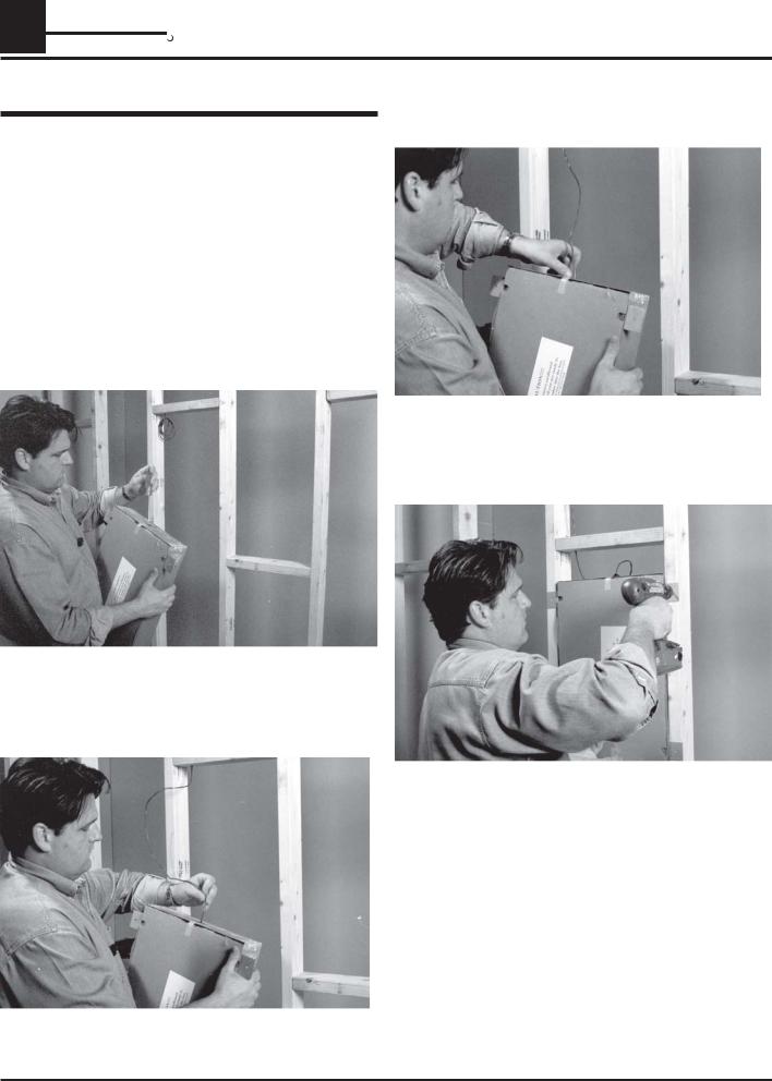
6.Once you have traced the outline, you are ready to cut out the opening and remove the piece of wallboard.
7.Retrieve the enclosure, leaving the corrugated cover on until it is time to install the loudspeaker.
8.Place the enclosure inside the cavity and trace the outline of the mounting tabs.
9.Use a utility knife to notch out the marked areas until the bare studs are exposed.
10After you finish notching out the wallboard, reach in and retrieve the audio wire.
11Using a screwdriver, bend the hood of the knockout towards the inside of the enclosure. This is where the audio wire will be routed from within the wall. Retrieve the audio wire and pass it through the knockout hole, allowing approximately 18 inches of wire to go inside the enclosure.
12.Using proper termination (saddle clamp) secure the wire to the enclosure.
Installation Instructions |
960.031 Rev # 2 |
Page 11 |
SA SOUND ADVANCE R
13Now you are ready to install the enclosure into the framing and secure it using the 1-inch drywall screws provided.
2.2 Installing the PBB4 enclosure between 16inch on-center metal stud framing after the installation of drywall.
1.Using a stud finder, determine the location of the stud framing behind the dry wall.
2.Cut out an access hole that is proximately 6 inches square.
3.Reach inside the cavity and determine the locality of the left and right stud framing, also verify that a minimum of 22-inches of unobstructed vertical space is available.
Page 12 |
960.031 Rev # 2 |
Installation Instructions |
|
|

SA SOUND ADVANCE R
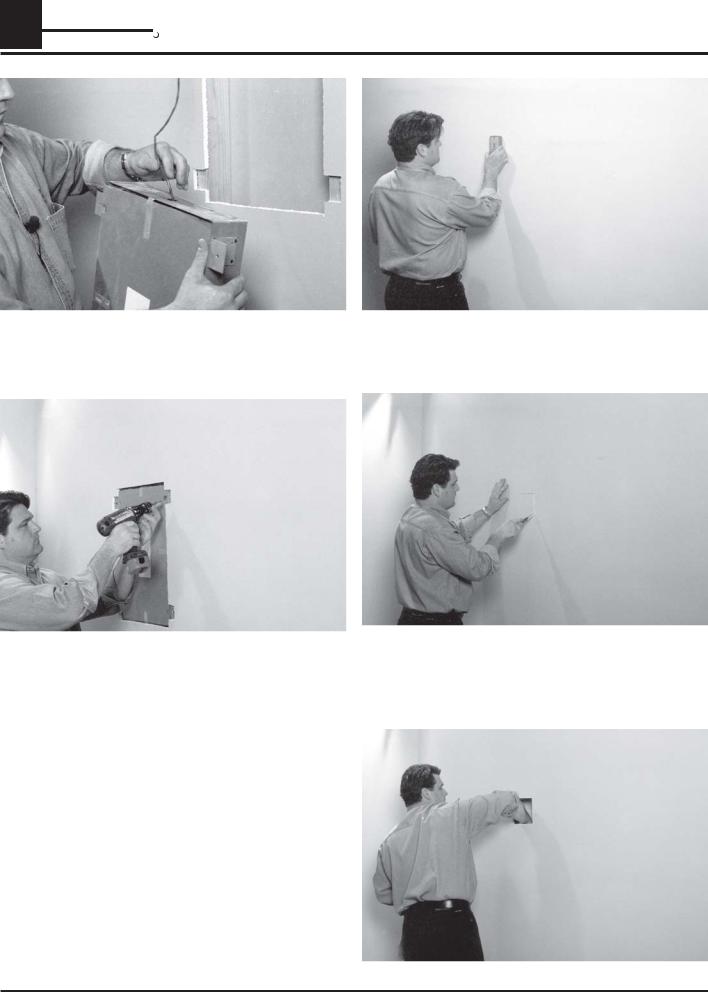
4.Starting from the access hole, make a horizontal cut until you reach the stud.
5.Retrieve the PBB with the oppening towards the surface and place the left side up to where the saw line ended at the stud and trace the outline
6.Once you have traced the outline, you are ready to cut out the opening.
7.Retrieve the enclosure, leaving the corrugated cover on until it is time to install the loudspeaker.
8.Place the enclosure inside the cavity and trace the outline of the mounting tabs.
9.Use a utility knife to notch out the marked areas until the bare studs are exposed.
10Using a screwdriver, bend the hood of the knockout towards the inside of the enclosure. This is where the audio wire will be routed from within the wall.
Installation Instructions |
960.031 Rev # 2 |
Page 13 |
 Loading...